1
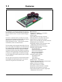
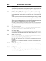
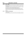
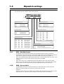
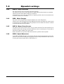
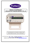
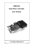
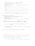
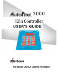
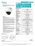
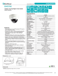
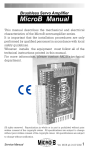
PA0076
Step Motor Driver
User Manual
JVL Industri Elektronik A/S
LB0045-03GB
Revised 9.7.2012
Copyright 1998-2012, JVL Industri Elektronik A/S. All rights reserved.
This user manual must not be reproduced in any form without prior written
permission of JVL Industri Elektronik A/S.
JVL Industri Elektronik A/S reserves the right to make changes to information
contained in this manual without prior notice.
Similarly JVL Industri Elektronik A/S assumes no liability for printing errors or
other omissions or discrepancies in this user manual.
MotoWare is a registered trademark
JVL Industri Elektronik A/S
Blokken 42
DK-3460 Birkerød
Denmark
Tlf. +45 45 82 44 40
Fax. +45 45 82 55 50
e-mail: [email protected]
Internet: http://www.jvl.dk
Contents
1
Introduction ................................................................................................................................ 4
1.1
1.2
1.3
1.4
1.5
1.6
1.7
1.8
1.9
Features ................................................................................................................................................................ 5
General board overview ....................................................................................................................................... 6
Connector overview ............................................................................................................................................. 7
Dipswitch settings .............................................................................................................................................. 10
Option setup ....................................................................................................................................................... 12
Technical Data ................................................................................................................................................... 13
Physical Dimensions .......................................................................................................................................... 14
Motor Connections ............................................................................................................................................. 15
EU declaration of conformity ............................................................................................................................ 17
JVL Industri Elektronik A/S - User Manual - Step Motor Driver PA0076
1
Introduction
JVL Industri Elektronik A/S - User Manual - Step Motor Driver PA0076
4
1.1
Features
Type PA0076 is an advanced multifunction step mo- Main Features:
tor driver that can be controlled either by step pulses • Dimmensions PA0076 = 112x160mm
PA0076-1 = 100x160mm
from an external source or by the internal step generator.
• Single supply
• Up to 4000 mini steps per revolution
The driver is characterised by an ability for control- • Controls either 2 or 4 phase step motors
ling all the basic parameters from either the internal • Noise filters at all input and outputs.
adjustments or from the external source.
• Short-circuit and thermal-overload protection
These adjustement covers - step resolution, speeds,
• Stepfrequency up to 200 kHz.
acceleration, motor currents and more.
• Adjustable standby current minimize motor
temperature and increase life time.
The Controllers can be supplied from either a AC sup• Standard DIN41612 type D connector
ply or a DC supply. The supply is not critical and can
be a simple low cost solution such as a transformer • Following input facilities:
Step and direction
connected between the mains supply and PA0076.
Slow and fast speed adjustment
An internal switch mode power supply is producing
Slow and fast start/stop
24VDC for external purposes. This supply can deliever
Motor current adjustment
a current up to 300mA which is more than enough
Energize input (enable)
for most applications which typically can be sensors • Following output facilities :
or limit switches.
Zero phase output
Fault output
All user inputs and outputs are filtered which means
Step clock output
that PA0076 will work properly also in an environ- • 24VDC output - max 300mA
ment with a high level of electrical noise.
• Internal step generator with on-board adjustment of speed and velocities.
• Motor current up to 5A peak
• Can handle motors up to 6Nm
• Automatic current reduction in standby
• Power and Fault indicators on-board.
• High efficiency Mos-Fet power stage keeps
temperature at a low level.
5
JVL Industri Elektronik A/S - User Manual - Multifunction Step Motor Driver PA0076
1.2
General board overview
DIN 2x16 pin D type connector with all external
I/O’s and power supply connections.
4 x Ø3.2mm mounting holes
when mounted on a
surface
DIP-switch (SW1)
Main setup
- Step resolution
- Motor current
- Others
Main fuse
6.3A slow blow
DIP-switch (SW2)
Option setup
- Compatibility
- Speed range reduction
Step generator adj.
(Only active if SW1.10=ON)
“Fast” Speed when activating
the “fast” input
“Slow” Speed when
activating the “slow” input
“Time”: Acc. and dec. Time
Time range:
Min.=13000 RPM/sec.
Max.=800 RPM/sec.
LED indicators
“POWER” is lit
when power is applied
“FAULT” is lit when
a short circuit of the
motor output has
happened or if a hardware
fault is present
2 x Ø2.6mm mounting holes
for frontplate
PA0076 version number
JVL Industri Elektronik A/S - User Manual - Step Motor Driver PA0076
6
1.3
Connector overview
AC or DC power supply input 1
AC1
Power Supply
AC or DC power supply input 2
AC2
44VAC max
70VDC max
Ground for power supply
GND
Ground for power supply
Status outputs
Step rate adjustment
Various
Fault output
Zero output from sequencer
Slow rate adjustement
FLT
ZERO
SADJ
Direction input
DIR
Step clock input
CLK
Energise
Signal ground
GND
Signal ground for 20 - 32A+C
Internally connected to 16 - 18A+C
ENRG
SGND
2C
2A
4C
4A
6C
6A
8C
8A
10C
10A
12C
12A
14C
14A
16C
16A
18C
18A
20C
20A
22C
22A
24C
24A
26C
26A
28C
28A
30C
30A
32C
32A
B-
Motor output, phase B-
B+
Motor output, phase B+
A-
Motor output, phase A-
A+
Motor output, phase A+
+24V
+24V Output for external use
max 300 mA
Motor Output
User supply
( 12A + 14A not used / not connected internally)
GND
Ground for power supply
GND
Ground for power supply
FAST
Start input for fast rate
SLOW
Start input for slow rate
RCOM
Common term. for rate adjust
FADJ
Fast rate adjustment
CLKO
Step clock output
Not used
CADJ
Power supply
Start inputs
Step rate adjustment
Various
Current adjustment
= Analogue signal use screened cable
TT0702GB
1.3.1
A+ / A- / B+ / B- (Motor output)
Bipolar motor output for 2 or 4 phased stepper motors. The current can be set for 2 to 5A/
phase through a dip-switch with steps of 0,5A.
The tolerance at the motor current is +/-5%.
The step resolution at the motor can also be set at the dip switch. The step resolution can
be set at 200, 400, 1000, 2000 og 4000 step per revolution if a standard motor with 200
full step per revolution is used.
1.3.2
+24V (Supply output)
This terminal is intended for external purposes and can deliever up to 300mA. The output
is protected against shortterm overloads (< 4 sec.).
1.3.3
AC1, AC2, GND (Main supply)
The main supply to the driver is connected at these terminals. If an AC-voltage is used as
supply, this must be done by using a transformator with 2 windings. The common from the
2 windings must be connected to the GND terminals (16A/C and 18A/C). The 2 windings are
connected to the AC1 and AC2 terminals. The voltage at AC1 and AC2 is thereby 180 degrees phaseshiftet. If a DC voltage is used this can be connected with minus at the GND
terminals and plus at the AC1 and AC2 terminals.
1.3.4
FLT (Fault output)
This terminal is an output which is used to indicate if the driver is functional or not.
The output is the NPN type and during normal operation it is active/closed (logic 0).
If an error occur the output is set passive whereby the terminal is three-stated.
7
JVL Industri Elektronik A/S - User Manual - Multifunction Step Motor Driver PA0076
1.3
Connector overview
1.3.5
ZERO (output)
The ZERO output indicates when the internal sequence electronic is in its zero position. The
output is a NPN type and will be active (<1V) if the zero position is achieved. During the
other steps the output is passive (floating). The output refers to the SGND terminal.
1.3.6
RCOM / SADJ / FADJ (Rate adj. common / Slow adj. / Fast adj.)
These terminals are used for adjusting the internal step generator.
The slow rate can be adjusted by a 100 kOhm potentiometer connected between the RCOM
and the SADJ terminals. The slow rate can be adjusted in the range 30-1000 full steps per
second.
The fast rate can be adjusted by a 10 kOhm potentiometer connected between the RCOM
and the FADJ terminals. The fast rate can be adjusted in the range 600 - 20.000 full steps
per second. The step generator can be started by an activating of either the FAST or SLOW
input.
The tolerance at the step frequency (the step rate) is +/-2%. This tolerance only covers the
internal functions in PA0076. If the speed is controlled by an external potiontiometer at the
SADJ or FADJ inputs the tolerance will also depend at the quality of this.
Notice that an internal scale function will make sure that the speed at the motor always is
the same regardless how the step resolution is adjusted (the number of steps per revolution).
1.3.7
DIR (Direction input)
The DIR input controls the direction of the motor rotation. The input must be controlled
from a NPN output and must not be applied a voltage higher than 15V.
1.3.8
CLK (clock input)
If the internal step generator is not used external pulses is applied at this input. A single
pulse is equal to 1 step. A single step can be 1/200 - 1/400 - 1/1000 - 1/2000 or 1/4000 of
a revolution. This resolution is determined by the actual step resolution.
1.3.9
ENRG (Energise input)
This input is used to activate the motor output. If this input is not used, dip-switch no. 6
can be set in position ON whereby the driver is always active.
If the input is pulled to 0V the motor output is activated.
If the input is not connected (left open) the motor output is released whereby the motor is
current less.
The input have to be controlled by a NPN output. The maximum allowable voltage at the
input is 15V.
1.3.10
SGND (Signal ground)
Ground terminal which is used for all the digital inputs and outputs except RCOM, SADJ og
FADJ which uses RCOM.
1.3.11
CLKO (Clock output)
This output produces a pulse every time the motor is moving a step. A step is either a full
step or a ministep. The output is producing a step wheather the internal step generator is
used or the external step input is used.
JVL Industri Elektronik A/S - User Manual - Step Motor Driver PA0076
8
1.3
Connector overview
1.3.12
FAST / SLOW
These inputs can activate the internal step generator. If the FAST input is activated the step
generator will start and accelerate to the step frequency adjusted at the internal or external
FAST potentiometer.
If the SLOW input is activated the step generator will start and accelerate to the step frequency adjusted at the internal or external SLOW potentiometer. Dip-Switch no. 10 will determine whether the internal or external potentiometer will be used.
The CLK input must not be connected when the step generator is used.
The inputs is passive when not connected. An activation of either FAST or SLOW input
means that the input terminal is connected to 0V (the SGND terminal). The inputs must
therefore be controlled from a NPN output and the maximum voltage applied must be less
than 15V.
1.3.13
CADJ (Current adjustment)
The motor current can be adjusted at this terminal but only if dip-switch 6, 7 and 8 is set
in the OFF position.
The current can be adjusted by connecting a resistor between the SGND and CADJ terminal.
9
JVL Industri Elektronik A/S - User Manual - Multifunction Step Motor Driver PA0076
1.4
Dipswitch settings
Dip-Switch layout PA0076 step motor driver
ON
1 2 3 4 5 6
7 8 9 10
Standby Current
Speed Adjustment
DIP1
ON
OFF
DIP10
ON
Internal Pot.
OFF
External Pot.
80% Standby
50% Standby
Current Scale
Motor Phase Current
DIP2
ON
OFF
DIP7
ON
OFF
ON
OFF
ON
OFF
ON
OFF
50% Reduction
100% Normal
Steps/revolution
DIP3
ON
OFF
ON
OFF
ON
OFF
ON
OFF
DIP4
ON
ON
OFF
OFF
ON
ON
OFF
OFF
DIP5
ON
ON
ON
ON
OFF
OFF
OFF
OFF
200 step/rev.
400 step/rev.
1000 step/rev.
2000 step/rev.
4000 step/rev.
4000 step/rev.
4000 step/rev.
4000 step/rev.
DIP8
ON
ON
OFF
OFF
ON
ON
OFF
OFF
DIP9
ON
ON
ON
ON
OFF
OFF
OFF
OFF
2.0A
2.5A
3.0A
3.5A
4.0A
4.5A
5.0A
External (32A)
TT0701GB
Motor Energise
DIP6
ON
OFF
Always Energised
Remote energised (ENRG input)
1.4.1
DIP1 - Standby Current
This switch controls the phase current for the motor when the motor is stationary.
The absolute value of the current is determined by DIP7, 8 and 9. Also DIP2 has an influence
since DIP2 in general is reducing the current to 50% of the value set by DIP7-9.
DIP1 set in the ON position will decrease the motor current to 50% when the motor is stationary. If DIP1 is set in the OFF position this value will be 80%.
Example :
DIP7, 8 and 9 is set in a combination which will setup the full scale current to 5.0A.
DIP2 is set to OFF which means that it has no influence. DIP1 is set to OFF which means
that the phase current for the motor will be 2.5A when the motor is stationary.
1.4.2
DIP2 - Current Scale
If small motors are used it can be convinient to reduce the motor current full scale.
DIP2 set in position ON will reduce the current scale with 50%.
Example :
If DIP7, 8, and 9 is set to 5.0 A DIP2 set in position ON it will decrease this value to 2.5A.
DIP2 also have an influence at the standby current (when motor is stationary).
JVL Industri Elektronik A/S - User Manual - Step Motor Driver PA0076
10
1.4
Dipswitch settings
1.4.3
DIP3-5 - Steps/revolution
The step resolution can be adjusted with these switches.
The resolution can be set in the range 200 to 4000 steps/revolution based at a standard
hybrid step motor with 200 full steps per revolution.
A standard rule is to set the step resolution to highest possible value since mechanical resonances is reduced to a minimum.
1.4.4
DIP6 - Motor Energise
The motor can be permanently energised if DIP6 is set in the ON position.
If DIP6 is set in the OFF position the input ENRG will determine wheather the motor should
be energised or not. The ENRG input can typically be used to release the motor if it should
be moved manually from its position.
1.4.5
DIP7-9 - Motor Phase Current.
The phase current for the motor can be set-up at these switches. The value specified is expressed as peak values during movement. When the motor is stationary the current will be
decreased to 50% or 80% of the setup value.
Notice that DIP2 set in position ON will decrease the specified values by 50%.
1.4.6
DIP10 - Speed Adjustment.
If the FAST or SLOW inputs are used it means that the internal step generator is used the
speed for either FAST or SLOW can be adjusted at the internal potentiometers (DIP10=0) or
by using the external inputs FADJ or SADJ (DIP10=1).
11
JVL Industri Elektronik A/S - User Manual - Multifunction Step Motor Driver PA0076
1.5
Option setup
SW2
SW2: Option setup
1
2
DIP1:
ON=Board setup w/software V1.1
OFF=Newest software
DIP2:
ON=Speed range reduced 4 times
OFF=Speed range normal
SW2 default settings =
Both switches in position “OFF”
1.5.1
TT0704GB
Option setup switch (SW2)
(Only available at PA0076 version 1.4 or newer)
The first switch makes it possible to be backward compatible with boards containing software version 1.1 since certain features have been changed in newer versions in order to
comply with major customer demands.
The second switch can be used to reduce the speed range for both the inputs “slow” and
“fast” by 4 times. This can be usefull for applications where a very low speed is desired.
Please notice that this feature only take effect when using the internal step generator.
JVL Industri Elektronik A/S - User Manual - Step Motor Driver PA0076
12
1.6
Technical Data
Description
Supply - Terminals AC1, AC2, GND
Min.
Supply Voltage (DC)
Max.
Units
17
70
V DC
Supply Voltage (AC)
12
44
V AC
Supply frequency if using an AC source
50
60
Hz
Power Consumption (terminals except AC1/2 left open)
Motor Output A+, A-, B+, B-
Typical
3
W
Output Voltage (dependent on supply)
0
70
V RMS
Continuous Motor Current (adjustable)
0
3.5
A RMS
Peak Motor Current
0
5
A Peak
PWM Frequency
All logic inputs
Terminals CLK, DIR, ENRG, FAST, SLOW
18
22
kHz
Logic 0
0
2.0
V
Logic 1
10
12
V
Only CLK input : Frequency (50% duty-cycle)
All logic outputs - Terminals ZERO, CLKO, FLT
0
200
kHz
Logic 0 - Specified with load < 15mA
0
1.0
V
Logic 1 - Pull up resistor must be applied externally
Diverse :
-
30
V
Operating Temperature Range
0
45
°C
Weight
Fuse size - position F1
13
20
460
6.3
grams
AT
JVL Industri Elektronik A/S - User Manual - Multifunction Step Motor Driver PA0076
1.7
Physical Dimensions
160.0
147.45
12.19
3.68
JVL Industri Elektronik A/S - User Manual - Step Motor Driver PA0076
The board edge is here
Measure in mm
Tolerances +/- 0.1 mm
52.7 (Only PA0076)
55.9 (Only PA0076)
TT0703GB
Board with:
PA0076 = 112mm
PA0076-1= 100mm
44.58
50.0 (Only PA0076-1)
0
44.58
The board edge is here
55.9 (Only PA0076)
52.7 (Only PA0076)
50.0 (Only PA0076-1)
0
14
1.8
Motor Connections
Connection of JVL and MAE
4 wire motors. Type MST17x
and HY200-xxxx-xxx-x4
Connection of JVL and MAE
motors (parallel). Type MST23x/
MST34x and HY200-xxxx-xxx-x8
Black
AB+
B-
A+
Black
A
Red
B
A
B
Red / White
AB+
B-
A
Red
B
Yellow
Black/White
Orange/White
Orange
Red
BYellow
A+
A
B
A
Driver
A+
Driver
(Blue 17xx)
Connection of Zebotronics motor
Type : SMxxx.x.xx.x (8 terminals)
Black
B+
(Red 17xx)
Yellow / White
Yellow
Connection of JVL and MAE
motors (serial). Type MST23x/
MST34x and HY200-xxxx-xxx-x8
A-
(White 17xx)
Orange
(Yellow 17xx)
Orange
Driver
Driver
A+
Black / White
Orange / White
B
Red/White
Yellow/White
AB+
B-
1
Brown
3
2
Black
White
4
Red
5
Blue
7
Yellow
6
Gray
8
Green
SM87/SM107/168.x.xx
Connection of MAE motor (unipol.)
Type HY200-1xxx-xxxxx6
A
A
B
B
SM56.x.xx
Connection of Zebotronics motor
Type : SMxxx.x.xx.x (4 terminals)
( Motor in unipolar model - 6 wires )
AB+
B-
White
Green
Black
Red
A+
A
A
B
B
White/
Green
White/
Red
Driver
Driver
A+
AB+
B-
Black
1
Green 2
Red
3
A
B
White 4
TT0005
15
JVL Industri Elektronik A/S - User Manual - Multifunction Step Motor Driver PA0076
1.8
Motor Connections
Connection of Vexta motor
Type PH2xx.xxx
Connection of Phytron motor
Type ZSx.xxx.x,x
Red
( Motor in unipolar model - 6 cables )
AB+
B-
Black
A+
Yellow
Red
A
B
A
B
White
Driver
Driver
A+
AB+
B-
Brown
Black
Yellow
Blue
A
A
B
B
Violet
White
Green
Connection of Vexta stepmotor
Type : PH2xx-xxx
Driver
A+
AB+
B-
Black
Black / White
Orange / White
Orange
Red
A
A
B
B
Red / White
Yellow / White
Yellow
TT0006
JVL Industri Elektronik A/S - User Manual - Step Motor Driver PA0076
16
1.9
EU declaration of conformity
EU - Declaration of Conformity
Manufacturer
Company Name:
Address:
Telephone:
E-mail:
Web:
JVL Industri Elektronik A/S
Blokken 42
DK-3460 Birkerød
Denmark
+45 45 82 44 40
[email protected]
www.jvl.dk
Hereby declare that:
Product
No.:
Name:
Type:
PA0076
Stepper Driver
PA0076, PA0076A or PA0076-01
- is in conformity with:
DIRECTIVE 2004/108/EC OF THE EUROPEAN PARLIAMENT AND OF THE COUNCIL of
15 december 2004 on the approximation of the laws of the Member States relating to
electromagnetic compatibility.
Was manufactured in conformity with the following national standards that
implements a harmonised standard:
EN 61800-3 Adjustable speed electrical power drives systems - Part 3:
EMC product standard including specific test methods
August 2009
Bo V. Jessen
Technical Director
JVL Industri Elektronik A/S
LX0022-01GB
17
JVL Industri Elektronik A/S - User Manual - Multifunction Step Motor Driver PA0076