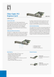
1
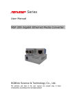
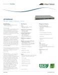
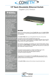
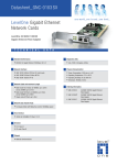
Gigabit Ethernet PCI-64
1000SX/LX Fiber Adapter
User's Manual
Release 1.2
User Manual
Table of Contents
1. Instruction ..................................................................................................................1
1-1. Overview...................................................................................................................1
1-2. Checklist ...................................................................................................................1
2. Installation...................................................................................................................1
2-1.Installing a Network Adapter Card ........................................................................1
3. Model Description......................................................................................................3
4. Network Remote Boot Configuration .......................................................................4
5. LED Description ........................................................................................................4
6. Network Parameter ...................................................................................................4
7. Technical Specifications.............................................................................................5
ii
User Manual
Revision History
Release
Date
Revision
1.00
1.1
1.2
1.2
06/09/2007
02/14/2008
06/05/2008
07/31/2008
A1
A2
A2
A3
iii
User Manual
Caution
Circuit devices are sensitive to static electricity, which can damage their delicate
electronics. Dry weather conditions or walking across a carpeted floor may cause you to
acquire a static electrical charge.
To protect your device, always:
•
Touch the metal chassis of your computer to ground the static electrical charge before
you pick up the circuit device.
•
Pick up the device by holding it on the left and right edges only.
Electronic Emission Notices
Federal Communications Commission (FCC) Statement
This equipment has been tested and found to comply with the limits for a class A
computing device pursuant to Subpart J of part 15 of FCC Rules, which are designed to
provide reasonable protection against such interference when operated in a commercial
environment.
European Community (CE) Electromagnetic Compatibility Directive
This equipment has been tested and found to comply with the protection requirements
of European Emission Standard EN55022/EN61000-3 and the Generic European Immunity
Standard EN55024.
EMC:
EN55022(2003)/CISPR-2( 2002)
IEC61000-4-2 (2001)
IEC61000-4-3( 2002)
IEC61000-4-4(2001)
class A
4K V CD, 8KV, AD
3V/m
1KV – (power line), 0.5KV – (signal line)
iv
User Manual
1. Instruction
1-1. Overview
Gigabit Ethernet PCI-64 1000SX/LX Fiber Adapter is a Gigabit Ethernet Board that
fully complies with all IEEE 802.3z and 1000Base-SX/LX standards. Two LED
indicators (LINK/ACT and FDX) on the bracket will help to oversee the board link,
activities and full-duplex status.
Gigabit Ethernet PCI-64 1000SX/LX Fiber adapters support Preboot Execution
Environment (PXE), Remote Program Load (RPL), and Bootstrap Protocol
(BOOTP). Multi-Boot Agent (MBA) is a software module that allows your networked
system to boot with the images provided by remote systems across the network.
1-2. Checklist
Before you start installing the Gigabit Ethernet PCI-64 1000SX/LX Fiber Adapter,
verify that the package contains the following items:
⎯ Gigabit Ethernet PCI-64 1000SX/LX Fiber Adapter
⎯ LAN Driver and User’s Guide CD-ROM
Please notify your sales representative immediately if any of the aforementioned
items is missing or damaged.
2. Installation
2-1.Installing a Network Adapter Card
The following instructions apply to installing the Gigabit Ethernet adapter in
most systems. Refer to the manuals that were supplied with your system for details
about performing these tasks on your particular system.
To install the network adapter card, perform the following procedure:
Warning
Before installing the adapter, ensure the system power is OFF and
unplugged from the power outlet, and that proper electrical grounding procedures
have been followed.
1. High voltage inside the system presents a safety hazard. Make sure the power is
off before removing the cover.
2. Remove the system cover and select any empty PCI-64 slot. See Figure2.
Publication date: July, 2008
Revision A3
1
User Manual
If you do not know how to identify a PCI-64 slot, refer to your system
documentation.
3. Select an empty, non-shared PCI-64 slot and remove the faceplate.
Keep the faceplate in a safe place. You may need it for future use. See
Figure3.
Note
If you cannot locate or know how to find an PCI-64 slot, refer to the
documentation that came with your system.
4.Remove the network adapter card from the shipping package and store the
packaging material in a safe location.
Publication date: July, 2008
Revision A3
2
User Manual
Caution
Wear a grounding device and observe electrostatic discharge precautions when
installing the network adapter card in a system. Failure to observe this caution
could result in damage to the card.
5. Applying even pressure at both corners of the card, push the adapter card until it
is firmly seated in the PCI-64 slot.
Make sure the card is securely seated. See Figure4.
6. Replace the system’s cover and secure it with the screws removed in Step 2.
7. Disconnect any personal antistatic devices.
8. Power the system on.
3. Model Description
PCI-64 1000SX/LX Board Models
Fiber Transceiver
Wavelength
850nm
Default
∗ SC single-mode
1310/1550nm
option
∗ LC multi-mode
850nm
option
∗ LC single-mode
1310/1550nm
option
SC multi-mode
∗: Option is available upon request
Publication date: July, 2008
Revision A3
3
User Manual
4. Network Remote Boot Configuration
4.1 Select Remote Boot Type
For entering “MBA Configuration Menu” to select Remote Boot Type (PXE,
RPL, BOOTP), please press Ctrl-S within 4 seconds after power on your
PC, otherwise, the system would go to Windows O.S.
4.2 Set Network Remote Boot
For setting network remote boot, please enter PC BIOS first, then select
“Boot” tab, after that, choose “MBA” as the priority first boot device.
4.3 Cancel Network Remote Boot
To cancel network remote boot, please change the “Boot” setting in PC
BIOS from “MBA” to “Hard Drive” or other devices.
5. LED Description
LED
Color
LINK/ACT
Green
FDX
Green
Function
Lit when cable connection is good
and speed is at 1000Mbps.
Blinks when any traffic is present.
Lit when full-duplex mode is active.
6. Network Parameter
IEEE
802.3z
Gigabit
Ethernet
1000SX
850nm
1000LX
Multi-mode Fiber Cable and Modal Bandwidth
Multi-mode
Multi-mode
62.5/125μm
50/125μm
Modal
Modal
Distance
Distance
Bandwidth
Bandwidth
160MHz-Km 220m
400MHz-Km 500m
200MHz-Km 275m
500MHz-Km 550m
Single-mode Fiber 9/125μm
Single-mode transceiver 1310nm 10Km
Single-mode transceiver 1550nm 30, 50Km
Publication date: July, 2008
Revision A3
4
User Manual
FDX
LINK/ACT
TX
RX
Fig. 1 Diagnostic LEDs and Bracket
7. Technical Specifications
Standards
: IEEE 802.3z
Gigabit Ethernet 1000Base-SX/LX
IEEE 802.3x Full-Duplex Flow Control
IEEE 802.3ad Link Aggregation
IEEE 802.1Q VLANs
IEEE 802.1p Quality of Service
Connector
: 850nm SC multi-mode (Default)
∗850nm LC multi-mode
∗1310nm SC, LC single-mode
∗1550nm SC, LC single-mode
∗: Option is available upon request
Fiber Optic Cable:
⎯
62.5/125, 50/125μm multi-mode
⎯
9/125μm single-mode
Data Transfer Mode/Speed:
⎯
Full duplex with NWay flow control
⎯
1000Mbps speed
Diagnostics LED on Bracket:
⎯
LINK/ACT
⎯
FDX
Bus Slot
Power Requirement
Ambient Temperature
Humidity
Emission
:
:
:
:
:
64/32bit PCI 2.2 Compliant
Max. 10W, +5VDC@2A
0° to 50°C
5% to 90%
Complies with EMI Standard
FCC Class A
CE Mark
Publication date: July, 2008
Revision A3
5