1
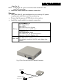
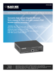
User's Manual 10/100/1000Base-T to 1000Base-X PoE PSE GbE Media Converter Release 1.0 i Table of Contents CAUTION ................................................................................................................................. 4 1. OVERVIEW .......................................................................................................................... 5 2. MODEL DESCRIPTION .......................................................................................................... 5 3. CHECKLIST ......................................................................................................................... 5 4. INSTALLING THE CONVERTER ............................................................................................... 5 5. LINK FAULT PASS THROUGH ................................................................................................. 8 6. LED DESCRIPTION ............................................................................................................ 10 7. DIP SWITCH AND RESET BUTTON ...................................................................................... 10 8. CABLE CONNECTION PARAMETER ...................................................................................... 11 9. POE PSE TP-FIBER TECHNICAL SPECIFICATIONS ............................................................... 11 ii Caution Circuit devices are sensitive to static electricity, which can damage their delicate electronics. Dry weather conditions or walking across a carpeted floor may cause you to acquire a static electrical charge. To protect your device, always: • Touch the metal chassis of your computer to ground the static electrical charge before you pick up the circuit device. • Pick up the device by holding it on the left and right edges only. European Community (CE) Electromagnetic Compatibility Directive This equipment has been tested and found to comply with the protection requirements of European Emission Standard EN55022 and EN55024. EMI EMS EN55022:2006 Class A EN61000-3-2:2006 EN61000-3-3:1995+A1:2001+A2/2005+A1/2001+A2/2005 EN55024/1998+A1:2001+A2:2003 IEC61000-4-2:2001 IEC61000-4-3:2002+A1:2002 IEC61000-4-4:1995+A1:2000+A2:2001 IEC61000-4-5:2001 IEC61000-4-6:2003 IEC61000-4-8:2001 IEC61000-4-11:2001 1 1. Overview 10/100/1000Base-T to 1000Based-SX/LX (SC/LC) IEEE802.3z/ab GbE media converter, which allows two types of network segments to be connected easily and inexpensively. Complied with IEEE802.3af Power Over Ethernet standard, this AC powered PoE media converter is a Power Sourcing Equipment (PSE) which combines data received over a TP link with –48VDC power, providing power to IEEE802.3af powered device (PD) over the existing CAT5 UTP cable. The converter includes a PD signature sensing and power monitoring features. Other features include over-current protection, under-current detection and fault protection input. The LFP (Link Fault Pass-through) allows the media converter to monitor both the fiber and copper RX ports for loss of signal. In case of a loss of RX signal on one media port, the converter will automatically disable the TX signal to the other media port, thus passing through the link fault. FEF (Far End Fault) enables the converter to stop sending link pulse to the link partner once a loss of the fiber RX signal is encountered. Then the link partner will synchronously stop sending data. FEF prevents loss of valuable data transmitted over invalid link. Combining LFP and FEF troubleshooting features, both end devices can be notified of a loss of fiber link. 2. Model Description Model MS400080 MS400082 Description 10/100/1000Base-T to 1000Base-SX PoE PSE GbE converter, MM SC 10/100/1000Base-T to 1000Base-LX PoE PSE GbE converter, SM SC 10km 3. Checklist Before you start installing the Converter, verify that the package contains the following: The PoE PSE TP-Fiber Converter AC Power Cord This User's Manual Please notify your sales representative immediately if any of the aforementioned items is missing or damaged. 4. Installing the Converter PSE TP-Fiber Converter with Powered Device (PD) ⇒ Connect the PSE media converter to an AC power source ⇒ Install the TP media cable to the IEEE 802.3af PD converter (See Fig. 2) Note: It can work as a pure converter that connects to the non-PoE converter. ⇒ Install the media cable for network connection Warning: ⇒ Verify that the AC input conforms to your country AC power requirement and then insert the power plug ⇒ Ensure that the power of PSE device is turned on ⇒ Install the media cable for network connection TP Port 10/100Base-TX Auto-Negotiation Auto-MDIX flow control for Full-Duplex backpressure for Half-Duplex 1000Base-TX Auto-Negotiation mode Auto-MDIX only for Auto-Negotiation flow control for Full-Duplex only 1000Base-SX/LX (SC/LC) with NWay flow control Fiber Port Link partner must be 1000FDX with NWay flow control Fig. 1 The View of PoE PSE Media Converter Gigabit Fiber Network Fiber Optic RJ-45 Jack PD Device (Refer to Fig. 6) Cat. 5 Cable Fig. 2 Connection among PSE PoE Converter, Fiber and TP Cables 1000Base-X Fiber Network Converter/Switch RX TX TX RX PoE PSE TP-to-GbE Fiber Converter PoE PD or PoE Splitter AC Fig. 3 PSE to PD or PoE Splitter Fig. 4 PoE PSE Media Converter Front Panel Fig. 5 PoE PSE Media Converter Rear Panel Fig. 6 Endpoint PSE RJ-45 Male Connector Note: IEEE802.3af assigns pairs on the RJ-45 connector and Cat.5 cable of Endpoint PSE. Endpoint : -48V via TP pin 1, 2, 3, 6 5. Link Fault Pass Through The Converter model of LFP (link fault pass through) in TX/FX converter application is controlled by the software and instantly takes effect. Link status on one port is propagated to the other port to notice the remote nodes. If TP port is unplugged, this converter stops transmission on fiber port. This causes the remote fiber node link to fail. LED shows the link failure on both TP and fiber ports. If fiber link fails, this converter restarts auto-negotiation on TP port but always stays in the link failure state. This causes the remote TP node link to fail. LED also shows the link failure on both TP and fiber ports. Refer to Fig. 9 shown below for the normal status when the link succeeds. Also refer to Fig. 10 and Fig. 11 for the erroneous status when TP Cable A, Fiber Cable B or Fiber Cable C fails to connect. Note: Link fault pass through (LFP) function only takes effect as S1Bit2 (see Fig. 15) is enabled. Disabled S1-Bit2 will turn this media converter into a general one. GbE Switch B D TP LFP C Fiber Cable GbE Switch Remote Station GbE Switch Remote Station A LFP TP Fig. 9 Normal status via LFP converter GbE Switch B D TP LFP C Fiber Cable A LFP TP Fig. 10 The status as TP Cable A or D is broken GbE Switch GbE Switch B D TP LFP C Fiber Cable Remote Station A LFP TP Fig. 11 The status as Fiber Cable B or C is broken GbE Fiber Switch GbE Switch B C Fiber Cable A LFP TP Remote Station Fig. 12 Normal status via LFP converter GbE Switch GbE Fiber Switch B Remote Station A C Fiber Cable LFP TP Fig. 13 The status as TP Cable A is broken GbE Switch GbE Fiber Switch B Remote Station A C Fiber Cable LFP TP Fig. 14 The status as Fiber Cable B or C is broken Note : ● ○ Indicates LNK/ACT LED Lit Indicates LNK/ACT LED Off Notice: The LFP ( Link Fault Pass Through) function can work with different link partners (for Example: Fiber port on Switch). It does not need both two converters with the same model in pairs. 6. LED Description LED Color FX LNK/ACT Green TP LNK/ACT Green TP SPD Green Amber PWR Green Green PoE PSE-TP 4W 7W 15.4W Red Green Green Green Function Lit when fiber connection is good Blinks when fiber data is present Lit when TP connection is good Blinks when TP data is present Green Lit when TP speed is 1000Mbps Amber Lit when TP speed is 100Mbps Off when TP speed is 10Mbps Lit when +5V power is coming up Lit when PoE feeding power is active Lit when PoE feeding power is disrupted (In case of overtemperature/overcurrent ) Light when PD Class Type is Class 1 Light when PD Class Type is Class 2 Light when PD Class Type is Class 0 or 3 7. DIP Switch and Reset Button Fig. 15 Reset button and S1—Bit 1, 2, 3 Configuration and Setting Reset : Once S1-1, S1-2 is changed, please press this button to have the setting taken effect. S1-1 Bridge mode : Cut through (default) or Normal S1-2 LFP : LFP enabled(default) or disabled S1-3 PoE ON/OFF : Enable(default) or disable Note: 1. S1-1 : 2. S1-3 : Cut through mode support jumbo frame size max. up to 9216Bytes. Normal mode max. frame size up to 2048 Bytes Must be set to PoE ON while power supplies to PD. 8. Cable Connection Parameter 1000Base-SX/LX network only support full-duplex mode. The Switchbased Media Converter breaks up TP and Fiber segments’ collision domain to extend the cabling distance. • TP Cable Limitations: Cat. 5 and up to 100m • Converter Fiber Cable Limitations: Multi-Mode Fiber 62.5/125μm Mode 1000SX (SC/LC) 850nm 1000LX (SC/LC) 1310nm/ 1550nm Multi-Mode Fiber 50/125μm Bandwidth Bandwidth Distance Distance MHz-Km MHz-Km 160 220m 400 500m 200 275m 500 550m Single-Mode Fiber 9/125μm Single-Mode transceiver 1310nm: 10Km Single-Mode transceiver 1550nm: 30/50Km 9. PoE PSE TP-Fiber Technical Specifications • Standards • • UTP Cable Fiber Cable : IEEE802.3u 10/100Base-TX, 100Base-FX IEEE802.3z/ab 1000Base-T IEEE802.3af Power over Ethernet : Cat. 5 cable and up to100m : 50/125, 62.5/125 or 100/140µm multi-mode 8.3/125, 8.7/125, 9/125 or 10/125µm single-mode • PSE Power Feeding Supports : “Endpoint” via TP pin 1, 2, 3, 6 • LED Indicators : POWER, PoE, TP LNK/ACT, SPD, FX LNK/ACT, 4W,7W,15.4W • Data Transfer Rate : Speed 1000Mbps 100Mbps 10Mbps • • • • • Forwarding Rate 148,8000 PPS 148,800 PPS 14,880 PPS Flow Control : IEEE802.3x compliant for full duplex Backpressure flow control for half duplex Power Requirement : AC Line: 100-240V 50-60Hz Power Consumption : 24W Ambient Temperature : 0° to 50°C Humidity : 5% to 90% • • Dimensions : 40(H) × 158(W) × 133(D) mm CE Mark Note: For connecting this device to Router, Bridge or Switch, please refer to the corresponding device's Technical Manual.