1
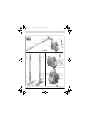
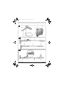
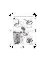
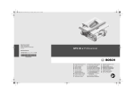
OBJ_BUCH-1513-003.book Page 1 Monday, January 16, 2012 11:29 AM
Robert Bosch GmbH
Power Tools Division
70745 Leinfelden-Echterdingen
Germany
PPR 250
www.bosch-pt.com
2 609 005 736 (2012.01) PS / 172 UNI
de
en
fr
es
pt
it
nl
Originalbetriebsanleitung
Original instructions
Notice originale
Manual original
Manual original
Istruzioni originali
Oorspronkelijke
gebruiksaanwijzing
da Original brugsanvisning
sv Bruksanvisning i original
no Original driftsinstruks
fi Alkuperäiset ohjeet
el
tr
pl
cs
sk
hu
ru
Ðñùôüôõðï ïäçãéþí ÷ñÞóçò
Orijinal işletme talimat
Instrukcja oryginalna
Původní návod k používání
Pôvodný návod na použitie
Eredeti használati utasítás
Îðèãèíàëüíîå ðóêîâîäñòâî ïî
ýêñïëóàòàöèè
uk Îðèã³íàëüíà ³íñòðóêö³ÿ ç
åêñïëóàòàö³¿
ro Instrucţiuni originale
bg Îðèãèíàëíà èíñòðóêöèÿ
sr
sl
hr
et
lv
lt
Originalno uputstvo za rad
Izvirna navodila
Originalne upute za rad
Algupärane kasutusjuhend
Instrukcijas oriģinālvalodā
Originali instrukcija
OBJ_BUCH-1513-003.book Page 2 Monday, January 16, 2012 11:29 AM
2|
Deutsch . . . . . . . . . . . . . . . . . . . . . . . . . . . . . . . . . . . . . . . . . Seite
9
English . . . . . . . . . . . . . . . . . . . . . . . . . . . . . . . . . . . . . . . . . . Page
15
Français . . . . . . . . . . . . . . . . . . . . . . . . . . . . . . . . . . . . . . . . . Page
21
Español . . . . . . . . . . . . . . . . . . . . . . . . . . . . . . . . . . . . . . . .Página
27
Português. . . . . . . . . . . . . . . . . . . . . . . . . . . . . . . . . . . . . . .Página
34
Italiano . . . . . . . . . . . . . . . . . . . . . . . . . . . . . . . . . . . . . . . . .Pagina
40
Nederlands . . . . . . . . . . . . . . . . . . . . . . . . . . . . . . . . . . . . .Pagina
46
Dansk . . . . . . . . . . . . . . . . . . . . . . . . . . . . . . . . . . . . . . . . . . . Side
52
Svenska . . . . . . . . . . . . . . . . . . . . . . . . . . . . . . . . . . . . . . . . . Sida
57
Norsk . . . . . . . . . . . . . . . . . . . . . . . . . . . . . . . . . . . . . . . . . . . Side
63
Suomi. . . . . . . . . . . . . . . . . . . . . . . . . . . . . . . . . . . . . . . . . . . .Sivu
68
ÅëëçíéêÜ. . . . . . . . . . . . . . . . . . . . . . . . . . . . . . . . . . . . . . . . Óåëßäá
74
Türkçe . . . . . . . . . . . . . . . . . . . . . . . . . . . . . . . . . . . . . . . . . Sayfa
80
Polski . . . . . . . . . . . . . . . . . . . . . . . . . . . . . . . . . . . . . . . . . .Strona
86
Česky . . . . . . . . . . . . . . . . . . . . . . . . . . . . . . . . . . . . . . . . . . Strana
92
Slovensky. . . . . . . . . . . . . . . . . . . . . . . . . . . . . . . . . . . . . . . Strana
98
Magyar . . . . . . . . . . . . . . . . . . . . . . . . . . . . . . . . . . . . . . . . . . Oldal 104
Ðóññêèé . . . . . . . . . . . . . . . . . . . . . . . . . . . . . . . . . . . . . Ñòðàíèöà 110
Óêðà¿íñüêà. . . . . . . . . . . . . . . . . . . . . . . . . . . . . . . . . . . .Ñòîð³íêà 117
Română . . . . . . . . . . . . . . . . . . . . . . . . . . . . . . . . . . . . . . . .Pagina 123
Áúëãàðñêè . . . . . . . . . . . . . . . . . . . . . . . . . . . . . . . . . . . Ñòðàíèöà 129
Srpski. . . . . . . . . . . . . . . . . . . . . . . . . . . . . . . . . . . . . . . . . . Strana 136
Slovensko . . . . . . . . . . . . . . . . . . . . . . . . . . . . . . . . . . . . . . . Stran 142
Hrvatski . . . . . . . . . . . . . . . . . . . . . . . . . . . . . . . . . . . . . . Stranica 147
Eesti . . . . . . . . . . . . . . . . . . . . . . . . . . . . . . . . . . . . . . . . . Lehekülg 153
Latviešu . . . . . . . . . . . . . . . . . . . . . . . . . . . . . . . . . . . . . . Lappuse 159
Lietuviškai . . . . . . . . . . . . . . . . . . . . . . . . . . . . . . . . . . . . Puslapis 165
2 609 005 736 | (16.1.12)
Bosch Power Tools
OBJ_BUCH-1513-003.book Page 3 Monday, January 16, 2012 11:29 AM
|3
3
2
4
5
1
PPR 250
8
9
19
7
20
18
21
22
23
24
10
26
11
25
6
12
14
15
16
Bosch Power Tools
27
28
29
13
15
2 609 005 736 | (16.1.12)
OBJ_BUCH-1513-003.book Page 4 Monday, January 16, 2012 11:29 AM
4|
A
21
12
3
B1
2
2
3
10
12
B2
1
2
12
8
8
3
2 609 005 736 | (16.1.12)
1
6
Bosch Power Tools
OBJ_BUCH-1513-003.book Page 5 Monday, January 16, 2012 11:29 AM
|5
C1
29
C2
D
27
18
28
23
E1
E2
37
3
16
15
15
17
17
16
Bosch Power Tools
15
2 609 005 736 | (16.1.12)
OBJ_BUCH-1513-003.book Page 6 Monday, January 16, 2012 11:29 AM
6|
F
14
G1
M22
M24
31
31
30
30
G2
27
20
+
32
21
23
22
2 609 005 736 | (16.1.12)
Bosch Power Tools
OBJ_BUCH-1513-003.book Page 7 Monday, January 16, 2012 11:29 AM
|7
G3
3
31
27
32
34
G4
20
33
H
35
Bosch Power Tools
2 609 005 736 | (16.1.12)
OBJ_BUCH-1513-003.book Page 8 Monday, January 16, 2012 11:29 AM
8|
I1
I2
36
36
37
I3
2 609 005 736 | (16.1.12)
38
Bosch Power Tools
OBJ_BUCH-1513-003.book Page 16 Monday, January 16, 2012 11:29 AM
16 | English
Symbol
Meaning
Adapting the height-adjustable paintbucket coupling to the height of the paint
bucket:
base unit must always stand level on the
flor.
leftward
Pump lock engaged (pump
function possible only in this
position)
rightward
Pump lock disengaged
Product Description and
Specifications
Intended Use
The machine is intended only for painting water-based dispersion wall paint.
Use the machine only when you can fully assess all functions
and handle them without limitation, or after having received
appropriate instructions.
Product Features
The numbering of the components shown refers to the representation of the power tool on the graphic pages.
1 Paint applicator extension
2 Feed hose
3 Paint applicator
4 Intake hose
5 Base unit
Paint applicator
6 Remote control holder
7 Trigger switch
8 Remote control (PaintControl system)
9 Extension handle
10 Screw connection of extension
11 Paint applicator handle
12 Guide groove for feed hose
13 Feed-hose connection on paint applicator
14 Bucket holder
15 Roll holder
16 Paint roll
17 Roll axle
Base unit
18 On/Off switch
19 Carrying handle
20 Pump lid
21 Holding clamp
22 Paint filter
2 609 005 736 | (16.1.12)
23
24
25
26
27
28
29
Pump lock
Pedestal
Pump-hose connection
Feed-hose connection on base unit
Double-SDS-connector
Pump-hose holding clip
Height-adjustable paint-bucket coupling
Components for cleaning
30 Mixing-nozzle spanner
31 Water tap-adapter with gasket
32 SDS connection on paint filter
33 Pump hose
34 Bypass hose
35 Rotor
36 Paint distributor
37 Paint chamber
38 Distributor plate
*Accessories shown or described are not part of the standard delivery scope of the product. A complete overview of accessories
can be found in our accessories program.
Technical Data
Electric Paint Roller
Article number
Rated power input
Paint delivery capacity
Required time for application of
paint on 2 m2
Length
– Paint applicator
– Paint applicator + extension
– Feed hose
Dimensions of paint roll
– Width
– Shank diameter
– Core diameter (incl. pile)
– Pile height
– Pile material
Weight according to
EPTA-Procedure 01/2003
Protection class
– Base unit
– Trigger switch with remote
control
PPR 250
3 603 BA0 0..
W
35
ml/min
400
min
1
cm
cm
m
40
120
5
cm
mm
mm
mm
25
8
45–50
11
Polyester
kg
3.7
* Protection against water splash from all directions
IP X4 *
IP X5 **
** Protection against water jets from all directions
The values given are valid for a nominal voltage [U] of 230 V. For different voltages and models for specific countries, these values can vary.
Please observe the article number on the type plate of your machine.
The trade names of the individual machines may vary.
Noise Information
Typically the A-weighted sound pressure level of the product
is less than 70 dB(A).
Bosch Power Tools
OBJ_BUCH-1513-003.book Page 17 Monday, January 16, 2012 11:29 AM
English | 17
Declaration of Conformity
We declare under our sole responsibility that the product described under “Technical Data” is in conformity with the following standards or standardization documents: EN 60335,
EN 300 220-1:2006, EN 300 220-2:2007, EN 301 4891:2008, EN 301 489-3:2002 according to the provisions of
the directives 2011/65/EU, 2006/95/EC, 2004/108/EC,
1999/5/EC.
11
Dr. Egbert Schneider
Dr. Eckerhard Strötgen
Senior Vice President
Engineering Director
Engineering
PT/ESI
– Cover or mask off floors, furnishings, door and window
frames, etc.
– Also, sufficiently underlay the paint bucket and base unit
with covering-off material (foil, cardboard, etc.).
Preparing the Paint
– Prepare the paint according to the manufacturer’s instructions.
– Stir paint thoroughly and dilute as required.
When the painting result is not satisfactory or no paint comes
out: See “Correction of Malfunctions”, page 18.
f Before any work on the machine itself, pull the mains
plug.
Coupling the Base Unit and the Paint Bucket
(see figures C1–C2)
– Set down base unit 5 level on the floor next to the opened
paint bucket.
– Pull the height-adjustable paint-bucket coupling 29 upward to the stop.
– Hold the paint bucket handle upright and slide the hooks of
the paint-bucket coupling down to the edge of the paint
bucket.
The paint bucket handle must always be positioned between the hooks of the paint-bucket coupling.
– Insert the paint filter 22 to the bottom of the paint bucket.
– Fasten the intake hose 4 in the holding clip 28.
Unreel the Feed Hose (see figure A)
Starting Operation
Robert Bosch GmbH, Power Tools Division
D-70745 Leinfelden-Echterdingen
Leinfelden, 26.09.2011
Assembly
– Open holding clamp 21 and completely unreel feed hose 2
from base unit 5.
– Lock holding clamp 21 again.
Note: When painting only with the paint applicator 3 (without
extension 1), the feed hose 2 can be fastened in one of the
two exterior guide grooves 12 for more convenient working.
Mounting the Extension (see figures B1 – B2)
– Screw the screw connection 10 of the extension into the
paint applicator 3.
– Fasten feed hose 2 in the straight guide grooves 12 of
paint applicator 3 and extension 1.
– Remove remote control 8 from paint applicator 3 and clip
it into holder 6 of extension 1.
Operation
f Before any work on the machine itself, pull the mains
plug.
Preparing for Operation
f Working close to the edge of open waters or on neighbouring areas in the direct vicinity of open waters is not
permitted.
When purchasing paint, observe its environmental compatibility.
Preparing the Surface to be Painted
The surface to be painted must be clean, dry and free of
grease.
When working indoors, all non-covered surface can be soiled.
Therefore, thoroughly prepare the area around the surface to
be painted:
Bosch Power Tools
f Observe correct mains voltage! The voltage of the power source must agree with the voltage specified on the
nameplate of the machine. Power tools marked with
230 V can also be operated with 220 V.
f Always place the base unit and the paint bucket on a
level surface. When operating the paint roller on a ladder
or an inclined surface, the base unit and the paint bucket
can tip over or fall down. This can lead to injury and contamination from the coating material.
f Do not cover off the base unit. Otherwise, a possible malfunction cannot be detected.
f Keep other electrical machines/devices away while using the paint roller or cover them off adequately. Possibly occurring paint splashes can lead to accidents and soiling.
f Regularly provide for proper ventilation in the working
range and for sufficient fresh air throughout the complete area.
f Wear safety glasses/goggles. This will protect your eyes
against splashing or ejected paint.
Wear appropriate work clothes. Paint is difficult to remove
from clothing.
Prevent the hose system from being constricted, e. g.,
through crushing, kinking or pulling! Do not stand on the feed
hose 2.
Keep the hose system away from heat sources.
Do not pull the hoses. Especially when moving the base unit,
do not pull it by the feed hose 2. Carry the base unit only by
the carrying handle 19.
2 609 005 736 | (16.1.12)
OBJ_BUCH-1513-003.book Page 18 Monday, January 16, 2012 11:29 AM
18 | English
Switching On (see figure D)
– Plug the mains plug into a socket outlet.
– Make sure that the pump lock 23 is engaged.
– To start the machine, push the On/Off switch 18 to the “I”
position.
– Grasp the paint applicator 3 or extension 1 by the respective handle and direct the paint roll 16 toward the surface
to be painted.
– Press the trigger switch 7 on the remote control 8.
Switching Off
– Release the trigger switch 7.
– To switch off the machine, push the On/Off switch 18 to
the “0” position.
– Pull the mains plug from the socket outlet.
– Disengage pump lock 23.
To relieve the lock tension, lightly push the pump lid 20 upward, if required.
Working Advice
Painting
Before painting, moisten new or dried paint rolls with water.
When the paint roll is new or dry, it takes approx. six lanes until the paint application is homogeneous and without streaks.
Filling an empty feed hose takes approx. one minute.
– Press the trigger switch 7 to apply a sufficient amount of
paint on the paint roll 16 and uniformly move the paint roll
up and down.
– Avoid interruptions within the surface to be painted.
Evenly guiding the paint roll will lead to a uniform surface
quality.
Regulating the Paint Amount during Painting
The paint amount can be regulated with the trigger switch.
– Press the trigger switch 7 until the application of paint on
the paint roll is homogeneous.
– Afterwards, release the trigger switch until the application
of paint on the painting surface is no longer opaque.
– Then, refill the paint chamber again with a sufficient
amount of paint (press trigger switch 7 approx. 5 seconds).
Changing the Paint Roll (see figures E1 – E2)
Remove the paint roll from the paint applicator for cleaning or
when the paint roll is worn.
– Pull the roll holders 15 apart and allow the paint roll 16 to
slide out of the paint applicator 3.
To prevent the paint-soaked paint roll from drying out until it
has been washed out, it is best to immerse it into a water
bucket.
Appropriate new paint rolls can be found in our Bosch accessories program.
Paint rolls from other manufacturers can also be used, when
the respective dimensions are observed (see “Technical Data”, page 16).
Insert a new paint roll as follows:
– Pull the roll axle 17 out of the old paint roll 16 and slide the
new paint roll on the roll axle until centred.
– Insert the roll axle 17 on one side in the roll holder 15 until
it fits.
– Press the paint roll into the roll holder of the other side.
The paint roll must be able to rotate freely.
Placing Down the Paint Applicator (see figure F)
– Place down the paint applicator 3 on the edge of the paint
bucket so that it rests on the bucket holder 14.
Correction of Malfunctions
Problem
Paint application unsatisfactory.
No paint coming out of paint
applicator 3.
The remote control 8 is
inoperative.
2 609 005 736 | (16.1.12)
Cause
The hoses are obstructed. No or too little
paint being transported.
The paint is too viscous and therefore cannot
be transported.
The pump lock 23 is not engaged.
Corrective Measure
Make sure that non of the hoses are squeezed or
creased.
Stir paint thoroughly and dilute as required.
Make sure that pump lid 20 is properly inserted
and locked.
The paint bucket is empty.
Refill the paint bucket with fresh paint or exchange the empty paint bucket against a full one.
The paint is too viscous and cannot be drawn Stir paint thoroughly and dilute as required.
in by the pump.
The hoses are obstructed.
Clean the hose system (see “Cleaning”, page 19).
The hoses are obstructed. No or too little
Make sure that non of the hoses are squeezed or
paint being transported.
creased.
The base unit is switched off.
Switch the base unit on (see “"Switching
On"Switching On”, page 18).
The remote control battery is empty.
Contact an authorised service agent for Bosch
power tools.
Have the component replaced there.
Bosch Power Tools
OBJ_BUCH-1513-003.book Page 19 Monday, January 16, 2012 11:29 AM
English | 19
Maintenance and Service
f Before any work on the machine itself, pull the mains
plug.
Cleaning
After painting, the system must be pumped empty and all
paint-carrying parts must be cleaned.
There are two possibilities for cleaning the system:
– EasyClean: Using universal connectors, the system is connected to a water tap and flushed.
– Alternative possibility: The system pumps fresh water
from a bucket for cleaning.
Proper cleaning is a prerequisite for perfect operation of the
electric paint roller. No warranty claims can be undertaken if
cleaning is not carried out or is carried out incorrectly.
Keep the base unit, the holding clip 28 and the remote control
8 clean. Clean them with a moist cloth. The base unit and the
remote control may not be immersed into water.
Always clean the paint roll, the paint applicator and the hose
system with water.
Preparation
– Place down the paint applicator 3 on the edge of the paint
bucket so that it rests on the bucket holder 14.
– Loosen the double-SDS-connector 27 from the holding
clip 28 and completely remove the intake hose 4 and the
paint filter 22 from the paint bucket.
– Remove the paint roll 16 from the paint applicator 3 (see
“Changing the Paint Roll”, page 18).
– Hold the paint applicator 3 above the paint bucket and
press the trigger switch 7 until the hose system is pumped
empty and no more paint comes out of the paint applicator.
– Release the trigger switch 7 and switch the power tool off.
– Pull the mains plug from the socket outlet.
EasyClean (see figures G1–G4)
Note: Use only the supplied hoses and adapters for connecting to the water supply.
Preparing the water tap:
– Unscrew the mixing nozzle from a water tap using the supplied mixing-nozzle spanner 30 or a suitable tool.
– Screw the fitting adapter 31 (M22 or M24 thread) in or on
the water tap.
Additional water-tap adapters are available in the Bosch
accessories program.
Separating paint-carrying components:
– Unlatch holding clamp 21.
– Disengage pump lock 23.
To relieve the lock tension, lightly push the pump lid 20 upward, if required.
– Push the pump lid 20 downward to the stop and then carefully lift it out of the housing opening of base unit 5.
– Loosen the SDS connection 32 at the bottom part of the intake hose 4.
Bosch Power Tools
Flushing the system:
– Carry the paint applicator 3, feed hose 2, pump lid 20 and
intake hose 4 to the prepared water tap.
Please note that paint may escape or leak from the system.
– Attach the double-SDS-connector 27 to adapter 31 on the
water tap.
– Hold the paint applicator 3 over a suitable collecting container (e. g. a bucket).
– Carefully open the water tap and run lukewarm water
through the system.
– When flushing, lightly press pump hose 33 together several times.
This will lead to better cleaning results.
Additionally, this also cleans bypass hose 34, which prevents the rotor from overloading in case of excessive pressure in the hose system.
– Flush the system until only clear water comes out of the
paint applicator.
– Clean the paint filter 22 and the intake hose 4 (connect
SDS connection 32 to the water tap and flush; additional
cleaning of paint filter with brush).
– Release the adapter 31 from the water tap and from the
double-SDS-connector 27.
Screw the mixing nozzle back onto water tap.
Cleaning the paint applicator and the paint roll:
– See “Cleaning the Paint Applicator and the Paint Roll”,
page 20.
Mounting together the dried components:
– Allow all components to dry thoroughly.
If possible, hang up the paint roll 16 to dry.
If the paint roll is placed down to dry, the pile will be deformed. This may lead to an uneven surface quality when
using the paint roller the next time.
– Reconnect the intake hose 4 to the SDS connection 32 on
the paint filter 22.
– Manually turn rotor 35 to the indicated position (see figure
G4) in order to avoid damage to pump hose 33 when inserting pump lid 20.
– Reinsert the pump lid 20 into the housing opening and
push it upward to the stop.
– Shut pump lock 23 until it engages.
– Lock holding clamp 21 again.
Alternative Cleaning Method (see figure H)
Note: This cleaning method takes somewhat longer than the
EasyClean method.
– Couple base unit 5 to the water bucket (also see “Coupling
the Base Unit and the Paint Bucket”, page 17).
– Insert paint filter 22 to the bottom of the water bucket.
– Fasten the intake hose 4 in the holding clip 28.
– Plug the mains plug into a socket outlet.
– Make sure that the pump lock 23 is engaged.
– To start the machine, push the On/Off switch 18 to the “I”
position.
– Hold paint applicator 3 over a suitable collecting container
(e.g. a bucket) and actuate trigger switch 7 until only clear
water comes out of the paint applicator and no more paint
can be seen in the hoses (visual check).
2 609 005 736 | (16.1.12)
OBJ_BUCH-1513-003.book Page 20 Monday, January 16, 2012 11:29 AM
20 | English
Always lightly move the hoses.
This will lead to better cleaning results.
– Clean the paint applicator and the paint roll: See “Cleaning
the Paint Applicator and the Paint Roll”, page 20.
– Allow all components to dry thoroughly.
If possible, hang up the paint roll 16 to dry.
If the paint roll is placed down to dry, the pile will be deformed. This may lead to an uneven surface quality when
using the paint roller the next time.
Cleaning the Paint Applicator and the Paint Roll
(see figures I1–I3)
After flushing the system, some of the components still have
to be cleaned manually.
– Remove paint remainders from paint applicator 3 using a
brush.
– Pull paint distributor 36 out of the paint chamber 37.
For easier cleaning, turn the paint distributor by 90°.
– Remove the distributor plate 38 from the paint distributor
36.
For this, lift the distributor plate on one side and pull it laterally out of the retaining clamps.
– Remove paint remainders from of the distributor plate 38,
the paint distributor 36 and from of the paint chamber 37
using a small brush.
– Wash out the paint roll 16 thoroughly.
Storage
Before storing, the electric paint roller must be properly
cleaned and all components dried.
– Slide distributor plate 38 laterally into the retaining clamps
in paint distributor 36.
– Clip paint distributor 36 into the paint chamber 37.
– Wind up feed hose 2 around the base unit 5 and affix it with
holding clamp 21.
– Slide down paint-bucket coupling 29 completely to the
bottom.
– Insert paint roll 16 into paint applicator 3 (see “Changing
the Paint Roll”, page 18).
Material Disposal
Paint and dried paint remainders must be disposed of in an
environmentally-friendly manner. Observe the manufacturer’s instructions for disposal and the local regulations for hazardous waste disposal.
Chemicals harmful to the environment may not be disposed
of into soil, groundwater or bodies of water. Never pour
chemicals harmful to the environment into the sewerage system!
Maintenance
If the replacement of the supply cord is necessary, this has to
be done by Bosch or an authorized Bosch service agent in order to avoid a safety hazard.
If the machine should fail despite the care taken in manufacturing and testing procedures, repair should be carried out by
an after-sales service centre for Bosch power tools.
In all correspondence and spare parts order, please always include the 10-digit article number given on the type plate of
the machine.
2 609 005 736 | (16.1.12)
After-sales Service and Customer Assistance
Our after-sales service responds to your questions concerning maintenance and repair of your product as well as spare
parts. Exploded views and information on spare parts can also be found under: www.bosch-pt.com
Our customer service representatives can answer your questions concerning possible applications and adjustment of
products and accessories.
Great Britain
Robert Bosch Ltd. (B.S.C.)
P.O. Box 98
Broadwater Park
North Orbital Road
Denham
Uxbridge
UB 9 5HJ
Tel. Service: +44 (0844) 736 0109
Fax: +44 (0844) 736 0146
E-Mail: [email protected]
Ireland
Origo Ltd.
Unit 23 Magna Drive
Magna Business Park
City West
Dublin 24
Tel. Service: +353 (01) 4 66 67 00
Fax: +353 (01) 4 66 68 88
Australia, New Zealand and Pacific Islands
Robert Bosch Australia Pty. Ltd.
Power Tools
Locked Bag 66
Clayton South VIC 3169
Customer Contact Center
Inside Australia:
Phone: +61 (01300) 307 044
Fax: +61 (01300) 307 045
Inside New Zealand:
Phone: +64 (0800) 543 353
Fax: +64 (0800) 428 570
Outside AU and NZ:
Phone: +61 (03) 9541 5555
www.bosch.com.au
Republic of South Africa
Customer service
Hotline: +27 (011) 6 51 96 00
Gauteng – BSC Service Centre
35 Roper Street, New Centre
Johannesburg
Tel.: +27 (011) 4 93 93 75
Fax: +27 (011) 4 93 01 26
E-Mail: [email protected]
Bosch Power Tools