1
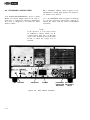
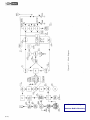
Downloaded by
Amateur Radio Directory
TABLE OF CONTENTS
CHAPTER I
INTRODUCTION
Page
l-l
. . . . . . . . . . . . . . . . . . . . . . .
l-l.
GENERAL DESCRIPTION
.
.
.
.
.
.
.
.
.
.
.
.
.
.
.
.
.
.
.
.
.
l-l
l-2.
MANUAL COVERAGE
.
.
.
.
.
.
.
.
.
.
.
.
.
.
.
.
.
.
.
.
.
l-l
.
.
.
.
.
.
.
.
.
.
.
.
.
.
.
.
.
.
l-3
INSTALLATION.
. . . . . . . . . . . . . . . . . . . . . . .
2-l
2-1.
UNPACKING .
.
.
.
.
.
.
.
.
.
.
.
.
.
.
.
.
.
.
.
.
.
.
.
.
.
2-l
2-2.
LOCATION
.
.
.
.
.
.
.
.
.
.
.
.
.
.
.
.
.
.
.
.
.
.
.
.
.
2-l
2-3.
MOBILE INSTALLATION
.
.
.
.
.
.
.
.
.
.
.
.
.
.
.
.
.
.
.
.
.
2-l
2-4.
POWER REQUIREMENTS
.
.
.
.
.
.
.
.
.
.
.
.
.
.
.
.
.
.
.
.
.
2-l
2-5.
MOUNTING
.
.
.
.
.
.
.
.
.
.
.
.
.
.
.
.
.
.
.
.
.
.
.
.
.
.
2-l
2-6.
ANTENNA.
.
.
.
.
.
.
.
.
.
.
.
.
.
.
.
.
.
.
.
.
.
.
.
.
.
.
2-l
2-7.
SPEAKER .
.
.
.
.
.
.
.
.
.
.
.
.
.
.
.
.
.
.
.
.
.
.
.
.
.
.
2-l
2-8.
MICROPHONE
.
.
.
.
.
.
.
.
.
.
.
.
.
.
.
.
.
.
.
.
.
.
.
.
.
2-l
2-9.
STATIONARY INSTALLATION
.
.
.
.
.
.
.
.
.
.
.
.
.
.
.
.
.
.
.
2-2
2-10.
POWER REQUIREMENTS
2-11.
VIEWING ANGLE
.
.
2-12.
ACCESSORIES
.
.
.
SPECIFICATIONS
CHAPTER II
.
.
.
.
.
.
.
.
.
.
.
.
.
.
.
.
.
.
.
.
.
.
.
.
.
.
.
.
.
2-2
.
.
.
.
.
.
.
.
.
.
.
.
.
.
.
.
.
.
.
.
.
.
2-2
.
.
.
.
.
.
.
.
.
.
.
.
.
.
.
.
.
.
.
.
.
.
2-2
OPERATION
. . . . . . . . . . . . . . . . . . . . . . . . .
3-l
3-l.
GENERAL.
.
.
.
.
.
.
.
.
.
.
.
.
.
.
.
.
.
.
.
.
.
.
.
.
.
3-l
3-2.
MODE SWITCH .
.
.
.
.
.
.
.
.
.
.
.
.
.
.
.
.
.
.
.
.
.
.
.
.
3-l
3-3.
BLANKER SWITCH
.
.
.
.
.
.
.
.
.
.
.
.
.
.
.
.
.
.
.
.
.
.
.
3-l
3-4.
VFODIAL.
. . . . . . . . . . . . . . . . . . . . . . . . . . .
3-l
3-5.
TUNING PROCEDURE
3-6.
BIAS ADJUSTMENT
CHAPTER III
.
.
.
.
.
.
.
.
.
.
.
.
.
.
.
.
.
.
.
.
.
.
.
.
3-l
.
.
.
.
.
.
.
.
.
.
.
.
.
.
.
.
.
.
.
.
.
.
3-l
.
.
.
.
.
.
.
.
.
.
.
.
.
.
.
FRONT PANEL CONTROLS
.
.
.
.
.
.
3-3
OTHER CONTROLS
.
.
.
.
.
.
.
.
.
.
.
.
.
.
.
.
.
.
.
.
.
.
.
3-4
3-7.
TUNE UP .
.
.
.
.
.
.
.
.
.
.
.
.
.
.
.
.
.
.
.
.
.
.
.
.
.
3-5
3-8.
SSB OPERATION
.
.
.
.
.
.
.
.
.
.
.
.
.
.
.
.
.
.
.
.
.
.
.
.
3-5
.
i
TABLE OF CONTENTS (continued)
3-9.
CW OPERATION.
.
.
Page
3-6
3-10.
AM OPERATION
. . . . . . . . . . . . . . . . . . . . . . . . .
3-6
3-11.
OPERATION NEAR BAND EDGES
.
.
.
.
.
.
.
.
.
.
.
.
.
.
.
.
3-12.
OPERATION WITH A LINEAR AMPLIFIER
.
.
.
.
.
.
.
.
.
.
.
.
.
.
.
3-6
3-13.
NOVICE OPERATION.
.
.
.
.
.
.
.
.
.
.
.
.
.
.
.
3-7
THEORY OF OPERATION.
. . . . . . . . . . . . . . . . . . .
4-l
4-l.
GENERAL.
.
.
.
.
.
.
.
.
.
.
.
.
.
.
.
.
.
.
.
.
.
.
4-l
4-2.
RECEIVER CIRCUITRY .
.
.
.
.
.
.
.
.
.
.
.
.
.
.
.
.
.
.
.
.
.
4-l
4-3.
TRANSMITTER CIRCUITRY
.
.
.
.
.
.
.
.
.
.
.
.
.
.
.
.
.
.
.
.
4-2
CHAPTER IV
CHAPTER V
ii
.
.
.
.
.
.
.
.
.
.
.
.
.
.
.
.
.
.
.
.
.
.
.
.
.
.
.
.
.
.
.
.
.
.
.
-
3-6
MAINTENANCE. . . .
5-1
5-l.
SERVICE DATA. . . . .
5-l
5-2.
TOP COVER REMOVAL . .
5-l
5-3.
BOTTOM COVER REMOVAL
5-l
5-4.
TUBE REPLACEMENT . .
5-l
5-5.
TROUBLE SHOOTING . .
5-l
5-6.
TEST EQUIPMENT. . . .
5-2
5-7.
ALIGNMENT PROCEDURES
5-2
5-8.
CRYSTAL CALIBRATOR .
5-2
5-9.
9.0 MHz OSCILLATOR . .
5-2
5-10.
INJECTION CRYSTAL OSCILLATOR
5-11.
VFO ADJUSTMENT
5-12.
INJECTION
5-13.
RECEIVER IF
5-14.
BALANCED MODULATOR AND CARRIER BALANCE
.
.
.
.
.
.
.
.
.
.
.
5-5
5-15.
FILTER MATCHING TRANSFORMER .
.
.
.
.
.
.
.
.
.
.
.
.
.
.
.
.
5-6
5-16.
MIXER AND IF ALIGNMENT .
5-17.
PA NEUTRALIZATION
5-18.
TRANSMITTER
5-19.
S METER ADJUSTMENT.
.
COUPLER
.
.
.
.
.
.
.
.
.
.
.
.
.
.
.
.
.
.
.
.
5-2
.
.
.
.
.
.
.
.
.
.
.
.
.
.
.
.
.
.
.
.
.
.
5-2
.
.
.
.
.
.
.
.
.
.
.
.
.
.
.
.
.
.
.
.
.
.
5-2
.
.
.
.
.
.
.
.
.
.
.
.
.
.
.
.
.
.
.
.
.
.
5-5
.
.
.
.
.
.
.
.
.
.
.
.
.
.
.
.
.
.
.
5-6
.
.
.
.
.
.
.
.
.
.
.
.
.
.
.
.
.
.
.
5-6
NEUTRALIZATION.
.
.
.
.
.
.
.
.
.
.
.
.
.
.
.
.
.
5-6
.
.
.
.
.
.
.
.
.
.
.
.
.
.
.
.
.
5-6
.
.
.
.
.
.
.
LIST OF ILLUSTRATlONS
Figure
l-l.
TR-4C SIDEBAND TRANSCEIVER .....................
Page
l-2
2-l.
MICROPHONE
......................
2-l
2-2.
REAR CHASSIS CONNECTORS
.................... .- .
2-2
2-3.
ELECTRICAL CONNECTIONS REQUIRED FOR MOBILE INSTALLATION
2-4.
MOBILE INSTALLATION MOUNTING OPTIONS
2-5.
VIEWING ANGLE OPTIONS IN A STATIONARY INSTALLATION
..........
2-5
2-6.
CONNECTING THE AC-4 POWER SUPPLY AND MS-4 SPEAKER
..........
2-5
2-7.
CONNECTING THE AC-4 POWER SUPPLY, RV-4C REMOTE VFO AND
CONNECTIONS
A LINEAR AMPLIFIER
.......
................
.........................
2-3
2-4
2-6
2-8.
CONNECTING THE AC-4 POWER SUPPLY AND THE L-4B LINEAR AMPLIFIER
2-9.
CONNECTING AN EXTERNAL RECEIVER
3-l.
FRONT PANEL CONTROLS
4-l.
BLOCK DIAGRAM ...........................
4-4
5-1.
ALIGNMENT LOCATIONS, TOP VIEW ....................
5-8
5-2.
ALIGNMENT LOCATIONS, BOTTOM VIEW ..................
5-9
5-3.
AC-4 POWER SUPPLY SCHEMATIC.
....................
5-11
5-4.
DC-4 POWER SUPPLY SCHEMATIC.
....................
5-11
5-5.
TR-4C SCHEMATIC
....
2-6
..................
2-7
.......................
3-2
..........................
5-l 1
...
III
CHAPTER I
INTRODUCTION
l-l. GENERAL DESCRIPTION.
an MC-4 Mobile Console, and a TR-4C VHF
Modification Kit.
The TR-4C is a 300 Watt HF single sideband transceiver which covers the 80 through 10 meter
amateur bands. AM and CW modes are also included.
The TR--4C requires either an R. L. Drake AC-4,
120 V AC power supply, or an R. L. Drake DC-4,
12 V DC power supply. The TR-4C features a
high-stability linear permeability tuned VFO and
two 8 pole crystal lattice filters for sideband selection. Available accessories include an RV-4C
Remote VFO, a matching MS-4 Speaker, an FF-1
Fixed Frequency Adapter, a 34-PNB Noise Blanker,
1-2. MANUAL COVERAGE.
This manual provides sufficient information for
operation of the TR-4C Transceiver by a licensed
operator and for repair and maintenance by an experienced electronics technician. Chapter II provides
installation instructions and illustrates interconnection with accessories. Chapter III describes operation
procedures. Chapter IV presents theory of operation
supported by a block diagram. Chapter V provides
maintenance instructions and parts ordering information.
l-l
SPECIFICATIONS
GENERAL:
Frequency Coverage :
3.5 to 4.1 MHz, 7.0 to 7.6 MHz, 13.9 to 14.5 MHz, 21 .O to 21.6 MHz
and 28.5 to 29.1 MHz; accessory crystals are available for the 28.0
to 28.6 MHz and 29.1 to 29.7 MHz segments of the 10 meter band.
Mode of Operation:
Lower Sideband, Upper Sideband, AM and CW.
Frequency Stability:
Total drift is less than 100 Hz after warm up. Total frequency change
is less than 100 Hz for a +
-10% line voltage change.
Power Supply
Requirements:
+ 650 Volts DC at 300 mA average and 500 mA maximum with 10%
regulation from 100 to 500 mA and a maximum ripple 1%.
+ 250 Volts DC at 200 mA with 10% regulation from 170 mA to
200 mA. This includes the effect of the 650 Volt supply change if
both voltages are obtained from the same transformer. Maximum
ripple must be less than l/4%.
-45 to -65 Volts DC adjustable filtered bias into 33 K Ohm load.
12.6 Volts AC or DC at 5.5 Amperes.
Antenna Impedance:
Nominal 52 Ohms (VSWR less than 2: 1).
Dial Calibration:
Better than +- 1 kHz when calibrated at the nearest 100 kHz calibration point.
Dimensions:
5.5 in. High x 10.75 in. Wide x 14.375 in. Deep. 13.97 cm. High x
27.31 cm. Wide x 36.51 cm. Deep.
Weight:
16 lbs. (7.26 kg.)
RECEIVER:
S+N
N
Sensitivity:
Less than 0.5 microV for 10 dB
AGC:
Less than 3 dB variation for 60 dB change in input signal.
Selectivity:
2.1 kHzz at - 6dB
B and 3.4 kHzz at - 6 0 dB.
IF Frequency:
9 MHz.
Audio Output:
3 Watts with less than 10% distortion.
Output Impedance:
4 Ohms.
TRANSMITTER:
Power Input:
300 Watts PEP SSB, 260 Watts CW and 260 Watts PEP AM.
Output Impedance:
Nominal 52 Ohms.
Average Distortion
Products:
The odd order products are down 30 dB below PEP.
Microphone Input:
High Impedance.
Downloaded by
Amateur Radio Directory
l-3
CHAPTER II
INSTALLATION
2-1. UNPACKING.
Carefully remove the unit from the shipping carton
and examine it for evidence of damage. If any
damage is discovered, immediately notify the transportation company that delivered the unit. Be sure
to keep the shipping carton and packing material as
the transportation company will want to examine
them if there is a damage claim. Keep the carton
and packing material even if no shipping damage
occurs. Having the original carton available makes
packing the unit much easier if it should ever be
necessary to store it or return it to the factory for
service.
NOTE
Fill out the enclosed registration card
and return it to the factory immediately
to insure registration and validation of
the warranty.
2-2. LOCATION.
The location of the TR-4C is not critical. However,
care should be taken to insure that adequate clearance is provided to insure free circulation of air
around the unit and to allow access to the side
controls and connectors. Do not cover the top of
the cabinet with books, papers or other equipment
as overheating may result.
2-3. MOBILE INSTALLATION.
Model MMK-3 Mobile Mounting Kit. Refer to
figure 2-4 for various mounting options. Be sure
to allow adequate clearance for air circulation and
cable connections. Turn the TR-4C off. Connect
the power cable between the TR-4C and the DC-4.
Coil up any excess cable and tape it in place out of
sight. Connect the black wire from the power supply
to a convenient ground. Route the red wire from the
power supply through the firewall and connect it to
the positive battery terminal or the starter solenoid.
The fuse holder should be installed as close to the
solenoid as possible. Shorten both of these wires as
much as possible.
2-6. ANTENNA. Install a mobile antenna as recommended by the antenna manufacturer. Connect
a coaxial cable from the antenna to the SO-239
connector at the rear of the TR-4C.
2-7. SPEAKER. DO NOT connect the TR-4C to
the speaker of the car radio. Install a separate
speaker for use with the TR-4C. The R. L. Drake
Model MC-4 Mobile Console is recommended for
this type of installation. It includes a speaker and a
wattmeter and is designed to mount over or under
the TR-4C.
2-8. MICROPHONE. Use a microphone with a flat
frequency response. The microphone should have a
cardioid pattern to reduce pickup from the back
and sides. Connect the microphone as illustrated in
figure 2-l to insure proper performance.
2-4. POWER REQUIREMENTS. Refer to figure
2-2 for rear chassis connector identification. The
TR-4C may be installed in any vehicle with a 12
volt dc negative ground system. An R. L. Drake
Model DC-4 Power Supply is required for a mobile
installation. The recommended location for the
DC-4 is on the passenger side of the firewall. Refer
to figure 2-3 for the electrical connections required.
2-5. MOUNTING. Mount the TR-4C in a convenient location below the dash with an R. L. Drake
L-_________~
S-230 CONNECTOR
MICROPHONE
Figure 2- 1.
Microphone Connections
2-l
2-l 1. VIEWING ANGLE. Refer to figure 2-5 for
illustrations of viewing angle options. See Chapter V
for bottom cover removal.
2-9. STATIONARY INSTALLATION.
2-10. POWER REQUIREMENTS. An R. L. Drake
Model AC-4 Power Supply rated at 120 volts ac,
50/60 Hz, is required for stationary installations.
The AC-4 is designed to fit inside the MS-4
speaker cabinet.
2-l 2. ACCESSORIES. Refer to figures 2-6 through
2-9 for the electrical connections required to
operate the TR-4C with the various recommended
accessories.
NOTE
If the old RV-3 is to be used it must
be modified as follows: Install a 22 K,
2 Watt resistor from pin 1 of the tube
(OA2) to the terminal of the FUNCTION
switch to which the orange wire is
attached.
GROUND
ANTENNA
Figure 2-2.
2-2
POWER
Rear Chassis Connectors
EXTERNAL EXTERNAL
RECEIVER RECEIVER
ANTENNA
MUTE
Downloaded by
Amateur Radio Directory
Downloaded by
Amateur Radio Directory
CHAPTER III
OPERATION
3-l. GENERAL.
Figure 3-l illustrates and describes all front panel
controls and indicators on the TR-4C Transceiver.
Controls and connectors located on the rear and
sides of the unit are described under “other
controls” below. Rear chassis connectors are identified in figure 2-2.
3-2. MODE SWITCH. In the SSB position, the
receiver portion functions until the transmitter is
energized either by talking into the microphone or
actuating the microphone push-to-talk switch. The
transmitter then emits an upper or lower sideband
signal depending on the setting of the SIDEBAND
switch. In the X-CW position, the receiver portion
functions until the key is closed. The TR-4C then
goes into the transmit mode, a CW sidetone is
energized and the carrier is shifted approximately
1 kHz from the received frequency. The unit will
remain in transmit during CW keying and will return
to receive when keying is stopped briefly. NOTE:
The SIDEBAND switch must be in the X position
when the Mode switch is on X-CW or X-AM. It
should also be noted that if the relays fail to close
occasionally when the key is used, advance the
VOX gain (screwdriver adjust on the right side of
the chassis) until positive relay action is obtained.
In the X-AM position, a controlled carrier screen
modulator is incorporated for AM transmission and
a diode detector is used for AM reception. Transmit
and receive switching is accomplished by VOX or
push-to-talk as on SSB.
3-3. BLANKER SWITCH. The noise blanker may
be left on except when there is a strong signal
within 5 kHz of the received signal. A strong signal
which falls within the 10 kHz wide crystal filter in
the noise blanker, and outside the 2.1 kHz crystal
filter in the TR-4C, will operate the noise blanker
gate circuit causing distortion products. This limitation in the noise blanker is caused by the necessity
of having a bandwidth in the blanker wide enough
to minimize stretching of noise pulses before blank-
ing. Usually this limitation is no problem under
normal operating conditions.
3-4. VFO DIAL. This dial consists of 2 transparent
discs which display concentric scales and which
rotate at different speeds. There are 2 scales on
each disc. The upper scale on each disc is used for
all bands except 20 meters where the lower scale is
used. Zero to 100 kHz is indicated on one disc and
hundreds of kHz is indicated on the other. The
frequency of the operating signal is the sum of the
frequencies indicated by the BAND switch and the
VFO dial, for example:
BAND switch frequency
100 kHz dial
1 kHz dial
7.000 MHz
.200
.072
Operating frequency
7.272 MHz
This dial may be calibrated over a short range by
the following procedure:
a. Set the Mode switch to CAL.
b, Tune the TR-4C to zero beat with the nearest
100 kHz calibrator signal.
C. Hold the tuning knob stationary and rotate the
knob skirt until the dial displays the correct
frequency.
3-5. TUNING PROCEDURE.
CAUTION
Under no circumstances should operation
of the TR-4C be attempted until it is
connected to a proper antenna or a
dummy load. Always allow a two minute
warm up period after the TR-4C is
turned on before transmitting.
3-6. BIAS ADJUSTMENT. Before any type of
operation is attempted, it will be necessary to set
the PA bias to the correct value. Proceed as follows:
a. Turn on the TR-4C with the RCVR GAIN
control.
b. Rotate the XMTR GAIN control fully counterclockwise.
3-l
FRONT PANEL CONTROLS
1. S meter: Indicates relative level of received signals. Indicates transmitter AGC when transmitting.
2. Plate meter: Indicates plate current in the final
amplifier. Indicates relative RF power when
LOAD control (6) is pushed in.
3. PLATE control: Tunes power amplifier pinetwork circuit for resonance.
4. RF TUNE control: Peak tunes the receiver RF
amplifier, the transmitter driver grid and plate
tuned circuits.
5. UPPER sideband indicator lamp: Glows when
9. VFO indicator lamp: Glows only when TR-4C
VFO is operating.
IO. BLANKER switch: Provides on/off control for
R. L. Drake’s Model 34-PNB Noise Blanker
(an accessory).
11. SIDEBAND switch: Selects upper or lower
sideband and lights appropriate indicator lamp
(5 or 12).
12. LOWER sideband indicator lamp: Glows when
lower sideband is selected.
13. BAND switch: Selects the desired amateur
band.
upper sideband is selected.
6. LOAD control: Matches the TR-4C to the
impedance of the antenna. Push in to display
relative R F power on plate meter (2).
7. VFO dial: Displays portion of operating frequency from zero to 600 kHz. Reading must
be added to BAND switch frequency setting
for complete operating frequency.
14. Mode switch: Selects the desired mode of operation. In CAL position, it switches on the 100
kHz crystal calibrator (operable in transmit or
receiver mode).
15. RCVR GAIN control: Dual control. Knob controls the receiver audio level, and provides a
power on/off control at the extreme counterclockwise position. Lever controls the maximum RF gain of the receiver.
8. VFO control: Adjusts frequency setting of
dial (7).
16. XMTR GAIN control: Adjusts the microphone
gain on AM and SSB. In CW mode it adjusts
the RF drive.
3-3
OTHER CONTROLS
Rear Chassis (Refer to figure 2-2).
Right Side (not illustrated).
Provides a connection for
_
PHONE jack: Provides a connection for headphones or external speaker.
Ground terminal:
earth ground.
MIC jack: Provides a connection for microphone.
Mates with connector S-230 furnished with the
TR-4C.
SIDE TONE control: Adjusts the level of the
CW sidetone with respect to the received signal.
For no sidetone, rotate fully counterclockwise.
VOX control: Adjusts the gain of the VOX amplifier and the antenna relay release time on
cw.
LIGHTS switch: Changes intensity of dial lamps
to dim (D) or bright (B).
ANTIVOX control: Adjusts the gain of the
ANTIVOX amplifier.
ZERO control: Adjusts the no-signal display of
the S meter to Sl .
KEY jack: Provides a connection for CW key.
With key connected, transmitter is disabled for
all modes of operation and receiver is disabled
for AM unless the key is closed.
Left Side (not illustrated).
RCVR/TCVR switch: Selects either the TR-4C
Receiver or external receiver.
Antenna connector: Provides a connection for
the station antenna (SO-239).
Power connector: Provides a connection for
either AC-4 or DC-4 Power Supply.
External Receiver Antenna jack: Provides a connection for an external receiver.
External Receiver Mute jack: Provides a connection for muting an external receiver. It may be
used with any receiver which requires a DC
path to ground for receiving and an open circuit for muting. All R. L. Drake receivers have
this feature.
NOTE
Rear chassis markings above the CAUTION notice identify external cable connectors when TR-4C VHF Modification
Kit is used.
3-4
c. Turn the SIDEBAND switch to its counterclockwise position.
d. Turn the Mode switch to X-CW.
e. Adjust the Power Supply (AC-4 or DC-4) bias
control for a reading of 0.1 Amperes on the
plate current meter.
3-7. TUNE UP. Do not allow plate current to exceed 0.1 Amperes for more than 6 seconds with the
PLATE control not tuned for minimum plate current or maximum RF output.
CAUTION
Failure to observe the warning above will
result in rapid final amplifier tube deterioration due to excessive plate dissipation.
The final amplifier pi-network will match a nominal
50 ohm lead. The VSWR may be as high as 2: 1 on
all bands except 80 meters where a lower VSWR
may be required. On 80 meters an external antenna
matching network may be required.
Preset the controls as follows:
a. Select the desired band with the BAND switch.
b. Select the desired operating frequency with the
VFO tuning knob.
C. Rotate the XMTR GAIN control full counterclockwise.
d. Rotate the LOAD control full counterclockwise.
e. Place the SIDEBAND control in the X position.
f. Place the Mode switch in the SSB position.
g. Peak the RF TUNE control for maximum noise
or signal as indicated by the S meter.
Rotate the Mode switch to the X-CW position and
advance the XMTR GAIN control until the plate
current meter moves up scale slightly. Peak the RF
TUNE control for maximum plate current and
quickly tune the PLATE control for a dip in plate
current. After the dip is found, rotate the XMTR
GAIN control clockwise until plate current no
longer increases.
Depress the LOAD control and alternately adjust
the PLATE and LOAD controls in small increments
for maximum RF output. Release the LOAD control and adjust the PLATE control for minimum
plate current. At this point the plate meter should
indicate a plate current between 0.380 and 0.500
Amperes. The reading will depend on the line voltage, antenna match, tube condition, etc. Increasing
the setting of the LOAD control beyond the point
at which maximum RF output occurs will result in
excessive plate dissipation. It should not be necessary to advance the LOAD control beyond 4.5 to
obtain maximum RF output. Further advancement
indicates that the VSWR of the antenna system is
too high and leaving the control set beyond this
point is likely to result in excessive harmonic radiation. The above procedure should be completed as
quickly as possible and the Mode switch should be
returned to the SSB position.
When the Mode switch is in the X-CW position, the
screen voltage on the final amplifier tubes is reduced
to prevent overheating. When the switch is in the
SSB position, this voltage is increased so that an
input power of 300 watts can ‘be obtained.
3-8. SSB OPERATION.
In the following discussion, it is assumed that the
TR-4C has already been tuned up on the desired
band as described in paragraph 3-7. Preset the
controls as follows:
-On desired sideband as
shown by indicator lights.
Mode
-On SSB.
-Fully counterclockwise.
XMTR GAIN
-Fully clockwise.
RF gain (lever)
counterclockwise
RCVR GAIN (knob) -Fully
(do not turn off power).
VOX gain
-Fully clockwise.
ANTIVOX
-Fully counterclockwise.
SIDEBAND
While talking into the microphone in a normal
voice, increase the XMTR GAIN control until the
S meter starts kicking up scale above its resting
value. With no modulation, the S meter will rest up
scale on transmit. This indicates that the transmitter AGC is starting to operate and the transmitter
has maximum output. Continue talking and reduce
the VOX gain until a point is reached where further
reduction results in a too frequent relay drop out.
Increase the AF GAIN until received signals are of
the desired level. This may cause the transceiver to
cycle back and forth between transmit and receive.
Adjust the ANTIVOX control until the cycling
stops. If the push-to-talk switch on the microphone
is properly connected as described under Installa-
3-5
tion, it may be depressed at any time, thus overriding the VOX system. If VOX operation is not
desired, turn the VOX gain control fully counterclockwise.
be accomplished by connecting an external switch
to the push-to-talk circuit of the MIC jack.
On SSB, the TR-4C transmits on exactly the same
frequency on which it receives. Therefore, be sure
that you have the signals tuned in so that the voices
sound normal before you answer another station’s
CQ, or break another QSO. Otherwise, you will not
be transmitting exactly on frequency. If a key is
used, it must either be closed or unplugged from
the KEY jack for SSB and AM operation.
For AM operation, the Mode switch should be in
the X-AM position and the SIDEBAND switch
should be in the X position. If a key is used, it
should be left closed or unplugged. Tune in AM
signals for most pleasing audio. This will not necessarily coincide with maximum S meter reading. The
same procedure should be followed in setting the
various gain controls on AM as on SSB, except that
the XMTR GAIN control should be adjusted for
plate current peaks of 0.2 to 0.25 Amperes when
talking into the microphone in a normal voice. Care
should be taken to stay within these limits since
the transmitter AGC does not operate on AM.
3-9. CW OPERATION.
To operate CW, connect a key to the KEY jack. If
an electronic keyer is used, connect it for grid block
keying. Leave the key in the open condition. The
TR-4C uses shifted carrier CW. With this system, it
is possible to transmit approximately on the received station’s frequency without being zero beat
while receiving. The transmitter BFO is shifted from
the received signal frequency by approximately
1 kHz. The VFO dial reads the correct frequency
of a received signal when the signal is tuned for
zero beat.
To receive CW signals, place the Mode switch in
the X-CW position and the SIDEBAND switch in
the X position. Tune in a CW signal for an audio
pitch of about 1 kHz and adjust the audio gain
control knob for a normal listening level.
To transmit, depress the key, and adjust the XMTR
GAIN control until it is just below the point at
which plate current no longer increases. Do not
advance it beyond this point. Advance the SIDETONE control on the rear of the chassis until the
sidetone reaches the desired volume. Adjusting the
RCVR GAIN knob controls both the received signal
and sidetone level.
The TR-4C uses automatic transmit/receive switching. This means that it will automatically transmit
when the key is depressed and will remain in the
transmit condition during keying. It will return to
the receive condition when the key is released for a
brief period. If this period is too long, decrease the
VOX gain. Manual transmit/receive swi t thing can
3-6
3-10. AM OPERATION.
3-11. OPERATION NEAR BAND EDGES.
When operating near the edge of a band, be sure to
check the dial calibration as described under tuning
procedure. When working SSB be sure to use the
sideband that will be inside the band. On AM and
CW, the transmitted carrier will be 1 kHz higher or
lower than the indicated dial frequency.
3-12. OPERATION WITH A LINEAR
AMPLIFIER.
Since the TR-4CTransceiver is conservatively rated
at 300 watts PEP input, it is doubtful if it would be
worthwhile to use a linear amplifier with a power
rating of less than 1000 to 2000 watts PEP input.
A triode type grounded grid linear amplifier with a
1000 to 2000 watt PEP rating will present a satisfactory load to the TR-4C.
If the linear amplifier is of the grounded cathode
type with high impedance input, it will be necessary
to install a resistive pad between the TR-4C and
the linear amplifier that will present the proper
impedance to the TR-4C. Such a pad must be
made of non-inductive resistors and must have
adequate power handling capacity. Antenna switching should be accomplished as shown in figure 2-7.
Most linear amplifiers have these relays built-in.
To properly operate the TR-4C with a linear
amplifier proceed as follows:
a. With the TR-4C connected to the linear amplifier tune the RF TUNE control as described in
paragraph 3-7 g.
b. Set the LOAD control to the setting indicated on
the chart below, for the band desired, when
using a linear amplifier with a 50 ohm input.
BAND
50 Ohm LOAD
Setting
3.5 MHz
7.0 MHz
14.0 MHz
21 .O MHz
28.5 MHz
2
3
2
3
2
Tune the PLATE control for minimum plate
current.
d. Switch the Mode switch to the desired mode of
operation.
e. Advance the XMTR GAIN control until the
desired amount of input to the linear amplifier
is obtained.
C.
Note that when the TR-4C is loaded much below
maximum RF output the AGC does not function
properly and flat topping in the TR-4C may result.
Care should be taken to keep the XMTR GAIN
below the point where this occurs. This can be
accomplished by making sure that the average peak
plate current does not exceed one half of the plate
current obtained on tune up.
If your linear amplifier has AGC output, connect
it to the TR-4C as shown in figure 2-7. If the
TR-4C is properly tuned, this should prevent flat
topping on SSB regardless of the XMTR GAIN
control setting. However, it will not prevent overdrive on AM since the AGC does not function in
this mode.
3-13. NOVICE OPERATION.
If used on the novice bands with crystal control or
VFO control, maximum legal input power is 75
Watts which occurs when the Plate Meter reads
0.1 15 Ampere. To realize the most useful output
under these conditions, readjustment of the Bias
control on the Power Supply is suggested. Follow
the Bias Adjustment procedure in paragraph 3-6,
except set bias control on AC-4 for minimum
readable plate current. If the transceiver is used on
both novice band and by another operator on SSB
or AM, the bias must be readjusted to itsformer
value before such operation is attempted.
To load the transmitter for novice operation, preset
controls as described in paragraph 3-6. Turn the
MODE switch to X-CW and advance XMTR GAIN
for a very slight increase in plate current. Tune RF
TUNE for a peak in plate current, being careful not
to exceed 0.115 Ampere, and quickly tune PLATE
control for a dip in plate current. Turn XMTR
GAIN control fully clockwise and adjust LOAD
control until plate dip occurs at 0.1 15 Ampere. If
plate current dip is higher than this when LOAD
control is set to 0, reduce the XMTR GAIN for
plate reading of 0.115 Ampere. Turn MODE switch
to X-CW and set GAIN control for a plate current
of 0.1 15 Ampere.
3-7
CHAPTER IV
THEORY OF OPERATION
4-1. GENERAL.
The TR-4C is a 300 Watt HF single sideband transceiver which covers the 80 through 10 meter amateur bands. AM and CW modes are also included.
The TR-4C requires either an R. L. Drake AC-4,
120 V AC power supply, or an R. L. Drake DC-4,
12 V DC power supply. The TR-4C features a
high-stability linear permeability tuned VFO and
two 8 pole crystal lattice filters for sideband selection. Some of the circuits are common to both the
transmit and receive functions. Refer to the block
diagram figure 4-l and the schematic diagram
figure 5-5 as required to supplement the following
discussion.
4-2. RECEIVER CIRCUITRY.
A signal entering the antenna terminal passes
through the antenna switching contacts of the relay
and is applied to the grid of the RF amplifier V7
through the selectivity of the L/C network formed
by T9, T 10 and a section of the RF TUNE capacitor
C37. After being amplified, it is passed through an
additional L/C network consisting of T7, T8 and
the remaining section of C37, to the grid of the
mixer V3B. At this point it is combined with a signal from the premixer system of the required frequency to yield a 9.0 MHz IF. The premixer system
consists of a 4.9-5.5 MHz solid state permeability
tuned VFO, a buffer Q2, a switchable overtone
crystal oscillator Vl A, the premixer pentode Vl B
and a cathode follower V3A.
The VFO signal output is applied to the grid of the
premixer pentode through the buffer Q2 and its
associated circuitry. For 80 and 20 meter operation,
the VFO signal bypasses the premixer and is connected through the cathode follower to the mixer.
On 40, 15 and 10 meters a signal from the crystal
oscillator heterodynes with the VFO in the premixer, Vl B, to produce the desired injection
frequency. On 40 meters, for example, a 21.5 MHz
overtone crystal and the appropriate coil Ll are
switched into the crystal oscillator circuit. The
output from the oscillator is coupled into the premixer pentode where it heterodynes with the 4.95.5 MHz VFO to produce an output frequency of
16.0-16.6 MHz. This output is coupled through
the 16.0-16.6 MHz bandpass coupler, T3, and to
the cathode follower, V3A. On 15 meters, a 35.5
MHz crystal is used with a 30.0-30.6 MHz coupler,
T2, and on the three 10 meter ranges, 42.5, 43.0
and 43.6 MHz crystals are used with a 37.0-38.7
MHz coupler, Tl .
The 9.0 MHz output of the mixer, V3B, passes
through the impedance matching transformer T6
into the upper or lower sideband crystal filter. The
setting of the SIDEBAND knob determines which
crystal filter is used. From the crystal filter the
signal passes through the impedance matching
transformer, T13, and is amplified by the 9 MHz
receiver IF amplifier system, V 11 and V 12 and the
IF transformers T1 1 and T12. The output of T12 is
applied to the AGC amplifier,V13A, to the product
detector, V16, and to the diode detector, V2.
The AGC amplifier V1 3A is biased beyond cutoff
to provide an AGC delay. When sufficient RF voltage from T12 is applied to its grid, plate current
flows during part of the cycle. This causes amplified negative voltage to appear across its plate load
resistor R63, thus charging Cl 15. This negative
control voltage is applied to the grids of V7, Vl 1
and V12. Cl 15 discharges through R63 with a time
constant of approximately one second. Rotating
the RF Gain control counterclockwise applies increasingly more negative bias to the AGC controlled grids, thus limiting their maximum gain.
The product detector tube, V16, consists of a 9
MHz crystal oscillator formed by the cathode, grid
1 and grid 2. A product detector is formed by the
cathode, grid 3, and the plate. The IF signal is
applied to grid 3 where it heterodynes with the
BFO voltage in the tube. The resulting audio signal
is of sufficient amplitude to drive the audio preamplifier transistor, Q5, which drives the audio
output tube, V1 7.
4-l
The IF signal from T12 is also applied to V2 which
functions as a diode detector and an audio amplifier
in the AM receive mode. The output of this stage is
also fed to the Mode switch and is connected to
V17 through the Audio Gain control when the
Mode switch is in the X-AM position. The output
of V17 is applied through the audio output transformer to the phone jack, J5, and to pin 12 of the
power connector. Also, output from the plate of
V17 is applied to the anti VOX rectifier, D6, through
the ANTIVOX control.
A 100 kHz crystal calibrator, V5, is switched on
when the Mode switch is in the CAL position. Its
output is coupled to the grid of the RF amplifier
v7.
The S meter in the TR-4C operates in a bridge
circuit with the plates of a receiver IF amplifier,
Vl 1, and the transmitter IF amplifier, V15 in one
leg of the bridge and plate of the audio output tube
V17 in the other leg. Receiver AGC voltage applied
to Vl 1 on receive and transmit causes these tubes to
draw less current, thus unbalancing the bridge,
which causes the S meter to read up scale. The
bridge is balanced on receive by the ZERO control.
On transmit, the meter may rest up scale with no
modulation.
4-3. TRANSMITTER
CIRCUITRY.
Audio input from the microphone is applied to one
section of the microphone amplifier V18 where it
is amplified and applied to the remaining section of
this tube through one section of the XMTR GAIN
control. Output from the cathode of the second
triode of V18 is applied to the balanced modulator
through. the Mode switch for SSB operation. Output from the plate is applied to the grid of the AM
screen modulator, V14, and to the grid of the first
VOX amplifier triode, V19A, through the VOX
control. The output from Vl9A is rectified by the
VOX rectifier, D5, and the resulting positive DC
voltage is applied to the grid of the relay control
triode, V19B, causing it to conduct and to close
the transmit/receive relay.
Audio voltage from V17 is rectified by the anti VOX
rectifier, D6, which supplies negative voltage to the
grid of V19B, and preventing it from conducting
4-2
and closing the relay when the microphone picks
up audio from the speaker.
Cut off bias for the relay tube is obtained from a
voltage divider. When the microphone push-to-talk
switch is activated the cut off bias is grounded,
causing VI 9B to conduct and close the relay.
RF from the 9.0 MHz crystal oscillator portion of
the product detector tube V16 is applied to the
balanced diode modulator through the carrier
balance control. On SSB the audio from V 18 is also
applied to the balanced modulator and the result is
a double sideband suppressed carrier signal which is
applied to the transmitter IF amplifier. The amplified output is coupled through T13 to the upper or
lower crystal filter where the undesired sideband is
filtered out. The resulting SSB signal is coupled
through T6 to the transmitter mixer, V4, where it
is combined with a premixer signal of the proper
frequency to give output on the desired amateur
band.
Output from V4 passes through the L/C circuit, T7,
T8 and C37, and is applied to the grid of the driver
tube, V6. Here it is amplified and applied to the
grids of V8, V9, and Vl0 through the L/C network,
T9, T10 and the other half of C37.
Three parellel power amplifier tubes boost the signal to a power level suitable for transmission. The
output impedance of the power amplifier tubes is
matched to a 52 ohm load by means of the pi network circuit composed of L8, L9, C94 and C95.
At the first trace of flat topping in the final amplifier tubes, a small amount of grid current will be
drawn. This produces a voltage drop across R47.
The small negative going voltage thus obtained is
applied through R46 to the cathode of V1 3B where
it is amplified. The amplified negative voltage is
applied to the grid of V15, thus reducing the level
of the driving signal.
When the Mode switch is placed in the X-CW
position, V2 becomes an audio phase shift oscillator which is grid-block keyed along with the transmitter mixer, V4, and the driver, V6. The audio
output from V2 is applied to the grid of the
product detector tube V16, through the SIDETONE control, to provide audio output from the
speaker for CW monitoring. Audio output from V2
is also applied to the grid of the VOX amplifier
tube, V19A, which causes relays K1 and K2 to
close. The relays turn on the transmitter, cause
the 9.0 MHz oscillator to be shifted to 9.001 MHz
and apply a variable source of DC, controlled by
half of the XMTR GAIN control, to the balanced
modulator. The DC voltage which unbalances the
modulator increases the carrier to a suitable level.
The resulting 9.001 MHz signal from the balanced
modulator is amplified by V15 and coupled into
the crystal filter. The SIDEBAND control must be
in the “X” position to allow the signal to pass. A
screen resistor is switched into the final amplifier
screen circuit to prevent excessive screen current in
the X-CW position of the Mode switch.
When the Mode switch is placed in the X-AM position the AM screen modulator V14 is inserted in
series with the final amplifier screen supply and a
constant voltage is applied to the balanced modula-
tor. Relay K2 shifts the 9 MHz oscillator to 9.001
on transmit just as it does on X-CW. V OX and PTT
functions are the same on AM as on SSB.
When relay Kl is closed, either by the VOX circuit
or the push-to-talk switch, the cathode of V3B, V7,
Vl 1 and V12 are isolated from ground which disables the receiver.‘The cathodes of V4, V6, V8, V9,
V10 and V15 are connected to ground which actuates the transmitter. Also, the antenna is switched
from the receiver input to the final amplifier tank
circuit. If the TCVR/RCVR switch is in the RCVR
position, the RCVR MUTE jack is grounded
through RFC 11 and RFC 7 and the antenna is
connected to the RCVR ANT jack instead of T9 in
the receive condition of the relays.
Pushing in the LOAD control disconnects the plate
current meter from the final amplifier cathode circuit and connects it to the diode D9 and its associated circuitry. This network samples the RF output
voltage at the antenna connection, rectifies it, and
applies it across the meter.
4-3
Downloaded by
Amateur Radio Directory
CHAPTER V
MAINTENANCE
5-1. SERVICE DATA.
5-4. TUBE REPLACEMENT.
We will check and align your transceiver at the
factory for a nominal fee if it has not been tampered with. Transportation charges are extra. Any
necessary repairs will be made on a time and
material basis. Please write or call the factory for
authorization before returning your unit for alignment or service. Address your request for authorization to:
In general, most trouble in electronic equipment of
good design is due to tube failure. The best method
of finding defective tubes is by direct substitution.
It is best not to rely too heavily on tube checkers.
The TR-4C has been designed so that, with the
exception of V8, V9 and Vl0 0, tubes can be replaced
without need for realignment. These tubes are to
be replaced with a matched set of the same brand
as originally supplied. If a different brand is used,
alignment of T7, T8, T9 and final amplifier neutralization is recommended. Matched sets of Sylvania
6JB6’s are available directly from the factory. To
replace the 6JB6 tubes, it is necessary to remove
only the top of the final amplifier cage. To do this,
remove the sheet metal screws holding the PA cover
to the cage. A disc-handle is provided on the cover
to facilitate removal. To replace the PA cover,
simply reverse the process. Be sure the parasitic
suppressors do not short to the cage.
R. L. Drake Company
540 Richard Street
Miamisburg, Ohio 45342
ATTN: Customer Service Department
Telephone (Area Code 5 13) 866-32 11
(Code-A-Phone Service after
1630 Hours E.S.T.)
WARNING
Extreme caution should be exercised
when the top and bottom covers are
removed. High voltage which is present
at several points can cause a lethal electrical shock. Repairs and adjustments
should be made only by a qualified
electronics technician. Disconnect the
Power Supply from the TR-4C before
removing covers.
5-2. TOP COVER REMOVAL.
Remove the three top screws on each side of the
TR-4C and remove the cover by first pulling up
on the rear and then the front of the cabinet.
5-3. BOTTOM COVER REMOVAL.
Remove the three bottom screws on each side of
the TR-4C and lift the chassis out of the bottom
cover.
5-5. TROUBLE SHOOTING.
Careful consideration has been given in the design
of the TR-4C to keep maintenance problems to a
minimum. However, it is quite possible that some
problem will arise which cannot be cured by tube
substitution. If this occurs, it is suggested that the
TR-4C be returned to the dealer or you may write
to the Customer Service Department at the address
given in paragraph 5-l. Be sure to describe the
problem in detail. Include full information concerning external connections, control settings, tubes
substituted, serial number, etc. Always include the
serial number when requesting service information.
Before returning equipment to the factory, it is
necessary to get prior authorization. In case of malfunction, first check the power supply fuse, the
filament fuse in the TR-4C and the number 12
fuse lamp near the relay assembly for continuity.
The voltage and resistance charts in this chapter
should be valuable in isolating minor problems.
5-l
However, no attempt should be made to service the
TR-4C unless you are thoroughly familiar with
electronic circuitry and servicing technique. Care
should be taken not to disturb the lead dress in the
TR-4C since several circuits are quite critical in
this regard.
c. Turn up the Audio Gain control until noise is
audible in the speaker.
d. While switching the SIDEBAND knob back and
forth, adjust Cl 30, located on top of the chassis
near the rear edge, until the pitch of the noise is
the same on both positions.
5-6. TEST EQUIPMENT.
5-10. INJECTION CRYSTAL OSCILLATOR.
Alignment of TR-4C will require the following
equipment:
a. Set the VTVM to its lowest DC negative volt
scale and set the pointer to about center scale
with VTVM zero adjust control.
b. Connect the common lead of the VTVM to the
TR-4C chassis and the DC lead to the test point
which is connected to pin 9 of V1.
C Set BAND switch to 7.0 MHz and adjust Ll for
maximum negative DC voltage.
d Switch to 21 .O MHz and adjust L5 for maximum
as in Step c.
e. Switch to 29.1 MHz and adjust L2 for maximum
as in Step c.
f. The 28.0, the 28.5 and the 29.1 MHz positions
should have about the same negative voltage.
a. A general coverage receiver capable of receiving
wwv.
b. An 11 Megohm VTVM.
c. An alignment load consisting of a 1000 Ohm
non-inductive resistor in series with a .OO5 u F
disc ceramic capacitor.
d. A 52 Ohm dummy load.
WARNING
Before receiver alignment is attempted,
the plate and screen power leads of the
amplifier tubes should be disconnected
where they pass through the partition
under the chassis. Be sure the power is
disconnected before this is attempted, or
serious electrical shock may result.
5-7. ALIGNMENT PROCEDURES.
5-8. CRYSTAL CALIBRATOR. To align the crystal
calibrator perform the following steps:
a. Let the TR-4C warm up for 30 minutes.
b. Preset the XMTR GAIN control fully counterclockwise.
Set the Mode switch to CAL.
Tune in WWV on the general coverage receiver
with the BFO off.
Connect a wire from the receiver antenna terminal to V5 of the TR-4C. Wrap the wire around
the tube a turn or two.
A d j u s t C45, located on top of the TR-4C
chassis. until the calibrator signal is zero beat
with the unmodulated WWV carrier.
5-9. 9.0 MHz OSCILLATOR.
a. Let the TR-4C warm up for 30 minutes.
b. Set the Mode switch in the SSB position.
5-2
5-11. VFO ADJUSTMENT.
The permeability tuned VFO was carefully adjusted
at the factory and should require no further alignment. If it does not appear to track from one end
of its range to the other, it should be returned to
the factory for realignment. Maximum calibration
error is 1 kHz when calibrated to the nearest 100
kHz point.
5-12. INJECTION COUPLER.
Tune in a crystal calibrator signal at 7.3 MHz.
Connect the alignment load between pin 6 of
Vl B and ground and adjust T3 (top) for maximum S meter reading.
c. Connect the load from pin 9 of V3A and ground
and adjust T3 (bottom) for maximum S meter
reading.
d Tune in a crystal calibrator signal at 2 1.300 MHz
and repeat the procedure for T2.
e. Tune in a crystal calibrator signal at 29.000 MHz
and repeat the above procedure for Tl. Note:
On Tl , adjust the bottom slug when the load is
on pin 6 of V 1 B and the top slug when the load
is on pin 9 on V3A.
“b:
Table 5- 1.
REF
Tube
Resistance Chart
MEASURED AT PIN
DES
VI
V2
v3
v4
v5
V6
v7
V8
v9
Vl0
Vll
v12
10K
10K
v13
v14
v15
V16
v17
V18
v19
v20
0
0
10 K
250 K
8.7 K
Fil
0
7.8 K
13K
13K
0
68
2.2 Meg
55K.
2.2 Meg 22 Meg
13 K
25K
9.2 K
22K
8K
500 K
350 K
500 K
110K
450K
Inf.
0
-
-
48K
0
Fil
Inf.
3.3 K
820
-
N. C.
1.5 Meg
-
NOTE:
All measurements were made with respect to ground with the power supply disconnected from the
TR-4C. The BAND switch was on 7.0 MHz, the Mode switch was on CAL and the RCVR GAIN
and XMTR GAIN controls were fully clockwise. The VOX, ANTI VOX and SIDETONE controls
were fully clockwise and the ZERO control was set at the balance point. The accessory 34-PNB
jumper plug was in the noise blanker jack.
5-3
Table 5-2.
REF
Transistor
DES
Type
Q1
2N5950
Q2
2N3563
Q3
AT5059
2N3394
2N3877
_ Q4
Q5
Voltage Chart (continued)
MEASURED AT:
Emitter
Base
Located in PTO
Located in PTO
0
0
0
11.2
2.3
2.8
Collector
61
0
48
NOTE:
All measurements were made with an 11 Megohm VTVM and were taken from ground. RF TUNE,
PLATE and LOAD controls were set as described in paragraph 3-7. BAND switch was on 7.0 MHz,
VFO dial was at 7.250 MHz and SIDEBAND was on X. Receive measurements were made with the
Mode switch in the CAL position and the transmit measurements were made with the Mode switch
in the X-CW position, with the following exception :
On V14, both receive and transmit measurements were made with the Mode switch in the X-AM
position and with PTT line grounded.
The AC-4 Power Supply was used. Where two voltages are shown, the top is for receive and the
” indicates AC voltage. The accessory 34-PNB jumper plug was in the
bottom is for transmit. An "*"
noise blanker jack.
5-13. RECEIVER IF.
a. Peak the RF TUNE control on noise at 3.8 MHz.
b. Adjust Tl 1 top and bottom and T12 top and
bottom for maximum noise from the speaker.
5-14. BALANCED MODULATOR AND
CARRIER BALANCE.
a. Disconnect the power supply and reconnect the
screen and plate supply leads to the final amplifier tubes.
b. Reconnect power supply.
c. Connect dummy load to the antenna jack.
d. Peak the RF TUNE control for maximum
receiver gain.
e. Adjust bias per paragraph 3-6. With XMIT GAIN
fully counterclockwise, place the Mode switch in
X-CW position and SIDEBAND switch in X
position.
f. If the plate current exceeds 0.15 Ampere, adjust
the RF TUNE for 0.15 Ampere maximum.
g. If plate current is less than 0.15 Amperes, adjust
Carrier Balance pot until plate current reaches
0.15 Amperes.
h. Peak T14 for maximum plate current. Detune
the RF TUNE control to prevent plate current
from exceeding 0.15 Amperes.
i. Alternately adjust the Carrier Balance control
and Cl 27 for minimum plate current. There
should be no difference in plate current between
the two positions of the SIDEBAND switch.
5-5
5-15. FILTER MATCHING TRANSFORMER.
5-17. PA NEUTRALIZATION.
a. Adjust the S meter ZERO pot for zero S meter
deflection (S-l ).
With
the SIDEBAND switch in USB, tune in the
b.
calibrator signal at 3.8 MHz for maximum S
meter reading.
C. Adjust the RF TUNE control until the S meter
reads S-9.
d. Turn the VFO control clockwise to increase the
audio frequency until the S meter drops to S-5.
e. Adjust T6 and T13 for maximum S meter reading.
f. Repeat Steps b. through e.
g. Center the 9.0 MHz oscillator as described in
paragraph 5-9.
a. Attach an RF output indicator between the
TR-4C and the dummy load. If no external
output indicator is available, the TR-4C’s own
RF output indicator may be used.
b. Tune up the TR-4C on 29.0 MHz for maximum
power output into a dummy load.
C. Reduce plate current to 0.2 Amperes with the
XMTR GAIN control.
d. While tuning the PLATE control back and forth
through resonance, adjust C76, using an insulated
screwdriver, until the plate current dip and maximum RF output occur simultaneously. An insulated screwdriver is required because the rotor of
C76 is connected to + 250 Volts DC.
3-16. MIXER AND RF ALIGNMENT.
a. Tune up the TR-4C at 3.8 MHz for maximum
power output into a dummy load. Set the RF
TUNE control on 5. Adjust the XMTR GAIN
control for 0.2 Amperes plate current as indicated by the plate meter. Adjust T7 bottom and
T9 bottom for maximum plate current.
b. Tune up the TR-4C at 7.3 MHz and repeat a.
above, with the RF TUNE control on 6, by
adjusting T8 top and Tl0 top.
C. Set RF TUNE control on 5. Tune up the TR-4C
at 14.3 MHz and repeat a. above by adjusting
T7 top and T9 top.
d. Tune up the TR-4C at 29.7 MHz (crystal not
supplied). With the RF TUNE control at 9%
repeat a. above by adjusting T8 bottom and Tl0
bottom.
e. Set RF TUNE control on 5. Tune up the TR-4C
at 21.3 MHz and repeat a. above by adjusting
L6 and L7.
Table 5-3.
REF
Component
DES
Type
5-18. TRANSMITTER IF NEUTRALIZATION.
With microphone plugged into TR-4C, turn the
VOX gain fully counterclockwise and turn XMTR
GAIN fully clockwise. Place the Mode switch in
the SSB position.
While talking into the microphone, increase the
RCVR GAIN control setting until speech can be
heard from the speaker.
Adjust Cl68 for minimum output from speaker.
If over one turn of adjustment is required, it will
be necessary to realign T14, C 127 and the Carrier
Balance control.
5-19. S METER ADJUSTMENT.
With the RF GAIN control fully counterclockwise
adjust R187 for an S meter reading of 60 dB over
s-9.
Tube and Semiconductor Complement
FUNCTION
Transmitter
Receiver
V1
6EA8
Pre-Mixer/Xtal Oscillator
Pre-Mixer/&al Oscillator
v2
12AV6
Sidetone Oscillator
Diode Det/l st AF Amplifier
v3
6EA8
Cathode Fol.
Mixer/Cathode Fol.
v4
6EJ7
Mixer
v5
6BZ6
V6
12BY7
v7
12BA6
Crystal Calibrator
Driver
RF Amplifier
Table 5-3. (Con tinued)
FUNCTION
REF
Component
DES
Type
V8, V9, Vl0
(3) 6JB6 Matched
V11
6BZ6
IF Amplifier
v12
12BA6
IF Amplifier
v13
12AX7
AGC
v14
13DE7
AM Screen Modulator
v15
12BA6
IF Amplifier
V16
6GX6
9 MHz Xtal Oscillator
BFO/Product Detector
v17
6AQ5A
Anti VOX
Audio Output
V18
12AX7
Mike Amplifier
v19
6EV7
VoxAmp/Relay
v20
OA2
Voltage Regulator
Voltage Regulator
Ql
Q2
Q3
Q4
2N5950
VFO
VFO
2N3563
VFO Buffer
VFO Buffer
AT5059
Neon Driver
Neon Driver
2N3394
VFO Shut tiff
VFO Shut Off
Q5
2N3877
Dl
IN541
Balanced Modulator
D2
IN541
Balanced Modulator
D3
lN541
Balanced Modulator
D4
IN541
Balanced Modulator
D5
lN4148
V OX Detector
D6
lN4148
Anti VOX Detector
D7
lN4148
V OX Relay Speed Up
D8
lN714
Voltage Regulator
D9
lN4148
Output Power Detector
Dl0
lN4148
Anti VOX Detector
Dll
lN4148
Output Power Detector
D12
lN4148
Meter Control
D13
lN4148
Transient Suppressor
D14
lN4148
AGC Isolation
Receiver
Transmitter
Power Amps.
I
AGC
Audio Pre-Amp
Voltage Regulator
Transient Suppressor
5-7
Downloaded by
Amateur Radio Directory
Downloaded by
Amateur Radio Directory
Downloaded by
Amateur Radio Directory
Downloaded by
Amateur Radio Directory
Downloaded by
Amateur Radio Directory