1
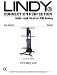
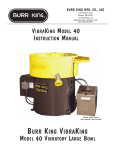
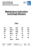
MC520
MOBILE CONVEYOR
Hydraulic Head Fold Fitting Guide
To be read in conjunc on with the MS‐SERIES PRODUCT PARTS USER’S MANUAL
STEP ONE
Remove all items from conveyor;
1.
Axle
2.
Feedboot Extensions
3.
Ballast Box
4.
Head Drum Guard
5.
Coupling Hose Kit
6.
Control Valve Assembly
7.
Head Drum Motor Assembly
8.
Conveyor Support Brace
9.
Main Axle Assembly
10. Wheels
11. Belt Scraper Assembly
STEP TWO
Attach lifting eyes and slings to points highlighted in the below illustration. Fold Head and Tail
Section to operating position. Secure in position with bolts provided.
STEP THREE
Fit Feedboot Assembly to Main Conveyor Tail Section. Once fitted attach Conveyor Side Guards
and Conveyor Rear Guard as illustrated below.
STEP FOUR
During Transport of the MS65, the Wing Rollers of the 9th, 10th and 11th Roller Beds have been
dropped to gain room for storing components. Wing Rollers should be secured at the First Hole of
the First Row. Secure with M8 L-Bolts found in roller bed.
STEP FIVE
Now secure the Head Motor Assembly to the Rigid Coupling. Remove the Side Guards from the
Motor Guard and align the assembly with the Rigid Coupling on the Conveyor head section as
illustrated below. Once aligned, tighten bolts to secure.
Note: Bolts must have lock tight applied
Once secured insert an R-pin here
NB: Grub screws on 40mm and 2 1/2” taperlock must be torqued to 50 Newtons All bearings must be hand greased before grease pots are fi ed Lock ght bolts on Rigid coupling STEP SIX
Once the Hydraulic Head Motor is fitted, remove bungs from hydraulic hosing and reconnect to
Conveyor Head Section Bulkheads as shown in diagram below.
3 1 2 ITEM NUMBER
DESCRIPTION
ORIENTATION
1 Drive (Pressure) at Head to Motor
90+ST 2 Return at Tail to Head
90+ST 3 Bleed at Head to Motor
90+ST STEP SEVEN
Fit Head Drum Guard - (M12X35, 6No. Guard washer showing &
an M12 washer underneath)
Once fitted attached Feedboot Extensions with bolts & nuts
provided (M12 X 35 with M12 Double Washers)
M12X35 BOLTS
Double washer
STEP EIGHT
Fit Wheels and Stubs to Axle Assembly as shown in illustration below. Once fitted lift conveyor
into position ready to attach complete Axle Assembly to undercarriage supports.
STEP NINE
Attach slings and lift Main Conveyor Assembly at points shown in image below. Once in position
move the Main Axle Assembly (136-20-203) into position to fix the Conveyor Support Assembly
(136-30-702), Inner Conveyor Support (139-30-700) and Conveyor Ram Assembly (25-02-0210)
to the Main Axle Assembly
Once secured in position lower the Conveyor so that the Conveyor Supports take the weight,
slacken chains and remove slings.
STEP TEN
Fit Ballast Box Assembly to Conveyor Tail Section. Attach a crane to the Towbar Eye and lift up
only enough to allow the Ballast Box to be manoeuvred into position. Fix in position with bolts
provided.
* Feedboot Extensions not represented in this model
STEP ELEVEN
Fit Conveyor Support Brace Assembly onto Conveyor Support Assembly.
STEP TWELVE
Fit the Two Bank Control Valve with Bracket to Conveyor Tail Section with bolts provided. Once
in place, reconnect hydraulic hosing to Conveyor Bulkheads as showed below.
Hose runs through undercarriage to Main Lift Ram
Ram
(MS65)- 2 hoses for the Ram;
7100mm long 90+90 from valve
Bank to Bulkhead
1450mm 90+90 from Tail Bulkhead
to Ram
Connects to Ram using a 3/4”X
3/8” M/M adapter
STEP THIRTEEN
Once the conveyor is lifted and secured to undercarriage supports, fit the Head Drum Scraper to
Conveyor Head Section as illustrated below. Do not fully adjust Belt Scraper until belt is
tightened correctly.
STEP FOURTEEN
Finally, couple the conveyor to Powersource and run conveyor to check belt alignment. Follow
the instructions set out in your MS-Series Operational manual and illustrations below.