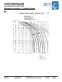
1
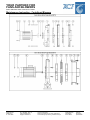
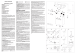
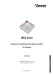
YOUR PARTNER FOR
FANS AND BLOWERS
Steel I Stainless Steel I Aluminium I Plastic
Maintenance Instruction - Centrifugal Blowers
Maintenance Instruction
Centrifugal Blowers
Type:
MN
MSP
MAP
MS
MA
MAR
MAR/S
MHR
MH
MM
MB
MBS
MBQ
CA
GR
RL
MRLQ
RM
RU
VM
VC
VA
VP
VG
VI
ZM
ZD
ZC
ZA
ZB
BSTS
MSTS
…
ACF Ventilatoren GmbH
Registered office
Elf Stücken 21
D - 49324 Melle
Phone: +49(0)5422 - 9895 - 0
Fax: +49(0)5422 - 9895 - 15
www.acf-ventilatoren.de
[email protected]
VAT (ID) Number: DE 814776828
Tax-No.: 65/200/18329
District Court Osnabrück Com.-Reg.: HRB 200792
General Manager: Dipl.-Wirt.-Ing. Kristiaan Swaczyna
Axial Fans
Centrifugal Blower
ATEX-Blower
400°/2h Blower
Roof Fans
Wall Fans
Pipe Blower
Special Blower
YOUR PARTNER FOR
FANS AND BLOWERS
Steel I Stainless Steel I Aluminium I Plastic
Maintenance Instruction - Centrifugal Blowers
1.
PREAMBLE
Thank you very much for having purchase a ACF Ventilatoren GmbH (hereinafter referred to as ACF) product. The information you can
find in this user manual can not be used for any purpose other than the one for which the user manual has been drawn up. The
publication and documentation which have been supplied with the fan can be reproduced neither partially nor totally without ACF’s
written consent. The schematic drawings and illustrations representing the machine are only understood as a didactic reference. The
content of this manual can be modified by ACF without any prior notice and without incurring any sanction.
2.
INTRODUCTION
The Centrifugal fans can be single aspiration or double aspiration type, in any case the air enters in the impeller with axial direction and
leaves with tangent to blades plan direction. Fans are intended to move clean air volumes or air mixed with dusts or particles of variable
granulometry by means of channels or pipelines according to the use conditions described by ACF catalogues and summed up by
the table on page 3. Any unintended use is forbidden. The main components and eventual accessories are brought back in point 22 of
this manual (Parts Lists). The fans but exceptions are paint by epoxy powder varnishes having anti-oxidant function. Fans are supplied
with MEC standardised 2, 4, 6 or 8 pole motors.
Guarantee:
ACF guarantees its own fans for a period of 12 months starting from the delivery date. The guarantee shall be understood as limited to
the sole replacement of any component or accessory which is held to be defective by ACF as a result of its false assembly or
manufacture. Any other responsibility and obligation for any direct or indirect expense, damage and loss deriving from the use or from
the total or partial impossibility of using the fan is excluded. The repair in guarantee and the restitution of the product are understandings
as ex our factory. Therefore every transport cost or pack inherent to the same repair are to cargo of the purchaser.
Varying SV and SW (Suitable for Warm Gases):
In order to dissipate part of the heat which had to the warm gas presence, between the motor and the case of the fan, an aluminium
fusion cooling impeller, opportunely protect by metallic grill. Such cooling impeller, in function of the type and/or model of fan in
examination, it can be fastened directly on the motor shaft or on the extended impeller hub.
3.
IDENTIFICATION PLATE
In case of demand for assistance, always make reference to the data brought back on the nameplate.
The fans that do not bring back on the nameplate “CE”, must be complete from the purchaser who will have to then certify all
the system.
the fans that work in a potentially explosive atmosphere in compliance with the Directive "ATEX" 94/9/CE, are identify with a
nameplate bringing back the following indications:
□
□
□
□
□
□
Manufacturer’s name and address
Type and series identification
Manufacturing year
CE mark
Ex symbol inside a hexagon
ATEX string reporting symbol declaring explosion risk and:
- Group (ex. II: equipment meant for surfaces and sites other than the mine)
- Zone (ex. 2: high protection level)
- Category (ex. G: protection against a potentially explosive gas)
- maximum fan surface temperature class (ex. T3)
ACF Ventilatoren GmbH
Registered office
Elf Stücken 21
D - 49324 Melle
Phone: +49(0)5422 - 9895 - 0
Fax: +49(0)5422 - 9895 - 15
www.acf-ventilatoren.de
[email protected]
VAT (ID) Number: DE 814776828
Tax-No.: 65/200/18329
District Court Osnabrück Com.-Reg.: HRB 200792
General Manager: Dipl.-Wirt.-Ing. Kristiaan Swaczyna
Axial Fans
Centrifugal Blower
ATEX-Blower
400°/2h Blower
Roof Fans
Wall Fans
Pipe Blower
Special Blower
YOUR PARTNER FOR
FANS AND BLOWERS
Steel I Stainless Steel I Aluminium I Plastic
Maintenance Instruction - Centrifugal Blowers
4.
WORKING CONDITIONS AND CHARACTERISTICS
Series
MN
MSP
MAP
MS
MA
MAR
MAR/S
MHR
MH
MM
MB MBS
MBQ CA
GR
RL
MRLQ
RM
RU
VM VC
VA
VP
VG VI
ZM ZD
ZC ZA
ZB
MSTS
BSTS
Working conditions and characteristics t
MN blowers are particularly suited for cooling D.C. motors, lamps, extruders, etc., to extract fumes and gasses and in
all applications that require moving large volumes of channelled air.
MSP blowers are particularly suited for cooling D.C. motors, lamps, extruders, etc., to extract fumes and gasses and
in all applications that require moving large volumes of channelled air.
MAP blowers are particularly suitable for machines that work plastic materials and sandblasting machines.
MS blowers are particularly suited for exhaust gas suction and for automatic machine and plastic material industry and
granulator.
MA blower are particularly suited for blowing clean air or air containing quantities of dust up to a maximum
temperature of 90°C. This series may be used in industrial systems which require a relatively small flow-rate with highpressure such as for example: liquid fuel burners, pneumatic conveyor-systems, etc.
MAR blowers are particularly suited to blowing clean air of air containing small quantities of dust up to a maximum
temperature of 90°C. They may be used in the glass-working industry, in the textile and chemical industry.
MHR blowers are particularly suited to blowing clean air or air containing small quantities of dust up to a maximum
temperature of 90°C. They may be used in industrial plant applications where a relatively small flow-rate with high
pressure is required, such as: blowing nozzles, very long pipe runs, pneumatic conveyor systems, etc.
MM blowers are particularly suited for blowing air and fumes, even containing small quantities of dust up to a
maximum temperature of 90°C. They may be used in domestic and industrial ventilation systems.
MB blowers are particularly suited to blowing air or fumes even containing small quantities of dust up to a maximum
temperature of 80°C. They are widely used in domestic or industrial ventilation, heating and air conditioning systems.
High capacities, medium-high pressures. They may be used for pneumatic conveyance, gasses, granulated
materials. Suitable for the transport of solid materials mixed with air, sawdust and woodchips if fan is not crossed.
Standard execution for air temperature up to 60°C, special execution for higher temperatures
Very high capacities, low pressures. They may be used for the suction of clean or slightly dusty air and the most
various uses in the industrial field and for uses civil and industrial air conditioning systems. Standard execution for air
temperature up to 60°C, special execution for higher temperatures.
High capacities, medium pressures. They may be used for suction and transport of air, sawdust, woodchips,
granulated materials with the exclusion of fibrous materials. Standard execution for air temperature up to 60°C, special
execution for higher temperatures.
High capacities, medium pressures, high performances. They may be used for suction and transport of air, pneumatic
transport, drying systems, sawdust, woodchips, granulated materials with the exclusion of fibrous materials. Standard
execution for air temperature up to 60°C, special execution for higher temperatures.
Medium and low capacities, high-pressures. They may be used for the pneumatic conveyance, gasses, granulated
materials. Suitable for the transport of solid materials mixed with air, sawdust, and woodchips if the fan is not crossed.
Standard execution for air temperature up to 60°C, special execution for higher temperatures.
Low capacities, high-pressures. They may be used for the pneumatic conveyance, dirty air, drying systems.
Particularly suitable for foundries, food and chemical industry. Standard execution for air temperature up to 60°C,
special execution for higher temperatures.
Medium and low capacities, high-pressures. They may be used for the pneumatic conveyance, dirty air, drying
systems. Particularly suitable for foundries, food and chemical industry. Standard execution for air temperature up to
60°C, special execution for higher temperatures.
Medium and low capacities, high-pressures. They may be used for the pneumatic conveyance, dirty air, drying
systems. Particularly suitable for foundries, food and chemical industry. Standard execution for air temperature up to
60°C, special execution for higher temperatures.
Low capacities, medium-high pressures. They may be used for the pneumatic conveyance of solid materials mixed
with air, sawdust and woodchips; particularly suitable for fibrous materials that could clog a reverse type impeller of
normal construction. Standard execution for air temperature up to 60°C, special execution for higher temperatures.
MSTS blowers have been devised specifically for use in garment pressing sectors on an industrial scale (with
centralised systems for one or more presses) and are just as suitable for supplying ovens and burners where constant
air pressure determines the good functioning of the system.
BSTS blowers are particularly suitable to treat clean air or fluids; if it should work in dusty environments it is better to
equip it with an inlet filter.
ACF Ventilatoren GmbH
Registered office
Elf Stücken 21
D - 49324 Melle
Phone: +49(0)5422 - 9895 - 0
Fax: +49(0)5422 - 9895 - 15
www.acf-ventilatoren.de
[email protected]
VAT (ID) Number: DE 814776828
Tax-No.: 65/200/18329
District Court Osnabrück Com.-Reg.: HRB 200792
General Manager: Dipl.-Wirt.-Ing. Kristiaan Swaczyna
Axial Fans
Centrifugal Blower
ATEX-Blower
400°/2h Blower
Roof Fans
Wall Fans
Pipe Blower
Special Blower
YOUR PARTNER FOR
FANS AND BLOWERS
Steel I Stainless Steel I Aluminium I Plastic
Maintenance Instruction - Centrifugal Blowers
5.
WARNING
Safety precautions and instructions
□
All exposed people shall strictly follow the safety and accident prevention rules in force.
□
The fan user shall make sure that all the instructions given by this user manual are scrupulously and unmistakably followed.
□
The fan may be only installed by properly trained and qualified personnel.
□
Service or repair operations may be only carried out by skilled personnel in compliance with the instructions given by this manual.
□
Before carrying out any maintenance and/or regulation operation, disconnect the fan from its power supply sources.
□
Any change to the fan may be only made by the personnel who have been authorised by ACF
□
While connecting or disconnecting the power supply cable, make sure that the earth wire is always the first and the last wire
which is respectively connected and disconnected;
□
Lend attention to the tags placed on the fan.
□
Never expose the fan to water jets.
□
Safety protections shall never be removed. If absolutely required, it is necessary to take any measure promptly in order to point
out any possible danger. Protections shall be restored as soon as the reason for their temporary removal has ceased to exist.
□
It is absolutely forbidden to provide for a makeshift connection.
□
Never use the fan for any unintended purpose.
□
Before operating the fan, make sure there is no dangerous condition.
□
Never start the fan if the inspection door has not been put back into its position and locked by means of bolts.
□
Before opening the inspection door, make sure that the rotating parts are not moving and that the electric line is not live.
□
If the suction and/or outlet mouths are not canalised, provide for the arrangement of a proper protection net or grille.
□
It is forbidden to service, clean or repair the fan when it is working (moving).
□
It is absolutely forbidden to use your hands or your tools in order to try to brake any rotating member and to accelerate their stop.
□
If the machine is equipped with a pulley, stop the machine before moving the belt manually in order to change the speed rate.
□
Never leave any material in the proximity of any piece which can be either rotated or operated.
□
In case of a power failure, promptly disconnect the main switch of the machine.
□
Always use protection gloves, masks and glasses to clean.
□
The fans shall be stored in a closed place where there is no dust and where humidity will never exceed 80%;
□
Never store the fan in the proximity of any machine which may produce vibrations. Otherwise, the bearings will support the same
type of stress.
Personnel selection and qualification
□
Service or repair operations shall be carried out by skilled personnel in compliance with the instructions given by this manual.
□
Spare parts may be only replaced by qualified personnel.
□
The fan may be installed and operated for the first time by properly trained and qualified personnel.
□
The fan may be only handled by qualified personnel in compliance with the safety rules in force by means of a fork lift or crane.
Clothing
□
It is very important not to underestimate the dangerousness of any rotating part. Any fluttering garment may get caught up and
drag the person wearing the garment against the machine.
Safety rules for use, maintenance and repair
□
Before operating the machine, make sure that all eventual metal chips and tools used to clean the machine have been removed
from the scroll.
6.
ACCIDENT PREVENTION DEVICES
The range of ACF fans is complete with accident prevention apparatuses and accessories on different rotating parts, in compliance
with UNI 10615 standards, and namely:
□
protection nets absolutely indispensable which shall be installed on the suction and pressing mouths if they are not canalized (to
demand upon the order in how much ACF cannot know where they will be installed the own products);
□
protection case of the cooling impeller;
□
protection guard for pulleys, the belts and shafts of driven fans.
□
In the case in which the fans are not canalized, it will have be to cure of the user to preview the opportune systems that they
prevent to the access to the inside of the fan of strangers things who could damage it.
□
Before starting the fan, make sure that all protections have been properly installed.
ACF DISCLAIMS ALL RESPONSIBILITY FOR ANY DIRECT AND INDIRECT ACCIDENT TO THINGS OR PERSONS CAUSED BY
THE ABSENCE OF SUCH ACCIDENT PREVENTION DEVICES
7.
Noise
The noise levels values of ACF fans are expressed in decibel scale A (dB/A) and are obtained by taking the measurements on a free
field, at the maximum efficiency level, on the 4 cardinal points, 1.5 m. far from the fan. The fan is canalised in compliance with the UNI
10531 standards during the test. The values which have been measured are specified by ACF catalogues. They can be different from
ACF Ventilatoren GmbH
Registered office
Elf Stücken 21
D - 49324 Melle
Phone: +49(0)5422 - 9895 - 0
Fax: +49(0)5422 - 9895 - 15
www.acf-ventilatoren.de
[email protected]
VAT (ID) Number: DE 814776828
Tax-No.: 65/200/18329
District Court Osnabrück Com.-Reg.: HRB 200792
General Manager: Dipl.-Wirt.-Ing. Kristiaan Swaczyna
Axial Fans
Centrifugal Blower
ATEX-Blower
400°/2h Blower
Roof Fans
Wall Fans
Pipe Blower
Special Blower
YOUR PARTNER FOR
FANS AND BLOWERS
Steel I Stainless Steel I Aluminium I Plastic
Maintenance Instruction - Centrifugal Blowers
those which can be measured on the plants, according to environmental installation and operation conditions. To reduce the noise level,
it is recommended to insulate the fan from the ground and canalisation by means of vibration-damping supports and sucking flexible
joints.
8.
BALANCING
All the impellers of ACF fans are statically and dynamically balanced before the assembly in compliance with the ISO 1940/1 standard.
The balancing degree is equal to 6,3.
9.
□
□
□
PACKAGE, TRANSPORTATION AND HANDLING
If the fan is not packed, close the suction and outlet mouths to prevent any dirty and/or foreign body from penetrating inside.
Never use the shaft, the motor or the impeller to bring up the fan.
For particularly long and bumpy distances, block the impeller in order to avoid damages to the bearings of the motor and
balancing problems of the rotary parts
Follow these simple rules to lift a fan correctly:
A)
Keep your body in a balanced position and bend your knees to lift the material.
B)
Hold yourself upright and keep your arms rigid.
C)
Take the fan with the palm of your hands by keeping your feet at a certain distance to ensure the stability of your body.
D)
The effort shall be mainly supported by your lower limbs during the lifting.
E)
Keep the fan leaning against your body during the transportation by distributing the weight on your arms without swinging.
F)
Never transport the fan when your hands are filthy.
G)
Never forget to use proper protection devices: gloves and shoes.
Handling by means of a fork lift or crane
The fan shall be handled by qualified personnel in compliance with the rules in force by means of a fork lift or crane. Before moving a
fan, make sure that the means has got a correct capacity. When handling the fan, never exceed the carriage capacity limits. The main
risks relative to the lift trucks used to move the fans are due to:
a)
The truck operator’s imprudence;
b)
The falling down of the fan when it is either transported or stacked;
c)
The turning over of the means when the speed is too high or the fan is too heavy.
The carriage is a means manufactured to move on flat surfaces; Any flooring with holes or bumps is very dangerous. If the way should
be either sloping or winding or if the road surface should be irregular, it is absolutely necessary to avoid any sharp starting or braking in
order to prevent the means from turning over.
The maximum height of the fan shall be such that the head of a person of average height in front of the carriage can be seen from the
driver’s seat. If the fan should be so high that your view is blocked, go into reverse or let an operator go before the carriage and signal its
presence.
If a fan is transported by means of a fork lift, make sure that the heaviest and lightest part is respectively at the bottom of the forks and
the points. Never leave the fan hanging in the air.
To lift a fan by means of a rope or fork crane, use the hooking points only. Never forget to distribute the load uniformly. Handling shall
occur with the utmost care. Avoid any crash which might compromise the correct operation.
10.
INSTALLATION
□
The first starting must be of short duration for the control of the direction of rotation parts. For direct drive fan, the direction of
rotation can be controlled on the electric motor. compare the direction of rotation with the arrow (adhesive) being on the ventilator
or on the plate. If it is not the same, detach the fan from the power supply and reverse the phase in the motor;
Before installing the fan, make sure that the fan has not been damaged during its transportation and that the inspection door has
been closed. Make sure that there is no foreign body inside and that all bolts have been firmly tightened; make sure that the
rotating parts can move freely.
If the fan should be either supplied or shipped before its assembly for any reason whatsoever (transportation, etc.), follow the
instructions, diagrams and drawings given by this manual for a correct assembly which shall be performed by qualified personnel.
For the connection to the motor terminal box, strictly follow the wiring diagrams shown by point 23 of this manual.
□
□
□
ACF Ventilatoren GmbH
Registered office
Elf Stücken 21
D - 49324 Melle
Phone: +49(0)5422 - 9895 - 0
Fax: +49(0)5422 - 9895 - 15
www.acf-ventilatoren.de
[email protected]
VAT (ID) Number: DE 814776828
Tax-No.: 65/200/18329
District Court Osnabrück Com.-Reg.: HRB 200792
General Manager: Dipl.-Wirt.-Ing. Kristiaan Swaczyna
Axial Fans
Centrifugal Blower
ATEX-Blower
400°/2h Blower
Roof Fans
Wall Fans
Pipe Blower
Special Blower
YOUR PARTNER FOR
FANS AND BLOWERS
Steel I Stainless Steel I Aluminium I Plastic
Maintenance Instruction - Centrifugal Blowers
NOTE
The electric equipment previewed by the user should include:
fuses, voltage overload and fall protections chosen to fit the effective
starting time and the full load current. Detect the absorbed current on
one of three line conductors L1 L2 L3. In the connection Υ Δ the
reading must be done before the commutator. If this is not possible,
detect the phase current on any of the six conductors and multiply the measured value by 1,73.
The user should earth the fan (!!!! Check the earth connection)
11.
ENVIRONMENT
The use of the fan will require no special lighting source in compliance with the UNI EN 10380 standards. The available light is enough.
12.
MINIMUM SPACE FOR USE AND MAINTENANCE
Place the fan in such a way that a minimum space is guaranteed for service and repair operations.
13.
BASES AND STRUCTURES OF SUPPORT
□
The flatness and sturdiness of the surface intended to support the fan static and dynamic load. For elevated performances fans, it
is advised to use reinforced concrete slabs.
If the fan comes supported on a metallic structure, lend attention to the fact that this is sufficiently rigid to support the double
quantity of the weight of the fan.
It is recommended to place vibration-damping members (vibration-damping supports and joints which have been properly
dimensioned) between the fan and the interfaces (floor and foundations). The supports shall not be completely crashed and they
should support a basic rame instead of single frame elements (however, it is advisable to consult ACF for their selection).
□
□
LEVELLING: It is very important to level the structure intended to support the fan in order to avoid noxious vibrations and foreign noises.
14.
POWER SUPPLY AND ELECTRIC CONNECTION
□
□
Make sure that the voltage and frequency specified by the fan plate and/or electric motor will correspond to the operation voltage
and frequency of the plant in use.
Connect the fan with a plant in accordance with the law by means of a differential switch (ground fault interrupter).
The minimum cross section of electric connection cables shall be chosen on the basis of voltage, the power installed and the
distance etween the source and use.
All electric connection cables shall be connected in such a way that they can be neither torn nor damaged.
15.
COMMISSIONING/TESTING
□
□
Make sure that all bolts are firmly tightened after a one-hour operation. If necessary, repeat the tightening process.
It is good practice to check the current absorbed by the motor. Its value shall be lower than the motor rating value.
16.
START/OPERATION/STOP
□
□
Before starting the fan, it is necessary to:
□
Make sure that all the bolts and nuts are firmly tightened. Special attention shall be paid to the fastening screw of the impellerb on
the motor shaft and its supports.
□
Make sure that the impeller will rotate freely (use your hands to rotate it).
□
Avoid starting the fan consecutively. This will involve continuous overloads which will overheat the electrical parts. Before
restarting, let the motor cool down.
□
It always must be previewed from 5,5 kW up, star-delta connection or inverter or other type of gradual starting;
□
The fans may have very long starting times and absorption peaks as high as the maximum multiplier of the rated amperes of the
electric motor; therefore, the whole electric system must be dimensioned according to the starting times and peak absorption
levels.
□
After some working hours, check that vibrations have not loosened the tightening of bolts and nuts or changed the tension of
belts
17.
MAINTENANCE/INSPECTIONS/CHECKS
□
Before carrying out any service operation, make sure that the fan has been electrically disconnected that all moving parts are not
working.
Check the painted metal structures at least once a year in order to prevent any corrosion phenomenon.
□
ACF Ventilatoren GmbH
Registered office
Elf Stücken 21
D - 49324 Melle
Phone: +49(0)5422 - 9895 - 0
Fax: +49(0)5422 - 9895 - 15
www.acf-ventilatoren.de
[email protected]
VAT (ID) Number: DE 814776828
Tax-No.: 65/200/18329
District Court Osnabrück Com.-Reg.: HRB 200792
General Manager: Dipl.-Wirt.-Ing. Kristiaan Swaczyna
Axial Fans
Centrifugal Blower
ATEX-Blower
400°/2h Blower
Roof Fans
Wall Fans
Pipe Blower
Special Blower
YOUR PARTNER FOR
FANS AND BLOWERS
Steel I Stainless Steel I Aluminium I Plastic
Maintenance Instruction - Centrifugal Blowers
□
□
□
□
□
□
It is recommended to make sure at regular intervals, i.e. every four months, that all bolts are firmly tightened Special attention
shall be paid to the fastening screw of the impeller on the motor shaft.
it is advisable to constantly verify the impeller to ensure that it is kept clean. If material, dust, greasy substances etc. are allowed
to build up on the rotor, it will become unbalanced, thereby causing damage to the driving members and/or electric motor. When
cleaning the rotor, make sure you thoroughly clean every single part; residues left in confined spots may cause more unbalancing
than a uniform layer of dirt.
If the impeller is encrusted, clean it carefully in all its parts. Use a metal brush and an aspirator to remove all the material.
If it is necessary to remove the impeller, act as follows:
Loosen the bolts (or nuts) intended to fasten the nozzle to the fan side and remove it.
Remove the screw and the washers intended to fasten the impeller to the motor shaft. Use an extractor to remove the
impeller from the shaft.
Act in the reverse order for the assembly.
The electric motors assembled on the fans require no special maintenance since the bearings are lubricated for life;
In a fan, the only programmed maintenance operations concern the lubrification of bearing (if these are not proof) and the
verification of the corrected tention of the belts.
Lubrication
□
The ACF fan blocks contain bearings provided with a grease cup; ACF delivers the fans already adequately lubrificated and
ready for operation. The lubrication times tfa for radial ball bearings, tfb for straight roller bearings and tfc for revolving roller
bearings can be drawn from diagram (page 53) as a function of the rotational speed n of the bearing and of the diameter d of is
hole. The diagram is valid for bearings of horizontal shafts and in the presence of normal loads. It can be applied to good quality
lithium greases at a temperature not higher than 70°C. Because of the rapid ageing of the grease following an increase in
temperature, we recommend to halve time intervals every 15°C increase in the working temperature of the bearing, but still
without never exceeding the maximum admissible temperature for the grease (see the table).
□
ACF recommends using grease of the type: SKF LGEP 2;
□
If the block or support is protected by a guard, make sure that you replace the protective plastic plugs in the openings providing
access to the grease cups.
□
ACF fans are dimensioned so to guarantee a bearing life of 20.000/30.000 hours of continuous operation. However this warranty
is valid only for drives calculated and installed at our factory;
Type of grease (Thickening
Lithium base
Complex lithium
Sodium base
Complex sodium
Calcium base
Complex calcium
Complex barium
Complex aluminium
Inorganic thickening agents (bentonite, silica gel, etc.)
Polyurea
Recommended operation from °C
-30
-20
-30
-20
-10
-20
-20
-30
-30
-30
Temperature rangeto °C
+110
+140
+ 80
+140
+ 60
+130
+130
+110
+130
+140
Application mode:
Clean the attachment of the grease cup. The addition of grease is to be performed by making the shaft rotate slowly without exceeding
the quantity to avoid overheating. The amount of grease to be introduced can be determined by this formula:
P = 0,005 A B (gr) where
A=
external diameter of the bearing in mm and
B=
length of the ring in mm
If high pressure grease cups are used, these should be accurately cleaned after their use.
Cleaning the impeller
It is absolutely necessary to control the cleanliness of the impeller. Every type of dirt may cause an unbalance of the impeller which could
lead to the destruction of the shaft of the motor or of the pedestal bearing. If you clean the impeller you have to clean it very accurate
because some dirt just on a part of the impeller is even more dangerous than a uniform dirt coat. ACF takes no responsibility for any
damage of the blower due to the improper service to the impeller.
Assembly/Disassembly of the drive and tensioning of belts
For the assembly and tensioning of belts, it is necessary to keep to the sequence of the following steps with the help of drawing (see
appendix):
1.
Preassemble the motor with the provided slides and threaded drawplates by securing it by securing it by means of bolt 1without
tightening. The motor, as well as the driven shaft, must have the pulley already installed and carefully stopped at 20-25 mm
from the beat of the shaft to allow the following easy positioning of the protection guard.
2.
Position the unit on the bed and secure the slides to it. Before this operation, it is necessary to check the alignment of pulley. A
practical method could be the utilisation of a ruler which has to lay uniformly on the external face of both pulleys.
ACF Ventilatoren GmbH
Registered office
Elf Stücken 21
D - 49324 Melle
Phone: +49(0)5422 - 9895 - 0
Fax: +49(0)5422 - 9895 - 15
www.acf-ventilatoren.de
[email protected]
VAT (ID) Number: DE 814776828
Tax-No.: 65/200/18329
District Court Osnabrück Com.-Reg.: HRB 200792
General Manager: Dipl.-Wirt.-Ing. Kristiaan Swaczyna
Axial Fans
Centrifugal Blower
ATEX-Blower
400°/2h Blower
Roof Fans
Wall Fans
Pipe Blower
Special Blower
YOUR PARTNER FOR
FANS AND BLOWERS
Steel I Stainless Steel I Aluminium I Plastic
Maintenance Instruction - Centrifugal Blowers
3.
Introduce the belts without forcing to avoid tearing of the fibres of the internal frame. Thus, to allow an easy installation, it is
recommended to reduce the distance between the driver and the driven pulley by adjusting the tension of the tightener (slides
for execution 12, tipper inclination for execution 9).
Adjust the tightening drawplates by means of nuts 2. The possible misalignment of the two slides as compared to the central
line is to be corrected on one or the other drawplate and then checked as for the correct positioning as described at poin 2.
Then tighten by means of nuts 1.
4.
5.
For fans in execution 9, the above-mentioned points are the same except for slides which are not necessary with this kind of
solution.
To assure a regular drive by reducing in particular the bearing wear, it is suitable to consider the following factors when belts are to
be replaced:
□
The ideal tension is the lowest tension at which the belt does not slip under maximum load conditions.
□
Check frequently the tension during the first 24/48 hours of running in.
□
An over-tensioning reduces the operational life of belt and bearing.
□
Check periodically the drive by tensioning it when it slips.
To check the tension in a conventional drive, it is recommended to keep to the following procedure:
□
Measure the length of the free section ‘t’.
□
In the middle of the free section ‘t’ apply enough force (Td) by means of a dynamometer perpendicular to the free section, to bend
the belt by 1.6 mm every 100 mm of length of the free section. For ex., the bending of a 1000 mm free section will be 16 mm.
□
Compare the values of applied force with the recommended values of the table. If the force value is between maximum and
minimum, then the drive tension is correct. A force value lower than the minimum one, indicates an under-tensioned drive. A
force value higher than the maximum one, indicates an over-tensioned drive.
BELT
SECTION
A
B
C
FORCE
Minimum kg
Maximum kg
0,68
1,02
1,58
2,38
2,93
4,75
Replacing the belts
□
Owing to natural wear and tear the belts will need to be replaced with a frequency depending on the running conditions.
□
To dismantle the belts first of all remove the transmission guard,
□
then release the screws for the motor,
□
and turn the adjustment screws to reduce the distance between the motor pulley and the fan pulley.
□
At this point it is possible to change the belts installing new belts of the same type.
□
Turning the adjustment screws bring back the motor and check the tension of the belts as previously explained, and then fasten
the motor onto the stretchers.
□
Refit the belts guard and fully tighten the bolts.
Replacing the pulleys
□
It is important to periodically check the state of the channels in the pulleys and, if necessary, to change them.
□
It is important to note that the tension of the belts, and the alignment of the transmission are significant factors in prolonging the
life of the pulleys.
□
The pulleys with conical bush are replaced as follows:
□
release the three screws and insert one of them in the free hole; turn the screw in until the complete unlock
□
clean the bush shaft support with a cloth but don’t grease it
□
mount the pulley on the fan shaft
□
insert the bush in the pulley taking care that the threaded half holes of the pulley coincide with the nonthreaded half holes of the
bush
□
put and tighten the three screws evenly and alternating between them until the pulley is fully fastened
□
check that the pulleys are statically and dynamically balanced.
18.
DISABLING THE FAN
The fans and/or its components shall be dismantled, i.e. “scrapped”, in compliance with the local rules in force. Apply to town dump sites
or companies for waste disposal.
19.
SPARKPROOF EXECUTION
It is absolutely necessary to consult preventively ACF before using any fan in potentially explosive atmospheres. Fans manufactured and
dealt by ACF S.r.l can be used in potentially explosive atmospheres, in compliance with ATEX 94/9/CE Directive only behind explicit
indication of the manufacturer, after risk assessment and compilation (by customer) of a specific questionnaire; in this case, ATEX string
ACF Ventilatoren GmbH
Registered office
Elf Stücken 21
D - 49324 Melle
Phone: +49(0)5422 - 9895 - 0
Fax: +49(0)5422 - 9895 - 15
www.acf-ventilatoren.de
[email protected]
VAT (ID) Number: DE 814776828
Tax-No.: 65/200/18329
District Court Osnabrück Com.-Reg.: HRB 200792
General Manager: Dipl.-Wirt.-Ing. Kristiaan Swaczyna
Axial Fans
Centrifugal Blower
ATEX-Blower
400°/2h Blower
Roof Fans
Wall Fans
Pipe Blower
Special Blower
YOUR PARTNER FOR
FANS AND BLOWERS
Steel I Stainless Steel I Aluminium I Plastic
Maintenance Instruction - Centrifugal Blowers
(characterized and/or indicated by the customer) composed by (protection against the declaring explosion risk), equipment belonging
Group, Zone of use, Category (protection from the potentially explosive type of gas or powder) and maximum fan surface temperature
class will be present on the identification name plate of the fan. It is forbidden to use ACF fans for uses and in atmospheres different from
the one previewed upon the order; ACF S.r.l declines every whichever responsibility for direct or indirect damages to persons or things
coming from improper use of such equipment.
Fans manufactured in compliance with ATEX 94/9/CE Directive are suitable to convey of flammable and combustible substances
(verified by ACF and based on data supplied by the customer) and they have been designed for use in atmosphere characterized by
temperature included between -20 and 40° C, 80% relative humidity, in classified zone as 1/21 and 2/22 (respectively for equipment
categories 2G/D and 3 G/D); they are manufactured in various executions, using parts which may potentially come into contact one with
each-other with potentially rubbing risk made by non ferrous materials in compliance with the 94/9/CE - ATEX directive; the fan in object,
should be considered like a component; therefore mention of prohibition of putting on service before having assured that the machine
and/or the system inside of which it has been incorporated has been put in safety from the point of view of explosion risk before being
started, and it has been declared in compliance with the dispositions of according to ATEX 94/9/CE Directive is done.
Atmosphere
Gas, Mixture or
Dust Presence
Zone
Level of danger during normal servic
0*
Always Present Explosive Atmosphere (Permanent Danger)
1
Probable Explosive Atmosphere (potential Danger)
2
Barely Probable Explosive Atmosphere (Minimal Danger)
Dust
20*
Always Present Explosive Atmosphere (Permanent Danger)
Presence
21
Probable Explosive Atmosphere (potential Danger)
22
Barely Probable Explosive Atmosphere (Minimal Danger)
*ACF does not construct blowers for category 1G and 1D for zones 0 and 20.
Category
1G*
2G
3G
1D*
2D
3D
Fans declared in compliance with ATEX 94/9/CE Directive have been designed, manufactured and tested in order to work in conditions
of emergency with powders and gas or vapours having ignition temperature higher than 250° C, as indicated on the name plate and on
the conformity declaration.
□
Install the explosion-proof fan by leaving about 1 m from any other equipment installed in the proximity in order to enable the
operator to provide inspection and control and to prevent the fan from rubbing with any other body installed in the proximity;
□
Explosion-proof fans shall be installed on plants or structures with reduced to minimum stresses;
□
Prevent explosion-proof fans from striking any metal material and device in explosive environments;
□
Use only explosion-proof tools for assembly and maintenance;
□
In order to avoid powder deposit, clean the outside of the fan and the protection grid at regular intervals. Clean the impeller
without using any metal brush. Use wet antistatic clothes and explosion-proof aspirators to prevent the dust from building up;
□
It is recommended to use spark-proof tools for the maintenance of explosion-proof fans;
□
It is forbidden to expose the explosion-proof fan to any environment where any electromagnetic field is present;
□
It is also recommended to install a lightning conductor in the proximity of the room where the fan is used in order to avoid any
excess current phenomenon;
□
Paint the case at regular intervals (periodicity will be related to the features of the room where the fan is used) in order to avoid
any corrosion phenomenon that might compromise the explosion-proof character of the fan whenever the latter is hit by ferrous
materials (use paintings with epoxy-polyester or polyester powders).
□
Never lubricate the seal. Oil or grease presence in potentially explosive atmosphere may be danger cause;
Note: cleaning operations intervals are closely related to the type of transported fluid and its concentration; it is therefore necessary that
the final user determines a cadence of cleaning operations so that the impeller is always perfectly cleaned up (deposited material
on rotating parts cause unbalance) and that deposits of material on the fixed parts over 5 mm of thickness do not stratify; The
minimum distances between any metallic rotating and any metallic stationary part must always be advanced to 1% of the
diameter of the impeller and never shall be inferior to 2mm and superior to 20 mm.
□
User must electrically connect the fan to the ground.
20.
ACCESSORIES
For centrifugal fans, according to the models and compatibly with the characteristics of machine and/or system inside of which they will
be mounted, following accessories are available:
□
Square / Round Connection (it can be used to change the outlet flange from a squared or rectangular section into a circular one);
□
Inspection Door
□
Round / Round Connection or Non Flanged Suction Connection: it can be used to join the fan with any canalization pipeline
□
Complete casing welding
□
Suction Filter
□
Mechanical easy Seal on motor shaft
□
Basement for electrical motor support (for the fans of the MN, AP, MS etc. series used when the arrangement on the target
machine requires additional supports)
□
Noises reducer on suction or on outlet mouth
□
Damper (applicable on suction or on outlet in order to reduce flow rate and/or pressure of the fan
□
Integral Box
ACF Ventilatoren GmbH
Registered office
Elf Stücken 21
D - 49324 Melle
Phone: +49(0)5422 - 9895 - 0
Fax: +49(0)5422 - 9895 - 15
www.acf-ventilatoren.de
[email protected]
VAT (ID) Number: DE 814776828
Tax-No.: 65/200/18329
District Court Osnabrück Com.-Reg.: HRB 200792
General Manager: Dipl.-Wirt.-Ing. Kristiaan Swaczyna
Axial Fans
Centrifugal Blower
ATEX-Blower
400°/2h Blower
Roof Fans
Wall Fans
Pipe Blower
Special Blower
YOUR PARTNER FOR
FANS AND BLOWERS
Steel I Stainless Steel I Aluminium I Plastic
Maintenance Instruction - Centrifugal Blowers
□
Inlet Counter Flange and Outlet Counter Flange
□
Insulated housing or. motor plate
□
Inlet Flexible Joint - Outlet Flexible Joint
□
Anti vibration mounting
□
Multiple connections on inlet and outlet flange
□
Drain plug
□
etc.
Our possibilities are tremendously. We try to meet your technical requirements.
ACF Ventilatoren GmbH
Registered office
Elf Stücken 21
D - 49324 Melle
Phone: +49(0)5422 - 9895 - 0
Fax: +49(0)5422 - 9895 - 15
www.acf-ventilatoren.de
[email protected]
VAT (ID) Number: DE 814776828
Tax-No.: 65/200/18329
District Court Osnabrück Com.-Reg.: HRB 200792
General Manager: Dipl.-Wirt.-Ing. Kristiaan Swaczyna
Axial Fans
Centrifugal Blower
ATEX-Blower
400°/2h Blower
Roof Fans
Wall Fans
Pipe Blower
Special Blower
YOUR PARTNER FOR
FANS AND BLOWERS
Steel I Stainless Steel I Aluminium I Plastic
Maintenance Instruction - Centrifugal Blowers
21.
MALFUNCTIONS, FAILURES, MISCELLANEOUS
The analysis of the failure modes are summed up by the following table:
FOUND OUT EFFECT
Lack of flow rate
Excessive air flow rate
Insufficient pressure
Difficult start
The power input is higher than
the value specified by the motor
rating plate
Excessive noise level
CAUSES
□ Clogged suction points and/or pipelines.
□ Insufficient rotation speed.
□ Working pressure higher than the design
pressure.
□ Clogged impeller.
□ Wrong (reverse) direction of rotation.
□ Overloaded filter.
□ Section changes, sharp and close bends.
□ Sudden expansions or elbows preventing
the user from restoring the delivery dynamic
pressure.
□ Rotation speed.
□ Excessive estimate of the circuit flow
esistance values.
□ The rotation speed is too low.
□ The capacity is higher than the design
capacity since the circuit is not properly
dimensioned or because the air
temperature is considerably different from
the reference value.
□ Impeller partially locked and/or damaged.
□ Reversed direction of rotation.
□ Excessive power input.
□ Reduced supply voltage.
□ Insufficient motor static torque.
□ The fuses are of such a type that they can
meet no requirement.
□ The rotation speed is so high that it requires
a power value higher than the installed
power.
□ The air density is higher than the design
data.
□ The capacity is higher than the design
levels if the pressure is below the design
value.
□
□ High number of revolutions to achieve the
performance levels required.
□ The impeller is unbalanced or it is scraping
the case.
□ Vibrations in the winding.
POSSIBLE REMEDIES
□ Clean pipelines and hoods. Check the
position of the gates.
□ Check the supply voltage and the electric
connection.
□ Adapt the circuit or replace the fan.
□ Clean the impeller.
□ Reverse the phase in the motor terminal
box.
□ Increase the frequency of cleaning the filter.
□ Check the lay-out of the aeraulic circuit.
□ Check the lay-out of the aeraulic circuit.
□ Check the direction of rotation. Check
special turbulence conditions in the suction
mode. Check the motor rotation speed and
supply voltage.
□ Install and/or to regulate the gates until the
wished performance is reached.
□ Check the supply voltage and the electric
connection.
□ Substitution of the fan or reorganization of
the circuit.
□ Check the assembly position and the
Impeller conditions.
□ Reverse the phase in the motor terminal
box.
□ Replace the motor and/or adapt the circuit.
□ Check the motor rating data.
□ Replace the motor or install Inverter.
□ Replace the fuses.
□ Replace the motor and/or adapt the
electrical system.
□ As above
□ As above
□
□ Use of acoustic boxes and/or silencers.
Choose a machine of a greater size, the
performance level being the same or the
surface speed being reduced to a
minimum.
□ Check the assembly position and the
impeller conditions.
□ They can be reduced by using high quality
motors.
Excessive vibrations
□ The impeller or its rotating parts are
□ Clean or replace the impeller.
unbalanced.
□ It is recommended to use reinforced
□ Unsuitable supporting structure.
concrete slabs or an adequately rigid metal
supporting structure - Install shocksabsorber and/or shock isolating joints
Note: All the operations must be carried out only by specialized and qualified personnel
ACF Ventilatoren GmbH
Registered office
Elf Stücken 21
D - 49324 Melle
Phone: +49(0)5422 - 9895 - 0
Fax: +49(0)5422 - 9895 - 15
www.acf-ventilatoren.de
[email protected]
VAT (ID) Number: DE 814776828
Tax-No.: 65/200/18329
District Court Osnabrück Com.-Reg.: HRB 200792
General Manager: Dipl.-Wirt.-Ing. Kristiaan Swaczyna
Axial Fans
Centrifugal Blower
ATEX-Blower
400°/2h Blower
Roof Fans
Wall Fans
Pipe Blower
Special Blower
YOUR PARTNER FOR
FANS AND BLOWERS
Steel I Stainless Steel I Aluminium I Plastic
Maintenance Instruction - Centrifugal Blowers
22.
PART LIST
Execution 5 - 4 – 9 – 12
1:
Suction protection grille
2:
Suction counter flange
3:
Suction flexible Joint
4:
Suction nozzle
5:
Impeller fastening bolt and washers
6:
Impeller
7:
Delivery protection grille
8:
Outlet counter flange
9:
Outlet flexible joint
10: Identification plate
11: Chair (Bedplate)
12: V-Ring seal
13: Seal protection
14: Belt protection case
15: Cooling impeller
MBQ + MRLQ
1:
Electric motor
2:
Motor/ Motor holder plate fastening nuts
3:
Motor holder Plate
4:
Motor/ Motor holder plate fastening bolts
5:
Impeller for MRLQ and MBQ
6:
Flat washer
7:
Notched washer
8:
Impeller fastening head bolt
9:
Inspection door
MN B5 + B3/B5 – Execution SV and SW
1:
Motor
2:
Scroll
3:
Impeller
4:
Nozzle
5:
Flanged Suction Union
6:
Non Flanged Suction Union
7:
Square / Round Delivery Union
8:
Suction Filter
9:
Suction Gate
10: Motor/Scroll Fastening Nuts
MS + MAP
1:
Scroll (Case)
2:
Impeller
3:
Suction Plate
4:
Electric Motor
5:
DPM Fastening Bolt
6:
Nut
7:
Implantation screw
8:
Motor Holder Plate (DPM)
9:
Flat Washer
10: Notched Washer
11: Impeller Fastening Bolt
12: Supporting Feet
13: Protection grille
MSTS
1:
Motor Holder Scroll
2:
Impeller
3:
Cover
4:
Electric Motor
5:
Long Intermediate Stage
6:
Short Intermediate Stage
7:
Sealing Ring Holder Plate
8:
Sealing Ring
9:
Scroll Fastening Bolt
10: Notched Washer
11: Tie Rod
12: Nut
13: Rubber Ring
14: Butyl Dope
15: Impeller Security Dowel
ACF Ventilatoren GmbH
Registered office
Elf Stücken 21
D - 49324 Melle
Phone: +49(0)5422 - 9895 - 0
Fax: +49(0)5422 - 9895 - 15
www.acf-ventilatoren.de
[email protected]
16:
17:
18:
19:
20:
21:
22:
23:
26:
27:
28:
29:
30:
33:
34:
Lubricating nipple
Bearing unit
Belt pulley bearing unit
Taperlock belt pulley bearing unit
Corrugated-head screw belt pulley bearing unit
Belt guard
Base frame
Vibration-Damping Support
Electric Motor
Drain Plug
Casing
Gasket
Inspection Door
Motor fastening holes
Lifting attachment points t
10:
11:
12:
13:
14:
15:
16:
17:
18:
Flat washer
Inspection door fastening bolts
Suction components or accessories fastening screws
Nozzle
Flanged suction union
Non flanged suction union
Suction components or accessories fastening nuts
Protection grille
Scroll
11:
Motor/Scroll Fastening Bolts
12:
Impeller Security Dowel
13:
Flat Washer
14:
Notched Washer
15:
Impeller Fastening Head Bolt
16:
Suction Components or Accessories Fastening Screws
17:
basement (or MN B3/B5
17:
protection grill for MN SV and SW
18:
Cooling Impeller
19:
Hexagonal Spacer
TL + RTL + BRTL
1:
Scroll (Case)
2:
Impeller
3:
Suction Nozzle
4:
Electric Motor
5:
Scroll Fastening Bolt
6:
Nut
7:
Nozzle Fastening Bolt
8:
Impeller Fastening Bolt
9:
Notched Washer
10:
Flat Washer
BSTS
1:
2:
3:
4:
5:
6:
7:
8:
9:
10:
11:
Scroll (Case)
Impeller
Cover
Electric Motor
Intermediate Stage
Scroll Fastening Bolt
Nut
Notched Washer
Sealing Ring
Cover Fastening Bolt
Butyl Dope
VAT (ID) Number: DE 814776828
Tax-No.: 65/200/18329
District Court Osnabrück Com.-Reg.: HRB 200792
General Manager: Dipl.-Wirt.-Ing. Kristiaan Swaczyna
Axial Fans
Centrifugal Blower
ATEX-Blower
400°/2h Blower
Roof Fans
Wall Fans
Pipe Blower
Special Blower
YOUR PARTNER FOR
FANS AND BLOWERS
Steel I Stainless Steel I Aluminium I Plastic
Maintenance Instruction - Centrifugal Blowers
Affix
ACF Ventilatoren GmbH
Registered office
Elf Stücken 21
D - 49324 Melle
Phone: +49(0)5422 - 9895 - 0
Fax: +49(0)5422 - 9895 - 15
www.acf-ventilatoren.de
[email protected]
VAT (ID) Number: DE 814776828
Tax-No.: 65/200/18329
District Court Osnabrück Com.-Reg.: HRB 200792
General Manager: Dipl.-Wirt.-Ing. Kristiaan Swaczyna
Axial Fans
Centrifugal Blower
ATEX-Blower
400°/2h Blower
Roof Fans
Wall Fans
Pipe Blower
Special Blower
YOUR PARTNER FOR
FANS AND BLOWERS
Steel I Stainless Steel I Aluminium I Plastic
Maintenance Instruction - Centrifugal Blowers
ACF Ventilatoren GmbH
Registered office
Elf Stücken 21
D - 49324 Melle
Phone: +49(0)5422 - 9895 - 0
Fax: +49(0)5422 - 9895 - 15
www.acf-ventilatoren.de
[email protected]
VAT (ID) Number: DE 814776828
Tax-No.: 65/200/18329
District Court Osnabrück Com.-Reg.: HRB 200792
General Manager: Dipl.-Wirt.-Ing. Kristiaan Swaczyna
Axial Fans
Centrifugal Blower
ATEX-Blower
400°/2h Blower
Roof Fans
Wall Fans
Pipe Blower
Special Blower