1
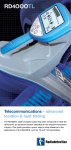
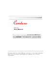
RD4000TL RECEIVER
RD4OOOTL
RD4000T10 TRANSMITTER
Primary Operations:
1 On/Off Key, Menu Select
Receiver on/off. Press and hold
for off. Secondary operation menu
= momentary press (see below).
2 Numeric Signal Display
Indicates signal response and
measurement units being used.
3 Frequency/Mode Indicator
Displays the selected frequency
or operating mode.
4 Left/Right Arrows
Indicates direction of target line
(automatic in Null mode).
5 Numeric Display
Displays the current gain value.
6 Power Mode
Power mode selected.
7 Radio Mode
Radio mode selected.
8 Line Selected Indicator
Line mode selected.
9 Sonde Indication
Sonde mode selected.
10 Bar Graph
Telecommunications - advanced
location & fault finding
The RD4000TL cable and pipe locator has been introduced to meet the
demand for an advanced locator dedicated to the telecommunications
industry. This guide provides a quick, step by step reference to the
applications of the RD4000TL and the T3 and T10 transmitters.
Displays signal strength (dB or %).
Peak is indicated by a lone bar
11 Fault Find (FF) mode
‘8k Fault Find’ via the A-Frame.
12 Antenna Display
Narrow Peak (twin horizontal
antenna), Null (vertical antenna).
13 Battery Level
Displays battery level. No locate is
possible at minimum (zero bars).
14 Depth or Current Display
Displays depth or current
as applicable.
15 Fault Find Arrows
Indicates the direction along the
pipe/utility to the measured fault.
www.radiodetection.com
RD4000T3(F) TRANSMITTER
Display Features
16 Antenna Select Key
Press and release selects Peak or
Null mode. Sustained press switches
between depth and current if available.
17 Gain Controls
Signal strength is indicated on bar
graph (50% is suitable). Unit
automatically servos to mid-scale gain
if signal outside useful operating zone.
Sustained hold of gain-up or gain-down
= steps of 1dB increment/decrement.
18 Function Key
Press and release to select the
required frequency/operating mode.
Secondary Operations:
Function Key & Gain Up/Down
Scrolls through operating modes
- press gain up and down & function key
together.
Function Key
Sustained Hold through power-on
sequence: Unit displays firmware revision
(DSP, FPGA), unit configuration number
and the date unit last calibrated.
Power On/Off Key Momentary Press
Set volume (4 levels) and battery type
(Alkaline, NiMH). Up & Down gain arrows
used to select options. Second press selects
the applicable menu.
Volume Control
Up & Down gain arrows scroll through
settings (VOL0, VOL1, VOL2, VOL3).
Momentary press of On/Off confirms
selection and exits menu.
Battery Selection
Operation identical to volume control.
Select type to match to battery level
indicator (alkaline or NiMH).
To Disable a Mode
Key menu select (1). Scroll to required
mode using arrow (17) and (1).
1 On/Off Key
Switches the transmitter on and off
and acts as the menu select key.
2 Measurement Indicator
Indicates which measurement is
being taken.
3 Induction Mode
Symbol displayed when induction
mode is selected.
4 Transmitter Indication
Symbol displayed the entire time
the transmitter is switched on.
5 Clamp Indicator Symbol
Displayed when a Signal Clamp
is connected.
6 Direct Connection
Indicator Symbol
Displayed when transmitter is
connected to line using direct
connection.
7 Text Display
Displays operating mode, frequency
submode and menus/alarms.
8 Numeric Frequency Display
Displays the output frequency and
measurement units being used.
9 Hi-Volts
Symbol displayed when 50V output
max is selected.
10 Volume Level
Displays volume level
(mute, low, medium, high).
Display Features
12 Battery Level
Displays transmitter battery level.
13 Bar-graph
Displays output current or power
setting demanded.
14 Numeric Measurement Display
Displays numeric measurement
information including the units
being used.
15 Up Key
Press to increase power output,
or to scroll up through menu
options and parameters. If power
output is increased to above
5 Watts, Hi-Power will scroll across
the screen, this will significantly
increase drain on the batteries.
16 Down key
Press to decrease power output
or to scroll down through menu
options and parameters.
17 Measurement Key
Press to select measurement units:
Amps/Volts in normal mode and
Volts/Ohms in measurement mode.
18 Live Cable Warning
Indicates when there is more than
30V on the output terminals.
1 On/Off Key
Switches the transmitter on and
off. The T3(F) will self-test for
2 secs, then switch to induction
mode, or direct connection mode
if connection leads are present.
2 Fault Find Indicator (FF)
LED indicates that FF mode
is selected.
3 Frequency Indicators
LED’s indicate the
selected frequency.
4 Power Output
LED’s indicate the selected
output level.
5 Induction indicator
LED indicates when induction
mode is selected.
6 Up Key
Press to increase power output.
7 Down Key
Press to reduce power output.
8 Frequency Key
Press repeatedly to scroll through
and select the required frequency.
Before doing this ensure that a
connection lead is fitted.
19 Frequency Key
Press and release to select the
required frequency. Holding
the key scrolls through the available
frequencies, release when the
required frequency is displayed.
11 External Power Supply Indicator
Symbol displayed when external
power supply is connected.
90/UG068ENG-01
LOCATING
LOCATING
How to use a stethoscope
Plug the stethoscope into the receiver accessory
socket. Select Stethoscope (Probe) using the
Function key (2); mode shows P and frequency
e.g. P640. Press the concave head against
each cable in turn to detect a maximum signal.
Passive Frequencies
These rely on signals already present on buried
metal utilities and do not require the use of a
Radiodetection transmitter. There are two types
of passive frequency.
Power
Power
Power cables and some other utilities radiate
a signal at 50/60Hz.
Types of stethoscope
Radio
In addition to power signals, some utilities
re-radiate ambient radio signals.
Radio
Active Frequencies
These require the use of a Radiodetection
transmitter to provide the locate signal, and give
very good depth and current readings. These
frequencies also travel greater distances and can
help to identify individual lines. Remember the
transmitter and receiver must be set to the same
frequency.
There are three methods of applying an active
signal using a Radiodetection transmitter.
Induction
Direct
Connection
Induction
The transmitter is placed over or near the area
to be located and switched to the appropriate
frequency. A signal will then be induced on to
any line(s) below or close to the transmitter.
Higher frequencies are normally used in this
method as they induce more effectively.
Direct Connection
Electrical connection leads are plugged into the
transmitter and attached directly to the line, the
circuit is completed by connection to a ground
stake (typically at 90° to the line). This method
ensures a strong clear signal on an individual line
and enables the use of lower frequencies, for
example current direction.
Signal Clamp
A Signal Clamp is plugged into the transmitter
and clamped around the line to couple the signal
to it. A range of Signal Clamps is available to
accommodate most conductors.
Stethoscopes
The RD4000TL supports the stethoscope antennas shown on the next page.
LOCATING
90mm
3.5in
FAULT FINDING
Depth and Current Measurement (CM)
Fault Find (FF)
• Depth and Current is displayed automatically where
applicable.
An A-Frame is used with RD4000 receiver and transmitter to locate cable
sheath-to-ground faults on power and telco lines. See below.
• It is important to position stationary over
located line.
1.Taking a reference reading
Note: The cm feature measures the actual current on
Small stethoscope antenna
The small stethoscope antenna has a 25mm/1in
concave head at the end of a 2m/78 inch lead.
The small stethoscope can be screwed into
an extension rod or used at the end of several
extension rods joined together for identifying
the line regardless of its depth. Therefore the receiver’s
strongest response may not come from the target line;
it may come from a shallow line to which the signal
has coupled.
Large stethoscope antenna
The large stethoscope antenna, which plugs
into the receiver accessory socket, is used for
cable identification in situations where the cable
is exposed. It is particularly useful for identifying
heavy cables lying in a tray where it is not possible
to fit a clamp. The concave detector head on the
end of the insulated, flexible gooseneck is placed
firmly against the cable to be identified. If there
are a number of cables, the stethoscope antenna
will give the strongest response from the cable to
which the transmitter signal has been applied.
A sonde is a small self contained transmitter that,
when inserted in a non-metallic drain, sewer, pipe
or duct, can be located by the receiver.
Locating a Sonde
• Select sonde (18).
• Select Peak mode (16).
• Hold the receiver vertically with the blade in line
with the sonde.
Peak
Ghost
Ghost
Peak Mode
• Move from side to side over the suspected
position of the sonde, to obtain a peak response.
Ghost peaks will be found on either side of a
main peak response.
• With the centre peak pinpointed move the
receiver back and forth across the line of the
sonde to obtain a second peak.
• Select Peak mode (16).
• Set the Gain (17) so that the bar graph is at
approximately 50%.
• Rotate the receiver to obtain a third peak
response. The receiver is now directly over
the sonde and a depth measurement will
automatically be displayed.
• Hold the receiver vertical and sweep the
area with a steady and deliberate motion. If
necessary adjust the gain to keep the bar graph
on scale.
• Current measurement is not applicable to sondes.
• When a signal is detected continue along the
search route until it reduces, then move back to
where the signal is strongest (Peak).
• Rotate the receiver until the signal is at its
weakest. The receiver handle will now be
aligned with the target line.
• Move the receiver from side to side using small
movements until a clear maximum is observed.
The receiver is now directly over the target line.
When to use a stethoscope
• Depth and Current, as selected, is
automatically displayed.
At times, it may not be possible to put a clamp around a cable because of
congestion or because of inaccessibility. A stethoscope antenna should be
used in the place of the clamp to identify cables.
• You can follow the line by moving forward while
at the same time moving the receiver from side
to side, observing the maximum response.
• Signal overload eg. Near a substation
transformer. Bar graph will flash. Depth and
Current not displayed.
Safety Information
The rechargeable battery packs can be recharged via a vehicle cigarette
lighter. Rechargeable battery packs must not be recharged whilst attached
to transmitter or locator units, if the vehicle is being driven.
Transmitter variants can by powered via the vehicle cigarette lighter of a
stationary vehicle. The RD4000 is designed for use by suitably trained
personnel, following procedures and instructions described in the full user
manual. For comprehensive approval, warning and safety information, refer to
the full RD4000 user manual.
• Pinpoint the line and trace its route for a short distance.
• Connect the A-frame to the receiver. Select 8KFF (18)
FF mode selected and A-frame symbol displayed.
• Select FF mode on the transmitter and ensure
the ground stake is connected.
Red
Green
Line fa
ult
ahead
RD4000T10
• Press on/off (1) to select the menu and scroll
using the down arrow (3) to select FF.
• Press on/off (1) again to confirm the selection.
RD4000T3F
• Press the frequency key (8) until the FF LED is lit.
• Place the A-frame spikes in the ground approx. 2 meters from
the ground stake and with the green spike facing it.
• Ensure the receiver is in line with the A-frame and facing the green
spike. The FF arrows should point away from the ground stake.
• Make note of the dB reading. During fault find, if the dB reading is approx.
equal to the reference there is a single fault. If the dB reading is less than
the reference there are multiple faults, in this case the sum of all
dB readings should be approx. equal to the reference.
2. Fault Finding
• Place the A-frame spikes in the ground with the red spike nearest
the ground stake.
• The FF arrows will display the fault direction. The arrows should point
away from the ground stake and the bar graph should read zero.
• Follow the cable pushing the A-Frame spikes into the ground at
regular intervals and checking for FF arrows. With no fault, the arrows
will flicker on and off and the dB readings will be erratic.
• Keep the red spike facing the ground stake and keep the receiver
in line with the A-Frame. Near a fault, the arrows will lock on and the
dB reading will increase.
• Move in the direction of the arrows. Find the point at which the
arrows change direction.
• Rotate through 90° and move back and forth to locate the fault in
this direction, the intersection point will be directly over the fault.
• Should the location of the cable become uncertain the mode select key (18)
can be used to change between locate mode and FF mode.
VΩ readings (RD4000T10 only)
This function can be used to confirm the presence of a fault.
Note: All earth bonds MUST be removed from the cable.
• Press on/off (1) to select the menu and scroll using the down arrow (16)
to select Measure.
• Press on/off (1) again to confirm the selection
• Press the measurement key (17) to select ohms and take a resistance
reading. A low resistance (typically less than 2MΩ) indicates a fault.
Line fa
ult
behind