1
KIT-NB85E-TP
User's Manual
RealTimeEvaluator
KIT-NB85E-TP
User’ s Manual
Revision History
Rev.0.8
Jul. 24, 1999
Preliminary 1st edition
Rev.1.0
Sep. 24, 1999
Official 1st edition
The initial value of JTAG CLK changed
to 12.5 MHz
1
KIT-NB85E-TP
User’ s Manual
CONTENTS
1. OVERVIEW....................................................................................................................................... 3
2. HARDWARE SPECIFICATIONS ....................................................................................................... 4
Emulation........................................................................................................................................... 4
Host system and interface .................................................................................................................. 5
3. RTE FOR WIN32............................................................................................................................... 6
Starting ChkRTE32.exe ...................................................................................................................... 6
4. INITIALIZATION COMMANDS.......................................................................................................... 7
env command..................................................................................................................................... 7
rom command .................................................................................................................................... 8
5. INTERFACE SPECIFICATIONS ........................................................................................................ 9
Pin arrangement table ........................................................................................................................ 9
Connectors......................................................................................................................................... 9
Wire length......................................................................................................................................... 9
Layout of the connectors on the board .............................................................................................. 10
6. PRECAUTIONS .............................................................................................................................. 11
Precautions related to operation ....................................................................................................... 11
Precautions related to functions ........................................................................................................ 11
2
KIT-NB85E-TP
User’ s Manual
1. OVERVIEW
KIT-NB85E-TP is a product to use RTE-100-TP. It is an in-circuit emulator for NEC's RISC processor,
NB85E (ASIC-Core) by using KIT-NB85E-TP and RTE-100-TP together.
Please read a User's Manual of RTE-100-TP together.
This product comes with the following components. First check that none of the components are
missing.
• RTE for Win32 Setup Disk
• User's manual (This manual)
• License sheet
3
KIT-NB85E-TP
User’ s Manual
2. HARDWARE SPECIFICATIONS
Emulation
Target device
ASIC microcontroller using NB85E as core
RTE-TP
RTE-100-TP
Emulation functions
Operating frequency
66 MHz (max.)
Interface
JTAG/N-Wire
Event function
Number of events
Setting of execution address
Setting of data access
12
6
Address specification
Maskable
Data specification
Maskable
Status specification
Maskable
Number of sequential unit stages
4
Break functions
H/W break points
2
S/W break points
100
Breaks that can be set using events
Supported
Step breaks
Supported
Manual breaks
Supported
Trace functions
Trace data bus
4 bits
Trace memory
4 bits x 128K words
Trigger setting
Supported
Trigger that can be set using an execution
address
Supported
Trigger setting by event
Supported
Trigger setting by external input
Supported
Start/stop by execution address
Supported
Trace delay
0 - 1FFFFh
Trace clock
66 MHz (max.)
Disassembled trace data display function
Complete trace mode specification function
Provided
Provided (no real time)
ROM emulation functions
Memory capacity
Access time
4 M-Byte
50 ns
Number of ROMs that can be emulated
DIP-32pin-ROM (8-bit ROM)
4 (max.)
DIP-40/42pin-ROM (16-bit ROM)
2 (max.)
STD-16BIT-ROM connector
2 (max.)
Types of ROMs that can be emulated
DIP-32-ROM probe (bits)
1M, 2M, 4M, 8M (27C010/020/040/080)
DIP-40-ROM probe (bits)
1M, 2M, 4M (27C1024/2048/4096)
DIP-42-ROM probe (bits)
8M, 16M (27C8000/16000)
Bus width specification (bits)
Target ROM capacity (bits)
Pin mask functions
8/16/32
1M, 2M, 4M, 8M, 16M(*1)
RESET, STOP, NMIx, VAREQ, WAIT-, INTxx
*1 An 8-bit ROM probe supports ROMs of up to 8M bits.
4
KIT-NB85E-TP
User’ s Manual
Host system and interface
Item
Description
Target host machine
PC 9800 Series and DOS/V PCs
Debugger
Partner/Win (Windows95/98/NT)
Interface
PC card Type II (version 2.1 of the PCMCIA specifications/version 4.2 of the JEIDA
specification or later)
PC 9800 (C bus), PC/AT (ISA bus and PCI bus), or LAN-BOX
Power supply
AC adapter (in: 100 V out: +5 V, 2A)
5
KIT-NB85E-TP
User’ s Manual
3. RTE FOR WIN32
This chapter describes the setting of RTE for WIN32, with the focus on the aspects specific to KITNB85E-TP.
Starting ChkRTE32.exe
Start ChkRTE32.exe after RTE-100-TP has been connected to the user system and the power to all the
devices is on. When RTE-100-TP is installed for the first time, ChkRTE32.exe must be started once to
select RTE.
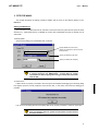
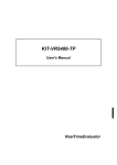
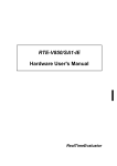
<Selecting RTE>
Set the Setup dialog box of ChkRTE32.exe, as follows.
Specify NB85E-TP (xxxxx,xxxxx).
(Specify the mode of the CPU to be used
NB85E-TP(xxxxx,xxxx)
as xxxxx,xxxxx.)
Specify the interface to be used.
Specify an address as necessary.
The NB85E-TP (xxxx,xxx) specified by RTE: is intended for use with
a system employing the NB85E-TEG. Consult NEC for further
information on how to specify when using a custom microcontroller
with the ICE.
<Function test>
If RTE-100-TP is properly connected to the user system and capable of debugging, the following dialog
box appears upon the normal completion of the function test. In this state, control from the debugger is
possible.
If an error occurs during the test, the N-Wire cable is not properly connected. Check its connection.
Perform the ChkRTE32.exe function test after the RTE-100-TP has
been connected to the user system and the power to all the devices
has been turned on.
6
KIT-NB85E-TP
User’ s Manual
4. INITIALIZATION COMMANDS
Before debugging can be started, initialization is required. The following explains initialization using the
appropriate internal commands. If the debugger offers a means of initialization, they may be used instead.
(See Appendix A for an explanation of starting the internal commands and an explanation of the other
internal commands.)
env command
[Format]
env
[[!]auto] [[!][verify]] [[!]reset] [[!]stopz] [[!]hldrq] [[!]nmi0]
[[!]nmi1] [[!]nmi2] [jtag{25|12}] [rtrcb{0|25|50|75}]
[nrtrcb{12|25|37|50}] [64m|256m]
[romless|single0|single1] [d0|d1|d2|dauto] [i0|i1|i2|iauto]
[Parameters]
[!]auto: If a break point is encountered during execution, the break point causes a temporary break.
Choose [Auto] to automatically perform the subsequent execution. Choose [!auto] to
suppress it.
[!]verify: Specifies the verification after writing memory is set. Enter ! if it is not to be set.
Remark The CPU also accesses an area that emulates ROM (jread or equivalent).
Therefore, this command is useful for testing the area during downloading.
Note, however, that the processing speed slows down.
[!]reset:
Specifies whether the RESET pin is to be masked. Enter ! if it is not to be masked.
[!]stopz:
Specifies whether the stopz pin is to be masked. Enter ! if it is not to be masked.
[!]hldrq:
Specifies whether the hldrq pin is to be masked. Enter ! if it is not to be masked.
[!]nmi{00|01|02}: Specifies that pins INT00 to INT03 are to be masked. Enter ! if they are not to be
masked.
jtag[12|25]:
Specifies the JTAG clock (12.5 MHz|25 MHz) for N-Wire.
rtrcb {0|25|50|75}:
Specifies the occupied capacity of the buffer when execution returns from
overflow during real-time trace.
Ordinarilly, use the initial value of this
parameter.
nrtrcb {12|25|37|50}: Specifies the occupied capacity of the buffer when a request to stop the
pipeline is made in complete trace mode. Ordinarilly, use the initial value of
this parameter.
64m|256m: Specifies an address mode of the CPU.
64m:
Specifies the 64M mode.
256m:
Specifies the 256M mode.
romless|single0|single1: Specifies an operation mode of the CPU.
single0m: Specifies the single mode 0 (internal ROM from address 0).
single1:
Specifies the single mode 1 (internal ROM from address 100000h).
Romless: Specifies the ROM-less mode.
7
KIT-NB85E-TP
User’ s Manual
[rd0|d1|d2|dauto]: Specifies data cache.
d0:
Specifies no data cache.
d1:
Specifies the cache of direct map.
d2:
Specifies the 2-WAY cache.
dauto:
Specified in the case of NB85E-TEG for automatic setting.
[i0|i1|i2|iauto]:
Specifies instruction cache.
i0:
Specifies no instruction cache.
i1:
Specifies the cache of direct map.
i2:
Specifies the 2-WAY cache.
iauto:
Specified in the case of NB85E-TEG for automatic setting.
[Function]
The env command displays the correspondence between the emulation environment settings
and the DCU.
rom command
[Format]
rom [ADDR [LENGTH]] [512k|1m|2m|4m|8m|16m] [rom8|rom16] [bus8|bus16|bus32]
[Parameters]
ADDR
[LENGTH]:
ADDR:
Specifies an area to be emulated.
Specifies a start address. An error occurs if the specified start address
does not match the lowest address of the ROM to be emulated
(boundary of the ROM).
LENGTH:
Number of bytes of the ROM to be emulated. (Must be specified in
boundary units of 4 bytes.)
512k|1m|2m|4m|8m|16m:
Specifies the bit size of the ROM to be emulated.
Sizes from 512K bits to 16M bits can be specified. For the 27C1024, for
example, specify 1M bits.
rom8|rom16:
Specifies the number of data bits of the ROM to be emulated.
Either 8 bits or 16 bits can be specified. If a DIP-32-ROM probe is used,
choose rom8; if a DIP-40/42-ROM probe is used, choose rom16.
bus8|bus16|bus32:
Specifies the ROM bus size in the system to be emulated. 8 bits, 16
bits, or 32 bits can be specified.
[Function]
The rom command sets the ROM emulation environment. Enter only the parameters that need to be
changed. Parameters may be entered in any order. If the same parameter is entered twice, only the
last entry is valid. The initial value of LENGTH is 0 (not used).
8
KIT-NB85E-TP
User’ s Manual
5. INTERFACE SPECIFICATIONS
This chapter describes the specifications of the connectors used for control that are required for the user
system.
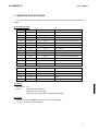
Pin arrangement table
Pin number
Signal name
Input/output (user side)
Treatment (user side)
A1
CLKOUT
Output
22 - 33 Ω series resistor (recommended)
A2
TRCDATA0
Output
22 - 33 Ω series resistor (recommended)
A3
TRCDATA1
Output
22 - 33 Ω series resistor (recommended)
A4
TRCDATA2
Output
22 - 33 Ω series resistor (recommended)
A5
TRCDATA3
Output
22 - 33 Ω series resistor (recommended)
A6
TRCEND
Output
22 - 33 Ω series resistor (recommended)
A7
DDI
Input
10 kΩ pullup
A8
DCK
Input
10 kΩ pullup
A9
DMS
Input
10 kΩ pullup
A10
DDO
Output
A11
DRST-
Input
10 kΩ pulldown
A12
NC.
------
Open
A13
NC.
------
Open
Pin number
Signal name
Input/output (user side)
B1-B10
GND
------
Connection to the power GND
B11
NC.
------
Open
B12
NC.
------
Open
B13
+3.3V
------
Connection to the power
22 - 33 Ω series resistor (recommended)
Treatment (user side)
Connectors
Manufacturer: KEL
Models:
8830E-026-170S (straight)
8830E-026-170L (right angle)
8831E-026-170L (right angle, fixing hardware attached)
Wire length
Keep the wire from the NB85E to the connector as short as possible.
>>100 mm or shorter is recommended.
9
KIT-NB85E-TP
User’ s Manual
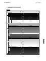
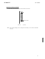
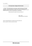
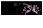
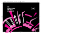
Layout of the connectors on the board
The figure below shows the physical layout of the connectors on the board.
B13 A13
B12 A12
Polarity indication
B2 A2
B1 A1
Board end
Note
[Top View]
When actually arranging the pins, design them according to the connector dimensional
information.
10
KIT-NB85E-TP
User’ s Manual
6. PRECAUTIONS
This chapter provides precautionary information on the use of KIT-NB85E-TP.
Precautions related to operation
1) Do not turn on the power to the user system while the power to KIT-NB85E-TP is off. Doing so can
cause a malfunction.
2) KIT-NB85E-TP externally controls the debugging control circuit built into the NB85E. Consequently,
KIT-NB85E-TP does not operate correctly unless the following conditions are satisfied:
* KIT-NB85E-TP is properly connected to the user system using the N-Wire cable.
* The power to the user system is on so that the NB85E can run correctly.
Precautions related to functions
1) The disassembly and display of real-time trace data is performed by reading the contents of memory
at the point the trace display command is issued, according to the branching information received
from the NB85E. Consequently, the disassembly and display of the program located in RAM of the
user system is not correct if changes (including erroneous writing due to a CPU hang up) are made
after program execution. Note that the following functional constraints must be observed.
2) If the trace information is limited by using the tron command, trace display may not be correctly
performed. Therefore, specify all ON (start) or all OFF (stop) under normal conditions.
3) Step execution of the ROM space cannot be performed with a CPU that does not have a TEU (event
trigger unit). An error occurs if an attempt is made to perform step execution.
4) A breakpoint in the ROM space is invalid if the breakpoint is set to the second instruction of an
instruction string that simultaneously execute two instructions.
5) For further information, be sure to refer to the Release Note of the KIT.
11