1
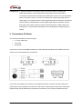
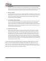
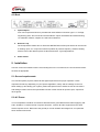
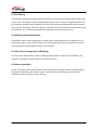
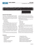
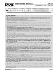
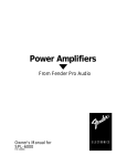
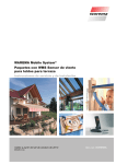
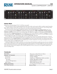
Manual
Compressor DualCom 52
Table of contents
1.
Safety instructions ............................................................................................................................ 3
1.1.
2.
FOR SAFE AND EFFICIENT OPERATION ............................................................................ 3
Introduction ....................................................................................................................................... 4
2.1.
What compressors and limiters do .......................................................................................... 4
3.
Connectors & Cables ....................................................................................................................... 5
4.
Control / Connections ....................................................................................................................... 6
5.
6.
4.1.
Front ........................................................................................................................................ 6
4.2.
Back ......................................................................................................................................... 8
Installation ........................................................................................................................................ 8
5.1.
General requirements .............................................................................................................. 8
5.2.
AC Power................................................................................................................................. 8
Typical applications .......................................................................................................................... 9
6.1.
The unit as a protective device ................................................................................................ 9
6.2.
Recording ................................................................................................................................ 9
6.3.
De-Essing .............................................................................................................................. 10
6.4.
Altering instrument texture..................................................................................................... 10
6.5.
Voice-Over Compression (Ducking) ...................................................................................... 10
6.6.
Stereo operation .................................................................................................................... 10
7.
Troubleshooting.............................................................................................................................. 11
8.
Dimensions ..................................................................................................................................... 12
9.
Specifications ................................................................................................................................. 12
2 / 13
1. Safety instructions
•
Read the safety instructions and also this manual carefully.
•
Keep the manual.
•
Observe all red flags.
•
Observe the manual.
•
To prevent fire or electric shocks, protect the device against rain and
humidity
•
Pull the plug before opening the housing.
•
To prevent an electric shock you should not remove the cover.
•
Do not operate the device in the near of water.
•
Use only a dry cloth for cleaning.
1.1. FOR SAFE AND EFFICIENT OPERATION
Be careful with heat and extreme temperature
Avoid exposing it to direct rays of the sun or near a heating appliance.
Not put it in a temperature bellow 32°F /0°C, or exceeding 104°F /35°C.
To avoid placing on un-stable location
Select a level and stable location to avoid vibration.
Do not use chemicals or volatile liquids for cleaning
Use a clean dry cloth to wipe off the dust, or a wet soft cloth for stubborn dirt. Pull the plug before
cleaning.
If out of work, contact sales agency immediately
Any troubles arose, remove the power plug soon, and contact with an engineer for repairing, do not
open the cabinet by yourself, it might result a danger of electric shock.
Take care with the power cable
Never pull the power cable to remove the plug from the receptacle, be sure to hold the plug. When not
using the device for an extended period of time, be sure to disconnect the plug from the receptacle.
Ventilation
It is not allowed cover fans and air in and outlets.
3 / 13
Safety
Do not remove the grounding. It is for your safety. If you remove the grounding it can cause electric
shocks.
Hearing
To avoid hearing damages, you should not operate a sound system with high levels. This applies to
monitor systems, which are in the near of the ear, headphones or IEMs also.
Accessory
Please use only the accessory which is set by the manufacturer.
Important
Damages caused by the disregard of this user manual are not subject to warranty. The dealer will not
accept liability for any resulting defects or problems. Make sure the electrical connection is carried out
by qualified personnel. All electrical and mechanical connections have to be carried out according to
the European safety standards.
2. Introduction
Congratulations on your purchase of the compressor/Limiter. Te unit was designed to meet the need
for universal peak-sensitive automatic gain control (AGC) devices with exceptional audio performance
and rugged durability. The unit has the following key features.
•
Treshold control
•
Input/output meter with select switch
•
Balanced XLR connectors
•
A single TRS patch point detector loop
•
Premium components throughout
•
Quality construction through computerized, automated assembly
We are confident that you will be pleased with the high performance, superb sound quality, and
reliability that we are known for.
2.1. What compressors and limiters do
Limiting
All musical programs have constant changes in loudness. It is the job of a limiter to
detect when the volume has exceeded a predetermined maximum safe level, and to
turn down the volume. When the incoming signal returns to its original level, the limiter
should respond by restoring the gain to normal. Thus, when the level is within a
specified ‘safe’ range, the limiter has no effect. When an occasional peak occurs, the
limiter responds.
4 / 13
Compressing A significant difference in dynamic range is achieved simply by changing the
relationship between nominal signal level and threshold, as a result of either
increasing the GAIN and/or decreasing the TRESHOLD control. The most interesting
effect to be noted, however, is seen by comparing the original input signal with the
output signal. The quietest portions of the original signal will be effectively increased in
volume while the loudest portions of the original signal will be decreased. In effect,
both ends of the dynamic spectrum will be pushed toward the ‘middle’. More than
anything else, it is this double-ended effect, which distinguishes compressing from
limiting.
3. Connectors & Cables
The unit has three different connector types:
•
¼‘‘ stereo TRS jacks
•
3-Pin XLR
•
Euroblocks
These three connectors facilitate interfacing to most professional audio products. Both inputs and
outputs can be used balanced or unbalanced.
If you must use unbalanced connectors, the negative lead of the connector should be tied to the
ground lead. Using unbalanced connections could result in chassis ground-loop noise. Altering the
signal/chassis ground relationship in equipment connected to your unit may eliminate the noise.
5 / 13
4. Control / Connections
4.1. Front
1. Gain
The Gain control adjusts incoming signal level to the VCA circuit. It is always active, so
switching out the limiter function has no effect on this control. This control should normally be
left at ‘0’ to achieve accurate threshold calibration.
2. Treshold
The threshold control has a range of -40 to +22dB, allowing applications from low level
compression to high level limiting. The threshold control determines the audio level above
which gain reduction occurs. When the signal peaks exceed the selected threshold, the LED
comes on and gain reduction is occurring,
3. Ratio
This control determines the ratio of the change in output level to changes in input level for
signals above threshold. The numbers printed around the ration control are calibrated in dB
and indicate the increase input (above threshold) required to produce a 1dB increase in
output. This can be expressed conveniently as a ratio. If the output remains constant no
matter how high the input level, we have an infinite (∞) input/output ratio. It should be
remembered that the ratio control has no effect on signals which are below threshold.
4. Attack Time
The response of the compressor/limiter to signal levels above threshold is further defined by
the attack time control. Attack time is the amount of time that the unit takes to attenuate the
output level after threshold has been reached. This unit provides continuously variable attack
times from 200 µs und 20 ms.
5. Release Time
Release time, is the time required to restore system gain to normal after the input signal has
fallen below threshold level. Proper release time will depend on the type of program material
being processed and the way in which the limiter is being used.
6. Output Level
Output level control is provided to fully cut or restore up to 18dB of system gain. For unity
gain, set the control to 0.
6 / 13
7. In/Out Switch
This switch enables you to quickly hear the compressor/limiter in or out of the audio chain.
When the switch is in the OUT position, all limiting and compression controls and functions are
bypassed, with the exception of the gain and output controls, which continue to function.
8. Stereo Tie Switch
This switch allows for gain reduction on a stereo signal with no degradation of a stereo image.
When pressed in, the stereo tie switch combines each channel’s internal detector outputs so
that the channel with the loudest signal will determine the action applied to both channels.
Leave this switch for normal operation.
9. Treshold/Gain reduction display
As soon as the threshold level is reached, the yellow LED illuminates. Depending on how far
the input level rises above threshold, successive red LEDs will illuminate, indicating gain
reduction. Gain reduction can best be described as the difference between input level and the
resulting change to output level. For signals above threshold, output level will increase only to
the extent that the ratio control allows.
10. Input/output meter select
While the gain reduction display accurately represents the action of the limiter, comparing
input to output level in real time is somewhat more intuitive, and is made simple using the
input/output meter select switch. The input meter takes its signal just after the gain control,
and will indicate input signal level regardless of output levels or limiter settings. The output
meter display takes its signal from the actual output of the unit, so every control that affects
the output will also have an effect on output meters. Use in conjunction with the gain reduction
meters. Input/output meters prove to be an extremely useful diagnostic tool when working with
system dynamics and level control.
A unique feature of this compressor/limiter is the incorporation of a double release-time constant.
When a conventional compressor/limiter is adjusted for slow release times, transient such as mic
‘pops’ may cause a severe reduction in gain followed by a slow fade up, making the action of the
limiter very obvious. With the double fine constant, release from gain reduction after a brief transient is
always fast, with a slower release after a sustained overdrive.
7 / 13
4.2. Back
1. Inputs/outputs
Your unit Compressor/Limiter is provided with three different connector types: ¼’’ TRS (tipring-sleeve) jacks, XLR connectors and Euroblocks. Inputs are 20kΩ active balanced using
1% metal film resistors, outputs are 132Ω servo-balanced.
2. Detector Loop
The Compressor/Limiters have a TRS insert DETECTOR PATCH point which can be used as
a ‘ducking’ input, or in conjunction with an equalizer to produce frequency-sensitive limiting.
Various uses of the detector patch are discussed under ‘Typical applications’.
3. Power switch
5. Installation
Use four screws and washers when rack mounting the unit. For mobile use, the unit should be further
secured as appropriate.
5.1. General requirements
The unit has specific physical, electrical and signal requirements for proper operation. These
requirements will vary depending on your specific application, setup, and the settings on the unit.
When setting up and testing your system, please take special care to double check all connections
and settings. Please refer to the specifications section of this manual for specific input, output and
other figures.
5.2. AC Power
Your unit equalizer should be connected to standard 3-wire grounded electrical outlet supplying 100240V, 50-60Hz. To reduce the risk of ground loop hum, connect all audio equipment to the same
electrical power source. Removal of the ground pin is both unlawful and dangerous, as a potential
shock hazard could result.
8 / 13
6. Typical applications
The application of this unit can be divided into two basic categories, limiting and compressing.
When used as a protective device it is functioning as a limiter. It may also be used to reduce the
dynamic range of a signal, creating a fuller sounding signal without increasing the loudest peaks, in
which case it is functioning as a compressor.
6.1. The unit as a protective device
The unit provides fast an accurate gain control for the prevention of sound system overload due to
unexpected transients. Sustained distortion caused by amplifiers running out of power or occasional,
one-shot high level overload (a microphone falling onto a hardwood floor) can damage speakers and
other system components. The unit can be installed in several locations in a sound system to specific
goals:
Signal path location
Effect
After the mixer and before the crossover and
Compression and limiting acts on the entire
amplifier(s)
signal, preventing crossover and amplifier
overload and maximizing the dynamic
performance of both.
After an active crossover and before the
Compression and limiting acts on each segment
amplifier(s)
of the signal (to which a unit channel is
connected) coming from the crossover allowing
for different setting in each segment.
After a parametric EQ and before the amplifier(s)
This setup is typically used to control feedback.
By using the parametric EQ as a multipoint
notch-filter on the feedback frequencies and the
unit to limit those frequencies, an accurate and
automatic feedback control can be imposed on a
system.
6.2. Recording
The unit limiter can be used to prevent input overload (clipping/distortion) in a live recording
environment. To prevent distortion while preserving dynamic range set the unit as follows: Gain=0,
Threshold=2-3dB below recorder input max, Ratio=10, Attack=2ms, Release=2s, Output=0. Every
situation is different, so experimentation before final recording is always a good idea.
9 / 13
6.3. De-Essing
A special type of saturation problem often encountered in recording is the sibilant (Ssss) sound of the
human voice. The solution is frequency-dependent limiting, which is easily accomplished with the unit.
By inserting an equalizer into the detector patch point and boosting the equalizer at high frequencies
in the vicinity if the sibilant, the limiter’s detector circuit becomes more sensitive to this particular range
of frequencies, and so will limit the bothersome sibilants more than other frequencies.
6.4. Altering instrument texture
Compression can be used to help bring out a lead vocal or instrumental solo in a cluttered mix. The
compressor is also a great corrective tool when working with singers whose own dynamic control is
less than perfect. Experimentation is highly recommended.
6.5. Voice-Over Compression (Ducking)
The unit can be used to reduce music to a background level when an announcer is speaking. The
detector is connected to respond only to an announcer’s voice.
6.6. Stereo operation
On the unit, pressing the stereo tie switch combines the detector outputs so that the loudest channel
controls the limiter action of the other channel. This allows true stereo imaging to be preserved
regardless of which channel is in gain reduction.
10 / 13
7. Troubleshooting
Situation
Action
No audio output
Check AC power- Is the power switch on? Check
input and output connections-are they reserved?
Are you sure you have an input signal?
Controls have no effect
Is the Limiter in/out switch in? Perhaps the ratio
control is set too low to produce an audible effect
or the input level is below threshold. Is the
threshold LED lighting up? If not, lower the
threshold setting or increase the gain. Do not
expect to hear any affect when the input level is
below threshold, since the unit is simply a linear
amplifier at those levels.
When using heavy compression, background
Quiet program material is effectively made louder
noise is noticeable during quiet section of the
while loud peaks are made quieter. When the
program
program source is thus raised in volume, its
noise floor is also raised in volume by a
propionate amount. This is not a defect in the
compressor/limiter, but an unavoidable side
effect of the gain altering process. If the noise
becomes a problem, the solutions are to either
decrease noise at the program source, or use
less compression.
Excessive hum or noise
Hum is often caused by a ‘ground loop’ between
components. Try using the suggested balanced
input and output hookup if the other pieces of
equipment used in conjunction with the unit have
balanced inputs and outputs. Make sure you are
sending a nominal 0dBV line level signal to the
unit.
Unshielded cables, improperly wired connections, and cable with broken strands (shorts, etc.) are the
most common problems. Make sure you use good quality cable with connectors soldered firmly on the
correct pin. When in doubt, get in touch with your dealer.
11 / 13
8. Dimensions
In inches:
9. Specifications
Gain
+/- 5dB
Ratio
2:1
Attack time
200s-20ms
Release time
100ms-3s
Output
-∞ to +18dB
Maximum input level
+23dB
Maximum output level
+23dB
Input impedance
20kΩ balanced
Output impedance
132Ω servo-balanced
Frequency response
20Hz-20kHz, +/- 0.2dB
Distortion
∞
<0.1% THD, 0dBu, 1kHz
<0.15% THD, + 15dBu, 20Hz-20kHz
Output hum and noise
-96dB
Power Requirements
100-240V, 50-60Hz, 30W
Measurements
580x4.44x20.3cm
Weight
3.6kg
Note: 0dBu=0.775Vms
12 / 13
Importer:
B & K Braun GmbH
Industriestraße 2
D-76307 Karlsbad
www.bkbraun.com
[email protected]
13 / 13