1
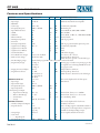
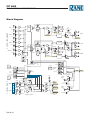
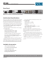
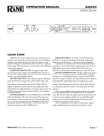
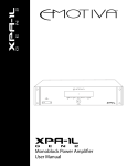
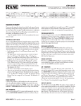
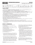
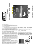
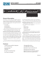
DATA SHEET
CP 64S
COMMERCIAL PROCESSOR
PAGING
ZONE ASSIGN
PAGE 1
PAGE 2
PROGRAM INPUT LEVELS
LEVEL
ZONE 1
ZONE 2
1 2
1 2
RMT
1&2 RMT
1&2
4
6
0
10
2
ACTIVE
8
4
6
0
10
2
LINE 1
8
4
6
0
10
2
LINE 2
8
4
6
0
10
2
LINE 3
8
4
6
0
10
2
ZONE 1
PRIORITY
8
4
6
0
10
2
8
DUCKER PROGRAM
DEPTH
SELECT
L2 L3
L1
P
RMT
OFF
ON
ACTIVE
ZONE 2
LEVEL
4
6
2
8
0
10
DUCKER PROGRAM
DEPTH
SELECT
L2 L3
L1
P
RMT
OFF
ON
ZONE 1
4
12
•
•
COMMERCIAL
PROCESSOR
0
•
8
SIG OL
CP 64S
6
6
2
0
SIG OL
ZONE 2
+
LEVEL
6
•
10
12
40
100
250
630
1.6k
4k
10k
40
100
250
630
1.6k
4k
10k
POWER
Optional SCP 2S Equalizer-only Security Cover
General Description
The CP 64S is a versatile commercial preamplifier designed for
use in restaurants, bars, health clubs and offices. The CP 64S is
capable of serving two independent Zones. Two gated Paging
inputs and four Program inputs are provided. Ports are provided
for expansion of Page, Program or Zone signals. Four levels of
priority are supported:
• Priority Page
• Non-Priority Page
• Priority Program
• Non-Priority Program
The versatility of the CP 64S allows a wide variety of system
configurations while providing simple and intuitive controls.
Two gated Paging Inputs capable of receiving mic or line
level input are provided. Each features independent Mic/Line
Pad, Gain Trim, detector Threshold, Zone Assign and Zone
Level controls. Internally selectable phantom power is provided
for each input. Each Paging input may be summed Pre- or PostZone Level control to allow setting Paging Level independent of
Zone Level. An internal Paging Priority switch allows a “master”
pager to override non-priority paging in its assigned zones, while
allowing true dual zone independent paging. If no Paging Priority is selected, the Paging inputs mix together for applications
like karaoke.
Four stereo Program inputs are provided with independent
Input Level controls. Any one of the four Program inputs may
be independently assigned in each Zone. One of the Program
inputs is a gated Priority Program input. When signal is detected
at its input, it overrides any non-priority Program selection in the
assigned Zones. The Priority detector features internal, adjustable
Threshold and Release-Time controls.
The CP 64S has two Zone outputs: Zone 1 is stereo: Zone 2
is mono. Each Zone features independent:
• Level
• Program Select
• Ducker On/Off
• Ducker Depth
• Servo-Locked-Limiter™
• 7 Band EQ (±12 dB)
Versatile wired remote control interface ports are provided
for Paging assignment, Zone Level and Zone Program source
selection. Paging Zone and Source/Volume remote controls are
available as accessories.
Many options allow the installer to determine exactly which
controls are employee accessible. The SCP 2S is an optional security cover for the CP 64S’s front panel EQ section. Any or all
other front panel knobs can be removed and replaced with hole
plugs — six are included with the SCP 2S. Front panel Ducker
Depth controls are screw driver adjust. The remote controls allow
blank Decora™ plates to be remote control security covers. The
remote knobs can also be individually replaced with hole plugs.
Features
•
•
•
•
•
•
Two fully independent gated Mic/Line Paging Inputs
Three stereo Program Inputs
Paging Priority Assign
Page Ducking
One gated stereo Priority Program Input
Page / Program / Zone Expansion
•
•
•
•
•
•
7-Band graphic EQ for each Zone
Servo-Locked-Limiter™ for each Zone
Optional SCP 2S Security Cover for EQ section only
Optional PR 2 Remote Page Assign Remote
Optional ZR 1 Remote Zone Level/Program Select Remote
NEW! Universal Internal Power Supply (100-240 VAC)
Data Sheet-1
CP 64S
COMMERCIAL PROCESSOR
Features and Specifications
Parameter
MIC/LINE PAGING INPUTS
..........Input Type
..........RFI Filter
..........Gain range
..........Frequency Response
..........Input Referred Noise
..........CMR
..........THD+N
..........Phantom Power
..........Mic Input impedance
..........Line Pad
..........Line Input impedance
..........Signal Detector Range
..........Signal Detector Attack
..........Signal Detector Release
..........Overload Indicator
..........Front Panel Zone Assign
..........Remote Zone Assign
..........Pre/Post Paging assign
..........Page Priority Assign
..........Paging Zone Level Adjust
..........Page Remote Selector
PROGRAM INPUTS
..........Input Type
..........Input Level adjust
..........Frequency Response
..........Input impedance
.....Priority Program Input
...............Input Detector Range
...............Release Time Range
...............Attack Time
...............Assign
EXPAND OUTPUTS
..........Number of Expand Outputs
..........Expand Selector
..........Output Type
..........Gain: Zone
....................Page/Program
..........Frequency Response
Data Sheet-2
Specification
Two mono
Euroblock
Yes
+30 to +60
30 Hz to 40 kHz
-125
40
.05
+15
500
30
14.5k
off to +4
.5
3
+16
Remote, Z1, Z2, Both
Off, Z1, Z2, Both
Limit
Units
Conditions/Comments
All controls duplicated for both inputs
Balanced; Instrumentation amplifier
2
+0/-3
1
min
.01
4%
1%
1
1%
typ
typ
typ
1
dB
dB
dBu
dB
%
VDC
Ω
dB
Ω
dBu
msec
sec
dBu
Continuously adjustable
Maximum gain
Gain: 60 dB, Rs: 150 Ω, BW: 20 kHz
20 to 20 kHz
Gain: 30 dB, +4 dBu out, 1 kHz, BW: 80 kHz
Internal switch
Each leg to ground
off to -35
5 to 20
50
OFF, Z1, Z2 or Both
typ
typ
typ
dBu
sec
msec
Internal trim, factory set to -50 dBu
Internal trim, factory set to 12 seconds
For a 20 dB step; Fixed.
Each leg to ground. Defeats phantom power
Continuously adjustable
Fixed
Fixed
4 dB before clipping.
Z1 = Zone 1; Z2 = Zone 2
Internal pull-up; Active low;
Switch closure to ground or 5 volt TTL logic.
Summed with program Pre VCA or Post VCA via Internal switch
P1 (Page 1)
1
dBu
Priority pager overrides non-priority pager only
NO (none)
in assigned zones; Selecting NONE allows the
P2 (Page 2)
two pagers to mix.
off to 0
dB
Independent for each Zone
11 = Off
1
dBu
Internal pull-up. Active low;
10 = Z1 (Zone 1)
Switch closure to Ground or 5 volt TTL logic.
01 = Z2 (Zone 2)
00 = Both
Four stereo
All controls duplicated for all four inputs
RCA
Unbalanced
off to 0
dB
10 Hz to 50 kHz
+0/-3
dB
10 k
20%
Ω
Two
Zone
Program only
Page only
Balanced
12
6
10 Hz to 50 kHz
All controls duplicated for both zones
Z1 & Z2, both mono
Note: If a Page signal is summed Post-VCA, it
is not present on the Expand Zone output. It is
available for the Expand Page output.
Cross-coupled; Euroblock connector
1
1
+0/-3
dB
dB
dB
continued...
CP 64S
COMMERCIAL PROCESSOR
Parameter
..........S/N
..........THD+N
..........Crosstalk
..........Output impedance
..........Maximum Output
ZONE OUTPUTS
..........Number of outputs
..........Output Type
..........Gain: From Program Inputs
....................From Page Inputs
..........Frequency Response
..........S/N
..........THD+N
..........Crosstalk
..........Output impedance
..........Maximum Output
..........Signal Present Indicator
..........Overload Indicator
..........Ducker: Enable
...............Depth Range
..........Limiter: Threshold Range
...............Attack Time
...............Release Time
...............Ratio
PROGRAM SELECTION
..........Local (Front Panel)
..........Zone RMT Selector
..........Zone RMT Volume
(RMT engaged)
..........Off Isolation
EQ CIRCUITS
..........Boost/Cut Range
..........ISO Center Frequencies
..........Filter Bandwidth
UNIT: Agency Listing
..........Universal Line Voltage
..........Construction
..........Size
..........Weight
Shipping: Size
..........Weight
Specification
-84
.05
-75
100
+24 dBu
Two
Euroblock
12
6
10 Hz to 50 kHz
-84
.05
-75
100
+20
-20
+16
ON/OFF
-50 to -6
-20 to +20
20
250
15:1
Limit
1
.01
max
1%
typ
Units
dBr
%
dB
Ω
Zone 1 Stereo, Zone 2 mono
Balanced; Cross-coupled
1
1
+0/-3
1
.01
max
1%
typ
typ
typ
dB
dB
dB
dBr
%
dB
Ω
dBu
dBu
dBu
typ
typ
typ
typ
typ
dB
dB
msec
msec
L1, L2, L3 or P (priority)
11 = L1
10 = L2
00 = L3
01 = P
Attenuation = 64 mV/dB
Range 0 V to +5 V (0 dB to -78 dB)
-80
typ
dB
+12 to -12
40, 100, 250, 630, 1.6k,
4k, 10k
2
100-240 VAC, 50/60 Hz
All Steel
1.75"H x 19"W x 8.5"D
5 lb
4.5" x 20.3" x 13.75"
9 lb
Conditions/Comments
re +4 dBu. BW: 20 Hz-20 kHz
+4 dBu, 1 kHz, BW: 80 kHz
1 kHz, Rs: 25 Ω, ch/ch
Each leg
Ri: 2 kΩ
.5
3%
dB
Hz
3%
oct
re +4 dBu. BW: 20 Hz-20 kHz
+4 dBu, 1 kHz, BW: 80 kHz
1 kHz, Rs: 25 Ω, (L/R or ch/ch)
Each leg
Ri = 600 Ω
Maximum
4 dB before clipping
Independently defeatable for each Zone
Continuously adjustable
Continuously adjustable
For a 10 dB step; Fixed.
For a 10 dB step; Fixed.
Soft knee.
Independent for each Zone
Internal pull-up. Active low.
Switch closure to ground or 5 volt TTL.
Gray Code logic.
Control element: 2 kΩ pot, reverse-log taper;
Or any ground referenced 0-5 VDC control.
1 kHz, Rs: 25 Ω
Zone 1: Stereo 7-band.
Zone 2: Mono 7-band.
UL/cUL/CE
12 watts
1U (4.4 cm x 48.3 cm x 21.6 cm)
(2.3 kg)
(11.5 cm x 52 cm x 35 cm)
(4.1 kg)
Note: 0 dBu = 0.775 Vrms
Data Sheet-3
CP 64S
COMMERCIAL PROCESSOR
Block Diagram
DEPTH
-50dB
LEFT
LINE 1
0 dB
RIGHT
-6dB
PROGRAM
ZONE 2
INPUT
SELECTOR
+
PAGE
DUCKER
6 dB
+
SIG
ON/OFF
P
R
O
G
R
A
M
I
N
P
U
T
S
+
ZONE
6 dB
PAGE
OL
ZONE 2
EXPAND
-
-20dB
Z2 LIMIT
THRESHOLD
+20dB
+
Z2 PAGE
LEFT
LINE 2
0 dB
Z2 VC
LEFT
Z2 POST PAGE
DEPTH
-6dB
-50dB
LINE 3
0 dB
RIGHT
SIG
+
LEFT
DEPTH
PROGRAM
+
OL
PRIORITY
+
ZONE
6 dB
PAGE
0 dB
+
PAGE
DUCKER
6 dB
+
-20dB
-
Z1 LIMIT
THRESHOLD
+20dB
ZONE 1
EXPAND
+
Z1 POST PAGE
-
+
Z1 PAGE
6 dB
ON/OFF
PRGM
PRIORITY
RELEASE
*
TIME
12 24 SEC.
-60dBu
-35dBu
Z1
A
Z2
B
COM
P1
(ACTIVE LOW)
P2
A
B
Z1
REMOTE
GRAY CODE
11
10
01
00
P1
P1
A
B
CH 1
CH 2
CH 3
CH 4
Z2
PROGRAM
SELECT
(ACTIVE LOW)
PAGER NONE
ASSIGN
LOGIC
COM
PAGE
ASSIGN
P2
PAGE
PRIORITY *
A
B
COM
A
B
COM
Z1
LOCAL
(FRONT PANEL)
Z2
P2
A
B
CHANNEL
SELECT AUTO FADE
LOGIC
+
COM
RMT SEL
A
B
COM
ZONE 1
RMT/LOCAL
P
+
A
G PAGE -1
E
I
N
P
+
U PAGE 2
T
S
PAGE
OL
A
B
ZONE 1
LEVEL
15V
PHTM PWR
PAGE 1 DETECT SENS.
-
P2 ACTIVE
30dB
PAD
TRIM
Z1 PAGE
Z1 PAGE LEVEL
+
PAGE 2 DETECT SENS.
-
15V
PHTM PWR
+4dB
TRIM
30 TO 60dB
PRE/POST VCA
Z2 PAGE LEVEL
DET
(FRONT PANEL)
*
Z1 POST PAGE
Z2 PRE PAGE
*
MIC/
LINE
30dB
PAD
LOCAL
Z1 PRE PAGE
P1
30 TO 60dB
RMT
RMT
OR
DET
*
MIC/
LINE
+4dB
+
P2
PAGE BRIDGE
PRE/POST VCA *
Z2 POST PAGE
Z2 PAGE
* INTERNAL CONTROLS
Data Sheet-4
+5
COM
P1 ACTIVE
-
+
COM
LOCAL ZONE ASSIGN
(FRONT PANEL)
RMT
Z1
Z2
BOTH
OFF
Z1
Z2
BOTH
COM
REMOTE ZONE ASSIGN
11
10
01
00
PRIORITY
ASSIGN
PAGE DUCKER
A
B
7-BAND EQ
Z1 PRE PAGE
ZONE 1 RIGHT
Z1 VC
PRGM PRIORITY
THRESHOLD *
OFF
Z1
Z2
BOTH
ZONE 1 LEFT
6 dB
Z1 VC
+
MONO
*
+
+
7-BAND EQ
PAGE
DUCKER
6 dB
ZONE 1
INPUT
SELECTOR
RIGHT
-
+
7-BAND EQ
Z2 PRE PAGE
RIGHT
11
10
01
00
ZONE 2
6 dB
ZONE 2
RMT/LOCAL
+5
ZONE 2
LEVEL
RMT
LOCAL
(FRONT PANEL)
RMT
Z1 VC
+
Z2 VC
CP 64S
COMMERCIAL PROCESSOR
Remote Controls
L1
L2 L3
Two optional wired remote control units are available. The PR 2
allows remote control of Page 1 and Page 2 Zone Assign selection. The ZR 1 allows remote control of Zone Level and Zone
Program selection. One PR 2 and two ZR 1 remotes may be
used with each CP 64S. The PR 2 and ZR 1 may be installed in
standard electrical boxes (minimum depth 2.25"). The remotes
connect to the CP 64S through Euroblock connectors.
The PR 2 is a 5-wire remote with 2 bits to select Page 1 Assign, one wire for shield/gnd and 2 bits for Page 2 Assign. Selector logic is active low BCD with pull-up provided in the CP 64S.
Control may be a simple switch closure to ground or 5 volt TTL.
Page 1 and Page 2 bits may be paralleled so that one switch
controls both Page Assigns. Remote control is initiated by setting
the front panel Paging Zone Assign selector to RMT.
The ZR 1 is a 5-wire remote with 2 bits for Zone Program
selection (active low Gray Code), a common shield/ground and
two wires for ratiometric DC control of Zone Level. Zone 1 and
Zone 2 ZR 1 remote ports may be paralleled so that a single remote controls both Zones. Selector logic is active low Gray Code
with pull-up provided in the CP 64S. Control may be a simple
switch closure to ground or 5 volt TTL. Remote control for each
zone is initiated by engaging the RMT switch (located on the
front panel) for that Zone.
P
PROGRAM SELECT
4
ZR 1
6
2
8
0
10
LEVEL
OFF
Z1 Z2
BOTH
PAGE 1 ASSIGN
PR 2
OFF
Z1 Z2
BOTH
PAGE 2 ASSIGN
Example System: Retail Store
CP 64S
100-240 V
50/60 Hz 12 WATTS
Z2 PGM
Z2 LEVEL
REMOTES
OUTPUTS
PROGRAM INPUTS
Z2 EXPAND Z2 MONO
WIRING
COMMERCIAL AUDIO
EQUIPMENT 24TJ
PRIORITY
ASSIGN
ZONE
LIMITER
ZONE 1
ZONE 2
MIN
MAX
Vr Vc
+8
+8
off 1
R
ZONE 2
EXPAND OUT
RANE CORP. MADE IN U.S.A. ACN 001 345 482
Z1 PGM
D1 D0
ZONE 1
EXPAND OUT
–20
ZONE PAGE ZONE PAGE
Z1 LEVEL 2
1 PGM
PGM
Vr Vc
ZONE 2
Z1 EXPAND Z1 RIGHT
+ –
+ –
ZONE 1
Z1 LEFT
+ –
+20
–20
+20
THIS DEVICE COMPLIES WITH
PART 15 OF THE FCC RULES FOR
A CLASS 'B' COMPUTING DEVICE.
Z2 Z1R Z1L EX1 EX2
L
L
1
1&2
R
PRIORITY
R
3
2
Limit
Fault
6
Comp
Load
Exp
Ready
24
3
3
Limit
Fault
6
Comp
Load
Exp
Ready
12
24
Limit
Fault
6
Comp
Load
Exp
Ready
dB Headroom
PAGE 1
TRIM
PAGE 2
PAGE 1
DETECT THRESHOLD
REMOTE 2
Z2 Z1
IN1
MUSIC
SERVICE
DVR
INPUT 2
+ –
+30
+60
MIC
LINE
IN2
OL +30
MIC
+60
LINE
PRIORITY 1
TELEPHONE
PAGE OUT
62 1:58
ON
3
Limit
Fault
6
Comp
Load
Exp
Ready
12
PAGE 2
TRIM
TELEPHONE HOLD MUSIC
4
3
12
24
dB Headroom
1
PRE-RECORDED
ADVERTISEMENT
OR BREAK BELL
2
3
12
PAGING INPUTS
Z1 Z2
PRIORITY 2
MA 4
MULTICHANNEL
AMPLIFIER
INPUT 1
2
CD
PLAYER
dB Headroom
REMOTE 1
REMOTE PAGE
ZONE ASSIGN WIRING
MA 4
DIGITAL
AMPLIFIER
24
dB Headroom
DISTRIBUTED OUTPUTS REQUIRE
MT 4 TRANSFORMER ACCESSORY
ZR 1
ZR 1
DISTRIBUTED
L1
L2 L3
P
PROGRAM SELECT
4
6
2
8
0
PROGRAM
SELECT
STEREO
L1
ZONE 2
LEVEL
L2 L3
P
PROGRAM SELECT
4
6
0
10
2
10
LEVEL
8
PROGRAM
SELECT
ZONE 1
DISTRIBUTED
EXPAND 1
LEVEL
LEVEL
RETAIL / SHOP FLOOR
MEETING / DEMO ROOM
OFFICE PAGE
Data Sheet-5
CP 64S
COMMERCIAL PROCESSOR
Example System: Auto Dealer and Service
CP 64S
100-240 V
50/60 Hz 12 WATTS
Z2 PGM
REMOTES
Z2 LEVEL
OUTPUTS Z2 EXPAND Z2 MONO
PROGRAM INPUTS
WIRING
COMMERCIAL AUDIO
EQUIPMENT 24TJ
LIMITER
ZONE 1
ZONE 2
MIN
MAX
Vr Vc
+8
+8
off 1
R
ZONE 2
EXPAND OUT
RANE CORP. MADE IN U.S.A. ACN 001 345 482
Z1 PGM
D1 D0
ZONE 1
EXPAND OUT
–20
ZONE PAGE ZONE PAGE
Z1 LEVEL 2
1 PGM
PGM
Vr Vc
ZONE 2
Z1 EXPAND Z1 RIGHT
+ –
+ –
ZONE 1
Z1 LEFT
+ –
+20
–20
PRIORITY
ASSIGN
ZONE
+20
THIS DEVICE COMPLIES WITH
PART 15 OF THE FCC RULES FOR
A CLASS 'B' COMPUTING DEVICE.
L
REMOTE 1
REMOTE PAGE
ZONE ASSIGN WIRING
L
INPUT 1
PAGING INPUTS
PAGE 2
TRIM
Z1 Z2
PAGE 1
TRIM
2
R
1&2
R
3
PRIORITY
2
1
PAGE 2
PAGE 1
DETECT THRESHOLD
Z2 Z1
Z2 Z1R Z1L EX1 EX2
PRIORITY 4
PRIORITY 3
MA 3
MULTICHANNEL
AMPLIFIER
REMOTE 2
INPUT 2
+ –
+30
+60
MIC
LINE
OL +30
MIC
+60
LINE
IN2
IN1
TO SET PAGE
PRIORITY 2 PRIORITY 1 PRIORITY
SUM PAGE 1
& PAGE 2
POST VCA
PRIORITY 2
SUM PAGE 2
POST VCA
MUSIC
SERVICE
10 8:58
1
2
0
0
3
3
6
6
12
CD
3
0
3
POWER
EXPAND 2
MUSIC ON HOLD
MA 3
MULTICHANNEL
AMPLIFIER
6
12
12
dB
CHANNEL OUTPUT HEADROOM
PR 2
POWER
OFF
TELEPHONE
KEY SERVICE UNIT
Z1 Z2
BOTH
PAGE 1 ASSIGN
ZR 1
ZR 1
OFF
Z1 Z2
BOTH
PAGE 2 ASSIGN
L1
L2 L3
DISTRIBUTED
(USE MT 4
TRANSFORMER
BELOW)
P
PROGRAM SELECT
4
6
0
10
2
ZONE 2
8
L2 L3
L1
RIGHT
P
MASTER
PAGE
LEFT
PROGRAM SELECT
4
6
0
10
2
ZONE 1
8
LEVEL
RECEPTION
12:00
LEVEL
PROMO DVD
SALES & CREDIT
OFFICES
SALES FLOOR
EXPAND 1 EMERGENCY PAGE
SET PAGE
PRIORITY
TO P2
IN2 PRIORITY 1
CP 64S
100-240 V
50/60 Hz 12 WATTS
Z2 PGM
Z2 LEVEL
REMOTES
OUTPUTS Z2 EXPAND Z2 MONO
PROGRAM INPUTS
WIRING
COMMERCIAL AUDIO
EQUIPMENT 24TJ
LIMITER
ZONE 1
ZONE 2
MIN
MAX
Vr Vc
+8
+8
off 1
R
ZONE 2
EXPAND OUT
RANE CORP. MADE IN U.S.A. ACN 001 345 482
Z1 PGM
D1 D0
ZONE 1
EXPAND OUT
–20
ZONE PAGE ZONE PAGE
Z1 LEVEL 2
1 PGM
PGM
Vr Vc
ZONE 2
Z1 EXPAND Z1 RIGHT
+ –
+ –
ZONE 1
Z2
Z1 LEFT
+ –
+20
–20
+20
THIS DEVICE COMPLIES WITH
PART 15 OF THE FCC RULES FOR
A CLASS 'B' COMPUTING DEVICE.
Z1L EX2
MA 3
MULTICHANNEL
AMPLIFIER
PRIORITY
ASSIGN
ZONE
L
REMOTE 1
REMOTE PAGE
ZONE ASSIGN WIRING
L
R
1&2
PRIORITY
R
3
2
1
PAGE 2
PAGE 1
DETECT THRESHOLD
REMOTE 2
Z2 Z1
IN1
PRIORITY 3
OFF
0
0
0
3
3
6
6
6
12
12
POWER
MA 3
10 8:58
MULTICHANNEL
AMPLIFIER
SERVICE RECEPTION
MT 4
MULTICHANNEL
TRANSFORMER
ZR 1
ZR 1
L2 L3
P
4
6
0
10
2
8
LEVEL
Data Sheet-6
+60
LINE
DISTRIBUTED
ZONE 2
L1
L2 L3
P
PROGRAM SELECT
4
6
0
10
2
SERVICE WRITER
AND PARTS ROOM
DISTRIBUTED
DISTRIBUTED
ZONE 1
EXPAND 2
8
LEVEL
SERVICE BAYS
RESTROOMS
OL +30
PRIORITY 2
MIC OR
TELEPHONE
PAGE TO
SERVICE
BOTH
PAGE 1 ASSIGN
HOLE PLUG
POWER
MT 4 MULTICHANNEL TRANSFORMER
L1
Z1 Z2
+30
MIC
CD
12
dB
CHANNEL OUTPUT HEADROOM
PROGRAM SELECT
INPUT 2
+ –
3
3
PAGE 1
TRIM
PAGE 2
TRIM
Z1 Z2
OPTIONAL SOURCES
PRIORITY 4
2
PAGING INPUTS
2
PR 2
1
INPUT 1
MIC
+60
LINE
CP 64S
COMMERCIAL PROCESSOR
Example System: Karaoke Diner
CP 64S
100-240 V
50/60 Hz 12 WATTS
Z2 PGM
Z2 LEVEL
REMOTES
OUTPUTS
PROGRAM INPUTS
Z2 EXPAND Z2 MONO
WIRING
COMMERCIAL AUDIO
EQUIPMENT 24TJ
LIMITER
ZONE 1
ZONE 2
MIN
MAX
Vr Vc
+8
+8
off 1
R
ZONE 2
EXPAND OUT
Z1 PGM
RANE CORP. MADE IN U.S.A. ACN 001 345 482
ZONE 1
EXPAND OUT
–20
ZONE PAGE ZONE PAGE
Z1 LEVEL 2
1 PGM
PGM
Vr Vc
D1 D0
ZONE 2
Z1 EXPAND Z1 RIGHT
+ –
+ –
ZONE 1
Z2
EX2
–20
+20
Z1L
L
REMOTE 1
REMOTE PAGE
ZONE ASSIGN WIRING
L
R
R
3
PRIORITY
2
1
1
2
3
3
Limit
Fault
3
Limit
Fault
3
Limit
Fault
Load
6
Comp
Load
6
Comp
Load
6
Comp
Load
Exp
Ready
Exp
Ready
Exp
Ready
Exp
Ready
12
12
24
24
dB Headroom
12
12
24
dB Headroom
PROGRAM
SELECT
P
REMOTE 2
Z2 Z1
OFF
TRANSFORMER
MA 4
DIGITAL
AMPLIFIER
24
dB Headroom
L2 L3
PROGRAM SELECT
ON
Fault
PAGE 2
PAGE 1
DETECT THRESHOLD
INPUT 2
+ –
+30
+60
MIC
LINE
OL +30
MIC
+60
LINE
PR 2
L1
4
Limit
Comp
PAGE 1
TRIM
IN2 IN1
ZR 1
6
PAGING INPUTS
PAGE 2
TRIM
PRIORITY 1
MA 4
MULTICHANNEL AMPLIFIER
3
INPUT 1
Z1 Z2
2
1&2
THIS DEVICE COMPLIES WITH
PART 15 OF THE FCC RULES FOR
A CLASS 'B' COMPUTING DEVICE.
Z1 LEFT
+ –
Z1R
+20
PRIORITY
ASSIGN
ZONE
dB Headroom
4
6
0
10
2
LEVEL
8
OFF
SATELLITE
AUDIO
MUSIC
SERVICE
LEVEL
Z1 Z2
PAGE IN
LOUNGE OR
DINING AREA
BOTH
PAGE 1 ASSIGN
Z1 Z2
BOTH
PAGE 2 ASSIGN
SINGER 1
1-1-05
ZR 1
KARAOKE DVD
SINGER 2
or ANNOUNCER
or DINING PAGE
CH 68
L1
L2 L3
P
PROGRAM SELECT
4
6
2
8
0
10
PROGRAM
SELECT
ZONE 2
LEVEL
DVR
ZONE 1
LEVEL
62 1:58
OTHER PROGRAM SOURCE
KARAOKE LOUNGE
DINING AREA
Example System: Restaurant
CP 64S
100-240 V
50/60 Hz 12 WATTS
Z2 PGM
Z2 LEVEL
REMOTES
OUTPUTS
PROGRAM INPUTS
Z2 EXPAND Z2 MONO
WIRING
COMMERCIAL AUDIO
EQUIPMENT 24TJ
LIMITER
ZONE 1
ZONE 2
MIN
MAX
Vr Vc
+8
+8
off 1
R
ZONE 2
EXPAND OUT
RANE CORP. MADE IN U.S.A. ACN 001 345 482
Z1 PGM
D1 D0
ZONE 1
ZONE 1
EXPAND OUT
–20
ZONE PAGE ZONE PAGE
Z1 LEVEL 2
1 PGM
PGM
Vr Vc
Z1 EXPAND Z1 RIGHT
+ –
+ –
ZONE 2
+20
–20
+20
THIS DEVICE COMPLIES WITH
PART 15 OF THE FCC RULES FOR
A CLASS 'B' COMPUTING DEVICE.
Z1 LEFT
+ –
Z2 Z1R Z1L EX1 EX2
2
3
Limit
Fault
6
Comp
Load
Exp
Ready
12
24
dB Headroom
3
3
Limit
Fault
6
Comp
Load
Exp
Ready
12
24
dB Headroom
Limit
Fault
6
Comp
Load
Exp
Ready
24
1
4
3
12
dB Headroom
2
3
REMOTE 1
REMOTE PAGE
ZONE ASSIGN WIRING
L
INPUT 1
PAGING INPUTS
PAGE 2
TRIM
Z1 Z2
PAGE 1
TRIM
2
R
1&2
PRIORITY
R
3
PRIORITY 3
2
1
PAGE 2
PAGE 1
DETECT THRESHOLD
Z2 Z1
INPUT 2
+ –
IN1
PRIORITY 4
+30
+60
MIC
LINE
OL +30
MIC
+60
LINE
IN2
PRIORITY 2 PRIORITY 1
MUSIC
SERVICE
4
REMOTE 2
PR 2
PAGE 1
ON
3
Limit
Fault
6
Comp
Load
Exp
Ready
12
L
TO TELEPHONE
MUSIC-ON-HOLD
MA 4
MULTICHANNEL AMPLIFIER
1
PRIORITY
ASSIGN
ZONE
MA 4
OFF
DIGITAL
AMPLIFIER
24
dB Headroom
CH 68
DVR
MT 4 70V
TRANSFORMER
Z1 Z2
BOTH
PAGE 1 ASSIGN
OFF
Z1 Z2
BOTH
PAGE 2 ASSIGN
PAGE
ASSIGN
HOLE
PLUG
10 8:58
MT 4
MULTICHANNEL
TRANSFORMER
CD
RECEPTION
STATION
PR 2
ZONE 2
ZONE 2
EXPAND
ZONE 1
EXPAND
ZONE 1
OFF
PAGE 2
Z1 Z2
BOTH
PAGE 1 ASSIGN
OFF
ZR 1
DISTRIBUTED
ZR 1
L1
L2 L3
P
PROGRAM SELECT
4
6
2
8
0
DISTRIBUTED
DISTRIBUTED
PROGRAM
SELECT
PATIO
DINING
L1
LEVEL
P
PROGRAM SELECT
6
2
10
8
0
LEVEL
Z1 Z2
BOTH
PAGE 2 ASSIGN
OFFICE
PAGE
RESTROOMS
L2 L3
4
DISTRIBUTED
HOLE
PLUG
10
PROGRAM
SELECT
LEVEL
MIC OR
TELEPHONE
PAGE
TELEPHONE
KEY SERVICE
10 8 19:58
JUKEBOX
LEVEL
DINING ROOM
LOUNGE
OFFICES
Data Sheet-7
CP 64S
COMMERCIAL PROCESSOR
Rear Panel
CP 64S
100-240 V
50/60 Hz 12 WATTS
Z2 PGM
Z2 LEVEL
REMOTES
OUTPUTS
PROGRAM INPUTS
Z2 EXPAND Z2 MONO
WIRING
COMMERCIAL AUDIO
EQUIPMENT 24TJ
LIMITER
ZONE 1
ZONE 2
MIN
MAX
Vr Vc
+8
+8
off 1
R
ZONE 2
EXPAND OUT
Z1 PGM
RANE CORP. MADE IN U.S.A. ACN 001 345 482 D1 D0
ZONE 1
EXPAND OUT
ZONE PAGE ZONE PAGE
Z1 LEVEL 2
1 PGM
PGM
Vr Vc
–20
Z1 EXPAND Z1 RIGHT
+ –
+ –
Z1 LEFT
+ –
+20
–20
PRIORITY
ASSIGN
ZONE
+20
THIS DEVICE COMPLIES WITH
PART 15 OF THE FCC RULES FOR
A CLASS 'B' COMPUTING DEVICE.
L
REMOTE 1
REMOTE PAGE
ZONE ASSIGN WIRING
L
INPUT 1
PAGING INPUTS
PAGE 2
TRIM
Z1 Z2
PAGE 1
TRIM
2
1&2
R
PRIORITY
R
3
2
1
PAGE 2
PAGE 1
DETECT THRESHOLD
REMOTE 2
Z2 Z1
INPUT 2
+ –
+30
+60
MIC
LINE
OL +30
MIC
+60
LINE
Euroblocks are included, removed here for label visibility.
Architectural Specifications
The processor shall provide two fully independent gated paging
inputs, three line-level non-priority program inputs and one
gated line-level priority program input. Two zone outputs shall
be served. Zone 1 shall be a stereo zone with balanced, crosscoupled outputs. Zone 2 shall be a mono zone with a balanced
cross-coupled output. Mono expansion ports for page, program
or zone signals shall be provided for each zone. Wired remote
control ports shall be provided for paging zone assign, zone
program select and zone level.
Page inputs shall use a 5-pin Euroblock connector. Paging
controls shall include:
• 30 dB mic/line input pad.
• Input gain trim range of 30 dB to 60 dB.
• Mic gate threshold (range -∞ to +4 dBu).
• 15 volt phantom power (internal switch).
• Paging priority (page 1, none, page 2; internal switch).
• Pre- or post-zone level summing (internal switch).
• Front panel paging zone assign (Remote, Z1, Z2, Both).
• Remote paging zone assign (Off, Z1, Z2, Both).
• Paging zone level.
Each Program input shall have stereo RCA input jacks and
independent input level control. The priority program assign
switch shall provide priority program override to zone 1, zone 2,
both, or neither (off). The gated priority program input shall
have internally adjustable threshold and release time controls.
Zone outputs shall use 3-pin Euroblock connectors. Zone
controls shall include:
• Ducker on/off
• Ducker depth (-6 to -50 dB)
• Program select (L1, L2, L3, P)
• Zone level
• 7-band graphic equalizer (±12 dB)
• Servo-Locked-Limiter™ threshold (-20 to +20 dBu)
• Mono switch for Zone 1 (internal)
• Remote engage switch
Wired remote ports shall use 3-pin Euroblock connectors.
Remote logic shall be active low with internal pull-up. Remote
level control shall be ratiometric DC control with 5 volt
reference.
The unit shall be capable of operation by means of its own
built-in universal power supply operating at 100-240 VAC and
meet CE requirements. The unit shall be UL and cUL listed. The
unit shall be entirely constructed from cold-rolled steel.
Reliability and efficiency are to be primary design considerations.
The unit shall be a Rane Corporation CP 64S Commercial
Processor.
Available Accessories
•
•
•
•
•
SCP 2S Security Cover (for EQ section)
SC 1.7 Security Cover (for entire front panel)
PR 2 Page Assign Remote Control
ZR 1 Zone Source/Volume Remote Control
Hole Plugs (6 Provided with SCP 2S)
©Rane Corporation 10802 47th Ave. W., Mukilteo WA 98275-5098 USA TEL 425-355-6000 FAX 425-347-7757 WEB www.rane.com
Data Sheet-8
All features & specifications subject to change without notice. DOC 102906