1
HLC-IPDRV Tridium – Helvar IP Driver
Installation and User Guide
Doc. No. D005247 Iss. 3
HLC-IPDRV Tridium - Helvar IP Driver
Table of Contents
1
Revision History .......................................................................................................................3
2
Document Outline ....................................................................................................................3
3
Scope .......................................................................................................................................3
4
Safety Precautions ..................................................................................................................3
5
General Description .................................................................................................................3
6
System Requirements .............................................................................................................3
7
Disclaimer ................................................................................................................................4
8
Installation ................................................................................................................................4
9
8.1
Operation ..........................................................................................................................5
8.2
Adding a Helvar network ..................................................................................................6
8.3
Performing an automatic discovery .................................................................................7
8.4
Discovering Groups in the Lighting Router System.........................................................7
8.5
Discovering Router(s) in a Lighting System Workgroup .................................................9
8.6
Discovering Devices connected to a Router(s) .............................................................11
8.7
Output Device Direct Actions .........................................................................................12
8.8
Viewing Virtual Components ..........................................................................................13
Input Device List ....................................................................................................................16
10 Output Device List .................................................................................................................18
11 Helvar system device addressing. ........................................................................................20
12 Abbreviations .........................................................................................................................20
HELVAR LTD
2 of 20
Doc. No. D005247 Iss. 3
1 Revision History
Issue
Date
Change Descriptions
Author
Issue 01
10/04/2012
First Issue
Helvar Limited
Issue 02
20/06/2012
Addition of automatic
discovery
Helvar Limited
Issue 03
04/04/2013
Minor clarifications
Helvar Limited
2 Document Outline
This document is the software manual for the HLC-IPDRV Helvar IP driver developed for
Tridium Jace hardware and Ax Supervisor using the Niagara AX platform.
3 Scope
This document is intended for and to be used by system integrators (SI’s) that belong to the
Tridium partner network and have completed training on the use of the Niagara AX Framework
and Tridium hardware.
4 Safety Precautions
None.
5 General Description
The Helvar IP driver allows connection and communication to the Helvar lighting router system
(product ref. 910 / 920) by use of the HelvarNET control protocol.
6 System Requirements
This driver has been tested with Niagara AX platform version 3.7.X and Tridium JACE model
JCX 660. The driver requires the use of Helvar Lighting Router firmware version 4.2.16 or later.
Helvar recommends that, in a system design, each JACE should be associated with no more
than 10 Lighting Routers. This assumes that:
•
Each Lighting Router is fully loaded e.g. Helvar 910 Lighting Router is controlling 128
DALI devices.
•
The strategy for the JACE is consuming all available points only once and maximum
number of points is 6 per DALI device.
•
The JACE is being used exclusively with Helvar Lighting Routers.
The driver can also be hosted on a PC based station, without the use of a JACE, running under
the Niagara AX platform.
HELVAR LTD
3 of 20
Doc. No. D005247 Iss. 3
7 Disclaimer
Helvar Ltd. ("Helvar") has developed this software driver for use with the Tridium, Inc.
(“Tridium”) ‘Niagara AX Framework®’ to enable the interconnection of Helvar’s lighting router
systems to a Tridium JACE or AX Supervisor station. By licensing this driver you accept the
terms and conditions of this disclaimer. Furthermore if you are licensing this software on behalf
of, or for the benefit of, an end user, then you also represent that you are authorized by the end
user to accept the terms and conditions of this disclaimer for the end user as the agent of the
end user. If you do not agree to these terms, or if you are not authorized by the end user to
accept the terms of this disclaimer for the end user, then this software should be removed
immediately.
Helvar licenses this driver software "as is," and makes no express or implied warranty of any
kind. Helvar specifically disclaims all indirect or implied warranties to the full extent allowed by
applicable law, including without limitation all implied warranties of, non-infringement,
merchantability, title or fitness for any particular purpose. No oral or written information or
advice given by Helvar, its agents or employees shall create a warranty.
Neither Helvar nor any of its officers, agents, employees or representatives shall be liable for
indirect, special, incidental, consequential, or punitive damages or penalties (including
damages for lost profits, lost business, personal injury, lost data, business interruption, and the
like), however it arises, whether for breach or in tort, even if Helvar has been advised of the
possibility of such damages.
Helvar standard terms and conditions apply.
8 Installation
The Helvar IP driver is installed in the modules directory of Niagara AX Workbench and can
subsequently configured into a Tridium Station (JACE unit or AX Supervisor).
The use of the driver is licenced and the appropriate certificate will need to be activated and
installed to the Host hardware. The Host ID of the JACE Hardware (or PC in case of supervisor)
should be provided to the licence administration team at Helvar for activation, at the address
provided below:
[email protected]
Once installed Workbench and stations should be re-started.
Note: Please see the release certificate for software compatibility level.
The driver uses both UDP and TCP to communicate with the Helvar lighting router system.
Therefore, it may be necessary to configure any active firewall to allow transmission and
reception of packets on:
Protocol
Port#
UDP
50001
TCP
50000
HELVAR LTD
4 of 20
Doc. No. D005247 Iss. 3
8.1 Operation
The Helvar Tridium driver provides a communication link from either an AX Supervisor
or JACE unit via the TCP/IP connection to the Helvar lighting router system. The
message structure and functionality is derived from the HelvarNET protocol (for full
HelvarNET information see Helvar designer software help).
The driver allows the systems integrator to establish a connection to multiple Helvar
lighting routers and to generate queries to devices within the system. By use of virtual
components within the driver, it is also possible to initiate control functions within the
Helvar lighting control system.
The driver supports an automatic discovery process that is executed as part of the
Driver Manager Discovery wizard. The discovery process is able to determine all the
devices connected to a selected Helvar Lighting Router Workgroup, as well as retrieving
information entered during commissioning of the lighting system, such as natural names
given to devices and groups. In general no editing of discovered devices is necessary,
but this is still possible. Alternatively devices can be added manually, instead of or in
addition to the automatic discovery process.
HELVAR LTD
5 of 20
Doc. No. D005247 Iss. 3
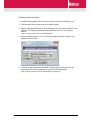
8.2 Adding a Helvar network
1
Double-click the station’s Driver container to bring up the Driver Manager view.
2
Click the New button to bring up the new network dialog.
3
Select “Helvar Driver Network” from the drop down list, set number to add as 1 and
click OK. This will open up another dialog window in which you can name the
network.
Note: it is only possible to add one Helvar Network
4
Ensure Enabled property is “True” so that raw output can be later viewed in the
application director view.
5
Click OK, to add the HelvarDriverNetwork. A folder named Groups will also be
added at the same time immediately under the HelvarDriverNetwork.
Note: the Groups folder use will be explained later in section 8.4.
HELVAR LTD
6 of 20
Doc. No. D005247 Iss. 3
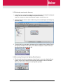
8.3 Performing an automatic discovery
1
In the Nav tree or in the Driver Manager view, double-click the HelvarDriverNetwork
to bring into view the device manager view (Helvar Routers).
Note: this is actually the Helvar Router Manager, Niagara use the term Device.
2
Click the Discover button to start the discovery process and display the Workgroup
selection dialog.
3
The drop down list in the dialog will display all the available Helvar Lighting Router
Workgroups available on the Jace or PC’s Ethernet adaptor’s network. Choose a
Workgroup from this list and click OK.
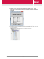
8.4 Discovering Groups in the Lighting Router System
1
The driver will check for the presence of any Groups in use on the Lighting Router
System. If these are found the following dialog will appear to offer an automatic
discovery. Click Yes to accept or No to skip this operation.
HELVAR LTD
7 of 20
Doc. No. D005247 Iss. 3
2
Selecting Yes will, after a short pause display all the available Groups. Use the
check boxes to select the required Groups (all Groups are selected by default) and
click on OK
3
A confirmation dialog is displayed and the Groups are added in the folder under the
HelvarDriverNetwork.
Note: all group types will be discovered from the lighting router system.
HELVAR LTD
8 of 20
Doc. No. D005247 Iss. 3
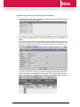
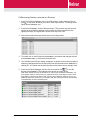
8.5 Discovering Router(s) in a Lighting System Workgroup
1
The initial discovery process completes by displaying a list of Discovered Routers
that belong to the selected Workgroup
2
To commit one or more Lighting Routers to the database: multi-select and drag the
devices to the database pane, or multi-select and click Add. The Add dialog will
appear.
Note: the discovery process will use any natural names that were assigned to devices or
groups during commissioning of the lighting router system. If these contain characters that
are illegal in Niagara component names, they must be corrected (only alphanumeric and
underscore characters are allowed).
3
In general it will not be necessary to make any changes and all the routers shown
can be committed to the database by clicking OK. You should see the device(s)
listed in the Helvar device manager view database, showing the State of “Normal”.
HELVAR LTD
9 of 20
Doc. No. D005247 Iss. 3
4
If a router shows “Request Timeout” check the configuration of the network and/or
the device addresses. You can double-click a router in the device manager to review
settings in the edit dialog.
5
After making any address changes, click save, then right-click the device and select
Actions > Ping to test the connection.
HELVAR LTD
10 of 20
Doc. No. D005247 Iss. 3
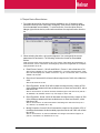
8.6 Discovering Devices connected to a Router(s)
1
In the Helvar Router Manager view, in the Exts column, double-click the Devices
icon
on the router for which you wish to create input devices. This brings up the
Helvar Device Manager view
2
In the Devices Manager, click the Discover button. This process may take several
minutes to complete as it depends on the number of devices connected to the
Lighting Router(s). A progress bar is shown at the top of the view.
3
All the discovered devices are shown at the end of this process.
4
To commit one or more Devices to the database: multi-select and drag the devices
to the database pane, or multi-select and click Add.
5
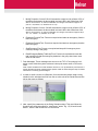
The ‘Add Discovered Device’ dialog will appear. In general it will not be necessary to
make any changes and all the devices shown can be committed to the database by
clicking OK. You should see the device(s) listed in the Helvar device manager view.
6
In the Helvar Device Manager, double click on the points Ext
to view the
devices points database. The example below shows an output device.
Note: when viewing the points for the device on screen, they will refresh immediately. The
same applies when you have points on a graphical PX view. The polling for points is done
sequentially via the devices parent router (one at a time). When the station is running, by
default the points are re-read every 15 minutes. After first creating the device the point data
is retrieved after an initial 15 minute period.
HELVAR LTD
11 of 20
Doc. No. D005247 Iss. 3
8.7 Output Device Direct Actions
1
For output devices a list of actions are also available to you. (If the device type
selected in the drop down menu was “emergency” then the list of actions will differ
from the standard ones available). To select an action, from the Helvar Device
Manger right-click the device, select action and then the required function from the
list.
2
When selecting the action, an input box appears. You must specify the correct
parameters for each action. The following outlines the format for the available
actions.
Note: the result of the action appears in the “Out” column of the Helvar Device Manager. To
clear the result, click on clear result. The Emergency test actions if applicable do not require
input parameters to be set.
a
Recall Scene: format 1,1,90 will recall Block 1, Scene 1, with a fade time of 90.
Note: blocks available are 1-8, scenes available are 1-16, giving 128 total scenes. Fade
time units are displayed as 1/100th of a second. E.g. 90 = 0.9 seconds, 900 = 9 seconds
& 9000 = 90 seconds.
b
Direct Level: format 44,90 will send a direct output level of 44% with a fade time
of 90.
Note: level should be 0-100.
c
Direct Proportion: format 50,90 will increase the output level by a factor of 50%
of the difference between the last recalled scene or direct level and 100%, with a
fade time of 90.
Note: if current level is 44, then an increase of 50% will give a new level of 72 (100-44 =
56, 56x50% = 28, therefore 44+28 = 72). The range is -100 to 100.
d
Direct Proportion: format -20,90 will decrease the output level by a factor of 20%
of the difference between the last recalled scene or direct level and 0%, with a
fade time of 90.
Note: if current level is 44, then a decrease of 20% will give a new level of 35 (0-44 = 44, -44x20% = 9, therefore 44-9 = 35).
e
Modify Proportion: format 5,90 will increase the output level by a factor of 5% of
the difference between the last recalled proportional level and 100% with a fade
time of 90.
Note: if current level is 72, then a modification of 5 will give a new level of approx 74
(100-72 = 28, 28x5% = 2, therefore 72+2 = 74).
HELVAR LTD
12 of 20
Doc. No. D005247 Iss. 3
f
Modify Proportion: format -5,90 will decrease the output level by a factor of 5% of
the difference between the last recalled proportional level and 100% with a fade
time of 90.
Note: if current level is 72, then a modification of 5 will give a new level of approx 68 (072 = -72, -72x5% = -4, therefore 72-4 = 68).
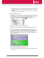
8.8 Viewing Virtual Components
1
As explained previously a folder named Groups is automatically created under the
HelvarDriverNetwork and all discovered group components are stored in this folder.
This ensures that the groups can locate routers and execute actions.
Note: If a group component is added manually it MUST be stored in the Groups folder.
2
Double-click on the Groups folder to open its wiresheet.
3
The wiresheet will display a cascaded view of all discovered group components.
4
The example below shows a typical Group component from the wiresheet.
Note: As soon as the Group is added to the wiresheet it will automatically retrieve the group
properties (Group description, LSIG, LSIBlock 1, LSIBlock 2 and Power Consumption –
described in the next section. The properties will automatically poll and update every 15
minutes. If a push message (described on page 15) is retrieved, the group immediately
updates the LSIG property.
5
Group component properties are described below:
a
HELVAR LTD
Group ID: This is the group number with which the virtual component controls
and interacts.
13 of 20
Doc. No. D005247 Iss. 3
b
Cluster ID: This must be the same as the cluster as used in the address
structure.
Note: Address scheme is described in full on page 20 of this document.
c
Description: This is the group description as obtained by the driver from the
Helvar Router system.
d
LSIG: This is the last scene selected in the group.
Note: This property is updated in response to a push message received from the Helvar
Lighting Router System.
e
LSIBlock 1: This is the last scene selected within the group for block 1.
Note: blocks available are 1-8.
f
LSIBlock 2: This is the last scene selected within the group for block 2.
Note: blocks available are 1-8.
g
Power Consumption: This is the total calculated power consumption for all
devices in the same group.
Note: The value returned will depend on the total consumption at 100% as set in the
Helvar lighting system for that device. The value is not measured but calculated based
on the device type and internal dimming curve and output value.
6
A list of actions is also available to you from the Group component. To select an
action, right-click the device, select action and then the required function from the
list.
Note: the format of the actions is similar to device actions, they are however applied at the
Group level. The Emergency test actions listed do not require input parameters to be set.
a
Recall Scene: format 1,1,90 will recall Block 1, Scene 1, with a fade time of 90.
Note: blocks available are 1-8, scenes available are 1-16, giving 128 total scenes. Fade
time units are displayed as 1/100th of a second. E.g. 90 = 0.9 seconds, 900 = 9 seconds
& 9000 = 90 seconds.
b
Store Scene: Format 1,1 will store the current output values into Block 1, Scene
1 immediately.
Note: blocks available are 1-8, scenes available are 1-16, giving 128 total scenes.
c
Direct Level: format 44,90 will send a direct output level of 44% with a fade time
of 90.
Note: level should be 0-100.
d
Direct Proportion: format 50,90 will increase the output level by a factor of 50%
of the difference between the last recalled level and 100%, with a fade time of
90.
Note: if current level is 44, then an increase of 50% will give a new level of 72 (100-44 =
56, 56x50% = 28, therefore 44+28 = 72). The range is -100 to 100.
e
Direct Proportion: format -20,90 will decrease the output level by a factor of 20%
of the difference between the last recalled level and 0%, with a fade time of 90.
Note: if current level is 44, then a decrease of 20% will give a new level of 35 (0-44 = 44, -44x20% = 9, therefore 44-9 = 35).
HELVAR LTD
14 of 20
Doc. No. D005247 Iss. 3
f
Modify Proportion: format 5,90 will increase the output level by a factor of 5% of
the difference between the last recalled level and 100% with a fade time of 90.
Note: if current level is 72, then a modification of 5 will give a new level of approx 74
(100-72 = 28, 28x5% = 2, therefore 72+2 = 74).
g
Modify Proportion: format -5,90 will decrease the output level by a factor of 5% of
the difference between the last recalled level and 100% with a fade time of 90.
Note: if current level is 72, then a modification of 5 will give a new level of approx 68 (072 = -72, -72x5% = -4, therefore 72-4 = 68).
7
h
EmergencyFunctionTest: Format not required and starts an emergency function
test in the group.
i
EmergencyDurationTest: Format not required and starts an emergency duration
test in the group.
j
StopEmergencyTest: Format not required and stops ALL emergency tests
currently running in the group.
k
ResetEmergencyBatteryTotalLampTime: Format not required and resets the
total running time that the emergency batteries in the group have been used
since the last reset.
Push Messages. These messages are sent on to the TCP / IP bus when a local
action occurs within the system such as a button push scene recall or PIR scene
recall.
Note: Feature available from router firmware versions 4.2.14. By default the push function is
turned off within the Helvar Lighting Router System. Refer to Helvar Designer help for further
information on enabling push messages.
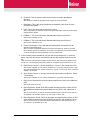
8
In order to recall a scene via a Schedule, from the schedule palette, drag a string
schedule to the wiresheet and link from the out value slot to the Recall scene action
slot on the group as follows:
9
Next, specify the parameters in the String Schedule object. This must follow the
format as previously described for “recall scene” action. E.g. 1,5,90 would recall
Block 1, Scene 5 with a fade time of 0.9 seconds.
HELVAR LTD
15 of 20
Doc. No. D005247 Iss. 3
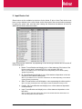
9 Input Device List
Shown below are the available input devices for the Helvar IP driver. Note: Each device must
have a unique Address in the correct format, as this forms part of the communication messages
for polling the points. Also note that when viewing the extensions the address will have an
additional sub-device reference number.
Input devices points extensions vary depending on the device type selected but will consist off
the following types.
a. Button: Format Boolean and display’s true or false statement if the button of the
Helvar control panel is selected (LED lit) or not selected (LED unlit).
Note: It is possible for one or more LED’s to be lit depending on the Helvar Lighting
System programming.
b. IR: Format Boolean and display’s true or false statement dependent on the last
selected IR of the Helvar control panel.
Note: It is possible for one or more IR’s selections to be made depending on the Helvar
Lighting System programming.
c. Slider: Format Numeric and will display a value representing the sliders position.
Note: The value returned will be in the range 0-51200 incremented in steps of 512.
d. PushOn_Off: Format Boolean and display’s true or false statement dependent
on the last action.
e. Input: Format Boolean and display’s true or false statement dependent on the
last action.
Note: On device type 942, the first four inputs can be either Boolean OR numeric not
both. Unused points should be deleted.
HELVAR LTD
16 of 20
Doc. No. D005247 Iss. 3
f.
Input_numeric: Format Numeric and will display a value representing the sliders
position.
Note: The value returned will be in the range 0-51200 incremented in steps of 512.
Further note Input_numeric are only available on device type 942, where the first four
inputs can be either Boolean OR numeric not both. Unused points should be deleted.
g. PIR: Format Boolean and display’s true or false statement dependent on the last
action.
Note: Status shown is PIR active or not active state and does not account for PIR
timeouts and therefore should not be used to validate if lighting levels are on or off.
h. LightSensor: Format Numeric and will display a value representing the current
light value detected.
Note: The value returned will be in the range 0-200. Further note the light sensor value is
an internal system value and does not represent a LUX or any other internationally
recognised measurement of light.
HELVAR LTD
17 of 20
Doc. No. D005247 Iss. 3
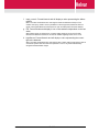
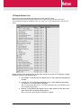
10 Output Device List
Shown below are the available output devices for the Helvar IP driver.
Note: Each device must have a unique Address in the correct format, as this forms part of the
communication messages for polling the points. For clarity only 1 off each ballast type si and iDim are
shown.
Output devices point extensions are all the same except for the device “Emergency Lighting”,
the points consist off the following types.
a. DeviceState: Format Boolean and display’s true or false statement depending on
the state.
b. LampFailure: Format Boolean and display’s true or false statement depending
on if there is or is not lamp failure detected.
Note: On some output devices (e.g. convertors) lamp failure can only be detected in the
case of all lamps being faulty.
c. Missing: Format Boolean and display’s true or false statement if the device has
gone missing from the Helvar lighting system.
Note: In the case of power failure to luminaire for example.
HELVAR LTD
18 of 20
Doc. No. D005247 Iss. 3
d. Faulty: Format Boolean and display’s true or false statement if the device is
detected as faulty in the Helvar lighting system.
Note: In the case of an internal circuitry failure for example
e. OutputLevel: Format numeric and will display a value representing the current
output of the device.
Note: The value returned will be in the range 0-100 representing 0-100% values
commonly used in scene recall. The actual voltage output will vary dependent on the
device, lamp controlled and internal dimming curve.
f.
PowerConsumption: Format numeric and will display a value representing the
power consumption of the device.
Note: The value returned will depend on the total consumption at 100% as set in the
Helvar lighting system for that device. The value is not measured but calculated based
on the device type and internal dimming curve and output value.
3. Device “Emergency Lighting” point extensions consist of the following types:
a. EmergencyFunctionTestTime: Format String and display’s the time and date for
the last test completed.
Note: If no test has been carried out this will return a null.
b. EmergencyFunctionTestState: Format numeric and will display a value
representing the current test status.
Note: Status values shown below and apply also to EmergencyDurationTestState.
i. 0 = Pass
ii. 1 = Lamp Failure
iii. 2 = Battery Failure
iv. 4 = Faulty
v. 8 = Failure
vi. 16 = Test Pending
vii. 32 = Unknown
c. EmergencyDurationTestTime: Format String and display’s the time and date for
the last test completed.
Note: If no test has been carried out this will return a null.
d. EmergencyDurationTestState: Format numeric and will display a value
representing the current test status.
Note: See previous list for function test.
e. EmergencyBatteryCharge: Format numeric and will display a value representing
the current percentage of battery charge remaining.
f.
EmergencyBatteryTime: Format String and display’s the total running time that
the emergency battery has been in use since the last reset.
g. EmergencyTotalLampTime: Format numeric and display’s the total running time
that the lamp has been in use from any power source since the last reset.
HELVAR LTD
19 of 20
Doc. No. D005247 Iss. 3
11 Helvar system device addressing.
The Helvar lighting router system would consist of a number of routers (910 or 920) that enable
connection to a variety of different inputs and outputs using a different data buses.
The backbone structure of the system uses Ethernet Cat 5 cabling & the TCP/IP protocol. As
such each system (or workgroup) is a cluster of routers. The cluster (3rd Octet in IP addressing)
forms the first part of the unique device address
Each router within the system will then have a unique IP address with the 4th octet providing the
unique router number. This number forms the second digit of the unique device address.
The cluster.router is then followed by a subnet. The subnet refers to the data bus on which
inputs or output devices are connected. Depending on the router type (910 or 920) there are 2
or 4 subnets available. In both case’s subnet 1 & 2 use the DALI protocol. For the 920 you have
additional subnets 3 (using S-Dim) and 4 (DMX).
Following cluster.router.subnet is then the device address. This number is limited by the type of
subnet to which the device is connected and in the case of output devices completes the device
address.
For input devices there is a further sub-device which will refer to a particular property of that
input device for example a control panel (device) would have a number of buttons (sub-device).
So a full address would be written:cluster.router.subnet.address for output devices
cluster.router.subnet.address for input devices
cluster.router.subnet.address.sub-address for input sub-devices
Address structure – additional information for reference
Cluster = the 3rd octet of the IP address range used
th
Router = the 4 octet of the IP address of that particular router
Subnet = the data bus on which devices are connected (Dali 1 = 1, Dali 2 = 2, S-Dim = 3, DMX = 4)
Address = the device address, dependant on the data bus (Dali = 1-64, S-Dim = 1-252, DMX = 1-512)
Sub-address = the sub-device of the device (button, sensor, input etc.)
12 Abbreviations
IP
Internet Protocol
TCP
Transmission Control Protocol
UDP
User Datagram Protocol
DALI
Digital Addressable Lighting Interface
S-Dim
Serial Dimmer Commmunication
DMX
Data Multiplex Unit
HELVAR LTD
20 of 20
Doc. No. D005247 Iss. 3