1
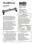
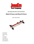
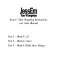
Mortise Mill
User Manual
Model #08100
61 Forest Plain Road,
Orillia, Ontario, Canada
L3V 6H1
866-272-7492 Toll Free
705-726-8233 Local Phone
705-327-0295 Fax
Email: [email protected]
Website: www.jessem.com
IMPORTANT!
WARNING - THIS PRODUCT IS FOR USE
WITH A HAND DRILL ONLY!
WARNING - DO NOT ATTEMPT TO USE THE
MORTISE DRILL BIT (or any drill bit) IN ANY
TYPE OF ROUTER DEVICE AS SERIOUS
INJURY MAY OCCCUR.
READ ADDITIONAL WARNINGS ON PAGE 2
BEFORE USING THIS PRODUCT
Thank you for choosing this product from
JessEm Tool Company. We appreciate your
support and hope that our product serves you
well. This product is designed to provide
many years of reliable service provided it is
used as intended and taken care of.
This user manual will assist you in assembly
and general operation of this product. It is
not our intent to teach you about
woodworking. It is assumed that you are an
experienced woodworker with the basic skills
and experience necessary to use this product
safely. If after reading the following
instructions, if you are unsure or
uncomfortable about safely using this
product we urge you to seek additional
information through widely available
woodworking books or classes.
IMPORTANT!
Read and understand the contents of
this manual before assembly or
operation of this product.
As part of our Continuous Product
Improvement Policy, JessEm products are
always advancing in design and function.
Therefore there may be differences between
what is shown in our catalogs, website or at
retail display and what is sold at time of
purchase. We reserve the right to make
positive changes to our products at our
discretion.
ADDITIONAL RECOMMENDED
TOOLS AND ACCESSORIES
1/2” Hand Drill - Corded or Cordless
1,200 RPM (Min.)
Vacuum (such as Shop Vac)
Vac port is 2-1/4” I.D.
Clamps for holding workpiece
Hardware for mounting jig to workbench
IMPORTANT SAFETY PRECAUTIONS
CONTENTS OF PARTS BAG
(2) - 5/16” X 3/8 shoulder bolts
(1) - 3/4” steel washer
(1) - 7/64” hex wrench
(1) 1/8” hex wrench
(1) 5/32” hex wrench
(1) - 3/16” hex wrench
(1) 3/8” I.D. stop collar w/set screw
(5) Pre-cut tenons
WARNING - DO NOT ATTEMPT TO USE THE
MORTISE DRILL BIT (or any drill bit) IN ANY
TYPE OF ROUTER DEVICE AS SERIOUS INJURY
MAY OCCCUR.
Drill bits are not designed for the high-RPM
output of a Router and could cause the drill bit
to bend and break and cause serious bodily
injury. The mortise drill bits are for use in a
hand drill only.
DO NOT USE A ROUTER OF ANY TYPE WITH
THIS PRODUCT. This product’s guide bushing
and bearings are not designed for the highRPM output of any power router device.
! Before operating any machinery or power
tool, read and understand all safety
instructions in the owner’s manual for the
tool or machine.
! If you do not have a manual, contact the
manufacturer and obtain one before using
any tool or machine.
! Always wear eye protection in compliance
with ANSI safety standards when operating
any power tools or machinery.
! Always use proper guards and safety devices
when operating power tools and machinery.
! Carefully check drill bits before each use. Do
not use if damage or defect is suspected.
! Do not exceed the recommended RPM for
any drill bit.
! Do not wear loose clothing or jewelry that
may catch on tools, machinery or equipment.
! Unplug the tool or machine when mounting
or making any adjustments to mechanical
performance.
FIG. 1
ASSEMBLING THE LEVER SYSTEM
1. The lever system is partially pre-assembled
from the box and needs to be attached to the
Zip Slot Mortise Mill. Using one of the 5/16”
shoulder bolts and a 5/32” hex key from the
parts bag, first attach the long arm of the lever
assembly to the tapped hole in the shaft
mounting block (Fig. 1).
OVERVIEW OF THE ZIP SLOT MORTISE MILL
The Zip Slot Mortise Mill is a unique joinery
system designed to cut mortises in wood for
the purpose of mortise and tenon joinery. This
product offers an excellent means of
positioning a mortise in one workpiece and
then offer the ability to accurately position a
second workpiece to cut another mortise in an
opposing position to the first workpiece. The
result is two separate mortises that are
perfectly aligned and can then joined with a
loose tenon and glue.
Insert washer
here
FIG. 2
2. To assemble the short arm of the lever
system you will first insert a 3/4” steel washer
under the short arm. Again using one of the
5/16” shoulder bolts and a 5/32” hex key
from the parts bag attach the short arm of the
lever assembly to the tapped hole in the
extension of the carriage block. (Fig. 2).
This Model 8100 comes with a 3/8” diameter
mortising drill bit and matching 3/8” drill
guide bushing.
2
ZIP SLOT MORTISE MILL COMPONENTS
TOP VIEW
MORTISE
POSITION SCALE
INDICATOR
BLOCKS
VACUUM
PORT
MORTISE
POSITION
SCALES
CARRIAGE PLATE
ADJUSTMENT
KNOBS
MORTISE
LOCATOR
MARKS
CARRIAGE STOP
ADJUSTMENT
KNOB
CARRIAGE
STROKE
SCALE
DRILL
GUIDE
BUSHING
FRONT VIEW
VACUUM
PORT
DRILL
GUIDE
BUSHING
SHAFT
MOUNT
BLOCK
LEVER
CARRIAGE
STOP
CARRIAGE
PLATE
STOCK
LOCATING
PLATE
BEARING
COVER
PLATE
CARRIAGE
BLOCK
BASE
3
STOCK
LOCATING
SCALES
A
B
FIG. 3
FIG. 5
INSTALLING THE MORTISE DRILL BIT
AND STOP COLLAR
ADJUSTING THE CARRIAGE PLATE
1. Adjust the carriage plate by loosening the
two brass carriage plate adjusting knobs
(letter “A” in Fig. 4). Then slide the carriage
plate into position while referring to the
mortise position scales (letter “B” in Fig. 4).
1. Slide the stop collar onto the drill bit and
using the 1/8” hex wrench, tighten the set
screw to secure the stop collar in position.
Because of the length of the drill guide
bushing, thickness of carriage plate, etc., you
will need to add 2.4 inches to the desired
depth of the mortise you are cutting (Fig. 3).
2. The mortise position scales (letter “A” in
Fig. 5) are used to position the mortise on the
workpiece. The scale indicator blocks (letter
“B” in Fig. 5) help reference the center of the
mortise. For example, if you are using a 3/4”
thick workpiece and you want the mortise
positioned in the center, set the scale
indicator blocks at 3/8” on the mortise
position scales. Then re-tighten the carriage
plate adjustment knobs to secure the
carriage plate in the desired position.
2. Insert the drill bit into the drill chuck and
tighten the bit securely (Fig. 3).
B
A
Note: Although the scale indicator blocks (B)
are preset in our factory. It may be necessary
to make a slight adjustment of your own. The
scale indicator blocks not only reference the
scale to assist in positioning the mortise, they
also help to align the carriage plate and keep
the mortise parallel to the edge of the
workpiece. If you find the sides of the mortise
are not parallel to the workpiece or the
indicator blocks are not accurately
positioning the mortise, adjust as followsAccurately scribe a line along the length and
center of a 3/4” thick board. Clamp the
board to the base of the Mortise Mill and
check the mortise locator marks under each
side of the carriage block. See figure 7 for an
example of using the mortise locator marks
on the carriage plate. The mortise position
scale indicator blocks should be pointing to
3/8” on the scale.
SLID
E
SLI
DE
A
FIG. 4
SETTING UP THE ZIP SLOT MORTISE MILL
There are three easy steps you need to take
to set-up the Zip Slot Mortise Mill.
1. Set the carriage plate to position the
mortise in the workpiece.
2. Position the workpiece in one of two
ways, visually, or by using the stock locating
plate and stock locating scales.
3. Setting the carriage stroke to establish
the length of the mortise.
4
A
B
A
B
FIG. 6
FIG. 8
POSITIONING THE WORKPIECE VISUALLY
POSITIONING THE WORKPIECE USING
THE STOCK LOCATOR PLATE AND SCALES
1. The next step is to position the workpiece.
This can be done in either of two ways. You
can position the workpiece visually by
scribing a line along the center of the mortise
(letter “A” in Fig. 6). Then scribe an
intersecting line that indicates the centerline
of the drill bit (letter “B” in Fig. 6). Keep in
mind that when you set the carriage stroke,
the scales are based on the centerline of the
drill bit. So if you are using the 3/8” diameter
mortise drill bit, half this dimension is 3/16”.
So instead of scribing line “B” to indicate the
end of the mortise, you need to scribe this
line another 3/16” in from where the end of
the mortise will actually be.
1. Another way to position the workpiece is
to set the stock locator block ( letter “B” in
Fig. 8) and use the stock locating scale (letter
“A” in Fig. 8) to locate the desired position of
the workpiece.
ADJUSTING THE STOCK LOCATOR PLATE
Using the 3/16” hex wrench loosen the two
1/4-20 socket head cap screws to position
the stock locating plate (Fig. 8). The stock
locating plate has a rail on the back side that
slides in the top T-slot in the face of the
Mortise Mill base. This rail will help keep the
stock locator plate square and should be
pressed tightly against the top or bottom
edge of the T-slot to help keep it square. The
stock locating plate also has an angled side
and can be flipped upside down to position a
workpiece at a 45 degree angle.
A
A
B
FIG. 7
C
2. Next position the workpiece under the
carriage plate and against the base of the
mortise mill. Line up the mortise locator
marks on the carriage plate (Fig. 7) with the
lines you scribed in step 1 (Fig. 6) above.
Then clamp the workpiece securely to the
front face of the base of the mortise mill.
STOCK
LOCATING
PLATE
STOP POSITION = A + B - C
(A) = DISTANCE FROM EDGE OF STOCK
(B) = WIDTH OF TENON
(C) = RADIUS OF TENON
FIG. 9
5
As shown in the example in Fig. 9, the
diagram shows a 1-1/4” long tenon (letter
“B”). This tenon is to be positioned 5/8” in
from the edge of the stock (letter “A”) The
tenon thickness is 3/8” with the radius being
3/16” (letter “C”). The formula would then be
1-1/4” + 5/8” = 1-7/8”. Subtract 3/16” and
the stop position would be set at 1-11/16” to
the left of “0” to cut this mortise in this
length and position.
A
B
DETERMINING THE CARRIAGE STROKE
Because the carriage stroke scale references
from the centerline of the mortise drill bit,
you need to subtract the thickness of the
tenon from the width of the tenon to
determine where to set the carriage position
on the scale (Fig. 11).
For example, if you have a 2 inch wide tenon
and you are using the 3/8” diameter mortise
drill bit (for a 3/8” thick tenon) you would
subtract 3/8” from 2” and you would then
need to set the carriage stroke to 1-5/8” on
the scale. With the carriage positioned all the
way to the right side. Refer to the pointer at
the base of the left side of the carriage block
and move this left pointer to 1-5/8” on the
carriage stroke scale. Then position the
carriage stop against the left side of the
carriage block and tighten the brass knob to
hold the stop and set the length of stroke for
the carriage.
C
FIG. 10
SETTING THE CARRIAGE STROKE
1. The final step in the set-up is to set the
carriage stroke to give the desired length of
the mortise. This is done by referring to the
carriage stroke scale (letter “B” in Fig. 10)
and using the adjustable carriage stop (letter
“A” in Fig. 10) to set the carriage stroke. The
carriage block also has a pointer on each
side (letter “C” in Fig. 10) to help set the
carriage position to the carriage stroke scale.
FIG. 12
CLAMPING THE WORKPIECE HORIZONTALLY
Clamp the workpiece in the horizontal
position to mill a mortise along the side of
the workpiece. Be sure the workpiece is
positioned tight against the adjustable stock
locating plate and the underside of the
carriage plate. Also be sure to clamp the
workpiece securely so that it does not move
during the milling of the mortise (Fig. 12).
CARRIAGE STROKE (A) = B - C
(A) = CARRIAGE STROKE
(B) = WIDTH OF TENON
(C) = THICKNESS OF TENON
C
A
B
FIG. 11
6
2. With one hand holding the drill, insert the
drill into the drill guide bushing. Place your
other hand on the handle for the lever. As you
pull the trigger on the drill begin moving the
lever from side to side (Fig. 15). You should
begin milling the mortise with very little to no
downward pressure on the drill as you slide
the lever from one end of the mortise to the
other. This will give a cleaner cut to the top
edge of the mortise. Once past the surface
you can apply a little more downward
pressure as needed. Continue milling with
drill running and moving the lever from side
to side until the desired depth is
accomplished.
FIG. 13
CLAMPING THE WORKPIECE VERTICALLY
Clamp the workpiece in the vertical position
to mill a mortise in the end of the workpiece.
Be sure the workpiece is positioned tight
against the adjustable stock locating plate
and the underside of the carriage plate. Also
be sure to clamp the workpiece securely so
that it does not move during the milling of
the mortise (Fig. 13).
FIG. 16
CHECKING THE TENON FIT AND ALIGNMENT
It is important to keep in mind that the
scales, carriage stop and stock locating plate
need to be considered as general reference
guides only. Due to the multitude of variables
in tenon dimensions and aligning the position
of mortises it will be necessary to make test
cuts and check for the desired fit of the
mortise and tenons (Fig. 17) rather than rely
on the scales alone. Once the correct settings
are determined and the stops are set to
achieve your desired results, repeatable
accuracy is easy to achieve.
FIG. 14
MILLING THE MORTISE
1. Once you have determined the position of
the workpiece and clamped it securely in
position, insert the drill bit into the drill guide
bushing to begin milling a mortise (Fig. 14).
WITH DRILL RUNNING
GUIDE LEVER FROM
SIDE TO SIDE
LEVER
FIG. 15
FIG. 17
7
Mast R Lift Excel
Mite R Slide
MODEL 06001
The First Integrated
Lift And Phenolic Top
Combination!
MODEL 02201
Mast R Fence
The First Rail Driven
Miter Gauge Offering
Unsurpassed Accuracy
Mast R Lift
MODEL 04001
The Heavy Weight Champion
Of Aluminim Frame
Router Table Fences!
Rout R Lift FX
MODEL 02101
From The Inventor
Of The Router LiftThe Best Made Insert
Lift On The Market!
Find Out More About Our
High Performance Tools At
MODEL 02302
www.jessem.com
A Great 2HP Lift
at a 2HP price!
Tools That Make A Difference!