1
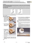
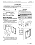
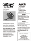
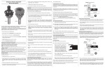
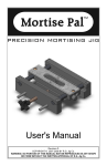
SWINGING DOORS HARDWARE
MULTI--POINT LOCK SYSTEM (AFTER 5/10/99, AMEROCK)
Lock System Installation
YOU WILL NEED TO SUPPLY
Safety glasses
Flat blade screwdriver
Phillips screwdriver
7.
Check passage latch orientation before installing
mortise lock in panel. The beveled side of the passage
latch must face the exterior of the door and be closest
to the panel bottom as shown in illustrations 2 and 3. If
the beveled side of the passage latch is facing the
wrong direction, simply disengage passage latch by
activating the release on the mortise lock, using a
Phillips screwdriver, as shown in illustration 3. Rotate
passage latch 1/2 turn to correct orientation and
engage by pushing latch fully into mortise lock and
releasing. A distinctive click will be heard. See
illustration 3.
8.
Place mortise lock in panel, ensuring passage latch is
oriented as described in previous step. Fasten screw
at top of mortise lock. Replace mortise lock cover.
Fasten to stile with screws by hand with a Phillips
screwdriver. (DO NOT use a power driver). See
illustration 2.
9.
Align and reapply exterior and interior handle
assemblies, fasten with machine screws using a
Phillips screwdriver. (DO NOT use a power driver.)
Lock System Removal
NOTE: When operating multi--point lock, the door panel
should be upright (installed position). This will enable the lock
mechanism to operate without false binding.
1.
Open and detach panel from hinges (DO NOT attempt to
remove adjustable hinge pins, they are not removable),
lay on edge, locking stile up on a clean level surface.
Take appropriate precautions when handling, do not
damage frame, panel or floor.
2.
Remove end bolt guide from top and bottom of panel.
See illustration 1.
3.
Unthread bottom locking rod/end bolt assembly from
mortise lock, pull from stile. See illustration 1.
Mortise lock and hardware
Top locking rod
Interior
handle
assembly
Locking stile
Exterior
multi--point
handle assembly
Cutaway for
illustration
purposes
Bottom locking rod
End bolt
End bolt
guide
Active
panel
mortise
lock
Screw
Bottom rail
1
2
4.
Repeat steps 2 and 3 on top locking rod/end bolt
assembly.
5.
Remove handle assemblies from interior and exterior of
panel. See illustration 2.
6.
Remove Phillips flat head wood screws securing mortise
lock cover plate from panel edge, lift from stile mortise.
Remove screw at top of mortise lock and lift assembly
from stile. See illustration 2.
#8 x 1I
wood screw
3
19970072
2/2005
Exterior handle
assembly
Locking stile
Bottom locking rod
Cover plate
8.1.6
Marvin Service Manual
11708609
SWINGING DOORS HARDWARE
MULTI--POINT LOCK SYSTEM (AFTER 5/10/99, AMEROCK)
IMPORTANT: During the next steps the panel MUST be held
firmly in place on the hinge edge with locking stile up.
10.
Activate head/foot bolt mechanism by depressing
safety trigger and lifting handle.
11.
Slide rod into stile, guide into mortise lock receiver.
Apply slight pressure against end bolt to hold rod.
Rotate clockwise to engage threads in mortise lock.
Locking rod should be fully tightened in 5--6 turns. If not,
reposition rod and repeat procedure.
12.
Repeat above for top locking rod.
13.
Rounded tip on end bolts should be orientated so ramp
is to the interior of panel.
14.
Check lock operation. To avoid false binding, tip panel
upright (as installed) and support off floor 2I (51). This
will give bottom rod assembly clearance to extend.
Depress safety trigger and operate multipoint latch
handle several times, retract end bolts.
15.
Lay panel on hinge stile edge. Check to ensure end
bolts are properly adjusted, install end bolt guides.
16.
Replace panel, check alignment with frame, also check
latch, end bolt and dead bolt operation. Adjust as
needed.
2/2005
8.1.7
Marvin Service Manual
11708609