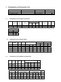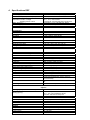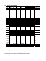
1
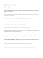
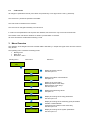
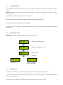
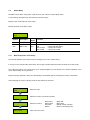
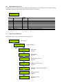
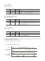
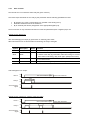
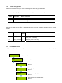
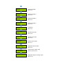
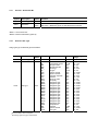
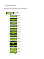
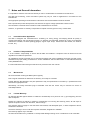
Single Point Controller REx Single Point Gas Controller for Refrigerant Gases User Manual November, 2010 1 Description ................................................................................................................................................ 4 2 Operating Instruction ............................................................................................................................... 5 2.1 2.2 2.3 3 Description Keypad User Interface ..................................................................................................... 5 Setting / Changing Parameters or Set points...................................................................................... 5 Code Levels ........................................................................................................................................ 6 Menu Overview ......................................................................................................................................... 6 3.1 Fault Management .............................................................................................................................. 7 3.1.1 3.1.2 3.1.3 3.2 Acknowledge a Fault.................................................................................................................... 7 Error Memory ............................................................................................................................... 7 System Errors .............................................................................................................................. 8 Status Alarm ........................................................................................................................................ 8 3.3 Status Relay ........................................................................................................................................ 9 3.3.1 Manual Operation of the Relays .................................................................................................. 9 3.4 Menu Measuring Values ................................................................................................................... 10 3.5 Menu Relay Parameters ................................................................................................................... 10 3.5.1 3.5.2 3.5.3 3.5.4 3.5.5 3.5.6 3.6 Menu MP Parameters ....................................................................................................................... 13 3.6.1 3.6.2 3.6.3 3.6.4 3.6.5 3.6.6 3.6.7 3.6.8 3.6.9 3.6.10 3.7 Relay Mode ................................................................................................................................ 11 Relay Function Static / Flash ..................................................................................................... 11 Latching Mode ........................................................................................................................... 11 Horn Function ............................................................................................................................ 12 External Relay Operation ........................................................................................................... 13 Delay Mode of the Relay............................................................................................................ 13 Activate – Deactivate MP ........................................................................................................... 15 Selection Gas Type.................................................................................................................... 15 Measuring Range....................................................................................................................... 16 MP Signal ................................................................................................................................... 16 Threshold / Hysteresis ............................................................................................................... 16 Delay of Alarm ON or OFF......................................................................................................... 16 Control Mode ............................................................................................................................. 17 MP Fault Assigned to Alarm ...................................................................................................... 17 Alarm Assigned to Alarm Relay ................................................................................................. 17 MP Signal Assigned to Analog Output....................................................................................... 17 Menu System Parameters................................................................................................................. 18 3.7.1 3.7.2 3.7.3 Service Mode ............................................................................................................................. 19 Software Version ........................................................................................................................ 19 Maintenance Concept ................................................................................................................ 19 3.7.4 3.7.5 3.7.6 3.7.7 3.7.8 3.7.9 4 Average Function ....................................................................................................................... 20 System Time, System Date ....................................................................................................... 20 Customer Password (Code 1).................................................................................................... 20 Analog Output ............................................................................................................................ 20 Define the Failure Relay ............................................................................................................ 21 Power On Time .......................................................................................................................... 21 Mounting / Electrical Connection ......................................................................................................... 22 4.1 4.2 4.3 5 Electrical Connection ........................................................................................................................ 22 Connection Diagram ......................................................................................................................... 23 Overview REx Module / Connector Block ......................................................................................... 24 Commissioning....................................................................................................................................... 24 5.1 5.2 6 Commissioning .................................................................................................................................. 24 Checklist Commissioning .................................................................................................................. 25 Configuration and Parameter Card....................................................................................................... 26 6.1 6.2 6.3 Configuration Card of System Parameters ....................................................................................... 26 Configuration Card of Alarm Relays ................................................................................................. 26 Configuration Card of Measuring Parameters .................................................................................. 26 7 Specifications REF ................................................................................................................................. 27 8 Gas Sensor .............................................................................................................................................. 28 8.1 Description ........................................................................................................................................ 28 8.2 Calibration ......................................................................................................................................... 28 8.2.1 Zero-Point Calibration ................................................................................................................ 28 8.2.2 Gain Calibration ......................................................................................................................... 28 8.3 Table Overview Gases/ Data ............................................................................................................ 29 8.4 Exchange of Sensor Element............................................................................................................ 29 8.5 Cross-senivity Data ........................................................................................................................... 30 9 Specification Gas Sensor ...................................................................................................................... 30 10 10.1 10.2 10.3 10.4 Notes and General Information ......................................................................................................... 31 Intended Product Application......................................................................................................... 31 Installers` Responsibilities ............................................................................................................. 31 Maintenance .................................................................................................................................. 31 Limited Warranty ........................................................................................................................... 31 Single Point Gas Controller Rex 1 Description The Gas Controller REx is used for measuring, monitoring and warning of refrigerant gases (HFC or HFCF) in the ambient air in the ppm range. The REx is especially employed for monitoring leakages in refrigeration plants to assure the compliance with the requirements according to EN 378. A semi-conductor sensor for refrigerant gases (MP01) is integrated in the gas controller. In addition, an external analog gas transmitter (MP02) can be connected to the controller for monitoring toxic, combustible or refrigerant gases. Four alarm thresholds are free adjustable for each Measuring Point (MP). Every alarm threshold can be assigned to one of the maximum 4 alarm outputs (RX). The Gas Controller can interface via the (0)4 to 20 mA or (0)2 to 10 V output signal with any compatible electronic analog control, DDC/PLC control or automation system. The free adjustable parameters and alarm threshold make a very flexible use in the gas measuring possible. Simple and comfortable commissioning is possible due to factory adjusted parameters. The configuration, parameter settings and operation are easy to do without programming knowledge thanks to the simple, easy-to-handle system menu. The Single Point Gas Controller REx must not be used in potentially explosive atmospheres. The gas controller must only be used within environmental conditions specified in the Technical Data. 2 Operating Instruction The complete configuration, parameterization and service are made via keypad user interface in combination with the display screen. Security is provided via two password levels. 2.1 Description Keypad User Interface Exits programming, returns to the previous menu level. Enters submenus, saves settings. Scrolls up in main menu and submenus, increases or decreases a value. Moves the cursor. LED orange: Flashes when alarm one or more alarms are active. Permanently on, when one of the relays is manually operated. LED red: Flashes when alarm two or more alarms are active. Permanently on, when one of the relays is manually operated. LED yellow: Flashes at system or sensor failure or when maintenance needed. LED green: Power LED 2.2 Setting / Changing Parameters or Set points Open desired menu window. Code window opens, if no code level approved. After input of the valid code the cursor jumps on the first position segment to be changed. Push the cursor onto the position segment, which has to be changed. Change the parameter / set point. Save the changed value. Finish 2.3 Code Levels All changes of parameters and set point values are protected by a four-digit numeric code (= password). The code level 1 permits the operation of the REF. This code level is intended for the customer. The code can be changed individually via code level 2. In code level 2 all parameters and set points are released, this code level is only for the service technician. The release of the code level is deleted if no button is pushed within 15 minutes. All menu windows are visible without entering a code. 3 Menu Overview The operation of the Single Point Gas Controller REF is effected by a simple and logical menu structure which is easy to learn. The operating menu contains the following levels: Starting menu. Main menu Submenu 1 and 2 Starting menu Main menu Submenu Automatikprodukter REF System Errors Status Alarm Status Relay Measuring Values Relay Parameter MP Parameter System Parameter Display and reset of errors See from point 3.1 Displays the status of actual alarms See point 3.2 Display of the relay status Manual operation of the relays Reset function of the relays See from point 3.3 Displays the measuring values See point 3.4 Display and change of the relay parameters See from point 3.5 Display and change of the measuring point parameters Activate or Deactivate MP Assignment of the alarms to the alarm relay See from point 3.6 Display and change of the system parameters See from point 3.7 3.1 Fault Management The integrated fault management records the last 15 faults with date and time stamps in the menu “System Errors“. Additionally a record of the faults occurs in the “Error Memory”, which can be selected and reset only by the service technician. An actual fault is displayed in plain text in the starting menu. The failure relay which is defined in the system parameter “Failure relay“ is activated. The yellow LED in the front of the gas controller flashes. In case of fault of a measuring point (MP) the alarms defined in the menu “MP Parameter” are activated additionally. 3.1.1 Acknowledge a Fault Attention: Acknowledging a fault is only possible after having removed the cause. System Errors Select menu “System Errors” MP 02 < 3mA 05.02 10.38 Example: Failure MP 01 < 3 mA MP 02 < 3mA Reset ?? Reset the fault? Fault reset MP 02 < 3mA Erased Fault reset 3.1.2 or Error still exists Cause not eliminated Reset not possible Error Memory The menu “Error Memory“ in the main menu “System Error” can only be opened via code level 2. In the error memory the last 15 faults are listed for the service technician even if they were already acknowledged in the menu “System Error“. The deletion of each individual message is effected in the same way as the reset of a fault. 3.1.3 System Errors The following system error messages are recorded: MP 02 > 22 mA Cause: Short-circuit at analog input or transmitter not calibrated, detector defective. Solution: Check cable to detector, make calibration, replace the detector. MP 02 < 3 mA Current signal to analog input < 3 mA / 1,3Vdc. (External Detector) Cause: Wire breaking at analog input or detector not calibrated, detector defective. Solution: Check cable to detector, make calibration, replace the detector. Internal communication error I/O Board to LCD Board. GC Error: 3.2 Current signal at analog input > 22 mA / 11Vdc. (External Detector) Cause: Internal error. Solution: Change the Gas Controller module. Maintenance: System maintenance is necessary. Cause: Maintenance date exceeded. Solution: Make the maintenance. Status Alarm Display of the actual alarms in plain text in the order of their arrival. Only those measuring points are displayed, where at least one alarm is active. Changes are not possible in this menu. MP 01 A1 A2 Symbol MP 01 AX Description Measuring (MP) Point No. Status alarm Function A1 = A2 = A3 = A4 = Alarm 1 Alarm 2 Alarm 3 Alarm 4 ON ON ON ON 3.3 Status Relay The REF has two alarm relays (R01 / R02) and two open collector outputs (R03 / R04). In the following description they are referred to as alarm relays. Display of the actual status of alarm relays. Manual operation of the alarm relays. R 01 OFF 3.3.1 Symbol Description R 01 Relay No. 01 OFF Status relay Setting Status OFF Function Select Relay No. OFF = Relay OFF (No gas alarm) ON = Relay ON (Gas alarm) Manual OFF = Relay manual OFF Manual ON = Relay manual ON Manual Operation of the Relays The manual operation of the alarm relays is managed in the menu “Status Relay”. If a relay is in the manual ON or OFF status, the orange/ red alarm LED at the Gas Controller is lit continuously. The external operation of the alarm relay via an assigned digital input has priority to the manual operation in the menu "Status Relay" and to gas alarm. Relays manually operated in the menu “Status Relay” are deleted again by selecting the function "Automatic". Acknowledging the relays in latching mode is also effected in this menu. R 01 OFF Manual ON Manual OFF Manual OFF Select the relay Select the function of manual operation Select the function Take over the function Manual ON Manual OFF Automatic Reset? = Relay ON = Relay OFF = Delete manual operation. = Reset of a latching mode. 3.4 Menu Measuring Values In this menu the current value (CV) and average value (AV) with gas unit and gas type for each active measuring point (MP) is displayed as well as the defined control mode (CV or AV mode). MP 01 R134 ppm 20 AV 33*CV 3.5 Setting Status Symbol Description Function MP 01 R134 ppm CV AV * Not active Error Measuring P. No. Gas type R134 Gas unit Current value CV Average value Control mode Status MP Not active Fault MP Selection of MP No See 3.6.2 See 3.6.2 Current value of gas concentration Average value (10 measured values within the time unit) Display of selected control mode (CV or AV) MP not active Current signal < 3 mA or > 22 mA Menu Relay Parameters Display and change of the parameters for each alarm relay Relay Parameter (Main menu) R 01 (Select relay No.) Relay Mode De- energized Relay mode See 3.5.1 Static / Flash 0s Relay function See 3.5.2 Latching Mode No Time 0s Quitt. 0 Activate latching mode See 3.5.3 DI 0 External Mode DI: ON = 0: OFF = 0 Delay ON Time 0s Delay OFF Time 0s Definition of horn function See 3.5.4 Definition of external relay operation See 3.5.5 Set delay time ON See 3.5.6 Set delay time OFF See 3.5.6 3.5.1 Relay Mode Definition of relay mode: Symbol Description R 01 Relay No. Function Selection of relay DeRelay Mode energized 3.5.2 Setting Status DeDe-energized energized Energized = Alarm ON = Relay ON = Alarm ON = Relay OFF Relay Function Static / Flash Definition of relay function 3.5.3 Symbol Description R 01 Relay No. 0 Function Setting Status Function Selection of relay 0 0 = Relay function static > 0 = Relay function flashing (= Time period in sec.) Impulse / Break = 1:1 Setting Status Function Latching Mode Definition of latching function Symbol Description R 01 Relay No. Selection of relay No Latching Mode No No Yes = Latching mode non active = Latching mode active Acknowledging a latching relay in the menu “Status Relay“ is only possible if the gas concentration is again lower than the alarm threshold including hysteresis. In this case the status latching occurs in the display. Example: Alarm relay R2 with latching mode Alarm 2 On Gas concentration higher Off Display in the Menu Status Relay Relay 2 Reset in the Menu Status Relay R2 Off On Off On Off R2 On R2 On R2 On lower than threshold R2 Latching R2 Off 3.5.4 Horn Function The internal horn is connected to alarm relay R3 (open collector). This alarm output is defined as horn relay by this parameter with the following possibilities to reset. By pressing any of the 4 push-buttons (only possible in the starting menu). Automatic reset at the end of the fixed time. By an external push-button (assignment of the appropriate digital input). The horn function is only activated if at least one of the two parameters (time or digital input) is set. Special function Response After acknowledging the output (by push-button or externally) time starts. When this time has run out and the alarm is still acting, the relay is set again. Symbol Description R 03 Relay No. Quitt Mode Setting Status Function Selection of relay 0 0 = Reset of the relay after time having run out, or by push-button 1 = Reset of the relay by push-button, after time having run out and when alarm is still acting, relay is set again. (Response function). Time 120 Time for automatic reset function or response function 0 = no reset function DI 0 Assignment, which digital input resets the output. Acknowledge the horn output Alarm 3 On Gas concentration higher Of lower than threshold Time Relay 3 On Off Acknowledging signal On Off Special function „Response“. (Return of the horn relay) Alarm 3 On Gas concentration higher Off Time Relay 3 On Off Acknowledgingsignal On Off Time lower than threshold 3.5.5 External Relay Operation Assignment to a digital input (DI) for external switching of the alarm relay (ON and/or OFF). This function has priority to gas alarm and/or manual switching in the menu “Status Relay“. 3.5.6 Symbol Description R 01 DI-ON DI-OFF Relay No. External On External Off Setting Status Function Relay Selection 0 0 If digital input closed, relay switches ON If digital input closed, relay switches OFF Delay Mode of the Relay. Delay time ON starts when the alarm is released and/or delay time OFF starts when the alarm returns to normal condition. 3.6 Setting Status Symbol Description R 01 Relay No. 0s Delay Time ON 0s Delay Time OFF 0 Function Relay Selection Mode ON: Relay is only activated at the end of the defined time (sec.) 0 sec. = No delay 0 Mode OFF: Relay is only deactivated at the end of the defined time (sec.) 0 sec. = No delay Menu MP Parameters Display and change of parameters, assignment of alarms to alarm relays and activation of Measuring Points (MP). MP Parameter (Main Menu) MP 01 active (Selection of MP) MP Mode active Gas Type R134 Measuring Range 2000 ppm MP Signal linear Activate or deactivate MP See 3.6.1 Define gas type See 3.6.2 Define measuring range See 3.6.3 Adjust signal form of the transmitter See 3.6.4 Threshold 1 300 ppm Threshold 2 500 ppm Threshold 3 500 ppm Threshold 4 2000 ppm Hysteresis 50 ppm Delay ON Time 0s Delay OFF Time 0s C/A Mode CV Alarm - 1 2 3 4 Fault - 0 0 0 0 A1; A2; A3; A4 01; 02; 03; 04 Analog Output 0 Define threshold 1 See 3.6.5 Define threshold 2 See 3.6.5 Define threshold 3 See 3.6.5 Define threshold 4 See 3.6.5 Hysteresis See 3.6.5 Set delay time ON See 3.6.6 Set delay time OFF See 3.6.6 Define control mode See 3.6.7 Assign MP fault to alarm See 3.6.8 Assign alarm to alarm relay See 3.6.9 and 3.6.10 Assign MP signal to analog output See 3.6.10 3.6.1 Activate – Deactivate MP Symbol Description MP 01* Measuring point Active MP Status Setting Status Not active Function Selection MP No. Active = Measuring point activated at the controller Not active = Measuring point not activated at the controller *MP01 = On-board sensor *MP02 = External transmitter (optional) 3.6.2 Selection Gas Type Assign gas type to attached gas transmitters. Symbol Description MP 01 Measuring point R134 1 2 Gas type Setting Status Gas type R134 CO Ex NO NO2 NH3 O2 CO2 SO2 H2S CL2 ETC VOC R401 R402 R408 R409 R404 R416 R502 R410 R411 R11 R123 R134 R22 TEM RH CO2 TOX Recommendation without obligation Decreasing signal at oxygen measurement! Carbon monoxide Combustible gases Nitrogen oxide Nitrogen dioxide Ammonia Oxygen2 Carbon dioxide Sulphur dioxide Hydrogen sulphide Chlorine Ethylene oxide Air quality Refrigerant gas Refrigerant gas Refrigerant gas Refrigerant gas Refrigerant gas Refrigerant gas Refrigerant gas Refrigerant gas Refrigerant gas Refrigerant gas Refrigerant gas Refrigerant gas Refrigerant gas Temperature Humidity Carbon dioxide Toxic gas Unit Measuring range1 ppm % LEL ppm ppm ppm %V/V ppm ppm ppm ppm ppm % ppm ppm ppm ppm ppm ppm ppm ppm ppm ppm ppm ppm ppm °C % RH ppm ppm 0 – 300 0 – 100 0 – 50 0 – 25 0 – 300 0 – 25 0 – 2000 0 – 100 0 – 200 0 – 100 0 – 20 0 – 100 0 – 2000 0 – 2000 0 – 2000 0 – 2000 0 – 300 0 – 300 0 – 300 0 – 300 0 – 300 0 – 300 0 – 300 0 – 300 0 – 300 0 – 50 0 – 100 0 – 5000 0 - XX 3.6.3 Measuring Range The measuring range can be defined arbitrarily between 10 and 10000. The measuring ranges in the table Gas Type are only recommendations without obligation. The measuring range for MP01 (integrated gas sensor) is factory set, the measuring range for MP02 must agree with the signal (4 to 20 mA / (0)2 to 10 V) of the attached gas detector. (4 mA / (0)2 V = Display 0 (ppm); 20 mA / 10 V = Display of the ultimate value of the measuring range) 3.6.4 MP Signal Gas transmitters using electro-chemical or catalytic beat gas sensors normally produce a linear 4 to 20 mA / (0)2 to 10 V signal, proportional to the gas concentration. Semiconductor gas sensors produce a non-linear (exponential) signal due to their measuring function. The Single Point Gas Controller REF is prepared for both types of gas transmitters. The classification of signals is defined in this menu. The integrated sensor, however, emits an already linearised signal. Therefore choose “linear” for MP01. 3.6.5 Symbol Description MP 01 Measuring Point Linear MP Signal Setting Status Linear Function Selection of MP No. Linear = Transmitter with linear output signal Non linear = Transmitter with non-linear output signal Threshold / Hysteresis For each measuring point four alarm thresholds are available for free definition. If the gas concentration is higher than the adjusted alarm threshold, the associated alarm is set. If the gas concentration falls below the alarm threshold inclusive hysteresis the alarm is again reset. Unused alarm thresholds have to be defined at measuring range end point, in order to avoid false alarms. At O2 measurement an alarm is released by a decreasing measuring signal! Symbol Description MP 01 300 ppm 3.6.6 Default Status Function Measuring Point Thresholds 300 500 500 2000 50 Threshold 1 Threshold 2 Threshold 3 Threshold 4 Hysteresis Selection MP No. Gas concentration > Threshold 1 = Alarm 1 Gas concentration > Threshold 2 = Alarm 2 Gas concentration > Threshold 3 = Alarm 3 Gas concentration > Threshold 4 = Alarm 4 Gas concentration < (Threshold X –Hysteresis) = Alarm X OFF Delay of Alarm ON or OFF Definition of alarm ON and/or alarm OFF delay. The function applies to all alarms of an MP. Default Status Symbol Description MP 01 Measuring Point 0s Delay Time ON 0s Delay Time OFF 0 0 Function Selection of MP No. Gas concentration > Threshold: Alarm is only activated at the end of the fixed time (sec.). 0 sec. = No Delay Gas concentration < Threshold: Alarm is only deactivated at the end of the fixed time (sec.). 0 sec. = No Delay 3.6.7 Control Mode Definition of the alarm evaluation by means of current (CV) or average value (AV). Symbol MP 01 CV Default Function Status t Measuring Point Selection of MP No. CV = Control by the current gas value Evaluation CV AV = Control by the average gas value Description Current- average value function see: 3.7.4 3.6.8 MP Fault Assigned to Alarm Definition, which alarms are activated in case of a fault at the measuring point. Symbol Description MP 01 Alarm - 1 2 3 4 Fault - 0 0 0 0 Measuring Point 3.6.9 Failure MP Default Status 0000 Function Selection of MP No. 0 = Alarm not ON at MP failure 1 = Alarm ON at MP failure Alarm Assigned to Alarm Relay Each of the 4 alarms can be assigned to any alarm relay. Unused alarms are not assigned to any alarm relay. Symbol Description MP 01 Measuring Point 1 A1 A2 A3 A4 3.6.10 Default Status Function Selection of MP No. 01 02 03 04 01 = Alarm 1 activates alarm relay R 01 02 = Alarm 2 activates alarm relay R 02 03 = Alarm 3 activates alarm relay R 03 00 = Alarm 4 doesn’t activate any alarm relay MP Signal Assigned to Analog Output The measuring point signal can be assigned to the analog output. At this the signal defined in the control mode (current or average value) is transmitted. Analog output see also: 3.7.7 Symbol Description MP 01 Measuring Point 0 A Default Status 0 Function Selection of MP No. 0 = MP Signal not assigned to analog output 1 = MP Signal assigned to analog output 1 3.7 Menu System Parameters Displays and changes the system parameters of the Gas Controller module. System Parameter (Main Menu) Service Mode OFF See 3.7.1 Software Version REF See 3.7.2 Next Maint. Date TT.MM.JJ See 3.7.3 Service Phone +46(0) 31-287202 See 3.7.3 AV Overlay 120 s. 120 ppm See 3.7.4 AV Time 1800 s See 3.7.4 Time System EU See 3.7.5 Time hh:mm:ss See 3.7.5 Date TT.MM.JJ See 3.7.5 Customer Pass Change **** See 3.7.6 Failure Relay XX See 3.7.8 Power On Time 30 s See 3.7.9 Analog Output 3.7.1 Analog Output 1 Max. See 3.7.7 Calibration AO 1 Siehe 4.0=4 mA 20 = 20mA See 3.7.7 Service Mode When the service mode is active (ON) the alarms are not transmitted to the alarm relays (in case of calibration or service work). The service mode is reset automatically after 60 minutes or manually in the menu “Service Mode”. 3.7.2 3.7.3 Symbol Description Default Status Function Off Service Mode Off Off = Alarms activate the associated alarm relays On = Alarms are not transmitted to the alarm relays Default Status Function Software Version Symbol Description GC03XX Software Version XX = Software Version Maintenance Concept Integrated in the REF system there is a control of the maintenance intervals required by law or by the customer. At commissioning or after maintenance the date for the next maintenance is entered. When reaching this date the failure signal is activated the following morning at 9 o’clock, and the phone no. of the service technician occurs in the display. The fault signal (maintenance) can be acknowledged by the operator. The maintenance message (service phone no.) is reset by entering the next maintenance date after having accomplished the maintenance. See also 3.7.5 The service phone no. can be entered individually in the next menu. Symbol Description TT.MM.JJ Maintenance Date 0853.... Phone No. Default Status Function TT.MM.JJ = Input of the date for the next maintenance Input of the individual service phone no. 3.7.4 Average Function For each active measuring point the Single Point Gas Controller calculates the arithmetic average value out of 10 measurements got within the time unit defined in the menu “AV Time“. This average value is indicated in the menu “Measuring Values” next to the current value. At each measuring point the control mode (current or average value) is defined for the alarm evaluation. The alarm evaluation of the control mode average value is overlaid by the current value, when the current value exceeds the alarm threshold defined in the menu “AV Overlay“. The overlay is delayed by the time factor defined in this menu. Whit time factor 0 sec. the overlay is not active. Symbol 120 s 120 ppm 1800 s 3.7.5 Description AV Overlay AV Time Default Status 120 s 120 ppm 1800 s Function sec. = Delay time of average value overlay. ppm = Alarm threshold of average overlay sec. = Time for the calculation of the average value System Time, System Date Time and date have no memory back up; therefore after each power supply OFF-ON time and date restart. Input and correction of time and date. Selection of the time and date format. Symbol Description Default Status EU Time format EU hh.mm.ss Time EU = Display of time and date in EU format US = Display of time and date in US format hh.mm.ss = Input of the correct time (EU format) hh.mm.ss am = Input of the correct time (US format) TT.MM.JJ = Input of the correct date (EU format) MM.TT.JJ = Input of the correct date (US format) TT.MM.JJ Date 3.7.6 Function Customer Password (Code 1) Change the system password for level 1 3.7.7 Symbol Description Default Status Function 1234 Customer Password 1234 1234 = Define the customer’s password with 4 characters Analog Output The Single Point Gas Controller has one analog output (AO01) with (0)4 to 20 mA / (0)2 to 10 V signal. The signal of MP01 or/and MP02 can be assigned to the analog output. The assignment is effected in the menu “MP Parameters“ for each MP. The measuring point sends the signal, which is defined in the menu “C/A Mode“. The output signal (mA / V) and starting point (0 / 20%) is selected at the I/O Board by means of jumper. See fig. 4. Out of the signals of all assigned measuring points the Single Point Gas Controller determines the minimum, the maximum or the average value and transmits it to the analog output. The definition, which value is transmitted, is effected in the menu “Analog Output 1“. The analog output can be calibrated at 4 and at 20 mA, only in mA mode. Therefore an ampere meter (measuring range 25 mA) can be attached to the AO and the respective factor has to be changed until the analog output corresponds to 4 and/or 20 mA. During calibration evaluation of the measuring point signals is not possible. This calibration is effected by the factory. The factors shall not be changed. 3.7.8 Default Status Symbol Description Max. Select Max. Output Mode 4.0 20.0 Calibration 4.0 20.0 Function Min. = Displays the minimum value of all assigned MP Max. = Displays the maximum value of all assigned MP Average = Displays the average value of all assigned MP 4. 20.0 = Calibration factor at 4 mA = Calibration factor at 20 mA Define the Failure Relay Definition of the failure relay. See also fault management (3.1) 3.7.9 Symbol Description 0X Fault Relay Default Status R0X Function R0X = Define the fault relay Power On Time Gas sensors need a running-in period, until the chemical process of the sensor reaches stable conditions. During this running-in period the current signal can lead to an unwanted releasing of a pseudo alarm. Therefore the power on time is started at the REF after having switched on the power supply. While this time is running out, the Gas Controller does not activate any alarms. The power on status occurs in the starting menu. Symbol Description 30 s Power On Time Default Status 30 s Function XX = Define the power on time (sec.) 4 Mounting / Electrical Connection The Gas Controller is fixed to the wall through the 4 marked mounting holes at the back side of the housing. These mounting holes are accessible after opening the housing. For mounting you additionally have to plug off the PCB. See fig. 01. The mounting holes are covered with the enclosed caps after the end of the installation. We recommend considering the following when choosing the mounting position: The installation height depends on the gas type to be detected. For gases whose specific weight is higher than that of air the installation is near the ground. For gases with a specific weight lower than that of air installation has to be at the highest point possible. Cables are inserted from below. Keep a minimum distance of 150 mm on the right side in order to open the stainless steel housing. Customer’s instructions. 85 mm 42 mm 113 mm d = 5 mm 84 mm 135 mm 82 mm 125 mm Mounting d = 5 mm Fig. 01 4.1 Standard plastic housing Stainless steel housing Electrical Connection The technical requirements and regulations for wiring, electrical security, as well as project specific and environmental conditions etc. must be observed when mounting. The electrical installation may only be completed by a qualified electrician in full compliance with pertinent regulations. We recommend the following cable types1 1 Power supply J-Y(St)Y 2x2 x 0,8 Alarm relay J-Y(St)Y 2x2 x 0,8 Gas transmitter J-Y(St)Y 2x2 x 0,8 The recommendation does not consider local conditions such as fire protection etc. For the exact position of the terminals see the following connection diagram. 4.2 Connection Diagram Connection diagram with an optional 4 to 20 mA transmitter* Fig. 2 Connection diagram with an optional (0) 2 to 10 V transmitter* Fig. 3 * The analog input function is determined by the hardware. Each PCB has got a label with the specific type. See fig. 4. 4.3 Overview REF Module / Connector Block 1 2 3 4 6 7 8 9 10 1 2 3 4 5 6 7 X4 X5 Fig. 4 Fig. 5 Selection of the analog output signal Jumper 0- 20 % Jumper V-A Output signal Not set Not set 0 – 20 mA Set Not set 4 – 20 mA Not set Set 0 – 10 V Set Set 2 5. Commissioning 2.1 Commissioning – 10 V Prior to commissioning, the wiring of the REF including all field devices must be completely terminated! Check the optional external transmitter input signal, it has to be the same as indicated on the label of the PCB. See fig. 4 Select the contact for relay No. 2 with jumper NC/NO. See fig. 2/3 and 4. Select the analog output signal with jumper V-A and 0-20%. See fig. 4. After switching the power supply “ON” and at the end of the Power ON Time, the REF is ready for use. The REF is delivered with standard parameters and set points. The registration of the optional external gas transmitter and the assignment of the alarm relays to the individual alarms must always be performed during commissioning. Additionally all other parameters have to be checked and adapted to the local conditions. The standard parameters can be taken from the following configuration and parameter card. We recommend registering the individual parameters and set points into the list. We recommend checking the parameters and set points according to the following check list. 2.2 Checklist Commissioning System Parameter Finished Parameter Time and date Parameter of average function Password level 1 (customer’s password) Function analog output Define fault relay Power ON time Service phone no. Maintenance date Relay Parameter Parameter Relay R 1 Finished 2 3 Relay mode Function static / flash Latching mode Horn function External relay operation Delay ON time Delay OFF time MP Parameter Finished Parameter MP No. MP mode Gas type Measuring range MP signal Threshold 1 Threshold 2 Threshold 3 Threshold 4 Hysteresis Delay ON time Delay OFF time C/A mode Assigned failure <> alarm Assigned alarm <> alarm relay Assig. MP sig. <> analog output 1 1 1 2 MP 01 = On Board Sensor, MP 02 = external Transmitter 4 3 Configuration and Parameter Card Commission: Customer: Commissioning - Company Commissioning - Date 3.1 Project No. Service Technician Configuration Card of System Parameters Service Software MaintenVersion ance Date Default GC 03 06.06.08 Service Phone AV Overlay Time Costumer Power Pass ON ppm Time AV System Time Time 120 120 1800 EU 1234 30 s 0853190040 Analog Output 1 Calibration Mode = 4 = 20 Max. 4.0 20.0 3.2 Configuration Card of Alarm Relays Relay No. Mode Default Energized R01 R02 R03 R04 3.3 Static Latching Flash Mode 0s No Horn Function Time Quitt 0 0 External ON OFF DI DI 0 0 DI 0 Configuration Card of Measuring Parameters Meas MP uring Signal Range MP No. MP Gas Status Type De fault 01 02 Not R134 2000 Linear active Delay Time (sec.) ON OFF 0 0 CV/ AV CV Thresholds A1 A2 A3 A4 300 500 500 2000 Assigned MP Fault < >Alarm A1 A2 A3 A4 0 0 0 Hyst 0 50 Assigned Alarm <> Alarm Relay A1 A2 A3 A4 R1 R2 R3 R4 AO 0 Delay Time ON OFF DI DI 0 0 Fault Relay 0 4 Specifications REF Electrical Power supply Power consumption (without options) Analog output signal Selectable: Current / Voltage : Starting point 0 or 20% Alarm relay (R1) Alarm relay (R2) Binary output (R3; R4) 18 – 28 VDC/AC, reverse polarity protected 120 mA, max. 2,9 VA (0) 4 – 20 mA, load 500 Ω (0) 2 – 10 V, load ≥ 50 kΩ Proportional, overload and short-circuit-proof 30 VAC/DC, 0,5 A, potential-free, SPDT 30 VAC/DC, 0,5 A, potential-free, SPNO/SPNC 30 VDC, 0,05 A open collector output Visualization Display Status LED (4) Operation Two lines, each 16 characters Normal operation- Fault- Alarm 1- Alarm 2 4 push- buttons, menu-driven Operation Environment Humidity Working temperature Storage temperature Pressure range 15 – 90 % RH non condensing - 10° C to + 40° C (14 °F to 104 °F) 5° C to + 30° C (41 °F to 86 °F) Atmospheric ± 10 % Physical Enclosure stainless steel, type 5 Colour Dimensions (W x H x D) Weight Protection class Installation Enclosure plastic version, type 0 / 7 Colour Dimensions type 0 (W x H x D) Dimensions type 7 (W x H x D) Weight Protection Installation Cable entry Wire connection Guidelines Warranty Stainless steel V2A Natural, brushed 113 x 135 x 45 mm (4.48 x 5.35 x 1.8 in.) Approx. 0,6 kg (1.32 Ibs.) IP 55 Wall mounting, pillar mounting Plastics GWPLAST RAL 7032 (light grey) 87 x 127 x 56 mm (3.43 x 5.0 x 2.2 in.) 114 x 156 x 75 mm (4.49 x 6.14 x 2.95 in.) Approx. 0,4 kg (0.9 Ibs.) IP 55 Wall mounting Standard 2 x M 20 Screw type terminals min. 0,25 to 2,5 mm2 (14 to 30 AWG) EMC Guidelines 2004/108 /EEC CE 1 year on material (without sensor) Options Analog input (external transmitter) Analog input (1) Power supply for external analog transmitter Buzzer Acoustic pressure Frequency Serial Interface Transceiver Heating Temperature controlled Ambient temperature Power supply Power consumption 4 – 20 mA, input resistance 200 , (0) 2 – 10V, input resistance 25 k, overload- and short-circuit-proof 24Vdc max. 50 mA 83 dB (A) (distance 200 mm) (0.7 ft) 2300 Hz RS 485 / 19200 Baud 3 ± 2 °C (38 °F ± 3.6 °F) -20 °C (-4 °F) 18 – 20 VDC 0,3 A; 7,5 VA 5 Gas Sensor 5.1 Description A semi-conductor sensor is integrated in the REF. The ambient air being monitored diffuses through a metal grid into the sensor. The gas oxidises at the heated detector element (metallic oxide) and changes the conductivity in dependence of the gas concentration. This non-linear alteration of the conductivity is evaluated by the internal sensor electronics and linearised by the micro-processor. The temperature compensation is also integrated in the transmitter. Oxidation processes lead by-and-by to an unwanted influence on the alteration of the conductivity. Therefore regular calibrations of zero-point (Zero) and gain are necessary. Caution: Certain substances and gases in the atmosphere being monitored can affect the sensitivity of the refrigerant gas sensor element and/or poison the sensor completely. The following are currently known: Silicones. Corrosive substances, like H2S, SOx, Cl2, HCl, etc. can lead to corrosion and damage of the sensor. Alkaline metals cause a considerable drift of the sensor. 5.2 Calibration Required instruments to calibrate the transmitter: Test gas bottle with refrigerant test gas* in the range of 1000 ppm for measuring range of 2000 ppm or 100 ppm for measuring range 300 ppm. Gas pressure regulator with flow meter to control the gas flow to 300 ml/min. Calibration adapter with tube, (silicon-free, e.g. Viton). Calibration set AT 1110S02. See fig. 06. Digital voltmeter with range 0 – 10 VDC, accuracy 1% A small screwdriver. *Test gas R 22 or R134a, depending on the used sensor, see table Overview Gases/ Data. 5.2.1 Zero-Point Calibration The zero-point calibration of the sensor is not necessary, because the zero-point of the output signal has already been factory-calibrated. 5.2.2 Gain Calibration Attention: Refrigerant calibration gas is toxic, never inhale the gas! Symptoms: Dizziness, headache and nausea. Procedure if exposed: Take the victim into fresh air at once, call a doctor. Prior to calibration the sensor element must be fully stabilized by applying power voltage for at least 8 days without interruption. . Please observe proper handling procedures for test gas bottles (regulations TRGS 220)! Open window MP 01 in the menu “Measuring Value”. Connect digital voltmeter to pin “Bridge” (-) and ground (X4 pin 2). See fig. 4. Connect calibration adapter carefully to the sensor element. Apply calibration test gas 100 ppm or 1000 ppm (300 ml/min; 1 Bar (14.5 psi) ± 10%). Wait three minutes until the value is stable; adjust calibration voltage with potentiometer ”Zero” to the value according to the table Overview Gases/ Data. Then adjust the display value to the calibration gas value with the potentiometer “Gain”. Remove calibration adapter with a careful light turn. Check the sensor for correct mounting! By limiting the gain factor, calibration will not be possible any more when the sensitivity of the sensor reaches a residual sensitivity of 30%. Then the sensor has to be replaces. 5.3 Table Overview Gases/ Data Gas HFC type HCFC R 22 R 401a R 401b R 401c R 402a R 402b R 403a R 403b R 405a R 406a R 408a R 409a R 409b R 411a R 411b R 412a R 509a R 134a R 404a R407a R407b R407c R413a R 416a R417a R 507 R 410a R11 R12 R133 5.4 Sensor type TGS 830 TGS 830 TGS 830 TGS 830 TGS 830 TGS 830 TGS 830 TGS 830 TGS 830 TGS 830 TGS 830 TGS 830 TGS 830 TGS 830 TGS 830 TGS 830 TGS 830 SP42A TGS 832 SP42A TGS 832 SP42A TGS 832 SP42A TGS 832 SP42A TGS 832 SP42A TGS 832 SP42A TGS 832 SP42A TGS 832 SP42A TGS 832 SP42A TGS 832 TGS 830 TGS 830 TGS 830 Group HCFC HCFC HCFC HCFC HCFC HCFC HCFC HCFC HCFC HCFC HCFC HCFC HCFC HCFC HCFC HCFC HCFC HFC HFC HFC HFC HFC HFC HFC HFC HFC HFC HFC HFC HFC HFC HFC HFC HFC HFC HFC HFC CFC CFC CFC Measuring range 2000 ppm 2000 ppm 2000 ppm 2000 ppm 2000 ppm 2000 ppm 2000 ppm 2000 ppm 2000 ppm 2000 ppm 2000 ppm 2000 ppm 2000 ppm 2000 ppm 2000 ppm 2000 ppm 2000 ppm 300 ppm 2000 ppm 300 ppm 2000 ppm 300 ppm 2000 ppm 300 ppm 2000 ppm 300 ppm 2000 ppm 300 ppm 2000 ppm 300 ppm 2000 ppm 300 ppm 2000 ppm 300 ppm 2000 ppm 300 ppm 2000 ppm 2000 ppm 2000 ppm 2000 ppm Calibration Gas (ppm) Volt. (mV) R22 1000 3165 R22 1000 3165 R22 1000 3165 R22 1000 3165 R22 1000 3165 R22 1000 3165 R22 1000 3165 R22 1000 3165 R22 1000 3165 R22 1000 3165 R22 1000 3165 R22 1000 3165 R22 1000 3165 R22 1000 3165 R22 1000 3165 R22 1000 3165 R22 1000 3165 R134a 100 1665 R134a 1000 3165 R134a 100 1665 R134a 1000 3165 R134a 100 1665 R134a 1000 3165 R134a 100 1665 R134a 1000 3165 R134a 100 1665 R134a 1000 3165 R134a 100 1665 R134a 1000 3165 R134a 100 1665 R134a 1000 3165 R134a 100 1665 R134a 1000 3165 R134a 100 1665 R134a 1000 3165 R134a 100 1665 R134a 1000 3165 XX XX XX XX XX XX Relative density (air =1) > air > air > air > air > air > air > air > air > air > air > air >1 3,45 > air 3,45 2,3 Exchange of Sensor Element Sensor has to be replaced completely including the electronics. The replacement electronics with the new sensor is already factory-calibrated. After exchange of the electronics the REF parameters have to be checked and adjusted if necessary. 5.5 Cross-sensitivity Data Sensor Gas Formula TGS 830 TGS 832 Ethanol Ethanol Ethanol SP42A Iso-butane C2H8O C2H8O C2H8O C4H10 <1 <1 <1 <1 Methane CH4 <<1 6 Reaction Specification Gas Sensor Sensor performances Gas type Sensor element Measuring range Refrigerant gases, see table Gases/ Data Semi-conductor sensor 20 – 300 / 20 - 2000 ppm Response time Repeatability Oxygen concentration ± 20 % 21 % (standard) 18 % minimum level Life expectancy Temperature range Humidity > 5 years/normal operating environment - 10 °C to + 50 °C (14°F to 122 °F) 5 – 95 % RH non condensing Pressure range Storage temperature range Storage time Atmosphere ± 10 % 0 °C to 50 °C (32 °F to 122 °F) Max. 12 months Mounting height Depending on gas type Calibration adapter Fig. 6 Type: Calibr-set- t90 < 40 sec. 7 Notes and General Information It is important to read this user manual carefully in order to understand the information and instructions. The REF gas monitoring, control and alarm system may only be used for applications in accordance to the intended use. The appropriate operating and maintenance instructions and recommendations must be followed. Due to permanent product developments, AP reserves the right to change specifications without notice. The information contained herein is based on data considered to be accurate. However, no guarantee or warranty is expressed or implied concerning the accuracy of these data. 7.1 Intended Product Application The REF is designed and manufactured for controlling, for saving energy and keeping OSHA air quality in commercial buildings and manufacturing plants (i.e. detection and automatic exhaust fan control for automotive maintenance facilities, enclosed parking garages, engine repair shops, warehouses with forklifts, fire stations, tunnels, etc.). 7.2 Installers` Responsibilities It is the installer’s responsibility to ensure that all REF are installed in compliance with all national and local regulations and OSHA requirements. All installations shall be executed only by technicians familiar with proper installation techniques and with codes, standards and proper safety procedures for control installations and the latest edition of the National Electrical Code (ANSI/NFPA70). It is also essential to follow strictly all instructions as provided in the user manual. 7.3 Maintenance We recommended checking the REF system regularly. Due to regular maintenance differences in efficiency can easily be corrected. Limited Warranty Re-calibration and part replacement may be implemented in the field by a qualified technician and with the appropriate tools. Alternatively, the easily removable plug-in transmitter card with the sensor may be returned for service to Automatikprodukter. 7.4 Limited Warranty AP warrants the REF against defects in material or workmanship for a period of one (1) year beginning from the date of shipment. Should any evidence of defects in material or workmanship occur during the warranty period, AP will repair or replace the product at their own discretion, without charge. This warranty does not apply to units that have been altered, had attempted repair, or been subjected to abuse, accidental or otherwise. The above warranty is in lieu of all other express warranties, obligations or liabilities. This warranty applies only to the REF. AP shall not be liable for any incidental or consequential damages arising out of or related to the use of the REF.