1
WOLF
Automatic digital measuring and
monitoring system for FM networks
User manual
Installation and use of
the Wolf device and software
(Rev. 1.1 ENG)
ITA
SAFETY WARNINGS / ISTRUZIONI PER LA SICUREZZA
THANK YOU FOR CHOOSING AXEL TECHNOLOGY
WOLF
The Wolf is the leading automatic digital measuring and monitoring system for FM networks. It can monitor
analog audio signals, AES/EBU and MPX + RDS or RBDS digital signals and RF signals. It monitors the
quality of the FM signal transmitted in off-air mode and is a powerful and intelligent automatic changeover
device that works between all inputs. It filters all RDS units and - using a local coder - it regenerates a UECP
stream for other coders, as well as managing alarms, and its switching policy is user-settable. It is
combinable with WOLF networks for comparative measurements and automatic tests on the network, with
on-air mode option. Wolf features the following inputs: 2 analog audio, 2 AES/EBU audio, MPX 3, 1 Tuner.
Outputs featured are: 2 analog audio and 2 AES/EBU audio. It includes: 2 quality MPX decoders, 4 MPX
detectors, 3 RS232 ports, 2 RDS decoders, 4 GPIO interfaces and 4 relays. All contained in a single device,
the WOLF
Summing up, the WOLF offers:
Dual stereo analog audio input with bandwidth 20Hz - 20Khz.
Dual AES/EBU digital audio input with sampling frequency 44.1kHz to 96kHz.
Dual MPX input with bandwidth up to 59Khz.
Dual stereo analog audio output with bandwidth 20Hz -20Khz.
AES/EBU digital stereo output with bandwidth 20kHz (and sampling frequency 44.1kHz to 96kHz).
Digital Stereo MPX decoder.
Built-in FM tuner.
Built-in RDS decoder
Input for external tuner (for use of a higher quality FM receiver than the built-in one).
Ethernet interface with web server, SNMP agent and UECP connection via LAN, UECP connection
via SNMP and TFTP support for remote programming.
Dual decoupled RS232 serial protocol for UECP protocol, with UECP channel generating option
Monodirectional operation from a TCP/IP connection, or SNMP to propagate the UECP channel to
other devices in the station.
General purpose interface with 8 decoupled inputs
General purpose interface with 8 decoupled outputs
General purpose interface with 4 SPDT relays
Optional Breakout Box with transformer decoupled analog audio inputs, inputs/output hardware
bypass function, inputs and outputs on XLR balanced line connector.
Optional Breakout Box with transformer decoupled AES/EBU digital audio inputs and outputs,
inputs/output hardware bypass function, inputs and outputs on XLR balanced line connector.
External MPX changeover module (optional) for automatic MPX signal switching.
Measurement module for RMS and Audio signal peak.
2 measurement modules for RMS and signal peak and ITU B412 power on MPX signals.
UECP mixer module and UECP command sequencer with annual programming.
Axel Technology |
2
SAFETY WARNINGS / ISTRUZIONI PER LA SICUREZZA
1 SAFETY WARNINGS / ISTRUZIONI PER LA SICUREZZA
SAFETY WARNINGS
CONSIGNES DE SÉCURITÉ IMPORTANTES
ISTRUZIONI IMPORTANTI PER LA SICUREZZA
WICHTIGE SICHERHEITSHINWEISE
INSTRUCCIONES IMPORTANTES DE SEGURIDAD
(Rel. 1.3)
1.1 FOREWORD
For your own safety and to avoid invalidation of the warranty all text marked with these Warning Symbols
should be read carefully.
Information in this manual is subject to change without notice and does not represent a commitment on the part of the
vendor.
The manufacturer shall not be liable for any loss or damage whatsoever arising from the use of information or any error
contained in this manual, or through any mis-operation or fault in hardware contained in the product.
It is recommended that all maintenance and service on the product should be carried out by the manufacturer or its
authorised agents. The manufacturer cannot accept any liability whatsoever for any loss or damage caused by service,
maintenance or repair by unauthorised personnel.
Axel Technology |
3
SAFETY WARNINGS
2
SAFETY WARNINGS
The installation and servicing instructions in this manual are for use by qualified personnel only.
-
Read All Instructions. All safety and operating instructions must be read before operating the product. They also
must be retained for future reference, as it contains a number of useful hints for determining the best combination of
equipment settings for Yr particular application.
-
Heed All Warnings. All warnings on the product and those listed in the operating instructions must be adhered to.
-
Heat. This product must be situated away from any heat sources such as radiators or other products (including
power amplifiers or transmitters) that produce heat.
-
Power Sources. This product must be operated from the type of power source indicated on the marking label and in
the installation instructions. If you are not sure of the type of power supplied to your facility, consult your local power
company. Make sure the AC main voltage corresponds to that indicated in the technical specifications. If a different
voltage (ex. 110/115 VAC) is available, open the equipment closure and set the voltage switch on the main supply
circuit, located behind the AC socket
-
Power Cord Protection. Power supply cords must be routed so that they are not likely to be walked on nor pinched
by items placed upon or against them. Pay particular attention to the cords at AC wall plugs and convenience
receptacles, and at the point where the cord plugs into the product
-
Use only with a cart, stand, tripod, bracket, or table specified by the manufacturer, or sold with the apparatus. When
a cart is used, use caution when moving the cart/apparatus combination to avoid injury from tip-over.
-
Lightning. For added protection for this product during a lightning storm, or when it is left unattended and unused for
long periods of time, unplug it from the AC wall outlet and the audio connections. This will prevent damage to the
product due to lightning and power line surges
-
Installation. Configuration and installation should only be carried out by a competent installation engineer
-
Cabling. Using high quality wires, well protected. Make sure the cable integrity.
This symbol alerts you to the presence of dangerous voltage inside the closure – voltage which
may be sufficient to constitute a risk of shock. Do not perform any servicing other than that
contained in the operating instructions. Refer all servicing to qualified personnel
The exclamation point within an equilateral triangle is intended to alert the user to the presence of
important operating and maintenance (servicing) instructions in the literature accompanying the
appliance.
Do not change the voltage setting or replace the mains fuse without first turning the unit off
and unplugging the mains cord
Make sure the AC main voltage corresponds to that indicated in the technical specifications.
THIS APPARATUS MUST BE EARTHED !
To avoid risk of fire use the correct value fuse, as indicated on the label stuck on the right
side of the unit.
This apparatus uses a single pole mains switch and does therefore not separate the unit
completely from the mains power. To completely separate from mains power (f.i. in the event
of danger) unplug mains power cord. As the MAINS plug is the disconnect device, the
disconnect device shall remain readily operable.
Axel Technology |
4
CONSIGNES DE SÉCURITÉ IMPORTANTES
3
CONSIGNES DE SÉCURITÉ IMPORTANTES
-
Lire ces consignes
-
Conserver ces consignes
-
Observer tous les avertissements
-
Suivre toutes les consignes
-
Ne pas utiliser cet appareil à proximité de l’eau
-
Ne pas obstruer les ouvertures de ventilation. Installer en respectant les consignes du fabricant
-
Ne pas installer à proximité d'une source de chaleur telle qu'un radiateur, une bouche de chaleur, un poêle ou
d'autres appareils (dont les amplificateurs) produisant de la chaleur.
-
Ne pas annuler la sécurité de la fiche de terre, la troisième branche est destinée à la sécurité. Si la fiche fournie
ne s'adapte pas à la prise électrique, demander à un électricien de remplacer la prise hors normes.
-
Protéger le cordon d'alimentation afin que personne ne marche dessus et que rien ne le pince, en particulier aux
fiches, aux prises de courant et au point de sortie de l‟appareil
-
Utiliser uniquement les accessoires spécifiés par le fabricant
-
Utiliser uniquement avec un chariot, un support ou une table spécifié par le fabricant ou vendu avec l‟appareil. Si
un chariot est utilisé, déplacer l‟ensemble chariot–appareil avec précaution afin de ne pas le renverser, ce qui
pourrait entraîner des blessures
-
Débrancher l’appareil pendant les orages ou quand il ne sera pas utilisé pendant longtemps.
-
Confier toute réparation à du personnel qualifié. Des réparations sont nécessaires si l‟appareil est endommagé
d‟une façon quelconque, par exemple: cordon ou prise d‟alimentation endommagé, liquide renversé ou objet tombé à
l‟intérieur de l‟appareil, exposition de l‟appareil à la pluie ou à l‟humidité, appareil qui ne marche pas normalement ou
que l‟on a fait tomber.
-
NE PAS exposer cet appareil aux égouttures et aux éclaboussements. Ne pas poser des objets contenant de
l'eau, comme des vases, sur l'appareil
Ce symbole indique la présence d'une tension dangereuse dans l'appareil constituant un risque de
choc électrique.
Ce symbole indique que la documentation fournie avec l'appareil contient des instructions
d'utilisation et d'entretien importantes.
Avant de modifier le commutateur de changement de tension ou replacer le fusible il faut
débrancher l’appareil de la prise électrique. Pendant son usage, l’appareil doit etre branchee à la
prise de terre
Utiliser le fusible principal AC avec le valeur qui est indiquée sur l'étiquette collée sur le coffret.
Assurez-vous que la tension principale AC correspond à celle indiquée dans les spécifications
techniques.
L’interrupteur d’alimentation interrompt un pôle du réseau d’alimentation excepté le conducteur
de terre de protection. En cas de danger, debrancher le cordon d'alimentation. Parce que la prise
du réseau de alimentation est utilisée comme dispositif de déconnexion, ce dispositif doit
demeuré aisément accessible
Axel Technology |
5
ISTRUZIONI IMPORTANTI PER LA SICUREZZA
4 ISTRUZIONI IMPORTANTI PER LA SICUREZZA
- Leggere le presenti istruzioni
- Conservare queste istruzioni
- Osservare tutte le avvertenze
- Seguire scrupolosamente tutte le istruzioni
- Non usare questo apparecchio in prossimità di acqua
- Non ostruire alcuna apertura per il raffreddamento. Installare l‟apparecchio seguendo le istruzioni
- Non installare l'apparecchio accanto a fonti di calore quali radiatori, aperture per l'afflusso di aria calda, forni o
altri apparecchi (amplificatori inclusi) che generino calore
- Non rimuovere il terminale di connessione a terra sul cordone di alimentazione: esso ha lo scopo di tutelare
l‟incolumità dell‟utilizzatore. Se la spina in dotazione non si adatta alla presa di corrente, rivolgersi ad un elettricista
per far eseguire le modifiche necessarie.
- Evitare di calpestare il cavo di alimentazione o di comprimerlo, specialmente in corrispondenza della spina e del
punto di inserzione sull‟apparato.
- Utilizzare solo dispositivi di collegamento e gli accessori specificati dal produttore.
- Utilizzare l’apparecchio solo con un carrello, un sostegno, una staffa o un tavolo di tipo specificato dal produttore o
venduto insieme all‟apparecchio. Se si utilizza un carrello, fare attenzione negli spostamenti per evitare infortuni
causati da ribaltamenti del carrello stesso.
- Scollegare l’apparecchio dalla presa di corrente durante i temporali o quando inutilizzato a lungo
- Per qualsiasi intervento, rivolgersi a personale di assistenza qualificato. È‟ necessario intervenire sull‟apparecchio
ogniqualvolta si verificano danneggiamenti di qualsiasi natura. Ad esempio, la spina o il cavo di alimentazione sono
danneggiati, è entrato liquido nell‟apparecchio o sono caduti oggetti su di esso, l‟apparecchio è stato esposto alla
pioggia o all‟umidità, non funziona normalmente o è caduto.
- Non esporre a sgocciolamenti o spruzzi. Non appoggiare sull'apparecchio oggetti pieni di liquidi, ad esempio vasi
da fiori.
Questo simbolo indica la presenza di alta tensione all'interno dell'apparecchio, che comporta rischi di
scossa elettrica.
Questo simbolo indica la presenza di istruzioni importanti per l'uso e la manutenzione nella
documentazione in dotazione all'apparecchio.
Non sostituire il fusibile o cambiare la tensione di alimentazione senza aver prima scollegato il
cordone di alimentazione. L’APPARATO DEVE ESSERE CONNESSO A TERRA.
Sostituire il fusibile generale con uno di identico valore, come indicato sulla etichetta applicata
sul mobile dell’apparato
Assicurarsi che la tensione di rete corrisponda a quella per la quale è configurato
l’apparecchio
Questo apparato utilizza un interruttore di alimentazione di tipo unipolare e l’isolamento dalla
rete elettrica non è pertanto completo. Per ottenere un isolamento totale (ad esempio in caso di
pericolo), scollegare il cordone di alimentazione. Inoltre, poichè la spina di alimentazione è
utilizzata come dispositivo di sezionamento, essa deve restare facilmente raggiungibile
Axel Technology |
6
WICHTIGE SICHERHEITSHINWEISE
5 WICHTIGE SICHERHEITSHINWEISE
- Diese Hinweise LESEN
- Diese Hinweise AUFHEBEN
- Alle Warnhinweise BEACHTEN
- Alle Anweisungen BEFOLGEN
- Dieses Gerät NICHT in der Nähe von Wasser verwenden
- KEINE Lüftungsöffnungen verdecken. Gemäß den Anweisungen des Herstellers einbauen
- Nicht in der Nähe von Wärmequellen, wie Heizkörpern, Raumheizungen, Herden oder anderen Geräten
(einschließlich Verstärkern) installieren, die Wärme erzeugen
- Die Schutzfunktion des Schukosteckers NICHT umgehen. Bei Steckern für die USA gibt es polarisierte Stecker,
bei denen ein Leiter breiter als der andere ist; US-Stecker mit Erdung verfügen über einen dritten Schutzleiter. Bei
diesen Steckerausführungen dient der breitere Leiter bzw. der Schutzleiter Ihrer Sicherheit. Wenn der mitgelieferte
Stecker nicht in die Steckdose passt, einen Elektriker mit dem Austauschen der veralteten Steckdose beauftragen
- VERHINDERN, dass das Netzkabel gequetscht oder darauf getreten wird, insbesondere im Bereich der Stecker,
Netzsteckdosen und an der Austrittsstelle vom Gerät
- NUR das vom Hersteller angegebene Zubehör und entsprechende Zusatzgeräte verwenden.
- NUR in Verbindung mit einem vom Hersteller angegebenen oder mit dem Gerät verkauften Transportwagen, Stand,
Stativ, Träger oder Tisch verwenden. Wenn ein Transportwagen verwendet wird, beim Verschieben der
Transportwagen-Geräte- Einheit vorsichtig vorgehen, um Verletzungen durch Umkippen
- Das Netzkabel dieses Geräts während Gewittern oder bei längeren Stillstandszeiten aus der Steckdose
ABZIEHEN.
- Alle Reparatur- und Wartungsarbeiten von qualifiziertem Kundendienstpersonal DURCHFÜHREN LASSEN.
Kundendienst ist erforderlich, wenn das Gerät auf irgendwelche Weise beschädigt wurde, z.B. wenn das Netzkabel
oder der Netzstecker beschädigt wurden, wenn Flüssigkeiten in das Gerät verschüttet wurden oder Fremdkörper
hineinfielen, wenn das Gerät Regen oder Feuchtigkeit ausgesetzt war, nicht normal funktioniert oder fallen gelassen
wurde.
- Dieses Gerät vor Tropf- und Spritzwasser SCHÜTZEN. KEINE mit Wasser gefüllten Gegenstände wie zum
Beispiel Vasen auf das Gerät STELLEN.
Dieses Symbol zeigt an, dass gefährliche Spannungswerte, die ein Stromschlagrisiko darstellen,
innerhalb dieses Geräts auftreten.
Dieses Symbol zeigt an, dass das diesem Gerät beiliegende Handbuch wichtige Betriebs- und
Wartungsanweisungen enthält.
Vor Änderung der Netzspannung oder Sicherungswechsel Netzkabel trennen.
Das Gerät muss für den Betrieb geerdet werden.
Hauptsicherung nur mit einer gleichwertigen austauschen
(s. entsprechende Etikette).
Vor Einschalten Netzspannungseinstellung am Gerät überprüfen bzw. anpassen.
Inpoliger Netzschalter. In Notfälle oder für Wartungsarbeiten Netzkabel trennen. Der Netzstecker
fungiert auch als Trennelement muss deshalb zugänglich bleiben
Axel Technology |
7
INSTRUCCIONES IMPORTANTES DE SEGURIDAD
6 INSTRUCCIONES IMPORTANTES DE SEGURIDAD
- LEA estas instrucciones
- CONSERVE estas instrucciones
- PRESTE ATENCION a todas las advertencias.
- SIGA todas las instrucciones
- NO utilice este aparato cerca del agua
- NO obstruya ninguna de las aberturas de ventilación. Instálese según lo indicado en las instrucciones del
fabricante
- No instale el aparato cerca de fuentes de calor tales como radiadores, registros de calefacción, estufas u otros
aparatos (incluyendo amplificadores) que produzcan calor
- NO anule la función de seguridad del enchufe polarizado o con clavija de puesta a tierra. Un enchufe polarizado
tiene dos patas, una más ancha que la otra. Un enchufe con puesta a tierra tiene dos patas y una tercera clavija con
puesta a tierra. La pata más ancha o la tercera clavija se proporciona para su seguridad. Si el toma corriente no es
del tipo apropiado para el enchufe, consulte a un electricista para que sustituya el toma corriente de estilo anticuado
- PROTEJA el cable eléctrico para evitar que personas lo pisen o estrujen, particularmente en sus enchufes, en los
toma corrientes y en el punto en el cual sale del aparato
- UTILICE únicamente los accesorios especificados por el fabricante
- UTILICESE únicamente con un carro, pedestal, escuadra o mesa del tipo especificado por el fabricante o vendido
con el aparato. Si se usa un carro, el mismo debe moverse con sumo cuidado para evitar que se vuelque con el
aparato
- DESENCHUFE el aparato durante las tormentas eléctricas, o si no va a ser utilizado por un lapso prolongado.
- TODA reparación debe ser llevada a cabo por técnicos calificados. El aparato requiere reparación si ha sufrido
cualquier tipo de daño, incluyendo los daños al cordón o enchufe eléctrico, si se derrama líquido sobre el aparato o
si caen objetos en su interior, si ha sido expuesto a la lluvia o la humedad, si no funciona de modo normal, o si se ha
caído.
- NO exponga este aparato a chorros o salpicaduras de líquidos. NO coloque objetos llenos con líquido, tales como
floreros, sobre el aparato .
Este símbolo indica que la unidad contiene niveles de voltaje peligrosos que representan un riesgo
de choques eléctricos.
Este símbolo indica que la literatura que acompaña a esta unidad contiene instrucciones importantes
de funcionamiento y mantenimiento.
Antes de cambiar la alimentacion de voltaje o de cambiar el fusible, desconecte el cable de
alimentacion. Para reducir el riesgo de descargas electricas, esta unidad debe ser conectada a
tierra.
Remplaze el fusible con lo mismo, que corresponde a lo indicado en el panel del equipo.
Antes de encender, controlar que la linea de alimentacion de voltaje corresponda a la indicada
El interruptor de alimentación es unipolar. En el caso de peligro, desconecte el cable de
alimentación. Porque la clavija de conexion a red sirve por la desconection de la unidad, la
clavija debe ser ubicada en proximidad de la unidad
Axel Technology |
8
UNPACKING AND INSPECTION
7 UNPACKING AND INSPECTION
Your equipment was packed carefully at the factory in a container designed to protect the unit during shipment.
Nevertheless, we recommend making a careful inspection of the shipping carton and the contents for any signs of
physical damage.
Damage & Claims
If damage is evident, do not discard the container or packing material. Contact your carrier immediately to file a claim for
damages. Customarily, the carrier requires you, the consignee, to make all damage claims. It will be helpful to retain the
shipping documents and the waybill number.
Save all packing materials! If You should ever have to ship the unti (e.g. for servicing), it is best to ship it in the
original carton with its packing materials because both the carton and packing material have been carefully
designed to protect the unit.
Under normal conditions no user maintenance or calibration are required. Internal links and preset controls may be set to
configure the unit during installation. Any service work required should be carried out by qualified service
personnel only.
We are able to offer further product support through our worldwide network of approved dealers and service agents.
To help us provide the most efficient service please would you keep a record of the unit serial
number, and date and place of purchase to be quoted in any communication regarding this
product.
The actual equipment Serial Number is indicated on the silver label stuck on the rear panel of the equipment closure.
Tools And Equipment Needed
Only standard technician’s tools are required to install this equipment.
Axel Technology |
9
FIRST INSTALLATION RECOMMENDATIONS
8 FIRST INSTALLATION RECOMMENDATIONS
8.1 POWER SUPPLY CABLE
A power supply cable of approx. 2 mt length is supplied with the device, which has a moulded IEC plug attached – this is
a legal requirement.
The type of plug for the power supply depends on the country in which it is delivered.
If for any reason, you need to use this appliance with a different plug, you should use the following wiring guidelines in
replacing the exsisting plug with the new one:
Earth
Neutral (N)
Live (L)
Green, or green and yellow
Blue
Brown
Supply cables should be laid in such a manner that one does not step or walk on them. They should not be squashed by
any objects.
THIS EQUIPMENT MUST BE EARTHED.
The chassis is always connected to mains earth to ensure your safety: check your mains wiring and earthing before
switching on.
8.2 AC MAINS VOLTAGE SETTING (230 V / 115 V)
BE SURE THAT THE UNIT IS SET TO THE CORRECT MAINS/LINE VOLTAGE FOR YOUR
COUNTRY BEFORE PLUGGING IT INTO THE WALL OUTLET !
The actual Mains voltage is indicated on the label stuck on the equipment closure. Should the type of power at the
operation location not be known, please contact your dealer or electricity company.
If, for some reason, the unit is to be operated at a mains input voltage which is different to that as supplied, you need to
switch the voltage selector on the right side of the unit. You also need to replace the AC main fuse, according to
information provided on the external label or on the Technical Specifications table at the end of this user manual.
CAUTION: TO REDUCE THE RISK OF ELECTRICAL SHOCK, ALWAYS DISCONNECT THE AC
MAINS CABLE BEFORE ALTERING THE CHANGE-OVER SWITCH. NO USER SERVICEABLE
PARTS INSIDE. REFER SERVICING TO QUALIFIED SERVICE PERSONNEL.
Axel Technology |
10
FIRST INSTALLATION RECOMMENDATIONS
8.3 FUSE REPLACEMENT
The power supply socket has an integral fuse drawer containing the AC power fuse and a spare, both of the same value.
BEFORE REPLACING THE POWER FUSE, MAKE SURE YOU HAVE THE RIGHT TYPE OF FUSE FOR
THE VOLTAGE TO BE PROTECTED.
USING WRONG FUSE TYPE WILL RESULT IN INSUFFICIENT PROTECTION.
Make sure that the power is switched off and the power cable is disconnected from the equipment.
a.
Open the fuse drawer using a small blade screwdriver.
b. Replace the fuse located at the internal position
c.
Push the fuse socket back into the original position (a.)
Perform the set-up under static control conditions. Static charges are likely to completely destroy one or
more of the CMOS semiconductors employed in the unit. Static damage will not be covered under
warranty.
Basic damage prevention consists of minimizing generation, discharging any accumulated static charge
on your body and preventing that discharge from being sent to or through any electronic component.
Uninsulated dangerous voltage are inside the enclosure, voltage that may be sufficient to constitute a
risk of shock.
Always disconnect to AC Mains before removing the top cover
Axel Technology |
11
INTRODUCTION
8.4 PROTECTION AGAINST LIGHTNING
Should the device be put out of action due to being struck by lightning or excess voltage, disconnect it
from the power supply without delay. Do not reconnect until the device has been checked. If in doubt
contact the technical support service.
Make sure there is suitable lightning protection to protect the device.
Alternatively you should disconnect all connectors from the device during a storm or when the device
is going to be unsupervised or not used for a longer period of time.
These measures will protect against damage by lightning or excess voltage.
8.5 VENTILATION
The equipment will operate as a free-standing unit without requiring any special cooling arrangement.
However, slots and openings in the product are provided for ventilation. They ensure reliable operation of the product,
keeping it from overheating. These openings must not be blocked nor covered during operation.
YOU MUST LEAVE AT A MINIMUM ONE RACK UNIT OF EMPTY SPACE ABOVE THE EQUIPMENT TO ENHANCE
VENTILATION AND TO GET A LONGER EQUIPMENT LIFE.
9 INTRODUCTION
9.1.1 VERSIONS AVAILABLE
CODE
MODEL
DESCRIPTION
A110050008
WOLF
Automatic digital measuring and monitoring system for FM networks, on analog
audio, AES/EBU and MPX/RDS. Automatic changeover between inputs, RDS
filter, alarm management, SNMP, Web server. 2 RU. Combinable with WOLFREF for comparative measurements and automatic tests on the network.
RS232/Ethernet port for remote control via PC.
A110050005
WOLF REF
Automatic reference signal generation and measurement system for the WOLF
system. Management of analog audio and AES/EBU outputs GPI control port
alarm management, SNMP, Web server. 1 RU. Combinable with WOLF networks
for comparative measurements and automatic tests on the network.
RS232/Ethernet port for remote control via PC.
9.1.2 OPTIONS AVAILABLE
CODE
OPTION
DESCRIPTION
A110050316
WLF-ADPTA
Wolf Analog Adapter on 8 XLR (2 stereo IN, 2 stereo OUT).
A110050317
WLF-ADPTD
Wolf Ditigal Adapter on 4 XLR (2 AES/EBU IN, 2 AES/EBU OUT).
A110050320
WLF-BBAM
Analog Audio and MPX signal breakout box, HW bypass functions for all
outputs, 19'' 1u rack. Includes 1m Wolf/BB connection cables.
A110050324
WLF-BBD
AES/EBU Audio breakout box, HW bypass functions for the two outputs,
AES/EBU distributor, 6 out., 19'' 1u rack. Includes 1m Wolf/BB connection
cables.
Axel Technology |
12
WOLF FUNCTIONAL AND CONNECTION DIAGRAM
10 WOLF FUNCTIONAL AND CONNECTION DIAGRAM
Axel Technology |
13
10.1 WOLF MEASUREMENTS / CHANGEOVER DIAGRAM
Axel Technology |
14
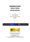
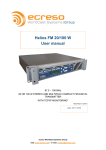
10.2 WOLF FRONT PANEL
N°
IMAGINE
DESCRIPTION
1
Display for:
“LOCAL CODER AUDIO MEASUREMENT”
2
Display for:
“MPX & RDS MEASUREMENT”
3
Display for:
“BACKUP SOURCE STATUS”
4
Display for:
“MPX & RDS MEASUREMENT”
Axel Technology |
15
5
Display for:
“INFO & ALARMS”
6
Display for:
“RDS DECODERS”
7
Monitor module with
7. Headphone socket for monitor - 6.3 mm
jack
8
8.
Output volume dial
9
Module for:
9. Listening audio selection
10
10. Transmitter selection
11
Selection:
LOCAL CODER + CHANGEOVER
Axel Technology |
16
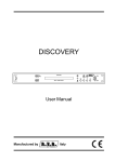
10.3 WOLF REAR PANEL
N°
1
FIGURE
DESCRIPTION
Label with device model and serial number
Power supply + fuse unit
2
3
RS232-1
RS-232 serial port n. 1. For Wolf device control
and monitoring and firmware upgrades
4
RS232-2
RS-232 serial port n.2. For Wolf device control
and monitoring
5
Ethernet
Ethernet port for connection to RJ-45
6
RS232-3
RS-232 serial port n. 3.
7
Vacancy for future implementations
Axel Technology |
17
8
Analog Audio Monitor Output
Analog audio output for the monitor. This output is
available when you select the monitor from the
front panel, via the balanced line male XLR
connector.
9
Opto Relays Interface 2
Isolated opto relay interface for aux. services 2
(see technical appendix for specifications)
10
Opto Relays Interface 1
Isolated opto relay interface for aux. services 1
(see technical appendix for specifications)
11
Relays
Relay interface (see appendix)
12
Digital audio I/O
AES/EBU Digital Audio Input and Output
13
BB MPX Reserve
Connection socket for MPX Breakout Box
14
MPX-2
Secondary MPX input (Backup)
15
MPX-1
Primary MPX input (Main)
16
MPX-0
MPX input from Local Coder (MPX0)
17
RF MONITOR
MONITOR RF input from Transmitter Test RF
18
BB Analog Reserve
Breakout box for analog Backup inputs
19
Analog audio I/O
Socket for Analog Inputs and Outputs
20
Air intake slits Fans inside the WOLF ensure
forced air circulation
Axel Technology |
18
WOLF CONNECTIONS (BREAKOUT BOXES)
11 WOLF CONNECTIONS (BREAKOUT BOXES)
To facilitate connections to and from Wolf, there are two different optional connection boxes available that simplify
connections. Thanks to these expansion panels, the connections can be brought to the front or rear of the rack,
depending on the technical requirements of the installation in question.
The Wolf handles analog and digital signals. More specifically, there are two different Breakout Boxes available, a
digital-only version (WLF-BBD) and a hybrid version, featuring inputs and outputs for analogue and mpx signals (WLFBBAM)
In the figure below, showing the Wolf Digital Breakout Box (WLF-BBD, there are two separate inputs (IN C and IN D) and
the relative outputs (OUT C and OUT D), in addition to the further outputs (OUT 1, OUT 2, OUT 3, OUT 4). These
outputs can be fully configured as required; the default jumper settings inside the Breakout Box are such that these
always reproduce OUTPUT C. All inputs and outputs are transformer de-coupled, with a characteristic impedance of 110
ohms.
In addition to the individual in/out connections, the BB also allows the device to have active independent service outputs
assignable to inputs/outputs. This is to facilitate installation. For the Breakout Box connection details and operating
parameters, please refer to the Technical Appendix at the end of the manual.
The figure below shows the Wolf Analog and MPX Breakout Box (WLF-BBAM).
Axel Technology |
19
WHAT IS THE WOLF NETWORK AND WHAT IS IT FOR?
12 WHAT IS THE WOLF NETWORK AND WHAT IS IT FOR?
The WOLF is a powerful, multi-functional FM station monitor . The device is designed to monitor audio signals, including
analog signals, digital signals, and MPX signals (with or without RDS), as well as free air signals, in the FM bandwidth
(87.5 - 108.0 MHz). The results of the measurements, whether performed on audio signals, MPX signals or on free air
signals, are directly accessible as HTML pages, using the built-in Web Server, or the dedicated PC monitoring software.
The results of the measurements carried out can also be compared with a grid of preset values, with the generation of
appropriate alarms in the event of out-of-range values. The Wolf supports the following protocols: UECP , SNMP, HTTP
and TFTP.
13 THE MAIN CONCEPT OF THE WOLF NETWORK DEVICE
The ways in which to connect the Wolf are many and varied. They differ depending on the needs of the broadcasters
using the device on their network. The versatility and, above all, the number of functions, operations, and facilities of this
equipment mean it can be put to a wide range of uses. One of the fundamental concepts of the Wolf, one of its most
conventional intended uses and - above all - one of the functions for which the device was conceived, is the ability to
manage its powerful internal changeover function, according to the precise meter featured. The Wolf‟s internal
changeover function allows the device to broadcast the „best‟ audio source, according to the reference parameters
configured internally.
14 AUTOMATIC MODE
In automatic mode, the Wolf automatically runs a series of pre-set measurements on audio signals and MPX, RDS and
antenna signals, and records the results in its log file. The machine can also compare the measurements against
reference values or ranges (called Thresholds) preset by the operator, or other reference data. This mode is generally
the standard operating mode. In this mode you cannot change any system configuration parameter. When the Wolf is
set to 'Auto' or is carrying out on-line measurements, other measurements are carried out at the same time, including:
Pilot Level, RDS level, peak deviation and power (as required by standard ITU-R BS412) on the two signals marked
MPX-1 and MPX-2. Depending on the how the device is configured, these will correspond to either the external Base
Bandwidth MPX-1 and MPX-2 inputs, the built-in tuner output, or the output of any external tuner that may be in use.
One RDS decoder stage, meanwhile, can be applied either to one of the two signals MPX-1 or MPX-2 or directly to the
signal outputted by the built-in tuner or the external tuner.
In addition, the Wolf decoder features a built-in digital stereo decoder which can also be applied to the internal MPX-1 or
MPX-2 signal. The output of the stereo decoder is measured using an RMS meter. The Wolf also measures stereo audio
input signals, both analogue and digital. The measurements concern the instantaneous peak level or the average peak
levels over a given period and also the instantaneous RMS level or the average level over a given period.
15 MANUAL MODE
When in manual mode, the parameters can be altered, but the device‟s automatic measuring and monitoring operations
will be suspended. In manual mode, a measurement can effectively be selected and the results viewed using the device
as a normal workbench tool.
The Wolf acts as a peak meter and an RMS meter (both stereo), which can be applied to either analog or
digital audio signals, as well as external MPX-1 and MPX-2 signals, whether at the output of the tuners or
of the MPX stereo decoder, which can, in turn, be applied to various signals. When the signal measured is
a mono signal (as in the case of an MPX), a 'Mono to Stereo' conversion module is automatically added to
the chain, to standardise it with the measurement of stereo audio signals. Note that the type of
measurement to be carried out, i.e. the pilot level, the pilot distortion, the RDS level, etc. is set via the
particular filter selected manually from those available in the filter selection menu page. All measurements
are always expressed as dBr (dB relative) and refer to the reference level selected for each input via the
Reference menu (see the Reference stages applied to each input, which actually represent the Fixed gain value
applied to that particular input). The Web Server screen page shows the Manual control settings.
16 LOCAL/REMOTE MODE
When it is in local mode, the Wolf does not accept operating commands from remote devices. All UECP / SNMP / HTTP
activation commands are therefore masked graphically via the software. TFTP commands are always accepted, as they
are considered globally configured macro-operations. In this mode it is assumed that the local operator has total control
of the device. In remote mode (normal operating condition), all commands are accepted, with all the complications for an
operator inherent to shared parameters in the event of local navigation.
Axel Technology |
20
HOW TO CONNECT THE WOLF
17 HOW TO CONNECT THE WOLF
Listed below are the maximum number of inputs and outputs available on the Wolf:
-
Balanced Stereo Analog Audio Input 1 (Analog- 1)
-
Balanced Stereo Analog Audio Input 2 (Analog- 2)
-
AES3/EBU Digital Audio Input 1 (Digital- 1)
-
AES3/EBU Digital Audio Input 2 (Digital- 2)
-
Multiplex Input 1 (MPX- 1)
-
Multiplex Input 2 (MPX- 2)
-
Local Coder Multiplex Input 0 (MPX- 0)
-
MONITOR RF input
Axel Technology |
21
CONTROL, MANAGEMENT, AND MONITORING SOFTWARE
18 CONTROL, MANAGEMENT, AND MONITORING SOFTWARE
This section explains how to install and configure the coordinating control, management, and monitoring software
assigned to the Wolf device. The products and applications currently available for both the Wolf Master and the Wolf are
listed below. For installation of the applications and compatibility with various operating systems (O.S.) and
configurations, please see the Appendices at the end of this manual:
-
Axel Wolf Target Address Manager
Axel Wolf Network Remoter
Axel Wolf Manager.
18.1 OVERVIEW OF AXEL WOLF ADDRESS MANAGER
The coordinating Axel Wolf Address Manager application is assigned to the Wolf device and, after its installation, it is
used to set the Wolf device start parameters. An RS-232 (COM) port is used for first and subsequent connections. The
parameters that can be set using this application are outlined below:
-
The communication port between the Workstation and the Wolf Network device
The UECP operating mode, which can vary between UECP (Standard) or UECP Extended
The Site List and the Encoder List in the event of use in UECP Standard or the ID List and the Group List in
the event of UECP Extended
The Local IP Address, the Local Subnet Mask, the Local Gateway and the Local Port for the Local Connection
via TCP/IP
The Remote IP Address, the Remote Subnet Mask, the Remote Gateway, and the Remote Port for the Remote
Connection via TCP/IP
The "NTP IP" address to configure the Network Time Protocol and its Port (NTP Port)
Extended Port configuration
Axel Technology |
22
CONTROL, MANAGEMENT, AND MONITORING SOFTWARE
18.2 OVERVIEW OF AXEL WOLF NETWORK REMOTER
After setting the various connection parameters (IP address, phone numbers, or serial ports) using Wolf Address
Manager, you can access the Wolf device via Wolf Remoter Network.
You can then connect to the device in a number of ways, such as:
Serial line (RS232)
GSM or PSTN modem and
TCP/IP. Once connected, this application enables you to ….
TFTP
Once inside the Wolf Network, you can perform any of the various operations outlined roughly below:
Check the status of the Wolf Network, to see at a glance whether or not there are any errors.
Set the time and date (both local and UTC) of the Wolf Network device (Clock and Editor)
Access Wolf Editor (Wolf Editor)
Read the measurements carried out automatically by the Wolf Network (Automatic Measures)
Read the log of the measurements performed by the Wolf Network (Measure DB)
Read the off-line measurements carried out by the Wolf Network (Offline Data)
Some examples can be seen in the figures below
Axel Technology |
23
CONTROL, MANAGEMENT, AND MONITORING SOFTWARE
18.3 OVERVIEW OF AXEL WOLF MANAGER
Wolf Manager is designed and structured to provide a global view of the Wolf Network device as graphically as possible.
This application can be considered a "lighter" version of Axel Ranger, which is a much more intricate device monitoring
and management program. For more information on the Axel Ranger application, visit the website
www.axeltechnology.com or ring Axel Technology, using the phone numbers on the front page.
Wolf Manager is an application that is installed on platforms like Windows and allows the user to read and manage the
measurements performed by the Wolf Network. Again, for installation methods and compatibility, please see the
appendix at the end of the manual. Wolf Manager provides a graphic display of all the Wolf Network device‟s alarms,
statuses, readings and log files:
-
Device Info
Changeover Status
Audio OnAir
Alarms
Measures
Changeover
Monitor
Primary Audio
MPX-1
MPX-2
MPX-0
FM Tuner
Monitor RDS
General Data
Log Files
The following pages of this manual contain more detailed explanations of how the three applications can be configured.
Axel Technology |
24
CONTROL, MANAGEMENT, AND MONITORING SOFTWARE
18.4 USING AXEL WOLF ADDRESS MANAGER FOR THE FIRST TIME
As explained in the previous section, Wolf Address Manager "guides" the machine through UECP and/or IP and SNMP
and NTP encoding identifiers. First of all, you have to install the applications supplied with the Wolf device on your PC.
They are contained on a CD-ROM and the installation procedure is outlined below:
1. Insert the CD-ROM into your PC.
2.
Run the auto-install file "Setup.exe”
3.
Connect the Wolf Network device to the power supply and switch it on. This is the screen that
appears when you run setup.exe. The file may also be obtained directly from Axel Technology
s.r.l. or another retailer, in which case it may be provided in a . rar or other compressed format.
In this case, you should decompress the file and save it on your PC's system disk before
carrying out the installation.
4.
Once you have launched Setup.exe and obtained the
necessary information from the operating system, the
following screen will appear. Press the NEXT button to
proceed with the installation of the executable contents for
the Wolf Network.
5.
When the NEXT button is pressed, the Customer Information
window appears, where you will have to set the "Username"
and "Organization" and whether or not the application needs
to be installed for and used by a single user or "all users"
6.
Clicking NEXT takes you on to the following step, which is
the selection of the application installation path. Generally
speaking, you should adopt the standard pathway proposed
by the operating system. However, the target location can
be altered by clicking Change in the right-hand central
section of the page.
7.
When the Next button is pressed again, a quick summary of
the installation settings is displayed or a "Ready to Install
Axel Technology |
25
CONTROL, MANAGEMENT, AND MONITORING SOFTWARE
the Program" message, while clicking again takes you to the actual phase in which installation of the
applications within the operating system takes place.
A blue bar shows installation progress.
8.
After installation - and once the various installation
processes have been checked - the program will display the
following message: "InstallShield Wizard Complete"
9.
At this point, two new icons will have appeared on your
computer's desktop :
- Axel Wolf Address Manager vX.X.X
- Axel Wolf Network Remoter vx.x.x
You can now connect the Wolf Network to your PC and use
the services offered by the various applications to start
using the Wolf Network device.
Axel Technology |
26
CONTROL, MANAGEMENT, AND MONITORING SOFTWARE
18.5 CONFIGURING THE WOLF
1.
Connect the 9-pole Male/Female Pin-to-Pin cable (for connection to the Wolf device) to the COM(x) port of your
computer. This cable comes supplied with the Wolf Network device and can be found inside the box.
2.
Connect the aforesaid cable to the Wolf device via the RS232-1 port, or the Wolf COM number 1 port, which is
also the only one enabled for operation of Wolf Address Manager.
3.
Launch the previously installed Wolf Address Manager program using the icon on your PC‟s desktop or another
link.
4.
Press the Connect to Target button in the top central section
of the screen.
5.
Once the Connect to Target button has been pressed, the data stored inside the device will appear. More
specifically, the figure below shows a Wolf Network device with some of the data programmed. To edit the
default manufacturer‟s settings configured by Axel
Technology, simply position the cursor on the field and
change the data. Once you have changed the settings to
the desired values, enter the data in the Wolf Network
device by clicking the Send Data button in the bottom righthand corner of the
software panel.
6.
Once the data has been sent successfully to the device, the Send Data button will
go back to its original grey colour. To read the settings stored in the device, press
the "Reload Data" button in the central section of the screen. This operation is
used to recall the settings stored in the Wolf Network.
7.
Once these settings have been configured you can use the Axel Wolf Network Remoter application for device
management. See the next section.
N.B: With regards to speed on the RS232-1 port, the factory default setting is 38,400 bps, and Wolf Address
Manager has this at its default setting after installation on your computer. This setting can also be edited, but
since this is the preferred port for communication and the Wolf Network device configuration, we strongly advise
you NOT to alter this port value. For port speed editing, see the appendix at the end of the manual.
Axel Technology |
27
USING WOLF REMOTER FOR THE FIRST TIME
19 USING WOLF REMOTER FOR THE FIRST TIME
As explained in the previous section, the Wolf Network Remoter application is the software that allows access to the
device and editing of the operating parameters. The following connection procedures are currently available:
1.
2.
3.
4.
LOCAL RS 232
MODEM
TCP/IP
TFTP (under development)
1.
First of all, start up Wolf Network Remoter by launching the executable file from the location in which you installed it
(e.g. Desktop)
2.
The following window will appear:
3.
LOCAL RS 232 mode
At the moment, the RS 232 LOCAL mode is the simplest, as it
involves the use of a single pin-to-pin serial cable connected to a
single control PC. To do this, select Local RS232 in the
Communication Channel panel, as seen in the figure.
After you do this, select the Serial Port you intend to use in your
PC and its port speed. These two parameters can be found in the
Serial
Parameters
panel,
beside
the
Communication Channel. Once you have set
the correct values to access the Wolf Network,
press the Connect button.
If the connection is successful, the Messages panel will show the message “Connection to target successfully
established" and will also feature some of the data of the Wolf Network device to which you are connected, such as the
target type, the firmware version, and the firmware code. This means you are properly connected with the Wolf Network.
Axel Technology |
28
USING WOLF REMOTER FOR THE FIRST TIME
19.1 DIRECT LINK VIA MODEM UPLINK
It is possible to connect a PC and a remotely installed Wolf Network via a dial-up
modem connection. Each time the connection is made via two dial-up modems, select
'MODEM' in the communication channel configuration windows (ComChannel). The
connection mode ('Connection mode') will be automatically set to 'bidirectional':
See the next section of this manual for the physical connection between the modem and the
Wolf Network, at the remote end (serial port 1 of the Wolf Network must be used for this
purpose).
Using Wolf Remoter Network, set the serial port used to connect to the modem and the
associated connection speed (which is usually 38400 baud for POTS/PSTN modems and
9600 baud for GSM modems). You will also need to enter a modem initialization string
SERIAL PORT
Select the PC serial port to use for the connection (from 1 to 255). In the case of a USB modem,
check that the 'virtual' serial port is selected automatically by the PC.
SERIAL
SPEED
Set the maximum transmission speed for the selected PC port. By default, the Remoter will display
the maximum value (38400 Baud).
The communication transmission speed set in the control PC’s software must MATCH the
transmission speed of the modem connected.
INITIALIZ.
STRING
Enter the AT initialization string here. The BSN offers two string options. The shortest
(at&f&k0&c0&r1s2=255) is usually suitable for internal PCI modems,
(at&f0&k0&c0&s0&r1s2=255) is usually suitable for external modems.
TEL. NUMBER
while
the
longest
Enter the number to dial here (including country code, area code, etc.).
Click OK to confirm, or ESC to quit without saving.
Axel Technology |
29
USING WOLF REMOTER FOR THE FIRST TIME
19.2 CONNECTION TO A DIAL-UP MODEM
Whenever remote control via a dial-up modem is required, connect the modem to the serial port 1 on the back of the unit.
Remember to check the configuration of port 1. Its speed must be set to:
- 38400 baud for a POTS dial-up modem
- 9600 baud for a GSM modem.
A 'crossover' CABLE (NULL MODEM) is required to for the modem connection. The table below shows the wiring
diagram for the cable in both cases in which the modem has 9-pin or 25-pin Sub-D female connectors.
Remember also that:
Pin
Pin
Pin
Pin
On a 25-pin plug, connect pins 6 and 8.
On a 9-pin plug, connect pins 1 and 6.
WOLF end (Male Sub-D9)
2
3
4
5
Modem end (M Sub-D 9p)
3
2
6 and 1
5
Modem end (M Sub-D 25p)
2
3
6 and 8
7
Axel Technology |
30
USING WOLF REMOTER FOR THE FIRST TIME
The receiver modem (the one connected to the Shark serial port) must have at least the following settings (modem
commands are between brackets and refer to the most common modem models):
- IGNORE CDs (the standard command is &C0)
- IGNORE RTS (&R1)
- IGNORE DTR (&D0)
- Disable TX Flow Control (&H0)
- Disable RX Flow Control (&I0)
- Disable Data Compression (&K0)
You will also need to set registers S0 and S2 as follows:
-
S0=2
-
S2=255
The S0 register is the number of rings before Auto Answer. It is used to set the number of rings required before the
modem automatically answers a call. Range: 0-255 rings). Setting this register to zero disables auto answer mode. S0 =
n, where n is the number of rings. We recommend you set S0 = 2
The S2 register (Escape Code Character) specifies the ASCII value of the character used in the escape code (The
escape code is the escape character entered three times in a row.) When the modem is in connected status and
receives the escape code, the modem enters the command status. Normally, setting the S2 register to 128 or above
disables the escape code character. We recommend you set S2 = 255
You will need to load these settings in the modem memory, so that they are loaded immediately at modem start-up.
Please refer to the modem's user manual for more information.
19.3 CONNECTION VIA TCP/IP (NETWORK)
Make sure the Wolf already has a valid TCP/IP subnet mask and an IP port number (see next section for more
information). Select 'TCP/IP' in the communication channel configuration windows (ComChannel). A screen summarising
the current TCP / IP connection data will appear :
To enter the actual Wolf Network IP address and IP port to connect to, click on [EDIT TCP / IP Database]. The
Configuration Editor program will open. For Editor use, please see the relative section.
Click on the
button. The Configuration Editor screen will load the data base of the existing TCP/IP connections
and list them.
More in detail, in the [GROUP_START] section, the editor allows you to enter a 'mnemonic' name for the group to which
you are connecting, plus a name for the specific unit within the group, its IP address and the port associated with it.
;----------------------- Example ------------------------;
;[GROUP_START]
;
; GROUP_NAME="East-Coast Bridge DPL-01"
;
; WOLF_1="Split 1 - Middle Town", 128.198.076.030 , 2060
; WOLF_2="Split 2 - Route 66", 128.198.035.121 , 3007
; WOLF_3="Split 3 - San Andreas", 128.198.163.002 , 12034
; WOLF_4="Split 4 - Beverly Hills", 128.198.004.100 , 7771
;
;[GROUP_END]
Axel Technology |
31
USING WOLF REMOTER FOR THE FIRST TIME
EXAMPLE
For example, if you're connecting to three units, two from one group and one from another:
A Wolf with the address 128,198,076,030, assigned port 2060 and name Split 1- Middle Town belonging to the group
"EAST-Coast Bridge DPL-01"
A Wolf with the address 128.198.035.121, assigned port 3007 and name Split 2 - Route 66 belonging to the group
"EAST-Coast Bridge DPL-01"
And so on until all the devices you want the Wolf Network to control have been entered.
You will have to uncheck the
box and edit the lines
If you only want to control a single Wolf Network device, and this device has been entered into your LAN network,
proceed as follows:
1.Enter the Group_Name as a mnemonic name that refers to the device (in the example: Wolf Network-1)
2.Enter the name of the device as the name in WOLF_1 (in the example : Wolf Network -1)
3. Enter the target IP of the Wolf Network previously assigned with Wolf Address Manager and the port.
4. If not used, you can also delete the other Wolf connection parameters that do not exist in your network.
5.Once the IP address and relative ports have been entered, save them by clicking and accepting the change of data
base.
6.Close the Configuration Editor by clicking on
and return to the ComChannel settings .
;[GROUP_START]
;
; GROUP_NAME="Wolf Network-1"
;
; WOLF_1="Wolf Network-1", 192.168.099.065 , 1327
;
;[GROUP_END]
Click OK to confirm, or ESC to quit without saving.
Axel Technology |
32
/ WOLF NETWORK CONFIGURATION
20 WOLF NETWORK CONFIGURATION
Once the connection has been established between the PC
and the Wolf Network device, various items of connection data
will appear on the communications panel on the right. This
message box also shows that the connection has been
successfully established.
In the lower section of the screen of the Wolf Target Remoter control software, there is also an additional horizontal bar
that can be used to perform certain operations (1) (Connections - Clock and Editor - Automatic Measures - Measure DB Offline Data), while the Disconnect and Exit (2) buttons appear in the middle section. Disconnect is used to disconnect
the device from your PC, while Exit is used to quit the program.
Axel Technology |
33
CLOCK AND EDITOR
21 CLOCK AND EDITOR
By clicking Clock and Editor you can access the most important part of the device, the part where you can set the
minimum and maximum setpoints and the Wolf Network trigger thresholds. The Clock and Editor submenu window that
appears is divided into two and features the Wolf Configuration Editor on the left-hand side and the "Wolf Internal Clock
Synchronizer" on the right, which shows not only the current time taken from the PC but also the UTC (Universal Time
Code) and the Local Time Offset according to the country of use and the offset from GMT. When you press the
Synchronize button, the program asks whether you want to the enter the time taken by the Wolf Network from the PC
where you are configuring the device.
If you press Access to Wolf Editor you will enter the Wolf Network device and so will be able to configure the machine to
work in your network. Once this has been pressed, a window opens where you can send commands to the Wolf
Network device. Clicking the
IMPORT button allows you to view the data inside the Wolf Network device
and configure the setpoints and operating values.
Axel Technology |
34
WOLF NETWORK CONFIGURATION IMPORT / EXPORT FILE
22 WOLF NETWORK CONFIGURATION IMPORT / EXPORT FILE
In this part of the control software, you will see various parameters. The first section, shown below, specifies the file
name, author, date/time of changes and any notes that may be included for the device in question.
;****************************************************************************************
;* WOLF NETWORK CONFIGURATION IMPORT/EXPORT FILE
;*
;* FILE : untitled.tcf
;*
;* AUTHOR:
;*
;* DATE : 08/08/2011
;* TIME : 16:10:30
;*
;* NOTES :
;*
;****************************************************************************************
The lower section, meanwhile, shows the Wolf Network operating values (the settable values are discussed in the next
section):
N°
Parameter name/command
[GENERAL_SETTINGS]
01
02
TARGET_MODEL=Wolf_Slave
FIRMWARE_VERSION=2.0
03
TARGET_NAME="WF3-Axel"
04
EXTENDED_TARGET_NAME="WF3-Sede Axel"
05
USER_NAME=""
06
PASSWORD=""
07
WEB_PASSWORD=""
08
Description
Notes
Menu name and description
Name of connected device
Firmware release installed on
“TARGET_MODEL”
Name of TARGET_MODEL device which will
appear in the software and on the front panel
(INFO & ALARMS) of the Wolf Network
Full name of TARGET_MODEL device which
will appear in the software and on the front
panel (INFO & ALARMS) of the Wolf Network
Non-editable field
User name which will be requested when
accessing the Wolf Network device via Remoter
Password which will be requested when
accessing the Wolf Network device via Remoter
Password which will be requested when
accessing the Wolf Network device via
webpage.
If the field is empty, this is not
required
If the field is empty, this is not
required
If the field is empty, this is not
required
KEYBOARD_LOCK=Unlocked
This parameter allows you to lock the Wolf
Network device‟s front keypad.
When locked, the keypad cannot be
used.
09
SNMP_PRIVATE_ACCESS_PASSWORD="private"
Password for writing via SNMP protocol (default
setting is "private”)
10
SERIALS_SPEED=38400_Baud
11
12
13
14
SERIAL_1_MODE=Bidirectional
SERIAL_2_MODE=Bidirectional
SERIAL_3_MODE=Uecp
ANALOGIC_OUT_LEVEL=+3.5dB
Speed setting for all three serial ports. This
parameter is unique.
RS232-1 port connection mode
Rs232-2 port connection mode
Rs232-3 port connection mode
Analog Output Level Setting
15
16
17
DIGITAL_INTERFACE=On
DIGITAL_OUT_LEVEL=-21.7dBFs
DIGITAL_OUT_RATE=44.1KHz
AES3/EBU output enable
Digital output level
Digital output sample rate
18
MASK_ALL_ALARMS=Off
This enables or disables alarm reporting by the
Wolf device
19
WEB_REFRESH_SPEED=Normal
Wolf Web page refresh speed setting
20
21
NETWORK_POSITION=0
NETWORK_POSITION_TIME=0SEC
22
PILOT_PROT_MEASURE=On
Default setting is 38400_Baud
Monodirectional and Bidirectional
Monodirectional and Bidirectional
Pilot Protection measurement enable
Axel Technology |
35
WOLF NETWORK CONFIGURATION IMPORT / EXPORT FILE
23
RDS_UECP_PROPAGATION=On
24
25
26
AUTO_TIME_SYNC=Off
EXTENDED_TCPIP_PORT_SEL=Serial_2
NTP_LOCAL_TIME_OFFSET=+0:00
Dissemination of UECP data from Wolf device
and retransmission thereof, filtered or not, to
other UECP compatible devices
See Target Propagation Settings
NTP service offset
[END_GENERAL_SETTINGS]
[TARGET_PROPAGATION_SETTINGS]
27
DEST_ENCODER_ADDRESS=0
28
DEST_SITE_ADDRESS=0
Destination Encoder Address for UECP packets
received by Wolf
Destination Site Address for UECP packets
received by Wolf
[END_TARGET_PROPAGATION_SETTINGS]
[MEASURES_SETTINGS]
29
AUDIO_REFERENCE=+3.5dBu
30
DIGITAL_REFERENCE=-21.7dBFs
Analog Audio Input Setpoint for both Analog-1
and Analog-2
Digital Audio Input Setpoint
31
32
33
MPX_0_REFERENCE=+0.0dBu
MPX_1_REFERENCE=+0.0dBu
MPX_2_REFERENCE=+0.0dBu
Local CoderMPX-0 input setpoint
MPX-1 input setpoint
MPX-2 input setpoint
34
DECODER_DEEMPHASIS=50us
De-emphasis value setting for decoder MPX
Possible values: 0, 50,75 µS
DECODER_PILOT_RDS_COMPENSATION=1.15dB
This parameter represents a correction factor
that is entered to offset the loss of audio level
generated on the stereo audio signal, due to
the deviation lost because of the Stereo Pilot
injection and the Carrier with RDS data
modulation.
Depending on the Pilot level and the RDS level
used, this parameter allows you to bring the
audio
level
meter
to
zero.
With the same deviation, the audio
level changes according to the
deviation lost because of the RDS
and the Pilot, and this parameter is
used to realign the measurement to
offset this loss. The default value is
the compensation required for a 21dB pilot and a -28dB RDS.
35
[END_MEASURES_SETTINGS]
[MASTER_IDENTIFICATION]
36
37
NATIONAL_MASTER=0
OFFLINE_MASTER_ID=0
[END_MASTER_IDENTIFICATION]
[AUTOMATIC_MODE_PRESET]
38
AUTO_AUDIO_MAIN_SEL=Decoder_Mpx1
39
40
41
42
AUTO_AUDIO_BACKUP_SRC1_SEL=Decoder_Mpx2
AUTO_AUDIO_BACKUP_SRC2_SEL=Digital_2
AUTO_AUDIO_BACKUP_SRC3_SEL=Digital_1
AUTO_AUDIO_BACKUP_SRC4_SEL=Off
This section is for changeover operation, with
the relative exchange ranking.
Selection of the Main Source for control and
broadcasting in Automatic
FIRST Back-up broadcasting source
SECOND Back-up broadcasting source
THIRD Back-up broadcasting source
FOURTH Back-up broadcasting source
43
ALARM_AUDIO_SILENCE_THR=-40.0dB
This parameter sets the audio threshold value
below which the sound is considered silence
44
ALARM_AUDIO_SILENCE_TIME=5sec
This parameter specifies how long (in seconds)
before the audio level below the
"ALARM_AUDIO_SILENCE_THR =" value
should be considered silence, in which case an
This parameter (43) is strictly linked
to parameter 44
Axel Technology |
36
WOLF NETWORK CONFIGURATION IMPORT / EXPORT FILE
alarm will be generated.
45
ALARM_AUDIO_PEAK_THR_LOW=No_Inf_Limit
46
ALARM_AUDIO_PEAK_THR_HIGH=+3.0dB
47
ALARM_AUDIO_RMS_THR_LOW=No_Inf_Limit
48
ALARM_AUDIO_RMS_THR_HIGH=-3.0dB
49
50
ALARM_AUDIO_AVG_RMS_THR_LOW=No_Inf_Limi
t
ALARM_AUDIO_AVG_RMS_THR_HIGH=-3.0dB
51
52
ALARM_AUDIO_AVG_PEAK_THR_LOW=No_Inf_Lim
it
ALARM_AUDIO_AVG_PEAK_THR_HIGH=+3.0dB
This parameter sets the Audio Peak
measurement value below which the parameter
becomes invalid and an alarm is generated.
This parameter sets the Audio Peak
measurement value above which the parameter
becomes invalid and an alarm is generated.
No_Inf_Limit = control disabled
(see protocol)
This parameter sets the Audio RMS
measurement value below which the parameter
becomes invalid and an alarm is generated.
This parameter sets the Audio RMS
measurement value above which the parameter
becomes invalid and an alarm is generated.
No_Inf_Limit = control
disabled
(see protocol)
This parameter sets the Audio RMS Average
measurement value below which the parameter
becomes invalid and an alarm is generated.
This parameter sets the Audio RMS Average
measurement value above which the parameter
becomes invalid and an alarm is generated.
No_Inf_Limit = control
disabled
(see protocol)
This parameter sets the (average) Audio Peak
measurement value below which the parameter
becomes invalid and an alarm is generated.
This parameter sets the (average) Audio Peak
measurement value above which the parameter
becomes invalid and an alarm is generated.
No_Inf_Limit = control
disabled
(see protocol)
53
ALARM_MPX_1_PILOT_THR_LOW=-23.5dB
54
ALARM_MPX_1_PILOT_THR_HIGH=-21.5dB
55
ALARM_MPX_1_PILOT_PROT_THR=-45.0dB
This parameter sets the pilot protection
measurement value, i.e. the purity (presence or
absence of spurious and harmonic emissions,
disturbance…) around the 19Hz frequency or
the stereophonic pilot. The measurement is
taken at the MPX-1 input. If the measurement is
above the value set, an alarm is generated.
56
ALARM_MPX_1_RDS_THR_LOW=-28.5dB
57
ALARM_MPX_1_RDS_THR_HIGH=-25.5dB
This parameter sets the RDS data carrier (57
Hz) measurement value at the MPX-1 input. If
the measurement is below the value set, an
alarm is generated.
This parameter sets the RDS data carrier (57
Hz) measurement value at the MPX-1 input. If
the measurement is below the value set, an
alarm is generated.
58
ALARM_MPX_1_PEAK_DEV_THR_LOW=No_Inf_Lim
it
59
ALARM_MPX_1_PEAK_DEV_THR_HIGH=90KHz
60
ALARM_MPX_1_ITUB412_THR_LOW=No_Inf_Limi
t
61
ALARM_MPX_1_ITUB412_THR_HIGH=No_Sup_Lim
it
No_Sup_Limit = control
disabled
(see protocol)
No_Sup_Limit = control
disabled
(see protocol)
No_Sup_Limit = control
disabled
(see protocol)
No_Sup_Limit = control
disabled
(see protocol)
This parameter sets the stereophonic pilot
carrier (19Hz) measurement value at the MPX1 input. If the measurement is below the value
set, an alarm is generated.
This parameter sets the stereophonic pilot
carrier (19Hz) measurement value at the MPX1 input. If the measurement is below the value
set, an alarm is generated.
See the section on Pilot Protection
This parameter sets the peak deviation of the
MPX signal at the MPX-1 input. If the
measurement is below the value set, an alarm
is generated.
This parameter sets the peak deviation of the
MPX signal at the MPX-1 input. If the
measurement is above the value set, an alarm
is generated.
This parameter sets the MPX Power (19Hz)
measurement
value
(expressed
as
recommendations ITU BS 412) at the MPX-1
input. If the measurement is below the value
set, an alarm is generated.
This parameter sets the MPX Power (19Hz)
measurement
value
(expressed
as
recommendations ITU BS 412) at the MPX-1
input. If the measurement is above the value
Axel Technology |
37
WOLF NETWORK CONFIGURATION IMPORT / EXPORT FILE
set, an alarm is generated.
62
ALARM_MPX_1_DEC_AUDIO_THR_LOW=No_Inf_Li
mit
63
64
ALARM_MPX_1_DEC_AUDIO_THR_HIGH=+3.0dB
ALARM_MPX_1_DEC_AUDIO_SILENCE_THR=40.0dB
65
ALARM_MPX_1_DEC_AUDIO_SILENCE_TIME=5sec
This parameter sets the DECoded audio
measurement value at the MPX-1 input. If the
measurement is below the value set, an alarm
is generated.
This parameter sets the DECoded audio
measurement value at the MPX-1 input. If the
measurement is above the value set, an alarm
is generated.
This parameter sets the minimum audio
threshold value at the MPX-1 Decoder input
below which the sound is considered silence.
This parameter specifies how long (in seconds)
before an audio level at MPX-1 DECoder input
below the "ALARM_AUDIO_SILENCE_THR ="
value should be considered silence, in which
case an alarm will be generated.
66
ALARM_MPX_2_PILOT_THR_LOW=-23.5dB
67
ALARM_MPX_2_PILOT_THR_HIGH=-20.5dB
68
ALARM_MPX_2_PILOT_PROT_THR=-45.0dB
This parameter sets the pilot protection
measurement value, i.e. the purity (presence or
absence of spurious and harmonic emissions,
disturbance…) around the 19Hz frequency or
the stereophonic pilot. The measurement is
taken at the MPX-2 input. If the measurement is
above the value set, an alarm is generated.
69
ALARM_MPX_2_RDS_THR_LOW=-28.5dB
70
ALARM_MPX_2_RDS_THR_HIGH=-26.5dB
This parameter sets the RDS data carrier (57
Hz) measurement value at the MPX-2 input. If
the measurement is below the value set, an
alarm is generated.
This parameter sets the RDS data carrier (57
Hz) measurement value at the MPX-2 input. If
the measurement is below the value set, an
alarm is generated.
71
ALARM_MPX_2_PEAK_DEV_THR_LOW=No_Inf_Lim
it
72
ALARM_MPX_2_PEAK_DEV_THR_HIGH=90KHz
73
ALARM_MPX_2_ITUB412_THR_LOW=No_Inf_Limi
t
74
ALARM_MPX_2_ITUB412_THR_HIGH=No_Sup_Lim
it
75
ALARM_MPX_2_DEC_AUDIO_THR_LOW=No_Inf_Li
mit
76
ALARM_MPX_2_DEC_AUDIO_THR_HIGH=+3.0dB
No_Inf_Limit = control
disabled
(see protocol)
This parameter sets the stereophonic pilot
carrier (19Hz) measurement value at the MPX2 input. If the measurement is below the value
set, an alarm is generated.
This parameter sets the stereophonic pilot
carrier (19Hz) measurement value at the MPX2 input. If the measurement is below the value
set, an alarm is generated.
This parameter sets the Peak deviation of the
MPX signal at the MPX-2 input. If the
measurement is below the value set, an alarm
is generated.
This parameter sets the Peak deviation of the
MPX signal at the MPX-2 input. If the
measurement is above the value set, an alarm
is generated.
This parameter sets the MPX Power (19Hz)
measurement
value
(expressed
as
recommendations ITU BS 412) at the MPX-2
input. If the measurement is below the value
set, an alarm is generated.
This parameter sets the MPX Power (19Hz)
measurement
value
(expressed
as
recommendations ITU BS 412) at the MPX-2
input. If the measurement is above the value
set, an alarm is generated.
This parameter sets the DECoded audio
measurement value at the MPX-2 input. If the
measurement is below the value set, an alarm
is generated.
This parameter sets the DECoded audio
measurement value at the MPX-2 input. If the
measurement is above the value set, an alarm
is generated.
Axel Technology |
38
WOLF NETWORK CONFIGURATION IMPORT / EXPORT FILE
77
ALARM_MPX_2_DEC_AUDIO_SILENCE_THR=40.0dB
78
ALARM_MPX_2_DEC_AUDIO_SILENCE_TIME=5sec
This parameter sets the minimum audio
threshold value at the MPX-2 DECoder input
below which the sound is considered silence.
This parameter specifies how long (in seconds)
before an audio level at MPX-2 DECoder input
below the "ALARM_AUDIO_SILENCE_THR="
value should be considered silence, in which
case an alarm will be generated
79
ALARM_FM_MPX_PILOT_THR_LOW=-23.5dB
80
ALARM_FM_MPX_PILOT_THR_HIGH=-21.5dB
81
ALARM_FM_MPX_PILOT_PROT_THR=-35.0dB
This parameter sets the pilot protection
measurement value, i.e. the purity (presence or
absence of spurious and harmonic emissions,
disturbance…) around the 19Hz frequency or
the stereophonic pilot. The measurement is
taken at the FM input (Monitor-RF). If the
measurement is above the value set, an alarm
is generated.
82
ALARM_FM_MPX_RDS_THR_LOW=-28.5dB
This parameter sets the RDS data carrier (57
Hz) measurement value at the FM input
(Monitor-RF). If the measurement is below the
value set, an alarm is generated.
83
ALARM_FM_MPX_RDS_THR_HIGH=-26.5dB
This parameter sets the RDS data carrier 57
Hz) measurement value at the FM input
(Monitor-RF). If the measurement is above the
value set, an alarm is generated.
84
ALARM_FM_MPX_PEAK_DEV_THR_LOW=No_Inf_Li
mit
85
ALARM_FM_MPX_PEAK_DEV_THR_HIGH=90KHz
86
ALARM_FM_MPX_ITUB412_THR_LOW=No_Inf_Lim
it
87
ALARM_FM_MPX_ITUB412_THR_HIGH=No_Sup_Li
mit
88
ALARM_FM_MPX_DEC_AUDIO_PEAK_THR_LOW=No_
Inf_Limit
89
ALARM_FM_MPX_DEC_AUDIO_PEAK_THR_HIGH=+3
.0dB
90
ALARM_FM_MPX_DEC_AUDIO_PEAK_SILENCE_THR
=-40.0dB
91
ALARM_FM_MPX_DEC_AUDIO_PEAK_SILENCE_TIM
E=5sec
This parameter sets the stereophonic pilot
carrier (19Hz) measurement value at the FM
input (Monitor-RF). If the measurement is below
the value set, an alarm is generated.
This parameter sets the stereophonic pilot
carrier (19Hz) measurement value at the FM
input (Monitor-RF). If the measurement is
above the value set, an alarm is generated.
This parameter sets the Peak deviation of the
MPX signal at the FM input (Monitor-RF). If the
measurement is below the value set, an alarm
is generated.
This parameter sets the Peak deviation of the
MPX signal at the FM input (Monitor-RF). If the
measurement is above the value set, an alarm
is generated.
This parameter sets the MPX Power
measurement
value
(expressed
as
recommendations ITU BS 412) at the FM input
(Monitor-RF). If the measurement is below the
value set, an alarm is generated.
This parameter sets the MPX Power
measurement
value
(expressed
as
recommendations ITU BS 412) at the FM input
(Monitor-RF). If the measurement is above the
value set, an alarm is generated.
This parameter sets the Peak DECoded audio
measurement value at the FM input (MonitorRF). If the measurement is below the value set,
an alarm is generated.
This parameter sets the Peak DECoded audio
measurement value at the FM input (MonitorRF). If the measurement is above the value set,
an alarm is generated.
This parameter sets the minimum audio
threshold value at the FM DECoder input
(Monitor-RF) below which the sound is
considered silence.
This parameter specifies how long (in seconds)
before an audio level at FM DECoder input
(Monitor-RF)
below
the
"ALARM_AUDIO_SILENCE_THR=" value should
Axel Technology |
39
WOLF NETWORK CONFIGURATION IMPORT / EXPORT FILE
be considered silence, in which case an alarm
will be generated
92
ALARM_MPX_0_PILOT_THR_LOW=-23.5dB
93
ALARM_MPX_0_PILOT_THR_HIGH=-21.5dB
94
ALARM_MPX_0_PILOT_PROT_THR=-50.0dB
This parameter sets the pilot protection
measurement value, i.e. the purity (presence or
absence of spurious and harmonic emissions,
disturbance…) around the 19Hz frequency or
the stereophonic pilot. The measurement is
taken at the FM input (Monitor-RF). If the
measurement is above the value set, an alarm
is generated.
95
ALARM_MPX_0_RDS_THR_LOW=-28.5dB
96
ALARM_MPX_0_RDS_THR_HIGH=-26.5dB
This parameter sets the RDS data carrier (57
Hz) measurement value at the MPX-0 input. If
the measurement is below the value set, an
alarm is generated.
This parameter sets the RDS data carrier (57
Hz) measurement value at the MPX-0 input. If
the measurement is above the value set an
alarm is generated.
97
ALARM_MPX_0_PEAK_DEV_THR_LOW=No_Inf_Lim
it
98
99
ALARM_MPX_0_PEAK_DEV_THR_HIGH=90KHz
ALARM_MPX_0_ITUB412_THR_LOW=No_Inf_Limi
t
100
ALARM_MPX_0_ITUB412_THR_HIGH=No_Sup_Lim
it
101
ALARM_MPX_0_DEC_AUDIO_PEAK_THR_LOW=No_I
nf_Limit
102
ALARM_MPX_0_DEC_AUDIO_PEAK_THR_HIGH=+1.
0dB
103
ALARM_MPX_0_DEC_AUDIO_PEAK_SILENCE_THR=
-40.0dB
104
ALARM_MPX_0_DEC_AUDIO_PEAK_SILENCE_TIME
=5sec
This parameter sets the stereophonic pilot
carrier (19 Hz) measurement value at the MPX0 input. If the measurement is below the value
set, an alarm is generated.
This parameter sets the stereophonic pilot
carrier (19 Hz) measurement value at the MPX0 input. If the measurement is below the value
set, an alarm is generated.
This parameter sets the Peak deviation of the
MPX signal at the MPX-0 input. If the
measurement is below the value set an alarm is
generated.
This parameter sets the Peak deviation of the
MPX signal at the MPX-0 input. If the
measurement is above the value set, an alarm
is generated.
This parameter sets the MPX-0 Power (19 Hz)
measurement
value
(expressed
as
recommendations ITU BS 412) at the MPX-0
input. If the measurement is below the value
set, an alarm is generated.
This parameter sets the MPX-0 Power (19Hz)
measurement
value
(expressed
as
recommendations ITU BS 412) at the MPX-0
input. If the measurement is above the value
set, an alarm is generated.
This parameter sets the Peak DECoded audio
measurement value at the MPX-0 input. If the
measurement is below the value set, an alarm
is generated.
This parameter sets the Peak DECoded audio
measurement value at the MPX-0 input. If the
measurement is above the value set an alarm
is generated.
This parameter sets the minimum audio
threshold value at the MPX-0 DECoder input
below which the sound is considered silence.
This parameter specifies how long (in seconds)
before an audio level at MPX-0 DECoder input
below the "ALARM_AUDIO_SILENCE_THR="
value should be considered silence, in which
case an alarm will be generated.
105
AUTO_RDS_DECODER_SOURCE_SEL=Mpx1
This parameter specifies which MPX source
should be connected to the RDS decoder in
order to view, control and monitor RDS data.
106
AUTO_TUNER_FREQUENCY=100.80MHz
In this parameter you can set the tuning
Axel Technology |
40
WOLF NETWORK CONFIGURATION IMPORT / EXPORT FILE
frequency of the internal FM tuner (MonitorRF).
[END_AUTOMATIC_MODE_PRESET]
[RDS_MASK_SETTINGS]
107
108
109
110
111
112
113
114
TRAFFIC_ANNOUNCEMENT=On
TRAFFIC_PROGRAM=On
ALTERNATIVE_FREQUENCIES=On
MUSIC_SPEECH=Music
DECODER_IDENTIFICATION=Stereo_Static_Pt
y
PROGRAM_TYPE=News
PROGRAM_SERVICE_NAME="RTL "
PROGRAM_IDENTIFICATION=5201
In this menu you can set the RDS service
parameters to compare them with those from
the RDS decoder. If what is actually decoded
does not tally with what is written below, alarms
may be generated (which can be enabled or
not).
TA status setting
TA status setting
Alternative Frequencies status setting
M/S status setting
DI status setting
See RDS protocol
See RDS protocol
See RDS protocol
See RDS protocol
See RDS protocol
Program Type status setting
PSN status setting
PI value setting
See RDS protocol
See RDS protocol
See RDS protocol
[END_RDS_MASK_SETTINGS]
[ALARM_GENERAL_MASK]
115
MAIN_SILENCE=On
116
MAIN_AUDIO_PEAK=On
117
MAIN_AUDIO_AVG_PEAK=On
118
MAIN_AUDIO_RMS=On
119
MAIN_AUDIO_AVG_RMS=On
120
MPX1_PILOT=On
121
MPX1_RDS=On
122
MPX1_DEVIATION=On
123
MPX1_ITUBS412=Off
124
MPX1_PILOT_PROTECTION=Off
125
MPX1_DECODER_SILENCE=Off
126
MPX1_DECODER_RMS=Off
127
MPX2_PILOT=On
128
MPX2_RDS=On
129
MPX2_DEVIATION=On
130
MPX2_ITUBS412=Off
131
MPX2_PILOT_PROTECTION=On
132
MPX2_DECODER_SILENCE=On
This menu allows you decide whether or not to
mask the presence of certain conditions or
errors detected by the Wolf.
This parameter is used to display (or not) the
silence setting at the main input.
This parameter is used to display (or not)
Audio Peak errors at the main input.
This parameter is used to display (or not)
Audio Average Peak errors at the main input
This parameter is used to display (or not)
Audio RMS errors at the main input.
This parameter is used to display (or not)
Audio Average RMS errors at the main input.
This parameter is used to display (or not) the
stereophonic pilot (19 Hz) at the MPX-1 input.
This parameter is used to display (or not) the
RDs service (57 Hz) at the MPX-1 input.
This parameter is used to display (or not) the
“Excess or No deviation” error at the MPX-1
input.
This parameter is used to display (or not) the
ITU-R BS412 error at the MPX-1 input.
This parameter is used to display (or not) the
Pilot Protection control error at the MPX-1
input.
This parameter is used to display (or not) the
decoded audio control (intended as the
presence of silence) from the MPX-1 input.
This parameter is used to display (or not) the
decoded audio control (expressed as RMS)
from the MPX-1 input.
This parameter is used to display (or not) the
stereophonic pilot (19 Hz) at the MPX-2 input.
This parameter is used to display (or not) the
RDs service (57 Hz) at the MPX-2 input.
This parameter is used to display (or not)
“Excess or No deviation” errors at the MPX-2
input.
This parameter is used to display (or not) ITUR BS412 errors at the MPX-2 input.
This parameter is used to display (or not) Pilot
Protection control errors at the MPX-2 input.
This parameter is used to display (or not) the
decoded audio control (intended as the
presence of silence) from the MPX-2 input.
See parameter 38
Axel Technology |
41
WOLF NETWORK CONFIGURATION IMPORT / EXPORT FILE
133
MPX2_DECODER_RMS=On
134
FM_MPX_PILOT=On
135
FM_MPX_RDS=On
136
FM_MPX_DEVIATION=On
137
FM_MPX_ITUBS412=On
138
FM_MPX_PILOT_PROTECTION=On
139
FM_MPX_DECODER_SILENCE=On
140
FM_MPX_DECODER_RMS=On
141
MPX0_PILOT=On
142
MPX0_RDS=On
143
MPX0_DEVIATION=On
144
MPX0_ITUBS412=Off
145
MPX0_PILOT_PROTECTION=On
146
MPX0_DECODER_SILENCE=On
147
MPX0_DECODER_PEAK=On
148
RDS_QUALITY=Off
149
RDS_PI=On
150
RDS_DI=On
151
RDS_PTY=On
152
RDS_TP=On
153
RDS_MS=On
154
RDS_PS=On
155
RDS_TMC=Off
156
RDS_EON=Off
157
RDS_AF=On
158
FM_RDS_QUALITY=Off
159
FM_RDS_PI=On
160
FM_RDS_PTY=Off
This parameter is used to display (or not) the
decoded audio control (expressed as RMS)
from the MPX-2 input.
This parameter is used to display (or not) the
stereophonic pilot (19 Hz) at the FM input
(Monitor-RF).
This parameter is used to display (or not) the
RDS service (57 Hz) at the FM input (MonitorRF).
This parameter is used to display (or not)
“Excess or No deviation” errors at the FM input
(Monitor-RF).
This parameter is used to display (or not) ITUR BS412 errors at the FM input (Monitor-RF).
This parameter is used to display (or not) Pilot
Protection control errors at the FM input
(Monitor-RF).
This parameter is used to display (or not) the
decoded audio control (intended as the
presence of silence) from the FM input
(Monitor-RF).
This parameter is used to display (or not) the
decoded audio control (expressed as RMS)
from the FM input (Monitor-RF).
This parameter is used to display (or not) the
stereophonic pilot (19 Hz) at the MPX-0 input.
This parameter is used to display (or not) the
RDs service (57 Hz) at the MPX-0 input.
This parameter is used to display (or not)
“Excess or No deviation” errors at the MPX-0
input.
This parameter is used to display (or not) ITUR BS412 errors at the MPX-0 input.
This parameter is used to display (or not) Pilot
Protection control errors at the MPX-0 input.
This parameter is used to display (or not) the
decoded audio control (intended as the
presence of silence) from the MPX-0 input.
This parameter is used to display (or not) the
Peak decoded audio control from the MPX-0
input.
Alarm generation and display re. quality of the
RDS service (expressed as a %)
Alarm generation and display re. PI control. If
this does not match the setting, an alarm is
generated.
Alarm generation and display re. DI control. If
this does not match the setting, an alarm is
generated
Alarm generation and display re. Program Type
control. If this does not match the setting, an
alarm is generated.
Alarm generation and display re. Traffic
Program status control. If this does not match
the setting, an alarm is generated
Alarm generation and display re. Music/Speech
status control. If this does not match the setting,
an alarm is generated
Alarm generation and display re. Program
Service status control. If this does not match
the setting, an alarm is generated.
Alarm generation and display re. the presence
of traffic information (TMC).
Alarm generation and display re. the presence
of the Enhance Other Network control.
Alarm generation and display re. the presence
of the Alternative Frequencies List control.
Alarm and generation display re. quality of the
RDS service (expressed as a %)
Alarm generation and display re. PI control. If
this does not match the setting, an alarm is
generated
Alarm generation and display re. Program Type
control. If this does not match the setting, an
Inherent to the MAIN input
Inherent to the MAIN input
Inherent to the MAIN input
Inherent to the MAIN input
Inherent to the MAIN input
Inherent to the MAIN input
Inherent to the MAIN input
Inherent to the MAIN input
Inherent to the MAIN input
Inherent to the FM input (Monitor-RF)
Inherent to the FM input (Monitor-RF)
Inherent to the FM input (Monitor-RF)
Axel Technology |
42
WOLF NETWORK CONFIGURATION IMPORT / EXPORT FILE
161
FM_RDS_TP=Off
162
FM_RDS_MS=Off
163
FM_RDS_AF=Off
164
165
166
167
168
169
170
171
172
173
174
175
176
177
178
MPX1_ERRORS=On
MPX2_ERRORS=On
FM_ERRORS=On
MPX0_ERRORS=On
AUDIO_MAIN_ERRORS=On
DECODERS_SYNC=Off
MASTER_SYNC_MISSING=Off
DIFF_MAIN_AUDIO_RMS=Off
DIFF_MAIN_AUDIO_PEAK=Off
SYSTEM_FAILURE=Off
EMERGENCY=Off
SYSTEM_CRITICAL=Off
BACKUP_FAILURE=On
COMMUNICATION_ERRORS=Off
TEMPERATURE=Off
alarm is generated.
Alarm generation and display re. Traffic
Program status control. If this does not match
the setting, an alarm is generated
Alarm generation and display re. Music/Speech
status control. If this does not match the setting,
an alarm is generated
Alarm generation and display re. the presence
of the Alternative Frequencies List control
ERROR control enable at MPX-1 input
ERROR control enable at MPX-2 input
ERROR control enable at FM input
ERROR control enable at MPX-0 input
ERROR control enable at MAIN input
Decoder Sync loss control enable
Wolf Master Sync loss control enable
Inherent to the FM input (Monitor-RF)
Inherent to the FM input (Monitor-RF)
Inherent to the FM input (Monitor-RF)
System Failure display
Emergency operation status display
Critical operation status display
Backup invalid status display
Communication error display
High internal Wolf temperature display.
[END_ALARM_GENERAL_MASK]
[RDS_UECP_SERVICES]
179
180
181
182
183
184
185
186
TA_TP_PROPAGATION=On
PS_PROPAGATION=On
RT_PROPAGATION=On
DI_PROPAGATION=On
MS_PROPAGATION=On
PTY_PROPAGATION=On
PI_PROPAGATION=On
TMC_RTPLUS_PROPAGATION=On
These parameters can be used to enable (or
not) UECP data propagation
Diffusion of TA/TP status data
Diffusion of Program Service data
Diffusion of Radio Text data
Diffusion of Decoder Inform. status data.
Diffusion of Music/Speech status data.
Diffusion of Program Type data
Diffusion of Program Identif. data.
Diffusion of Traffic Message Channel and
Radio Text Plus data.
[END_RDS_UECP_SERVICES]
Once you have finished configuring the Wolf Network device, press the Export key to export the Work done stored inside
the device.
You can also check for protocol errors by clicking the Check key.
if you need help about the values admitted by the Parser, press the "?" key visible before the Exit button.
To quit, press the EXIT button.
Axel Technology |
43
SYNTAX OF THE WOLF ASCII PARSER (v1.2.0)
23 SYNTAX OF THE WOLF ASCII PARSER (v1.2.0)
The table below shows the admissible value for each setting/parameter.
N°
Nome parametro/Comando
Valore ammissibile secondo PARSER
Note
[GENERAL_SETTINGS]
01
02
03
TARGET_MODEL=Wolf_Slave
FIRMWARE_VERSION=2.0
TARGET_NAME="WF3-Axel"
Wolf_Slave, Wolf_Master
2.0
Nome Target" ;
up to 12 characters (Panel ViewName)
Extended Target Name" ; up to 24
characters (Program View Only Name)
04
EXTENDED_TARGET_NAME="WF3-Sede Axel"
05
06
07
USER_NAME=""
PASSWORD=""
WEB_PASSWORD=""
up to 12 characters
up to 12 characters
up to 12 characters
08
KEYBOARD_LOCK=Unlocked
{Unlocked, Locked}
Panel Keyboard
Lock
09
SNMP_PRIVATE_ACCESS_PASSWORD="private"
up to 12 characters
private
10
11
12
13
14
SERIALS_SPEED=38400_Baud
SERIAL_1_MODE=Bidirectional
SERIAL_2_MODE=Bidirectional
SERIAL_3_MODE=Uecp
ANALOGIC_OUT_LEVEL=+3.5dB
9600_Baud, 19200_Baud, 38400_Baud
Unidirectional, Bidirectional
Unidirectional, Bidirectional
Uecp, Gsm_Modem
Off, -12.0dB, -11.9dB,..., +12.0dB
15
16
17
DIGITAL_INTERFACE=On
DIGITAL_OUT_LEVEL=-21.7dBFs
DIGITAL_OUT_RATE=44.1KHz
Off, On
-30.0dBFs, -29.9dBFs, ..., -5.0dBFs
44.1KHz, 48KHz, 96KHz
18
MASK_ALL_ALARMS=Off
Off, On
19
WEB_REFRESH_SPEED=Normal
Slow, Normal, Fast
20
21
NETWORK_POSITION=0
NETWORK_POSITION_TIME=0SEC
0, 1, ..., 255
0sec, 1sec, ..., 20sec
22
PILOT_PROT_MEASURE=On
Off, On
23
RDS_UECP_PROPAGATION=On
Off, On
24
25
26
AUTO_TIME_SYNC=Off
EXTENDED_TCPIP_PORT_SEL=Serial_2
NTP_LOCAL_TIME_OFFSET=+0:00
Off, Ntp, Uecp
Serial_2, Extended_Port
+00:00, +00:30, +01:00, ..., +12:00,
-00:30, -01:00, ..., -12:00
[END_GENERAL_SETTINGS]
[TARGET_PROPAGATION_SETTINGS]
27
28
DEST_ENCODER_ADDRESS=0
DEST_SITE_ADDRESS=0
0, ..., 63
0, ..., 1023
[END_TARGET_PROPAGATION_SETTINGS]
[MEASURES_SETTINGS]
29
30
AUDIO_REFERENCE=+3.5dBu
DIGITAL_REFERENCE=-21.7dBFs
-6.0dBu, -5.9dBu, ..., +13.0dBu
-30.0dBFs, -29.9dBFs, ..., -5.0dBFs
31
32
33
MPX_0_REFERENCE=+0.0dBu
MPX_1_REFERENCE=+0.0dBu
MPX_2_REFERENCE=+0.0dBu
-6.0dBu, -5.9dBu, ..., +13.0dBu
-6.0dBu, -5.9dBu, ..., +13.0dBu
-6.0dBu, -5.9dBu, ..., +13.0dBu
Axel Technology |
44
SYNTAX OF THE WOLF ASCII PARSER (v1.2.0)
34
DECODER_DEEMPHASIS=50us
Off, 50us, 75us
35
DECODER_PILOT_RDS_COMPENSATION=1.15dB
0.00dB, 0.01dB,..., 2.55dB
[END_MEASURES_SETTINGS]
[MASTER_IDENTIFICATION]
36
37
NATIONAL_MASTER=0
OFFLINE_MASTER_ID=0
[END_MASTER_IDENTIFICATION]
[AUTOMATIC_MODE_PRESET]
38
AUTO_AUDIO_MAIN_SEL=Decoder_Mpx1
39
Analogic_1, Digital_1, Digital_2,
Decoder_Mpx1
Off, Analogic_2, Digital_1,
Digital_2, Decoder_Mpx2
Off, Analogic_2, Digital_1,
Digital_2, Decoder_Mpx2
Off, Analogic_2, Digital_1,
Digital_2, Decoder_Mpx2
Off, Analogic_2, Digital_1,
Digital_2, Decoder_Mpx2
40
AUTO_AUDIO_BACKUP_SRC1_SEL=Decoder_Mpx2
AUTO_AUDIO_BACKUP_SRC2_SEL=Digital_2
41
AUTO_AUDIO_BACKUP_SRC3_SEL=Digital_1
42
AUTO_AUDIO_BACKUP_SRC4_SEL=Off
43
ALARM_AUDIO_SILENCE_THR=-40.0dB
No_Inf_Limit, -99.0dB, -98.0dB, ...,
-20.0dB, -19.8dB, -19.6 dB, ...,
+12.0dB, No_Sup_Limit
44
ALARM_AUDIO_SILENCE_TIME=5sec
1sec, 2sec, ..., 180sec
45
ALARM_AUDIO_PEAK_THR_LOW=No_Inf_Limit
46
ALARM_AUDIO_PEAK_THR_HIGH=+3.0dB
No_Inf_Limit, -99.0dB, -98.0dB, ...,
-20.0dB, -19.8dB, -19.6 dB, ...,
+12.0dB, No_Sup_Limit
No_Inf_Limit, -99dB, -98dB, ..., 10dB, -9.9dB, -9.8 dB, ..., +12.0dB,
No_Sup_Limit
47
ALARM_AUDIO_RMS_THR_LOW=No_Inf_Limit
48
ALARM_AUDIO_RMS_THR_HIGH=-3.0dB
49
ALARM_AUDIO_AVG_RMS_THR_LOW=No_Inf_Limit
50
...,
...,
...,
...,
No_Inf_Limit, -99.0dB, -98.0dB, ...,
-20.0dB, -19.8dB, -19.6 dB, ...,
+12.0dB, No_Sup_Limit
ALARM_AUDIO_AVG_RMS_THR_HIGH=-3.0dB
51
52
No_Inf_Limit, -99.0dB, -98.0dB,
-20.0dB, -19.8dB, -19.6 dB,
+12.0dB, No_Sup_Limit
No_Inf_Limit, -99.0dB, -98.0dB,
-20.0dB, -19.8dB, -19.6 dB,
+12.0dB, No_Sup_Limit
ALARM_AUDIO_AVG_PEAK_THR_LOW=No_Inf_Limi
t
ALARM_AUDIO_AVG_PEAK_THR_HIGH=+3.0dB
No_Inf_Limit, -99.0dB, -98.0dB, ...,
-20.0dB,
-19.8dB,
-19.6
dB,
...,+12.0dB, No_Sup_Limit
No_Inf_Limit, -99.0dB, -98.0dB, ...,
-20.0dB,
-19.8dB,
-19.6
dB,
...,+12.0dB, No_Sup_Limit
53
ALARM_MPX_1_PILOT_THR_LOW=-23.5dB
No_Inf_Limit, -39.9dB, -39.8dB, ...,
-15.0dB, No_Sup_Limit
No_Inf_Limit, -39.9dB, -39.8dB, ...,
-15.0dB, No_Sup_Limit
54
ALARM_MPX_1_PILOT_THR_HIGH=-21.5dB
55
ALARM_MPX_1_PILOT_PROT_THR=-45.0dB
No_Inf_Limit, -99.0dB, -98.0dB, ...,
-20.0dB, -19.8dB, -19.6 dB, ...,
+6.0dB, No_Sup_Limit
56
ALARM_MPX_1_RDS_THR_LOW=-28.5dB
57
ALARM_MPX_1_RDS_THR_HIGH=-25.5dB
No_Inf_Limit, -39.9dB, -39.8dB, ...,
-15.0dB, No_Sup_Limit
No_Inf_Limit, -39.9dB, -39.8dB, ...,
-15.0dB, No_Sup_Limit
Axel Technology |
45
SYNTAX OF THE WOLF ASCII PARSER (v1.2.0)
58
59
ALARM_MPX_1_PEAK_DEV_THR_LOW=No_Inf_Limi
t
ALARM_MPX_1_PEAK_DEV_THR_HIGH=90KHz
60
ALARM_MPX_1_ITUB412_THR_LOW=No_Inf_Limit
61
ALARM_MPX_1_ITUB412_THR_HIGH=No_Sup_Limi
t
62
63
64
ALARM_MPX_1_DEC_AUDIO_THR_LOW=No_Inf_Lim
it
ALARM_MPX_1_DEC_AUDIO_THR_HIGH=+3.0dB
ALARM_MPX_1_DEC_AUDIO_SILENCE_THR=40.0dB
65
No_Inf_Limit,
1KHz,
150KHz, No_Sup_Limit
2KHz,
...,
No_Inf_Limit,
1KHz,
150KHz, No_Sup_Limit
2KHz,
...,
No_Inf_Limit, -99.0dB, -98.0dB,
-20.0dB, -19.8dB, -19.6 dB,
+12.0dB, No_Sup_Limit
No_Inf_Limit, -99.0dB, -98.0dB,
-20.0dB, -19.8dB, -19.6 dB,
+12.0dB, No_Sup_Limit
...,
...,
...,
...,
No_Inf_Limit, -99.0dB, -98.0dB, ...,
-20.0dB,
-19.8dB,
-19.6
dB,
...,+12.0dB, No_Sup_Limit
No_Inf_Limit, -99.0dB, -98.0dB, ...,
-20.0dB, -19.8dB, -19.6 dB,
...,+12.0dB, No_Sup_Limit
No_Inf_Limit, -99.0dB, -98.0dB, ...,
-20.0dB, -19.8dB, -19.6 dB,
...,+12.0dB, No_Sup_Limit
1sec, 2sec, ..., 180sec
ALARM_MPX_1_DEC_AUDIO_SILENCE_TIME=5sec
66
ALARM_MPX_2_PILOT_THR_LOW=-23.5dB
67
ALARM_MPX_2_PILOT_THR_HIGH=-20.5dB
68
ALARM_MPX_2_PILOT_PROT_THR=-45.0dB
No_Inf_Limit, -99.0dB, -98.0dB, ...,
-20.0dB, -19.8dB, -19.6 dB, ...,
+12.0dB, No_Sup_Limit
69
ALARM_MPX_2_RDS_THR_LOW=-28.5dB
70
ALARM_MPX_2_RDS_THR_HIGH=-26.5dB
No_Inf_Limit, -39.9dB, -39.8dB, ...,
-15.0dB, No_Sup_Limit
No_Inf_Limit, -39.9dB, -39.8dB, ...,
-15.0dB, No_Sup_Limit
71
72
ALARM_MPX_2_PEAK_DEV_THR_LOW=No_Inf_Limi
t
ALARM_MPX_2_PEAK_DEV_THR_HIGH=90KHz
73
ALARM_MPX_2_ITUB412_THR_LOW=No_Inf_Limit
74
ALARM_MPX_2_ITUB412_THR_HIGH=No_Sup_Limi
t
75
76
77
ALARM_MPX_2_DEC_AUDIO_THR_LOW=No_Inf_Lim
it
ALARM_MPX_2_DEC_AUDIO_THR_HIGH=+3.0dB
ALARM_MPX_2_DEC_AUDIO_SILENCE_THR=40.0dB
78
No_Inf_Limit, -39.9dB, -39.8dB, ...,
-15.0dB, No_Sup_Limit
No_Inf_Limit, -39.9dB, -39.8dB, ...,
-15.0dB, No_Sup_Limit
No_Inf_Limit,
1KHz,
150KHz, No_Sup_Limit
2KHz,
...,
No_Inf_Limit,
1KHz,
150KHz, No_Sup_Limit
2KHz,
...,
No_Inf_Limit, -99.0dB, -98.0dB, ...,
-20.0dB, -19.8dB, -19.6 dB, ...,
+12.0dB, No_Sup_Limit
{No_Inf_Limit,
-99.0dB,
-98.0dB,
..., -20.0dB, -19.8dB, -19.6 dB,
..., +12.0dB, No_Sup_Limit
No_Inf_Limit, -99.0dB, -98.0dB, ...,
-20.0dB,
-19.8dB,
-19.6
dB,
...,+12.0dB, No_Sup_Limit
No_Inf_Limit, -99.0dB, -98.0dB, ...,
-20.0dB, -19.8dB, -19.6 dB,
...,+12.0dB, No_Sup_Limit}
No_Inf_Limit, -99.0dB, -98.0dB, ...,
-20.0dB,-19.8dB,-19.6
dB,
...,+12.0dB, No_Sup_Limit
1sec, 2sec, ..., 180sec
ALARM_MPX_2_DEC_AUDIO_SILENCE_TIME=5sec
79
ALARM_FM_MPX_PILOT_THR_LOW=-23.5dB
80
ALARM_FM_MPX_PILOT_THR_HIGH=-21.5dB
81
ALARM_FM_MPX_PILOT_PROT_THR=-35.0dB
No_Inf_Limit, -39.9dB, -39.8dB, ...,
-15.0dB, No_Sup_Limit
No_Inf_Limit, -39.9dB, -39.8dB, ...,
-15.0dB, No_Sup_Limit
No_Inf_Limit, -99.0dB, -98.0dB, ...,
-20.0dB, -19.8dB, -19.6 dB, ...,
+12.0dB, No_Sup_Limit
Axel Technology |
46
SYNTAX OF THE WOLF ASCII PARSER (v1.2.0)
82
ALARM_FM_MPX_RDS_THR_LOW=-28.5dB
83
ALARM_FM_MPX_RDS_THR_HIGH=-26.5dB
84
85
ALARM_FM_MPX_PEAK_DEV_THR_LOW=No_Inf_Lim
it
ALARM_FM_MPX_PEAK_DEV_THR_HIGH=90KHz
86
ALARM_FM_MPX_ITUB412_THR_LOW=No_Inf_Limi
t
87
ALARM_FM_MPX_ITUB412_THR_HIGH=No_Sup_Lim
it
88
ALARM_FM_MPX_DEC_AUDIO_PEAK_THR_LOW=No_I
nf_Limit
89
ALARM_FM_MPX_DEC_AUDIO_PEAK_THR_HIGH=+3.
0dB
90
ALARM_FM_MPX_DEC_AUDIO_PEAK_SILENCE_THR=
-40.0dB
91
No_Inf_Limit, -39.9dB, -39.8dB, ...,
-15.0dB, No_Sup_Limit
No_Inf_Limit, -39.9dB, -39.8dB, ...,
-15.0dB, No_Sup_Limit
No_Inf_Limit,
1KHz,
150KHz, No_Sup_Limit
2KHz,
...,
No_Inf_Limit,
1KHz,
150KHz, No_Sup_Limit
2KHz,
...,
No_Inf_Limit, -99.0dB, -98.0dB,
-20.0dB, -19.8dB, -19.6 dB,
+12.0dB, No_Sup_Limit
No_Inf_Limit, -99.0dB, -98.0dB,
-20.0dB, -19.8dB, -19.6 dB,
+12.0dB, No_Sup_Limit
...,
...,
...,
...,
No_Inf_Limit, -99.0dB, -98.0dB, ...,
-20.0dB,
-19.8dB,
-19.6
dB,
...,+12.0dB, No_Sup_Limit
No_Inf_Limit, -99.0dB, -98.0dB, ...,
-20.0dB,
-19.8dB,
-19.6
dB,
...,+12.0dB, No_Sup_Limit
No_Inf_Limit, -99.0dB, -98.0dB, ...,
-20.0dB, -19.8dB, -19.6 dB, ...,
+12.0dB, No_Sup_Limit
1sec, 2sec, ..., 180sec
ALARM_FM_MPX_DEC_AUDIO_PEAK_SILENCE_TIME
=5sec
92
ALARM_MPX_0_PILOT_THR_LOW=-23.5dB
93
ALARM_MPX_0_PILOT_THR_HIGH=-21.5dB
94
ALARM_MPX_0_PILOT_PROT_THR=-50.0dB
No_Inf_Limit, -99.0dB, -98.0dB, ...,
-20.0dB, -19.8dB, -19.6 dB, ...,
+12.0dB, No_Sup_Limit
95
ALARM_MPX_0_RDS_THR_LOW=-28.5dB
96
ALARM_MPX_0_RDS_THR_HIGH=-26.5dB
No_Inf_Limit, -39.9dB, -39.8dB, ...,
-15.0dB, No_Sup_Limit
No_Inf_Limit, -39.9dB, -39.8dB, ...,
-15.0dB, No_Sup_Limit
97
98
ALARM_MPX_0_PEAK_DEV_THR_LOW=No_Inf_Limi
t
ALARM_MPX_0_PEAK_DEV_THR_HIGH=90KHz
99
ALARM_MPX_0_ITUB412_THR_LOW=No_Inf_Limit
100
ALARM_MPX_0_ITUB412_THR_HIGH=No_Sup_Limi
t
101
ALARM_MPX_0_DEC_AUDIO_PEAK_THR_LOW=No_In
f_Limit
102
ALARM_MPX_0_DEC_AUDIO_PEAK_THR_HIGH=+1.0
dB
103
ALARM_MPX_0_DEC_AUDIO_PEAK_SILENCE_THR=40.0dB
104
No_Inf_Limit, -39.9dB, -39.8dB, ...,
-15.0dB, No_Sup_Limit
No_Inf_Limit, -39.9dB, -39.8dB, ...,
-15.0dB, No_Sup_Limit
No_Inf_Limit,
1KHz,
150KHz, No_Sup_Limit
2KHz,
...,
No_Inf_Limit,
1KHz,
150KHz, No_Sup_Limit
2KHz,
...,
No_Inf_Limit, -99.0dB, -98.0dB, ...,
-20.0dB,
-19.8dB,
-19.6
dB,
...,+12.0dB, No_Sup_Limit
No_Inf_Limit, -99.0dB, -98.0dB, ...,
-20.0dB, -19.8dB, -19.6 dB, ...,
+12.0dB, No_Sup_Limit
No_Inf_Limit, -99.0dB, -98.0dB, ...,
-20.0dB,
-19.8dB,
-19.6
dB,
...,+12.0dB, No_Sup_Limit
No_Inf_Limit, -99.0dB, -98.0dB, ...,
-20.0dB,
-19.8dB,
-19.6
dB,
...,+12.0dB, No_Sup_Limit
No_Inf_Limit, -99.0dB, -98.0dB, ...,
-20.0dB,
-19.8dB,
-19.6
dB,
...,+12.0dB, No_Sup_Limit
1sec, 2sec, ..., 180sec
ALARM_MPX_0_DEC_AUDIO_PEAK_SILENCE_TIME=
5sec
105
AUTO_RDS_DECODER_SOURCE_SEL=Mpx1
Mpx1, Mpx2, Fm_Mpx, Mpx0
Axel Technology |
47
SYNTAX OF THE WOLF ASCII PARSER (v1.2.0)
106
AUTO_TUNER_FREQUENCY=100.80MHz
87.50MHz, 87.55MHz, ..., 108.00MHz
[END_AUTOMATIC_MODE_PRESET]
[RDS_MASK_SETTINGS]
107
108
109
110
111
TRAFFIC_ANNOUNCEMENT=On
TRAFFIC_PROGRAM=On
ALTERNATIVE_FREQUENCIES=On
MUSIC_SPEECH=Music
DECODER_IDENTIFICATION=Stereo_Static_Pty
112
PROGRAM_TYPE=News
113
114
PROGRAM_SERVICE_NAME="RTL
PROGRAM_IDENTIFICATION=5201
"
Off, On
Off, On
Off, On
Music, Speech
- Mono_Static_Pty,
- Stereo_Static_Pty,
- Not_Artificial_Head_Static_Pty,
- Not_Compressed_Static_Pty,
- Mono_Compressed_Static_Pty,
- Stereo_Compressed_Static_Pty,
- Mono_Dynamic_Pty,
- Not_Yet_Assigned,
- Mono_Static_Dynamic_Pty,
- Stereo_Dynamic_Pty,
- Not_Artificial_Head_Dynamic_Pty,
- Not_Compressed_Dynamic_Pty,
- Mono_Compressed_Dynamic_Pty,
- Stereo_Compressed_Dynamic_Pty
- NO_PROGRAMME_TYPE, NEWS,
- CURRENT_AFFAIRS, INFORMATION,
- SPORT, EDUCATION, DRAMA, CULTURE,
- SCIENCE, VARIED, POP_MUSIC,
- ROCK_MUSIC, EASY_LISTENING_MUSIC,
- LIGHT_CLASSICAL,
- SERIOUS_CLASSICAL,
- OTHER_MUSIC,
- WEATHER,
- FINANCE,
- CHILDRENS_PROGS,
- SOCIAL_AFFAIRS,
- RELIGION,
- PHONE_IN,
- TRAVEL,
- LEISURE_&_HOBBY,
- JAZZ_MUSIC,
- COUNTRY_MUSIC,
- NATIONAL_MUSIC,
- OLDIES_MUSIC,
- FOLK_MUSIC,
- DOCUMENTARY,
- ALARM_TEST,
- ALARM
PsName00
{16 Bits (4 Digits) Exadecimal Code}
(Value 0 tells the system to not perform
PI control check over Rds data flux)
[END_RDS_MASK_SETTINGS]
[ALARM_GENERAL_MASK]
115
116
117
118
119
120
121
122
123
124
125
126
127
128
MAIN_SILENCE=On
MAIN_AUDIO_PEAK=On
MAIN_AUDIO_AVG_PEAK=On
MAIN_AUDIO_RMS=On
MAIN_AUDIO_AVG_RMS=On
MPX1_PILOT=On
MPX1_RDS=On
MPX1_DEVIATION=On
MPX1_ITUBS412=Off
MPX1_PILOT_PROTECTION=Off
MPX1_DECODER_SILENCE=Off
MPX1_DECODER_RMS=Off
MPX2_PILOT=On
MPX2_RDS=On
Off,
Off,
Off,
Off,
Off,
Off,
Off,
Off,
Off,
Off,
Off,
Off,
Off,
Off,
On
On
On
On
On
On
On
On
On
On
On
On
On
On
Axel Technology |
48
SYNTAX OF THE WOLF ASCII PARSER (v1.2.0)
129
130
131
132
133
134
135
136
137
138
139
140
141
142
143
144
145
146
147
148
149
150
151
152
153
154
155
156
157
158
159
160
161
162
163
164
165
166
167
168
169
170
171
172
173
174
175
176
177
178
MPX2_DEVIATION=On
MPX2_ITUBS412=Off
MPX2_PILOT_PROTECTION=On
MPX2_DECODER_SILENCE=On
MPX2_DECODER_RMS=On
FM_MPX_PILOT=On
FM_MPX_RDS=On
FM_MPX_DEVIATION=On
FM_MPX_ITUBS412=On
FM_MPX_PILOT_PROTECTION=On
FM_MPX_DECODER_SILENCE=On
FM_MPX_DECODER_RMS=On
MPX0_PILOT=On
MPX0_RDS=On
MPX0_DEVIATION=On
MPX0_ITUBS412=Off
MPX0_PILOT_PROTECTION=On
MPX0_DECODER_SILENCE=On
MPX0_DECODER_PEAK=On
RDS_QUALITY=Off
RDS_PI=On
RDS_DI=On
RDS_PTY=On
RDS_TP=On
RDS_MS=On
RDS_PS=On
RDS_TMC=Off
RDS_EON=Off
RDS_AF=On
FM_RDS_QUALITY=Off
FM_RDS_PI=On
FM_RDS_PTY=Off
FM_RDS_TP=Off
FM_RDS_MS=Off
FM_RDS_AF=Off
MPX1_ERRORS=On
MPX2_ERRORS=On
FM_ERRORS=On
MPX0_ERRORS=On
AUDIO_MAIN_ERRORS=On
DECODERS_SYNC=Off
MASTER_SYNC_MISSING=Off
DIFF_MAIN_AUDIO_RMS=Off
DIFF_MAIN_AUDIO_PEAK=Off
SYSTEM_FAILURE=Off
EMERGENCY=Off
SYSTEM_CRITICAL=Off
BACKUP_FAILURE=On
COMMUNICATION_ERRORS=Off
TEMPERATURE=Off
Off,
Off,
Off,
Off,
Off,
Off,
Off,
Off,
Off,
Off,
Off,
Off,
Off,
Off,
Off,
Off,
Off,
Off,
Off,
Off,
Off,
Off,
Off,
Off,
Off,
Off,
Off,
Off,
Off,
Off,
Off,
Off,
Off,
Off,
Off,
Off,
Off,
Off,
Off,
Off,
Off,
Off,
Off,
Off,
Off,
Off,
Off,
Off,
Off,
Off,
On
On
On
On
On
On
On
On
On
On
On
On
On
On
On
On
On
On
On
On
On
On
On
On
On
On
On
On
On
On
On
On
On
On
On
On
On
On
On
On
On
On
On
On
On
On
On
On
On
On
Off,
Off,
Off,
Off,
Off,
Off,
Off,
Off,
On
On
On
On
On
On
On
On
[END_ALARM_GENERAL_MASK]
[RDS_UECP_SERVICES]
179
180
181
182
183
184
185
186
TA_TP_PROPAGATION=On
PS_PROPAGATION=On
RT_PROPAGATION=On
DI_PROPAGATION=On
MS_PROPAGATION=On
PTY_PROPAGATION=On
PI_PROPAGATION=On
TMC_RTPLUS_PROPAGATION=On
[END_RDS_UECP_SERVICES]
Axel Technology |
49
AUTOMATIC WOLF MEASUREMENTS
24 AUTOMATIC WOLF MEASUREMENTS
This section looks at how the Wolf Network measurements and statuses are displayed. It shows the all the device‟s
operating parameters. The final section of the window shows a graphical view of the GP Input and GP Output statuses
and the Mask Alarm Reference Bar section provides a graphic display of the control status in a different colour.
Red/green shows whether the parameter is valid/invalid.
The Source window shows which source must be
considered by the Wolf Network as the primary source
or MAIN source, with the relative reference and
instantaneous measurements and averages calculated
in 10-minute slots.
The Backup Audio Measurement Module window
displays the Audio Backup sources with their relative
ranking (Dec MPX2 - Digital2 - Digital1 - Off) as well as
the source status (Available/Not Available)
This window shows the individual measurement of each
MPX decoder module. Sources available are: MPX-1,
MPX-2, MPX-0, and FM MPX .
The RDS Decoder Measurement Module window
displays the status of the various parameters of the the
Radio Data System service within the MPX signal
connected to the Tuner. The source in this case could
also be changed from Tuner to MPX-1, MPX-2 or MPX2-0
Axel Technology |
50
Unlike the case shown above, the RDS tuner with the
source set to "Internal Tuner at .." displays the Radio
Data System service parameters that come from the
Wolf device‟s internal tuner, set to a user-settable
frequency. To set this value (frequency expressed as
MHz), see the previous section (parameter 106)
In this panel, you can see the last slot of measurements
made on a variety of audio sources entering the Wolf
Network device. Each measurement slot is 10 minutes
in length and the data is stored inside the Wolf Network
for a given period (usually 1 year) then automatically
deleted or sent via network to the Wolf Ranger or
Manager application. Ranger then collects all the data
received from the various devices, such as the Tiger
Shark, the Wolf Network and all SNMP devices
connected to generate reports, statistics and alarms.
The Wolf Network Remoter screen to the left, also
provides a device operation summary, as the Main
Audio is shown with the Source and the relative
measurements and the various Backup Audios with their
Statuses (Green Area)
As far as the rest of the measurements of the MPX-1,
MPX-2, FM MPX and MPX-0 are concerned, there are
various parameters visible in this area too (blue area).
Enabling the display and setting the trigger threshold
values are both possible using the WOLF NETWORK
CONFIGURATION
IMPORT/EXPORT
FILE option
outlined in the previous section. Last of all, the
temperature is shown, and as for the above parameters,
you can set the trigger thresholds to apply in the event
that the value exceeds certain limits.
Axel Technology |
51
WOLF MEASUREMENT DATABASE (MEASURE DB)
25 WOLF MEASUREMENT DATABASE (MEASURE DB)
This panel displays a series of parameters measured by the Wolf Network. This section is basically divided into two
columns, with the Current Time Slot Measurement on the right-hand side and the Last Error Slot Measurement Module
on the left. The Current Time Slot Measurement Module section provides measurements taken at a given slot time,
which is normally every 10 minutes. The following image shows that the slot started on 17/08/2011 at 16:10 and at ended
at 16:20 and that there are Failure statuses (a series of errors in a slot that have invalidated the measurement).
The right-hand section of the panel contains the Last Error Slot Measures.
Axel Technology |
52
OFFLINE WOLF DATA
26 OFFLINE WOLF DATA
This part of the software displays all the measurements recorded by the Wolf Network also in conjunction with a Wolf
Master device located at the head of the network. The Wolf Master sends, offline (i.e. without the presence of Left +
Right Audio on the transmission chain), a series of audio tones at various frequencies and levels that, once received by
the Wolf Network devices located at the end of the transmission chain, i.e. located on the transmitter site, allow the user
to determine quality of the entire audio transmission and distribution chain.
This part of the software only works with the Wolf Master, as it performs comparative tests, i.e. since the quality of
various audio signals transmitted from the head of the network is known, the quality thereof at the end of the same
network can also be known. By comparing the signals sent with those received, it is therefore possible to establish the
audio transit quality.
Axel Technology |
53
WOLF WEB PAGE (WEBSERVER)
27 WOLF WEB PAGE (WEBSERVER)
Within the Wolf Network there is a web server which allows the user to display the Wolf Network measurements and
status via an html page viewable in any web browser. To access the Wolf Network web server, simply key the IP
address of the Wolf Network you want to monitor into the navigation bar of Web browser. If the Wolf is located in a
private LAN, simply enter the address in the navigation bar. If the device you want to monitor is remote and connection
via the Internet (WAN) is a possibility, then you will need to enter both the public address and the port assigned to the
device and managed by the router. The syntax is generally PUBLIC IP: PORT. Once the target device is reached, a
password may be requested; if not, you will be able to view the device‟s measurements and status.
Axel Technology |
54
TECHNICAL SPECIFICATIONS
28 TECHNICAL SPECIFICATIONS
28.1 GENERAL TECHNICAL SPECS
GENERAL
Dimensions
Weight
~ AC Rate
Power consumption
Type of power supply
AC connector
Processing architecture
Operating temp. range
AC MAINS FUSE
Ratings
Dimensions
Type
COMMUNICATION
Serial Ports
Serial Port Baud Rate
Dial-Up modem
Ethernet
Supported Protocols
Communication tools
AUDIO MODULE
Assignable sources
Measurements performable
simultaneously
2 standard 19” Rack Unit
around 6.0 Kg
230 Vac 50 Hz / 115 Vac 60 Hz ±10%
80 VA
Transformer- based
IEC, with detachable 3-wire power cord. EMI-suppressed
fully digital. Based on DSP 24bit/100Mhz. Signal processing is
performed by phase linear filters.
- 5 to + 50 °C
250 mA T (for 230 Vac), 500 mA T (for 115 Vac)
5 x 20 mm glass tube
Timed (slow blow)
3 x RS232 optoinsulated or 2 x RS232 + 1 x RS485 (option). Serial
Port 1 is replicated on Front Panel for easy connection.
1200 – 2400 – 4800 – 9.600 – 19.200 – 38.400 Baud
Serial Port 1 supports dial-up modems.
10Mb/100Mb BaseT Ethernet on RJ45 connector
- SNMP (Simple Network Management Protocol)
- UECP (Universal Encoder Communication Protocol) 6.02 SPB 490
- TCP/IP,
- NTP (Network Time Protocol)
- dedicated ASCII protocol to interface to radio automation systems
- integrated Web Server,
- dedicated Pc Control Software,
- textual Configuration Editor
Primary Audio , Reserve Audio, Primary Digital Audio, Reserve
Digital Audio . Mutually exclusive selection
- RMS power (integration time. 300 msec)
- RMS power over a given period
- Peak/Peak (hold integration time. 500 msec)
- Peak/Peak over a given period
20 kHz
0.05 dB
from -6.0dBu to +13.0 dBu
-85 dB (reference at +6 dBm)
Audio Input Bandwidth
Audio Input Ripple
Rated operating levels of reference
Typical dynamics of measurements with
respect to reference levels
Measurement accuracy
0.1 dB (0.01dB reading resolution)
MPX MEASUREMENT MODULE
Assignable sources
MPX-1, MPX-2, Internal Tuner, External Tuner
Measurements performable
Pilot level, RDS signal level, instantaneous peak deviation, signal
simultaneously
power according to standard ITU B412
MPX Input Bandwidth
59 kHz
MPX Input Ripple
0.002 dB (200Hz-53kHz), Ripple=0.1dB (40Hz-58kHz)
Rated operating levels of reference
from -6.0dBu to +13.0 dBu
Typical dynamics of measurements with
-88 dB (reference at +6dBu)
respect to reference levels
Measurement accuracy
0.1 dB (reading resolution 0.01dB)
STEREOPHONIC MPX DECODER MODULE
Assignable sources
MPX-1, MPX-2, Internal Tuner, External Tuner
Type of decoding
DSP digital
Separation (with base bandwidth input)
58dB (500Hz-8kHz) Above 45dB over entire bandwidth
Separation (with integrated tuner)
Above 40dB at 1kHz. 35dB between 100Hz and 12kHz.
Pilot hook-up time
< 300msec
Axel Technology |
55
TECHNICAL SPECIFICATIONS
De-emphasis
Filtering
Accuracy
INTEGRATED TUNER MODULE
Reception frequency range
Sensing capacity
S/N
S/N
S/N
THD+N (mono, 50usec)
THD+N (Stereo, 50usec)
Measurements performable
502usec, 75usec, available on decoded signal
Very fast filtering that ensures accurate separation measurements
even in the presence of SCA or RDS signals.
0.1dB; reading on web and SNMP with 0.01dB resolution
87.5MHz – 108.0MHz (Step at 50kHz)
25dBuV (60dBuV – 100dBuV optimal reception)
64dB (15kHz Mono, De-emphasis 50usec, ref. mod 75kHz)
62dB (15kHz Mono, De-emphasis off, ref. mod 75kHz)
56db (15kHz Single stereo channel, De-emphasis 50uSec, ref. mod
75kHz)
400Hz (0.3%), 1kHz (0.3%), 5kHz (0.8%), 7kHz (1.0%),
10kHz(0.1%), 15kHz(0.1%)
400Hz (0.6%), 1kHz (0.6%), 5kHz (1.6%), 7kHz (2.0%),
10kHz(0.1%), 15kHz(0.1%)
Peak, level and power on FM signal and RDS data decoding.
Axel Technology |
56
APPENDIX A – CONNECTOR PINOUT
29 APPENDIX A – CONNECTOR PINOUT
29.1 RS232 CONNECTION AND PINOUT
PORT 1
2
Tx
3
Rx
4
DTR
5
GND
PORTS 2,3,4
2
Tx
3
Rx
4
/
5
GND
RS 232 Male
2
3
4
5
RS 232 Female
2
3
4
5
The PC connections require standard pin-to-pin (i.e. not crossover) serial cables. For correct operation, the
connection cables must be no longer than 20 m.
Ports 2 and 3 use only the Tx, Rx and GND signals for the PC connection, while Port 1 also supports the DTR signal
(Data Terminal Ready) used for modem connection. For communication purposes, the port speed must be similar.
29.2 ANALOG AND DIGITAL AUDIO CONNECTION
Axel Technology |
57
OPTO RELAY PORT
30 OPTO RELAY PORT
The Remote Opto connector provides four General Purpose inputs and four General Purpose decoupled binary outputs.
Each input features non-polarised photo-couplers, with a 470 ohm protective series resistor fitted inside.
The maximum current applicable at each input is 15 mA and the maximum current that can flow at each output
(phototransistor collectors) is 10 mA. The dc voltage is 9 volts, non-stabilised.
The output is protected by a 300 mA self-resetting fuse and a 10 ohm internal protective resistor.
OPTO RELAY INTERFACE PORT 1 & OPTO RELAY INTERFACE PORT 2
13
13
25
25
25
25
24
24
NO
NC
RELAY 4
NO
NC
RELAY 3
NO
NC
RELAY 2
NO
NC
RELAY 1
21
21
18
18
15
15
3
2
1
470ohm
R
13
11
GPI 1
12
13
12
470ohm
R
13
GPI 5
12
R
10
GPI 2
9
10
9
10
GPI 6
9
R
7
GPI 3
6
7
6
R
7
GPI 7
6
R
4
GPI 4
3
4
3
2
2
1
1
10ohm
R
4
GPI 8
3
2
1
10ohm
F1
300mA
AUTO-FUSE
RELAY 5
1
1
4
NO
NC
14
14
14
14
R
6
RELAY 6
16
16
7
NO
NC
17
17
9
RELAY 7
19
19
10
NO
NC
20
20
12
RELAY 8
22
22
13
NO
NC
23
23
F1
+9V
GND
300mA
AUTO-FUSE
+9V
GND
Pins 3, 4, 6, 7, 9, 10, 12 and 13 are connected to the non-polarised optoisolators.
A source + 9 V dc limited current is available on pin 1 using an auto-fuse and a 10 ohm resistor.
Axel Technology |
58
OPTO RELAY PORT
30.1 RELAY CONNECTION
The maximum current supported by the relays (switching current) is 1A, while the maximum voltage is 30 V.
individual relays are assigned by the software
The
The dc voltage is 9 volts, non-stablised. The relative output is protected by a 300 mA self-resetting fuse. The connector
features markings showing the COMMON, NORMALLY CLOSED and NORMALLY OPEN contacts for four SPDT relays.
Relay 4 can also be used as an indicator of the
presence of the 5 volts DC internal power supply
branch.
An internal jumper (J1) allows you to assign the
relay to normal GPO reporting or to detection of
the presence of power (PWR position: . the relay
remains closed as long as the power supply is
present, therefore the opening of the relay
indicates an irregularity in the power supply )
30.2 MPX CONNECTORS
The MPX-1 and MPX-2 connectors are used for connection to composite signals with a bandwidth of up to 59 KHz on
which to perform the measurements.
These are usually connected to the Stereo Encoder outputs.
The EXT MPX output is dedicated to the connection of an external tuner MPX output, to use as an alternative to the Wolf
device‟s internal tuner.
Input impedance: 50 Ohm.
Please refer to the section on Manual/Auto operating modes with regards to the selection of the input used for the
measurements.
The Antenna connector is dedicated to the connection to the antenna for the built-in tuner.
Axel Technology |
59
OPTO RELAY PORT
30.3 WOLF DEVICE ANALOG AND MPX BREAK-OUT BOX (WLF-BBAM)
11
11
The analog Breakout Box is divided into two sections:
The ANALOG section (12 right-hand MPX section BNC connectors)
MPX section (made up of the 8 left-hand male XLR connectors)
30.4 ANALOG SECTION
The ANALOG section features:
- transformer-coupled input A
- transformer-coupled input B
Electronically balanced output (OUT1 - A)
- electronically balanced replica (OUT1 - B) of output OUT1-A
A relay-based hardware bypass system (see Relay1, Relay2, and Relay3 and Relay4 in figure) is used to
establish direct physical contact between inputs and outputs in the event of a power failure. This is done to
prevent interruptions in the transmission chain in the event of a power failure. In particular, the bypasses
performed in the event of power failure are as follows:
- RH output OUT1 A – with RH input IN A
- LH output OUT1 A – with LH input IN A
- RH output OUT1 B – with RH input IN B
- LH output OUT1 B – with LH input IN B
The MPX section features:
The MPX Breakout Box with 12 BNC connectors. it is connected to the WOLF device via two inputs, MPX-1 and MPX-2
on the central unit and via a dedicated cable for the BB MPX connector. As the block diagram below shows, the
Breakout Box features the same two inputs, MPX-1 and MPX-2, already featured on the rear panel of the Wolf, with the
addition of a foldback output for each of them (i.e. a replica signal of the input signal buffered independently). In addition,
the Breakout Box features an MPX output associated, via internal relay, to the MPX-1 input or the MPX-2 output, in
conjunction with any AUX signal that might be present.
11
In the event of power failure, a relay establishes a direct connection (via hardware bypass) between the AUX
input and the aforesaid output. Finally, the Breakout Box has two equivalent test outputs, which repeat the
signal available at the Out MPX output.
Each of the two input sections (the sections dedicated to connection to the signal to be distributed) provides
locally, in turn, a buffered output with adjustable level via trimmer and a second non-buffered (passive) output,
which is useful for direct monitoring of the signal injected at the input. N.B: the application of a load signal to
this output can have direct effects on the signal present at the input connector. The buffered output is
equipped with a relay hardware bypass circuit that connects 'mechanically' to the input connector in the event
of a power failure.
Axel Technology |
60
OPTO RELAY PORT
30.5 WOLF DEVICE ANALOG BREAKOUT CABLE
This cable is used to connect the Analog Breakout Box and the MPX (WLF-BBAM) to the WOLF device.
This cable is supplied with the Breakout Box kit.
Axel Technology |
61
OPTO RELAY PORT
30.6 WOLF DEVICE ANALOG BREAKOUT CABLE (WLF-ADPTA)
If you do not have the Wolf Digital Breakout Box, you can use this cable, which has two Digital AES/EBU
inputs with 110 ohm impedance. The digital outputs are also Digital AES/EBU with 110 ohm impedance, but
since they do not use the Breakout Box, the audio and hardware bypass function is lost in the event of a
fault.
Axel Technology |
62
OPTO RELAY PORT
30.7 WOLF DEVICE DIGITAL BREAKOUT BOX (WLF-BBD)
The picture above shows the layout of the digital inputs and outputs. As regards the use of outputs 1-2-3-4 (
OUT 1, OUT 2, OUT 3, OUT 4), these can be fully configured as required; the default jumper settings inside
the Breakout Box are such that these always reproduce OUT C.
All inputs and outputs are transformer de-coupled, with a characteristic impedance of 110 ohms.
They can also be configured as copy of the INPUT C or INPUT D signal by modifying the internal jumpers
Axel Technology |
63
OPTO RELAY PORT
30.8 WOLF DEVICE DIGITAL BREAKOUT CABLE
This cable is used to connect the Digital Breakout Box and the MPX (WLF-BBD) to the WOLF device. This
cable is supplied with the Breakout Box kit.
Axel Technology |
64
OPTO RELAY PORT
30.9 WOLF DEVICE DIGITAL BREAKOUT CABLE (WLF-ADPTD)
If you do not have the Wolf Digital Breakout Box, you can use this cable, which has two Digital AES/EBU
inputs with 110 ohm impedance. The digital outputs are also Digital AES/EBU with 110 ohm impedance, but
since they do not use the Breakout Box, the audio and hardware bypass function is lost in the event of a
fault.
Axel Technology |
65
WEEE Directive – Informativa RAEE
31 WEEE Directive – Informativa RAEE
11In line with EU Directive 2002/96/EC for waste electrical and electronic
equipment (WEEE), this electrical product must not be disposed of as unsorted
municipal waste. Please dispose of this product by returning it to the point of sale
or to your local municipal collection point for recycling.
In Übereinstimmung mit der Richtlinie 2002/96/EG des Europäischen Parlaments
und des Rates über Elektro- und Elektronik-Altgeräte (WEEE) darf dieses
Elektrogerät nicht im normalen Hausmüll oder dem Gelben Sack entsorgt
werden. Wenn Sie dieses Produkt entsorgen möchten, bringen Sie es bitte zur
Verkaufsstelle zurück oder zum Recycling-Sammelpunkt Ihrer Gemeinde.
Conformément à la Directive 2002/96/EC sur les déchets d’équipements électriques et électroniques
(DEEE), ce produit électrique ne doit en aucun cas être mis au rebut sous forme de déchet municipal non
trié. Veuillez vous débarrasser de ce produit en le renvoyant à son point de vente ou au point de ramassage
local dans votre municipalité, à des fins de recyclage.
In navolging van richtlijn 2002/96/EG van het Europees Parlement en de Raad betreffende afgedankte
elektrische en elektronische apparatuur (AEEA) mag dit elektrische product niet als ongescheiden huisvuil
worden weggedaan. Breng dit product terug naar de plaats van aankoop of naar het gemeentelijke
afvalinzamelingspunt voor recycling.
In ottemperanza alla Direttiva UE 2002/96/EC sui rifiuti di apparecchiature elettriche ed elettroniche (RAEE),
questo prodotto elettrico non deve essere smaltito come rifiuto municipale misto. Si prega di smaltire il
prodotto riportandolo al punto vendita o al punto di raccolta municipale locale per un opportuno riciclaggio.
De conformidad con la Directiva 2002/96/CE de la UE sobre residuos de aparatos eléctricos y electrónicos
(RAEE), este producto eléctrico no puede desecharse con el resto de residuos no clasificados. Deshágase
de este producto devolviéndolo al punto de venta o a un punto de recogida municipal para su reciclaje.
I henhold til EU-direktiv 2002/96/EF om affald af elektrisk og elektronisk udstyr (WEEE) må dette udstyr ikke
bortskaffes som usorteret husholdningsaffald. Bortskaf dette produkt ved at returnere det til salgsstedet eller
til det lokale indsamlingssted, så det kan genbruges.
I linje med EU-direktiv 2002/96/EG om avfall som utgörs av eller innehåller elektriska eller elektroniska
produkter (WEEE) får denna elektriska produkt inte bortskaffas som osorterat kommunalt avfall. Bortskaffa
den i stället genom att lämna in den på försäljningsstället eller din lokala återvinningsstation.
EU:n sähkö- ja elektroniikkalaiteromudirektiivin (2002/96/EY) mukaisesti tätä elektroniikkalaitetta ei saa
laittaa lajittelemattoman yhdyskuntajätteen sekaan. Hävitä laite palauttamalla se ostopaikkaan tai viemällä se
elektroniikkaromun keräyspisteeseen.
De acordo com a Directiva Europeia 2002/96/EC sobre resíduos sólidos de equipamento eléctrico e
electrónico (WEEE), este produto eléctrico não pode ser deitado fora juntamente com o lixo municipal
indiferenciado. Por favor, no final da vida útil deste produto, devolva-o ao estabelecimento de aquisição, ou
entregueo no local de recolha apropriado para reciclagem designado pelo seu município.
V souladu se smrnicí EU . 2002/96/ES o odpadních elektrických a elektronických zaYízeních (OEEZ) se tento
elektrický výrobek nesmí likvidovat jako netYídný komunální odpad. PYi likvidaci tento výrobek vrat‘te prodejci
nebo ho odevzdejte k recyklaci do komunálního sbrného zaYízení.
Vastavalt EL direktiivile 2002/96/EÜ, mis käsitleb elektri- ja elektroonikaseadmete jäätmeid (WEEE), ei või
antud toodet visata majapidamisjäätmete hulka. Palun tagastage antud toode taaskasutamise eesmärgil
müügipunkti või kohaliku piirkonna jäätmekogumise punkti.
V súlade so smernicou 2002/96/ES o odpade z elekrických a elektronických zariadení (OEEZ) sa toto
elektrické zariadenie nesmie odstranovat‘ ako netriedený komunálny odpad. Výrobok odstránte jeho vrátením
v mieste nákupu alebo odovzdaním v miestnom zbernom zariadení na recyklovanie.
Axel Technology |
66
WARRANTY
32 WARRANTY
The manufacturer offers a year of warranty ex Works.Do not open the equipment. If the seals are broken, the
warranty is void.The manufacturer shall not be liable for damages of any kind due, or related, to wrong use
of the product.
33 DECLARATION OF ROHS CONFORMITY
To minimize the environmental impact and take more responsibility to the earth we live, in accordance with
European Union Directive 2002/95/EC, known commonly as RoHS (Restriction of Hazardous Substances),
We herewith declare,
Axel Technology srl
Via Caduti di Sabbiuno 6/F
40011 Anzola Emilia – Bologna - Italy
that the product listed below complies with the requirements of Directive 2002/95/EC, Article 4, paragraph 1
with reference to hazardous chemical substances:
Lead (Pb)
Hexavalent Chromium
(CrVl)
Mercury (Hg)
PBB (Flame Retardant)
PBDE (Flame Retardant)
Cadmium (Cd)
Product Description: WOLF
Authorized Company Representative:
Title of Signatory:
Date:
Christian Sighinolfi
R&D Technical Manager
21 October 2011
Axel Technology |
67