1
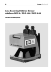
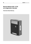
Rotary Encoders
Linear Encoders
Motion
PositioningSystem
BE-90 SSI
• Safety instructions
• Technical data
• Installation
• Commissioning
• Configuration / Parameterization
• Maintenance
TR - E - BA - GB - 0024 - 05
Barcode positioning system BE-90 with SSI interface
03/09/2011
User Manual
TR-Electronic GmbH
D-78647 Trossingen
Eglishalde 6
Tel.: (0049) 07425/228-0
Fax: (0049) 07425/228-33
E-mail: [email protected]
http://www.tr-electronic.de
Copyright protection
This Manual, including the illustrations contained therein, is subject to copyright protection. Use of this Manual by third parties in contravention of copyright regulations is
forbidden. Reproduction, translation as well as electronic and photographic archiving
and modification require the written content of the manufacturer. Offenders will be
liable for damages.
Subject to amendments
Any technical changes that serve the purpose of technical progress, reserved.
Document information
Release date/Rev. date:
Document rev. no.:
File name:
Author:
03/09/2011
TR - E - BA - GB - 0024 - 05
TR-E-BA-GB-0024-05.DOC
MÜJ
Font styles
Italic or bold font styles are used for the title of a document or are used for highlighting.
Courier font displays text, which is visible on the display or screen and software
menu selections.
″<
> ″ indicates keys on your computer keyboard (such as <RETURN>).
Trademarks
PROFIBUS-DP and the PROFIBUS logo are registered trademarks of PROFIBUS
Nutzerorganisation e.V. (PNO) [PROFIBUS User Organization]
SIMATIC is a registered trademark of SIEMENS corporation
© TR-Electronic GmbH 2011, All Rights Reserved
Page 2 of 44
Printed in the Federal Republic of Germany
TR - E - BA - GB - 0024 - 05
03/09/2011
Table of Contents
Table of Contents
Table of Contents .............................................................................................................................3
Revision index ..................................................................................................................................5
1 General Information ......................................................................................................................6
1.1 Explanation of Symbols ...................................................................................................6
2 Safety Notices................................................................................................................................7
2.1 Safety Standards .............................................................................................................7
2.2 Intended Use ...................................................................................................................7
2.3 Working Safely.................................................................................................................8
3 Description .....................................................................................................................................10
3.1 BE-90 device construction...............................................................................................10
3.2 Application .......................................................................................................................10
3.3 Function ...........................................................................................................................11
3.4 Advantages......................................................................................................................11
3.5 Standalone operation ......................................................................................................11
4 Technical Data ...............................................................................................................................13
4.1 General Specifications BE-90..........................................................................................13
4.2 Barcode band ..................................................................................................................14
4.3 LED-indicators .................................................................................................................14
4.4 Dimensioned and Connection Drawings .........................................................................15
5 Barcode tape..................................................................................................................................16
5.1 General information .........................................................................................................16
5.2 Specifications of the barcode tape ..................................................................................17
5.3 Mounting the barcode tape..............................................................................................18
6 Accessories / Order Designation.................................................................................................21
6.1 Read head, RH (stand-alone unit)...................................................................................21
6.2 Connection-Unit, CU........................................................................................................22
6.3 Software, SW...................................................................................................................23
6.4 Cable Set, CA ..................................................................................................................24
6.5 Fastening Accessories, FA..............................................................................................25
6.6 Special Barcode band, BC ..............................................................................................26
6.6.1 Special barcode band (replacement)...............................................................26
7 Installation......................................................................................................................................27
7.1 Storage, Transportation ...................................................................................................27
7.2 Mounting ..........................................................................................................................28
7.2.1 Device Arrangement ........................................................................................29
7.3 Connection.......................................................................................................................32
7.3.1 Connecting BE-90 (SSI) ..................................................................................32
7.3.2 Connection SSI interface .................................................................................33
7.3.3 Connection of switching input and output........................................................35
© TR-Electronic GmbH 2011, All Rights Reserved
Printed in the Federal Republic of Germany
03/09/2011
TR - E - BA - GB - 0024 - 05
Page 3 of 44
Table of Contents
7.3.4 Wire Lengths and Shielding.............................................................................36
7.4 Disassembling, Packing, Disposing.................................................................................36
8 Commissioning..............................................................................................................................37
8.1 Measures to be performed prior to the initial commissioning..........................................37
8.2 Function Test ...................................................................................................................37
8.3 Setting the Parameters ....................................................................................................37
8.3.1 Parameter sets.................................................................................................38
8.3.2 Service Operating Mode ..................................................................................38
9 Operation........................................................................................................................................39
9.1 Display Elements .............................................................................................................39
10 Communicating with the Device ................................................................................................40
10.1 Installing the configuration software ..............................................................................40
10.2 Overview of Commands and Parameters......................................................................42
10.2.1 General ’Online’ Commands..........................................................................42
10.2.2 General parameter structure..........................................................................43
11 Maintenance.................................................................................................................................44
11.1 General Maintenance Information .................................................................................44
11.2 Repairs, Servicing..........................................................................................................44
© TR-Electronic GmbH 2011, All Rights Reserved
Page 4 of 44
Printed in the Federal Republic of Germany
TR - E - BA - GB - 0024 - 05
03/09/2011
Revision index
Revision index
Revision
Date
Index
First release
05/02/2002
00
Correction of the operating range
01/28/2003
01
11/13/2003
02
- Note:
No use into environments with direct sunlight exposure
11/14/2006
03
- New chapter added "5 Barcode tape"
05/06/2009
04
03/09/2011
05
- Additional information about the laser radiation in chap. "Working Safely"
- New SSI format as of V 01.06 in chap. "Technical Data"
- Additional information's about the connection of the protective conductor PE
- Operating range modified
- Mounting drawing for fastener added
© TR-Electronic GmbH 2011, All Rights Reserved
Printed in the Federal Republic of Germany
03/09/2011
TR - E - BA - GB - 0024 - 05
Page 5 of 44
General Information
1 General Information
1.1 Explanation of Symbols
The symbols used in this operating manual are explained below.
Attention
Play attention to passages marked with this symbol. Failure to heed this information can
lead to injuries to personnel or damage to the equipment.
Attention Laser
This symbol warns of possible danger through hazardous laser radiation.
i
Notice
This symbol indicates text passages containing important information.
© TR-Electronic GmbH 2011, All Rights Reserved
Page 6 of 44
Printed in the Federal Republic of Germany
TR - E - BA - GB - 0024 - 05
03/09/2011
Safety Notices
2 Safety Notices
2.1 Safety Standards
The barcode positioning system BE-90 and the optional connection units have been developed, produced and tested subject to the applicable safety standards. They correspond to the state of the art.
2.2 Intended Use
Attention!
The protection of personnel and the device cannot be guaranteed if the device is operated in a manner not corresponding to its intended use.
Barcode positioning systems of the type BE-90 are optical measuring systems which
use visible red laser light to determine the position of the BE-90 relative to a permanently mounted barcode band.
Typically, the BE-90 is mounted on a (rail-)guided vehicle whose position is to be exactly determined.
The position is determined to within a millimeter using the information of the fixed barcode band and made available to the primary system at a suitable interface.
The optional connector and interface units are intended for the easy connection of barcode positioning systems of type BE-90
In particular, unauthorized uses include:
•
•
•
rooms with explosive atmospheres
operation for medical purposes
into environments with direct sunlight exposure or with suitable protection device only
Areas of application
The barcode positioning system BE-90 with optional connection unit has been designed
particularly for the following fields of application:
•
•
•
•
•
High-bay storage devices and lifting gear
Crane systems
Side-tracking skates
Transfer machines
Telpher lines
© TR-Electronic GmbH 2011, All Rights Reserved
Printed in the Federal Republic of Germany
03/09/2011
TR - E - BA - GB - 0024 - 05
Page 7 of 44
Safety Notices
2.3 Working Safely
Attention Laser Radiation!
The barcode positioning system BE-90 operates with a red light laser of class 2
acc. to EN 60825-1 (2001/11). It also complies with the U.S. 21 CFR 1040 regulations for a class II product. If you look into the beam path over a longer time period, the retina of your eye may be damaged!
Never look directly into the beam path!
Do not point the laser beam of the BE-90 at persons!
When mounting and aligning the BE-90, take care to avoid reflections of the laser beam off reflective surfaces!
The use of operating and adjusting devices other than those specified in this
technical description, carrying out of differing procedures, or improper use of
the barcode positioning system may lead to dangerous exposure to radiation!
The use of optical instruments or devices in combination with the device increases the danger of eye damage!
Adhere to the applicable legal and local regulations regarding protection from
laser beams acc. to EN 60825-1 in its latest version.
The BE-90 uses a laser diode with low power in the visible red light range with
an emitted wavelength of about 650nm. The output power of the laser beam at
the reading window is at most 1.8 mW acc. to EN 60825-1 (2001/11).
The reading window is the only opening through which the laser radiation can
escape from the device. The housing of the BE-90 is sealed and has no parts
that need to be adjusted or maintained by the user. The device must not be
tampered with and must not be changed in any way!
i
Notice!
It is important that you attach the sticky labels supplied to the device (notice signs and
laser emission symbol)! If the signs would be covered due to the installation situation
of the BE-90, attach them close to the BE-90 such that reading the notices cannot
lead to looking into the laser beam!
© TR-Electronic GmbH 2011, All Rights Reserved
Page 8 of 44
Printed in the Federal Republic of Germany
TR - E - BA - GB - 0024 - 05
03/09/2011
Safety Notices
LASER LIGHT – DO NOT STARE INTO BEAM
CLASS 2 LASER PRODUCT
Maximum output:
1.8mW
Pulse duration:
120µs
Emitted wavelength: 650...690nm
EN60825-1: 2001-11
CLASS II LASER PRODUCT
Maximum output:
1.8mW
Pulse duration:
60µs
Emitted wavelength: 650...690nm
Complies with 21 CFR 1040.10
Figure 2-1: Example for the attachment of the sticky label with warning notices
Attention!
Access to or changes on the device, except where expressly described in this operating
manual, is not authorized.
Safety regulations
Observe the locally applicable legal regulations and the rules of the employer's liability
insurance association.
Qualified personnel
Mounting, commissioning and maintenance of the device must only be carried out by
qualified personnel.
Electrical work must be carried out by a certified electrician.
© TR-Electronic GmbH 2011, All Rights Reserved
Printed in the Federal Republic of Germany
03/09/2011
TR - E - BA - GB - 0024 - 05
Page 9 of 44
Description
3 Description
Information on technical data and characteristics can be found in chapter 4.
3.1 BE-90 device construction
Figure 3-1: BE-90 device construction
3.2 Application
Anywhere systems are moved automatically, it is necessary to correctly determine their
positions. This is achieved using various measurement techniques. In addition to mechanical measurement sensors, optical methods are particularly well suited for determining positions as they operate without mechanical wear and slippage.
Unlike other optical measurement methods, the barcode positioning system is not restricted to linear movements. It can also be used flexibly in curved systems. Anywhere
the longwearing barcode band can be attached, it is possible to use the BE-90 to determine the position to within a millimeter.
Guide tolerances of the system play no roll as the permitted separation between band
and BE-90 allows for large deviations in distance.
© TR-Electronic GmbH 2011, All Rights Reserved
Page 10 of 44
Printed in the Federal Republic of Germany
TR - E - BA - GB - 0024 - 05
03/09/2011
Description
3.3 Function
The BE-90 uses visible red laser light to determine its position relative to the barcode
band. This essentially takes place in three steps:
1.
Reading a code on the barcode band
2.
Determining the position of the read code in the scanning area of the laser beam
3.
Calculating of the position to within a millimeter using the code information and
the code position
The position value is then passed on via the standardized SSI interface (synchronous
serial interface) to the drive system of the vehicle for which the position is to be determined.
3.4 Advantages
•
Easy installation and commissioning
•
Teach-function for the “zero point”, i.e. it is not necessary to exactly affix the barcode band.
•
Data output via SSI interface; BE-90 can be connected instead of a conventional
rotation encoder.
•
The function of the BE-90 makes it possible to attach the barcode band only at
those locations where it is necessary that the positions be known exactly.
•
Positioning of non-linear movements as well
•
No referencing necessary following voltage drop
•
Thanks to the large scanning depth, it is possible to compensate for mechanical
tolerances.
•
It is possible to exactly determine positions from distances of 10000 metres.
3.5 Standalone operation
The barcode positioning system BE-90 is operated as a single “stand alone” device.
The BE-90 features a 15-pin SUB-D connector for the electrical connection of the supply voltage, the interface and the switching inputs.
With connection units
The connection units simplify the electrical installation of the barcode positioning system
in stand-alone operation.
Moreover, they store the operating parameters so that the configuration data are retained even if the BE-90 is replaced and can show parameters and operating data on a
display.
A listing of the available connection units and associated short descriptions can be
found in chapter 6.
© TR-Electronic GmbH 2011, All Rights Reserved
Printed in the Federal Republic of Germany
03/09/2011
TR - E - BA - GB - 0024 - 05
Page 11 of 44
Description
Without connection unit
Figure 3-2: Connection BE-90 "Stand alone"
With connection unit
Figure 3-3: BE-90 connection with connection unit
© TR-Electronic GmbH 2011, All Rights Reserved
Page 12 of 44
Printed in the Federal Republic of Germany
TR - E - BA - GB - 0024 - 05
03/09/2011
Technical Data
4 Technical Data
4.1 General Specifications BE-90
Optical Data
Light source
Scanning rate
Laser diode 650 nm
1000 scans/sec.
Measurement data
Reproducible accuracy
Integration time
Measurement value output
Scanning depth
±1 (2) mm
16 (8) ms
500 values/sec.
90 … 170 mm
Electrical Data
Interface type
(standard setting)
Ports
LED green
Operating voltage
Power consumption
SSI (RS422)
electrically isolated
bits 0 … 24: data bits with position value
bit 25: error bit
resolution: 1mm
800 kHz max. clock frequency
output of positive and negative position values
Gray coded
RS232 with fixed data format,
9600 baud, 8 data bits, no parity, 1 stop bit
1 switching output, 1 switching input
device ready (Power On)
10 ... 30 V
3.2 W
Mechanical Data
Protection class
Weight
Dimensions (W x H x D)
Housing
IP 65
400 g
120 x 90 x 43 mm
diecast aluminum
Service Interface
Environmental data
Operation without optics heating
Operation with optics heating
Storage
Air humidity
Vibration
Electromagnetic compatibility
0°C ... +40°C
-30°C ... +40°C
-20°C ... +60°C
max. 90% rel. humidity, non-condensing
IEC 68.2.6
IEC 68.2.27 (shock)
IEC 801
acc. to IEC 60947-5-2
Table 4-1: General Specifications BE-90
© TR-Electronic GmbH 2011, All Rights Reserved
Printed in the Federal Republic of Germany
03/09/2011
TR - E - BA - GB - 0024 - 05
Page 13 of 44
Technical Data
4.2 Barcode band
Max. length (measurement length) 10 000 m
Ambient temperature
-40°C ... +120°C
Mechanically characteristics
Resistantly against scratch and wipe, UV-light,
humidity, chemicals and solvents (restricted).
Further details see page 16, and the following pages.
4.3 LED-indicators
An internal LED indicates in the reading window whether or not the supply voltage is
present.
© TR-Electronic GmbH 2011, All Rights Reserved
Page 14 of 44
Printed in the Federal Republic of Germany
TR - E - BA - GB - 0024 - 05
03/09/2011
Technical Data
4.4 Dimensioned and Connection Drawings
BE-90
Figure 4-1: Dimensioned drawing BE-90
Scanning curve BE-90
Figure 4-2: Scanning curve BE-90
© TR-Electronic GmbH 2011, All Rights Reserved
Printed in the Federal Republic of Germany
03/09/2011
TR - E - BA - GB - 0024 - 05
Page 15 of 44
Barcode tape
5 Barcode tape
5.1 General information
The barcode tape is delivered on a roll. A roll contains up to 200m of barcode tape,
with the wrapping direction from the outside to the inside (smallest number on the outside). If a barcode tape is ordered which is considerably longer than 200m, the total
length is divided into rolls of 200m each.
Figure 5-1: Roll with barcode tape
Features:
• Robust and durable polyester adhesive tape
• High dimensional stability
• Max. length 10.000 m
• Self-adhesive, high adhesive strength
© TR-Electronic GmbH 2011, All Rights Reserved
Page 16 of 44
Printed in the Federal Republic of Germany
TR - E - BA - GB - 0024 - 05
03/09/2011
Barcode tape
5.2 Specifications of the barcode tape
Dimensions
Standard height
47 mm (other heights on request)
Length
0 … 5 m, 0 … 10 m, 0 … 20 m, …, 0 … 150 m,
0 … 200 m, special lengths and special codings
for lengths from150 m
Construction
Manufacturing process
Filmsetting
Surface protection
Polyester, matt
Base material
Polyester film, affixed without silicone (0.08mm)
Adhesive
Acrylate adhesive
Adhesive thickness
0.1 mm
Adhesive strength
(average values)
on aluminium:
25 N/25 mm
on steel:
25 N/25 mm
on polycarbonate:
22 N/25 mm
on polypropylene:
20 N/25 mm
Environmental data
Recom. processing temperature
0 °C … +45 °C
Temperature resistance
-40 °C … +120 °C
Dimensional stability
no shrinkage, tested according to DIN 30646
Curing
final curing after 72 h, the position can be detected immediately by the BE-90 after the barcode tape is affixed
Thermal expansion
due to the high elasticity of the barcode tape,
thermal expansion of the base material on which
the barcode tape is affixed is not known to have
an effect
Tearing resistance
150N
Elongation at tear
min. 80 %, tested in accordance with
DIN 50014, DIN 51220
Weathering resistance
UV-light, humidity, salt spray (150h/5%)
Chemical resistance
(tested at 23 °C for 24 h)
transformer oil, diesel oil, white spirit, heptane,
ethylene glycol (1:1)
Behaviour in fire
self-extinguishing after 15 s, does not drip
Mounting surface
grease-free, dry, clean, smooth
Table 5-1: Specifications of the barcode tape
© TR-Electronic GmbH 2011, All Rights Reserved
Printed in the Federal Republic of Germany
03/09/2011
TR - E - BA - GB - 0024 - 05
Page 17 of 44
Barcode tape
5.3 Mounting the barcode tape
To prevent deposits of dirt from forming, it is recommended that the barcode tape be
affixed vertically, possibly with a roof-like cover. If the application does not permit this,
permanent cleaning of the barcode tape by on-board cleaning devices such as
brushes or sponges is not permitted in any case. Permanent on-board cleaning devices polish the barcode tape and give it a glossy finish. The read quality deteriorates
as a result.
i
Notice!
When mounting the barcode tape, it must be ensured that neither strong sources of
extraneous light nor reflections of the base on which the barcode tape is affixed occur
in the area of the scanning beam.
The recommended interruption points on the barcode tape are at the provided cut
marks.
Figure 5-2: Cut mark on the barcode tape
i
Notice!
Cutting the barcode tape and affixing the tape so that a gap forms which is so large
that a label can no longer be reliably detected in the scanning beam results in double
positions during the position calculation of the BE-90. The gap must not be greater
than the distance from one cut mark to the next (max. one label).
Figure 5-3: Gap in the cut barcode tape
© TR-Electronic GmbH 2011, All Rights Reserved
Page 18 of 44
Printed in the Federal Republic of Germany
TR - E - BA - GB - 0024 - 05
03/09/2011
Barcode tape
Procedure:
• Examine the mounting surface. It must be flat, without warping, free of grease and
dust, and dry.
• Define a reference edge (e.g. metal edge of the busbar)
• Remove the backing and affix the barcode tape along the reference edge tension
free. Secure the barcode tape to the mounting surface by pressing down with the
palm of your hand. When affixing, make certain that the barcode tape is free of folds
and creases and that no air pockets form.
• Never pull the barcode tape. Because this is a plastic tape, forceful pulling may
stretch it. This results in a distortion of the measurement units on the tape. While the
BE-90 can still perform the position calculation, the accuracy in this case is no longer
ensured. If the values are taught using a teach-in process, distortions are irrelevant.
• Expansion joints with widths up to several millimetres can simply be covered with the
barcode tape. The tape must not be interrupted at this location.
• Protruding screw heads can simply be taped over. Cut out the bar code which covers
the screw head at the cut marks.
• If the application dictates the necessity of a gap, the tape is to be affixed over this
gap and the affected cut marks cut out. If the gap is small enough that the scanning
beam can detect the label to the left or to the right of the gap, measurement values
are delivered without interruption. If the scanning beam cannot completely scan any
label, the BE-90 returns the value 0. As soon as the BE-90 can again scan a complete label, it calculates the next position value.
• The maximum gap between two barcode positions without affecting the measurement value is 40 mm.
Attention!
Barcode tapes with different value ranges may not directly follow one another. If the value
ranges are different, the gap between the two barcode tapes must be greater than the detection range of the scanning beam or control barcodes must be used.
© TR-Electronic GmbH 2011, All Rights Reserved
Printed in the Federal Republic of Germany
03/09/2011
TR - E - BA - GB - 0024 - 05
Page 19 of 44
Barcode tape
i
Notice!
When working with the barcode tap in cold warehouses, it should be ensured that the barcode tap be affixed before the warehouse is cooled. However, if it should be necessary to
work with the barcode tap at temperatures outside of the specified processing temperature,
please make certain that the bonding surface as well as the barcode tap are at the processing temperature.
i
Notice!
When working with barcode tape in curves, the barcode tape should only be partially cut at
the cut mark and affixed along the curve like a fan; it must also be ensured that the barcode
tape is affixed without tension (see Figure 5-4).
Figure 5-4: Partial cutting of the barcode tape in curves
© TR-Electronic GmbH 2011, All Rights Reserved
Page 20 of 44
Printed in the Federal Republic of Germany
TR - E - BA - GB - 0024 - 05
03/09/2011
Accessories / Order Designation
6 Accessories / Order Designation
i
Notice!
Products manufactured by TR-Electronic GmbH can be ordered from any of the
distributor and service addresses listed on the last page.
6.1 Read head, RH (stand-alone unit)
Explanation of the
order designation
The order designation is structured according to the following scheme:
40803-1ABCD
The letters A - D represent the following device variants:
•
A interface
1 = SSI (synchronous-serial)
2 = PROFIBUS, RS485
•
B extension
always 0
•
C extension
always 0
•
D option (H)
0 = without option
1 = -30 - +40°C
Available device variants:
BE-90 RH SSI 40803-11000
Read Head SSI without option
BE-90 RH SSI + H 40803-11001
Read Head SSI with option -30 - +40°C
BE-90 RH PB 40803-12000
Read Head Profibus without option
BE-90 RH PB + H 40803-12001
Read Head Profibus with option -30 - +40°C
RH
SSI
PB
H
= Read Head
= Synchronous-Serial-Interface
= Profibus
= Heating
Please indicate these designations at the order.
© TR-Electronic GmbH 2011, All Rights Reserved
Printed in the Federal Republic of Germany
03/09/2011
TR - E - BA - GB - 0024 - 05
Page 21 of 44
Accessories / Order Designation
6.2 Connection-Unit, CU
Explanation of the
order designation
The order designation is structured according to the following scheme:
40803-2ABCD
The letters A - D represent the following device variants:
•
A interface
1 = SSI interface box, programmable with
parameter memory
•
B extension
always 0
•
C extension
always 0
•
D option
0 = without display
1 = extension
Available device variants:
BE-90 CU SSI 40803-21000
CU
SSI
Connection-Unit SSI without display
= Connecting Unit
= Synchronous-Serial-Interface
Please indicate these designations at the order.
i
Notice!
The connection unit is described here in brief only. For further information regarding the
connection unit please refer to the relevant data sheets
The connection unit is used to simplify the electrical installation of the BE-90. It has
the following advantages compared to the installation of the BE-90 as a standalone
device:
•
Terminals for switching inputs and outputs, including supply voltage
•
9-pin sub-D plug for service interface
•
Operating mode switch: service operation/standard operation
•
Code types – changeover switches binary/Gray
•
Rotary switch for setting the resolution
•
Parameter memory for the BE-90 – the positioning system can be exchanged
without the need for reconfiguration.
•
Display (SSI variant only)
© TR-Electronic GmbH 2011, All Rights Reserved
Page 22 of 44
Printed in the Federal Republic of Germany
TR - E - BA - GB - 0024 - 05
03/09/2011
Accessories / Order Designation
Figure 6-1: Connection unit BE-90 / dimensioned drawing
6.3 Software, SW
Explanation of the
order designation
The order designation is structured according to the following scheme:
40803-3ABCD
The letters A - D represent the following software variants:
•
A
interface
1 = SSI (Synchronous-Serial)
2 = PROFIBUS, RS485
•
BCD
software-no.
until now "000" for both variants
Available software variants:
BE-90 SW SSI 40803-31000
SSI software variant
BE-90 SW PB 40803-32000
Profibus software variant, device master files (GSD)
SW
SSI
PB
= Software
= Synchronous-Serial-Interface
= Profibus
Please indicate these designations at the order.
© TR-Electronic GmbH 2011, All Rights Reserved
Printed in the Federal Republic of Germany
03/09/2011
TR - E - BA - GB - 0024 - 05
Page 23 of 44
Accessories / Order Designation
6.4 Cable Set, CA
For the connection between BE-90 and SSI-Connection-Unit a special connection-cable
is available.
Explanation of the
order designation
The order designation is structured according to the following scheme:
40803-4ABCD
The letters A - D represent the following cable variants:
•
A extension
always 0
•
B extension
always 0
•
C extension
always 0
•
D cable set variant 1 = cable set, 15 pin Sub-D, without connector
2 = cable set, 15 pin Sub-D, with 12 pin Contact-Connector
Available cable variants:
BE-90 CA-3M 40803-40001
Cable set for Read-Head and SSI-Connection-Unit with 3 m length
BE-90 CA-3M 12P 40803-40002 Cable set for Read-Head and SSI-Connection-Unit with 3 m length, 12 pin Contact
Pin assignment, cable set BE-90 CA-3M 12P 40803-40002
Function
15 pin SUB-D (female)
Color
GND
1
red/blue
7
SWIN 1
2
white
9
SSI-Data +
3
pink
3
SSI-Data -
4
gray
4
NC
5
black
NC
SSI-clock +
6
white/green
2
/Serv
7
gray/pink
8
US = 10 - 30 V
8
red
11
SSI-clock -
9
brown
1
SWOUT 1
10
white/yellow
10
RXD
11
yellow
5
TXD
12
green
6
NC
13
violet
NC
NC
14
brown/green
NC
GND 0V
15
blue
12
© TR-Electronic GmbH 2011, All Rights Reserved
Page 24 of 44
12 pin Contact Connector
Printed in the Federal Republic of Germany
TR - E - BA - GB - 0024 - 05
03/09/2011
Accessories / Order Designation
6.5 Fastening Accessories, FA
The mounting unit is available for mounting the BE-90. It is designed for rod installation.
Explanation of the
order designation
The order designation is structured according to the following scheme:
40803-5ABCD
The letters A - D represent the following mounting variants:
•
A extension
always 0
•
B extension
always 0
•
C extension
always 0
•
D mounting element
1 = Mounting element BE-90 / Connection-Unit
Available mounting variants:
BE-90 FA-001 40803-50001
FA
Mounting element (dove tail for round pipes) between
BE-90 and connection-unit
= Fastener
Please indicate these designations at the order.
Figure 6-2: Mounting element BE-90
© TR-Electronic GmbH 2011, All Rights Reserved
Printed in the Federal Republic of Germany
03/09/2011
TR - E - BA - GB - 0024 - 05
Page 25 of 44
Accessories / Order Designation
6.6 Special Barcode band, BC
Explanation of the
order designation
The order designation is structured according to the following scheme:
40803-6ABCD
The letters A - D represent the following barcode band length
•
ABCD
barcode band
length
Total length in 10 m steps
The length begins with the first meter
Example: 40803-60002 = 20 m (0 - 20 m)
Available barcode band lengths:
BE-90 BC 020 40803-60000
Barcode band, 0 - 5 m length
BE-90 BC 010 40803-60001
Barcode band, 0 - 10 m length
BE-90 BC 020 40803-60002
Barcode band, 0 - 20 m length
BE-90 BC 030 40803-60003
Barcode band, 0 - 30 m length
BE-90 BC 040 40803-60004
Barcode band, 0 - 40 m length
BE-90 BC 050 40803-60005
Barcode band, 0 - 50 m length
BE-90 BC 060 40803-60006
Barcode band, 0 - 60 m length
BE-90 BC 070 40803-60007
Barcode band, 0 - 70 m length
BE-90 BC 080 40803-60008
Barcode band, 0 - 80 m length
BE-90 BC 090 40803-60009
Barcode band, 0 - 90 m length
BE-90 BC 100 40803-60010
Barcode band, 0 - 100 m length
BE-90 BC 200 40803-60020
Barcode band, 0 - 200 m length
BC
= Barcode band
Please indicate these designations at the order.
6.6.1 Special barcode band (replacement)
Must, by a damage caused, only a certain part of a barcode band to be replaced, the
damaged bar code piece can be reordered. The article number BE-90 BC SA 4080370001 must be indicated with specification of the start- and end-value of the damaged
barcode band.
© TR-Electronic GmbH 2011, All Rights Reserved
Page 26 of 44
Printed in the Federal Republic of Germany
TR - E - BA - GB - 0024 - 05
03/09/2011
Installation
7 Installation
7.1 Storage, Transportation
Attention
When transporting, package the device so that it is protected against collision and humidity. Optimal protection is achieved when using the original packaging. Heed the required environmental conditions specified in the technical data.
Unpacking
•
Check the packaging for any damage. If damage is found, notify the post office or
shipping agent as the supplier.
•
Check the delivery contents using your order and the delivery papers:
- delivered quantity
- device type and model as indicated on the nameplate
- accessories
- operating manual
•
Save the original packaging for later storage or shipping.
If you have any questions concerning your shipment, please contact your supplier or
your local TR-Electronic sales office.
•
Observe the local regulations regarding disposal and packaging.
Cleaning
•
Clean the glass window of the BE-90 with a soft cloth before mounting. Remove
all packaging remains, e.g. carton fibers or Styrofoam balls.
Attention!
Do not use aggressive cleaning agents such as thinner or acetone for cleaning the device and the barcode band.
© TR-Electronic GmbH 2011, All Rights Reserved
Printed in the Federal Republic of Germany
03/09/2011
TR - E - BA - GB - 0024 - 05
Page 27 of 44
Installation
7.2 Mounting
Accessories
For mounting a mounting system is available. It may be ordered separately from TRElectronic. For order numbers, see page 25.
Mounting the BE-90
There are two basic types of mounting arrangements for the BE-90:
•
using the dovetail groove and the corresponding mounting accessories
(see Figure 6-2, page 25)
•
using the fastening threads on the back- and underside of the devices
(see Figure 4-1: Dimensioned drawing BE-90)
Mounting example BE-90
Figure 7-1: Mounting example BE-90
Mounting
You can mount all connection units individually through the holes located on the mounting plate (see Figure 6-1, page 23).
Subsequently, connect the BE-90 with the connection unit via the respective cable (see
chapter 6.4, page 24).
© TR-Electronic GmbH 2011, All Rights Reserved
Page 28 of 44
Printed in the Federal Republic of Germany
TR - E - BA - GB - 0024 - 05
03/09/2011
Installation
7.2.1 Device Arrangement
Selecting a mounting location
In order to select the right mounting location, several factors must be considered:
•
The scanning range determined from the scanning curve must be adhered to at all
locations at which a position determination is to be made.
•
The BE-90 should be mounted inclined 10° from vertical towards the barcode
band to ensure that the read results are reliably obtained even if the barcode band
is soiled.
Figure 7-2: Device arrangement to the code band
i
i
Notice
The best functionality is obtained when:
• the BE-90 is guided parallel to the band
• the permitted working range is not exited
Notice
On the BE-90, the beam is not emitted perpendicular to the cover of the housing, but
with an angle of 10° towards the top. This angle is intended to prevent total reflection on
the barcode band.
© TR-Electronic GmbH 2011, All Rights Reserved
Printed in the Federal Republic of Germany
03/09/2011
TR - E - BA - GB - 0024 - 05
Page 29 of 44
Installation
Figure 7-3: Beam outlet on the BE-90
Mounting location
•
When selecting a mounting location, pay attention to
-
maintaining the required environmental conditions (humidity, temperature).
-
possible soiling of the reading window due to liquids, abrasion by boxes, or
packaging material residues.
-
lowest possible change of damage to the scanner by mechanical collision or
jammed parts.
© TR-Electronic GmbH 2011, All Rights Reserved
Page 30 of 44
Printed in the Federal Republic of Germany
TR - E - BA - GB - 0024 - 05
03/09/2011
Installation
Application example
Figure 7-4: Application example
© TR-Electronic GmbH 2011, All Rights Reserved
Printed in the Federal Republic of Germany
03/09/2011
TR - E - BA - GB - 0024 - 05
Page 31 of 44
Installation
7.3 Connection
Attention!
Never open the device yourself, as this may compromise protection class IP 65.
Before connecting the device, be sure that the supply voltage agrees with the value
printed on the nameplate.
Connecting the device and maintenance work while under voltage must only be carried
out by a qualified electrician.
The power supply unit for the generation of the supply voltage for the BE-90 and the respective connection units must have a secure electrical insulation via double insulation
and safety transformers according to DIN VDE 0551 (IEC 742).
BE sure that the earthing conductor is connected correctly. Error-free operation is only
guaranteed when the device is properly earthed.
If faults cannot be corrected, the device should be removed from operation and protected against possible use.
7.3.1 Connecting BE-90 (SSI)
BE-90 sub-D pin assignments
Figure 7-5: BE-90 sub-D pin assignments
© TR-Electronic GmbH 2011, All Rights Reserved
Page 32 of 44
Printed in the Federal Republic of Germany
TR - E - BA - GB - 0024 - 05
03/09/2011
Installation
Wiring description
Pin 1
Pin 2
Pin 3
Pin 4
Pin 5
Pin 6
Pin 7
Pin 8
Pin 9
Pin 10
Pin 11
Pin 12
Pin 13
Pin 14
Pin 15
GND
SWIN1
SSI-data+
SSI-dataReserved
SSI-clock+
/Serv
VIN
SSI-clockSWOUT1
RXD/Serv
TXD/Serv
Reserved
Reserved
GND
Ground reference RS 422 / SSI
Switching input 1 (+12 ... 30 VDC)
SSI data line
SSI data line
SSI clock line
Bridge to pin 15: service operation via RS232 interface
Supply voltage +10 ... 30VDC
SSI clock line
Switching output 1 (max. 100 mA)
RXD signal, service interface RS 232
TXD Signal, service interface RS 232
Supply voltage 0VDC
Table 7-1: Connection description BE-90
7.3.2 Connection SSI interface
Connection unit
Terminals
Control/Drive
SSI interface
Figure 7-6: Connection unit
© TR-Electronic GmbH 2011, All Rights Reserved
Printed in the Federal Republic of Germany
03/09/2011
TR - E - BA - GB - 0024 - 05
Page 33 of 44
Installation
Connection BE-90 direct
Pin
Control/Drive
SSI interface
Figure 7-7: Connection BE-90 direct
i
Notice!
Ensure adequate shielding. Connections 1 and 2 must be twisted pairs and the total
connection line must be shielded and grounded at one end.
Attention!
It is absolutely necessary to connect the protective conductor, since all electrical interference (EM pick-up) is discharged via the protective conductor connection.
Connection of the protective conductor PE
BE-90 without cable:
Connect PE to the housing of the BE-90 or to the housing of the 15-pin SUB-D connector!
BE-90 with cable:
Connect PE to the wire with bl/wh color coding or connect it to the shield!
BE-90 with cable and connection-unit:
Connect PE to PIN 21 or PIN 22!
© TR-Electronic GmbH 2011, All Rights Reserved
Page 34 of 44
Printed in the Federal Republic of Germany
TR - E - BA - GB - 0024 - 05
03/09/2011
Installation
7.3.3 Connection of switching input and output
The BE-90 is provided with a switching input and a switching output. The connection of
the switching input and output is made according to Figure 7-8:
Figure 7-8: Connection diagram switching inputs and outputs BE-90
Switching input
In the standard setting you can use the switching input connection SWIN1 to reset output of the position measurement data to zero by applying a voltage of 12...30VDC between SWIN1 (pin 2) and GND (pin 15)
Switching output
The switching output connection between SWOUT1 (pin 10) and GND (pin 15) is normally open. In the standard setting, SWOUT1 is closed in the event of a positioning error.
You can configure the switching inputs and outputs according to your needs, using the
supplied BE-90 configuration program.
© TR-Electronic GmbH 2011, All Rights Reserved
Printed in the Federal Republic of Germany
03/09/2011
TR - E - BA - GB - 0024 - 05
Page 35 of 44
Installation
7.3.4 Wire Lengths and Shielding
The following maximum lengths for wires and the type of shielding to be used must be
observed:
Connecting
BE-90 - Service
BE-90/connection
unit
Interface
Max. wire length
RS 232
10 m
SSI
1200 m
Shielding
absolutely required,
shield meshing
absolutely required,
flexible leads as twisted
pairs and shielded
Switching input
10 m
not necessary
Switching output
10 m
not necessary
Table 7-2: Wire Lengths and Shielding
7.4 Disassembling, Packing, Disposing
Repacking
For later re-use, the device is to be packed so that it is protected against shocks and
dampness. Optimal protection is achieved when using the original packaging.
i
Notice!
Electrical scrap is a special waste product! Observe the locally applicable regulations
regarding disposal of the product..
© TR-Electronic GmbH 2011, All Rights Reserved
Page 36 of 44
Printed in the Federal Republic of Germany
TR - E - BA - GB - 0024 - 05
03/09/2011
Commissioning
8 Commissioning
8.1 Measures to be performed prior to the initial commissioning
•
Before commissioning, familiarize yourself with the operation and configuration of
the device(s)!
•
Before switching on, recheck all connections and ensure that they have been
properly made.
8.2 Function Test
"Power-On"-test
After connecting the operating voltage, the BE-90 performs an automatic “Power On”
function test. Subsequently, the green LED lights up in the optics window of the BE-90.
Interface
Proper function of the interface can be tested easiest in service operation using the service interface with the parameter-software and a notebook computer. For order numbers, see table 6.3, on page 23.
Online commands
Using the ‘Online’ commands, important device functions can be checked, e.g. proper
functioning of the laser.
Problems
Should a problem persist after checking all electrical connections and setting on the devices and host, please contact a TR-Electronic service-office near you (see the last
page of this operating manual).
8.3 Setting the Parameters
You have now commissioned the BE-90. Usually, you will have to configure it before
you can use it. Using the parameter options made available by the BE-90, you can configure the positioning system to suit your individual area of application. For instructions
regarding the various setting options refer to chapter 10 or to the online help of the configuration program.
The setting is usually accomplished by using the configuration-program, see “Installing
the configuration software” 10.1, page 40.
To understand what is happening during the parameter setting, the following chapter
8.3.1 briefly explains the various parameter sets.
The setting of the parameter sets then takes place in the operating mode “service”,
which is described in chapter 8.3.2 .
© TR-Electronic GmbH 2011, All Rights Reserved
Printed in the Federal Republic of Germany
03/09/2011
TR - E - BA - GB - 0024 - 05
Page 37 of 44
Commissioning
8.3.1 Parameter sets
In the BE-90 three different parameter sets are administered:
•
•
•
parameter set with the default settings in the ROM
current parameter set in the EEPROM
working copy of the current parameter set in the RAM
Before a parameter set is loaded into the memory of the BE-90 processor, the validity of
the parameter set is verified using checksums.
Factory default parameter set
This parameter set contains the default settings made ex works for all BE-90 parameters. It is permanently stored in the ROM of the BE-90. The parameter set with the default settings is loaded into the memory of the BE-90,
•
•
•
the first time the device is commissioned after delivery
following the command “Factory Default” in the parameterization program
if the checksums of the current parameter set are invalid.
Current parameter set
In this parameter set, the current settings for all device parameters are stored. When
the BE-90 is in operation, the parameter set is stored in the EEPROM of the BE-90. The
current set can be stored:
• by copying a valid parameter set from the host computer
• by means of an off-line set-up with the PC set-up program
The current parameter set is loaded into the memory of the BE-90:
•
•
each time the supply voltage is connected
following a software reset
The current parameter set is overwritten by the parameter set with the default settings:
•
by a parameter reset, see Table 10-1, page 42.
8.3.2 Service Operating Mode
Setting the required parameters is carried out easiest in the ’Service’ operating mode.
The Service operating mode makes the following defined operating parameters available on a separately wired RS232 interface, independent from the positioning system
configuration for standard operation:
• transfer rate 9600 baud
• no parity
• 8 data bits
• 1 stop bit
• prefix: STX
• postfix: CR, LF
© TR-Electronic GmbH 2011, All Rights Reserved
Page 38 of 44
Printed in the Federal Republic of Germany
TR - E - BA - GB - 0024 - 05
03/09/2011
Operation
Service interface active
The service interface is activated via a bridge between the pins 7 and 15 on the 15-pin
sub-D connector. If the BE-90 is operated with a connection unit, the service interface is
activated trough a switch in the connection unit.
Connection
You can connect a PC or terminal to the BE-90 via the serial interface and configure the
BE-90 via this connection. For this, you need a crossed RS232 connection cable (null
modem cable) that provides the connections RxD, TxD and GND. A hardware handshake via RTC, CTS is not supported at the service interface.
If the positioning system is connected to a connection unit, you can use the 9-pin
sub-D service connector in the connection unit. For the respective connection specifications please refer to the data sheet of the connection unit.
Service Operating Mode
Figure 8-1: Connecting the service interface to a PC or terminal
9 Operation
9.1 Display Elements
On the BE-90 there is an LED. It signals that the positioning system is ready for operation.
© TR-Electronic GmbH 2011, All Rights Reserved
Printed in the Federal Republic of Germany
03/09/2011
TR - E - BA - GB - 0024 - 05
Page 39 of 44
Communicating with the Device
10 Communicating with the Device
Device parameters can be set via commands or using the easy-to-use configuration
software.
10.1 Installing the configuration software
•
Place the installation CD in your CD drive
•
Call up the installation file (e.g. Set-up.exe)
The following window appears:
Installation window
Figure 10-1: Installation window
•
Confirm the following license agreement and select the installation path in the following window:
© TR-Electronic GmbH 2011, All Rights Reserved
Page 40 of 44
Printed in the Federal Republic of Germany
TR - E - BA - GB - 0024 - 05
03/09/2011
Communicating with the Device
Installation directory
Figure 10-2: Installation directory
•
Confirm your entry with Continue, then follow the installation routine.
For further information, please see the online help for the configuration software.
© TR-Electronic GmbH 2011, All Rights Reserved
Printed in the Federal Republic of Germany
03/09/2011
TR - E - BA - GB - 0024 - 05
Page 41 of 44
Communicating with the Device
10.2 Overview of Commands and Parameters
Online commands can be used to send commands directly to the device for control and
configuration.
For this, the BE-90 has to be connected to a host or service computer via the serial interface. The commands can be sent either via the host or the service interface.
10.2.1 General ’Online’ Commands
Command
Description
M+
Activating the measurement
M-
Deactivating the measurement
MI
Reversing the count direction
With the standard setting, the calculation is performed back
from the max. measurement length (10000 m)
MNxyyyyyyy
Set pre-set value
x = T = value is stored temporarily
(the value is erased after switching on and off)
x = D = value is stored permanently in the EPROM
y = specification of the pre-set value in mm
Example: MND0001000
Current position is set permanently to 1000 mm.
MNR
Deactivates the pre-set value. The unformatted measurement
value is output.
MMxyyyy
Controls the data output via the service interface
x = S = a measurement value is output (Single Shot Mode);
subsequent specification of the time not necessary
x = T =measurement values are output cyclically; time must
be subsequently specified
y = time specification in ms
Example: MMT0500
Measurement values are output via the service interface in a
time interval of 500ms
MM-
Deactivating the function MMTyyyy
If the cyclical output via the service interface is no longer
required, the function must be deactivated using the command MM.
PC20
Resetting all parameters in the BE-90 to TR-Electronic
default values.
Version query
Table 10-1: General ’Online’ Commands
© TR-Electronic GmbH 2011, All Rights Reserved
Page 42 of 44
Printed in the Federal Republic of Germany
TR - E - BA - GB - 0024 - 05
03/09/2011
Communicating with the Device
10.2.2 General parameter structure
Using the configuration program, parameters can be changed via the service interface.
These parameters are divided into individual folders.
The following folders are available:
© TR-Electronic GmbH 2011, All Rights Reserved
Printed in the Federal Republic of Germany
03/09/2011
TR - E - BA - GB - 0024 - 05
Page 43 of 44
Maintenance
11 Maintenance
11.1 General Maintenance Information
Usually, the barcode positioning system BE-90 does not require any maintenance by
the operator.
Cleaning
Should it become soiled, clean the glass window of the BE-90 with a soft cloth.
i
Notice!
Do not the aggressive cleaning agents such as thinner or acetone for cleaning the device.
11.2 Repairs, Servicing
Repairs to the device must only be carried out by the manufacturer.
•
Contact your TR-Electronic distributor or service organization should repairs be
required. For addresses, please refer to the last page of this operating manual.
© TR-Electronic GmbH 2011, All Rights Reserved
Page 44 of 44
Printed in the Federal Republic of Germany
TR - E - BA - GB - 0024 - 05
03/09/2011