1
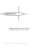
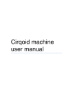
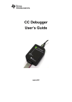
Grids user manual
Overview
Download the quick start guide.
Mutable Instruments’ Grids is a 3-channel trigger generator specialized in the creation
and sculpting of rhythmic patterns.
At the core of Grids is a map, which has been obtained through machine learning
techniques, of the drum patterns used in a large collection of electronic music tracks and
drum loops. The skeleton and structure of the rhythm is programmed by selecting its X
and Y coordinates on the map – with smooth interpolation/morphing between points.
Once this skeleton is in place, variations can be generated by controlling the “event
density” of each of the three channels – gradually morphing from a sparse backbone to a
frantic pattern. X / Y map position, and the density of the 3 channels are all CVcontrollable, allowing rhythmic variations to be created by any modulation source. In
contrast to Euclidean sequencers which are purely algorithmic, Grids’ has “learned”
patterns from actual data and with the right settings might generate a breakbeat or an
influential Kraftwerkian beat.
Most patterns are best played with channel 1 = BD ; channel 2 = SD ; channel 3 = HH,
but experimentation with other sound sources is of course encouraged.
Grids has a built-in clock, or it can accept external clock signals of variable resolution.
Installation
Mutable Instruments’ Grids is designed for Eurorack synthesizer systems and occupies
16 HP of space. It requires a -12V / +12V / +5V supply (2×8 connector), consuming 1mA
from the -12V rail and 25mA from the +5V rail (the +12V rail is actually not used). The
red stripe of the ribbon cable must be oriented on the same side as the “Red stripe”
marking on the printed circuit board.
Grids’ pattern generation algorithm
Grids is a 3-channel, algorithmic, rhythmic pattern generator based on data and models
extracted from actual BD drum loops. Two steps are involved in the generation of the
drum patterns:
Step 1: Synthesizing a pattern from the drum map…
A collection of drum loops has been spatially organized and compressed into a 2dimensional map. Using interpolation techniques, any pair of X/Y coordinates can be
translated into a rhythm, with smooth morphing from one rhythm into the other.
Step 2: … and sculpting it!
Once a rhythmic skeleton is read from the map, variations can be generated by
controlling the note density of each of the three channels – gradually morphing the
pattern from a sparse backbone to a frantic pattern.
Controls
A: Internal clock rate. Ranges from 40 BPM to 240 BPM. When turned fully counterclockwise, the internal clock is disabled and the unit expects a clock signal on its CLOCK
input.
B: Tap (reset). This button acts as a tap tempo, and flashes on each beat. Tap it twice
or more to set the tempo. The duration between the two most recent taps defines the
duration of a beat. Once the tempo has been programmed with the tap tempo button,
the CLOCK knob is locked and has no effect on the rhythm. Tap just once on the Tap
button to unlock the CLOCK knob.
C1, C2: Map coordinates. These two knobs specify the region of the rhythm map
from which is derived the structure / backbone of the rhythm.
D: Chaos amount. This button controls the amount of random perturbations applied
to the three FILL parameters. When set to a high value, rolls/ghost notes will be
randomly added to the pattern.
E1, E2, E3: Fill rate. These knobs indicate how dense the rhythmic pattern is for each
of the three channels/instruments. Turn counter-clockwise to simplify the pattern (to
the point of muting the channel entirely), turn clockwise to add notes (until the pattern
is entirely filled). The position of the added/removed notes depends on the rhythmic
backbone specified by the X and Y parameters.
Inputs and outputs
1. CLOCK: External clock input. The external clock is ignored unless the CLOCK knob
is set to its minimum value and tap tempo is reset. Recommended level : 0 to +5V,
though higher voltages are accepted.
2. RESET: Pattern reset input. A raising edge on this input resets the rhythmic pattern
to its first step. Recommended level : 0 to +5V, though higher voltages are accepted.
3, 4, 5, 6. MAP X, MAP Y, CHAOS, FILL: Control voltages added to the value of the
eponymous knob. The minimum position of the knob corresponds to 0V, and its
maximum position to 5V.
7. TRIG: Trigger outputs for each of the 3 channels. Triggers have a +5V level and a
duration of 1ms.
8. ACC: Accent outputs for each of the 3 channels. The accent indicates the structurally
important steps in the pattern, and can be fed straight into x0x style modules. They have
a +5V level and a duration of 1ms.
Options
Unplug all CV inputs and hold the TAP/reset button for half a second to adjust Grids’
options. The switch stays illuminated. Hold the button again for half a second when you
are done.
Reference card.
Clock resolution.
Clock resolution is set by E1. The 3 LEDs indicate the current value of this setting (4, 8,
and 24 ppqn respectively).
Grids does not try to regenerate a high-resolution clock from a low-resolution clock
(think of it as a form of quantization). Thus, using the 4ppqn clock might distort the
patterns which use 32-th notes; and using 8ppqn might or 4ppqn might distort the
patterns which use triplets.
Tap tempo vs reset.
The tap tempo / beat indicator button can be configured instead as a reset button /
pattern start indicator. Turn E2 to switch between these two modes:
LEDs off: Tap to reset to the beginning of the pattern
LEDs on: Tap to set the tempo
Swing
Turn E3 to enable or disable swing on the internal clock. When enabled, swing is
controlled by the CHAOS randomization setting (which it replaces) – and affects the
internal clock only. The LEDs indicate the status of the swing setting:
LEDs off: Swing is disabled. CHAOS works as a randomization control
LEDs on: Swing is enabled on the internal clock. CHAOS controls its amount
It is not possible to add swing to a clock signal received on the CLOCK input; and it is
not possible to add swing in euclidean sequencer mode.
Euclidean sequencer mode.
Why have less when you can have more? Grids can also work as a vanilla euclidean
sequencer. Turn C1 (MAP X) to switch between the euclidean sequencer mode and
grids’ own flavor of pattern generation.
LEDs off: Grids is yet another euclidean sequencer
LEDs on: Grids is back to drumming duties
In euclidean sequencer mode, the C1, C2 and D knobs control respectively the cycle
length/size of the pattern on channels 1, 2, and 3; and the E1, E2 and E3 knobs control
the fill rate. The ACC outputs will spit a trigger on the first note of the pattern – that is
to say, whenever the pattern completes a cycle.
Trig / Gate output.
By default, Grids produces trigger signals (short 1ms pulses). This behavior – which is
recommended for 808 or 909-like sound modules – can be changed in order to produce
gate signals more suitable for controlling envelopes or other modules’ CV inputs. In this
case, the output stays high for the whole duration of the clock’s positive cycle. It is thus
possible to alter the gate length by driving Grids from a clock module with a duty cycle
parameter (or from a square VCO with pulse-width control). The internal clock has a
fixed 50% duty cycle.
To change the trig/gate configuration, turn C2 (MAP Y).
LEDs off: Outputs are triggers.
LEDs on: Outputs are gates.
Alternate output layout.
The row of 3 ACCENT outputs can be reconfigured to serve other purposes. The normal
layout is:
ACC 1 / ACC 2 / ACC 3
But it can be reconfigured as:
ACC / CLK / RST
Where ACC is a global accent output, which is high whenever one of ACC 1, ACC 2, or
ACC 3 is high; CLK is a clock output (mirrors the clock input, or is the internal clock
signal, whichever is in use); and RST is a reset trigger.
To reconfigure the outputs and take advantage of the Clock / Reset outputs, turn the D
(CHAOS) knob.
LEDs off: ACC 1 / ACC 2 / ACC 3
LEDs on: ACC / CLK / RST
Hidden bits and MIDI
The board has two additional outputs, one mirroring whichever clock signal is used
(external input or internal), and the other producing a random trigger at each step.
The pin labelled RX> can be hooked to a MIDI reception circuit (optocoupler). Grids
receives MIDI clock and start (interpreted as “sequencer reset”) messages.
The ISP connector allows firmware reprogramming.
Warranty
This product is covered by Mutable Instruments’ warranty, for one year following the
date of manufacture. This warranty covers any defect in the manufacturing of this
product. This warranty does not cover any damage or malfunction caused by incorrect
use – such as, but not limited to, power cables connected backwards, excessive voltage
levels, or exposure to extreme temperature or moisture levels.
The warranty covers replacement or repair, as decided by Mutable Instruments. Please
contact our customer service ([email protected]) for a return
authorization before sending the module. The cost of sending a module back for
servicing is paid for by the customer.
Mutable Instruments encourages modding and hacking, but we will not service modified
units or provide any assistance in the realization of mods. We provide an “unbricking”
(firmware reinstallation and reinitialization) service in the event of a failed firmware
upgrade procedure. We do not “unbrick” devices if a custom firmware has been installed
on them.
Olivier Gillet, Mutable instruments SARL 2011-2013. Except where otherwise noted,
content on this site is licensed under a cc-by-sa 3.0 license.