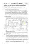
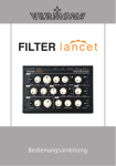
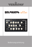
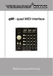
1
fourMulator - Owner's Manual
Owner's Manual VERMONA Retroverb Lancet
Introduction
Do you really need four LFO units in single module? Let's "fourMulate" it
like this: You cannot really have enough LFOs, can you? Even a classic
synthesizer easily offers four targets for LFO modulations. To name a
few: vibrato, pulse width, the filter's cutoff frequency and tremolo. In a
modular synthesizer there are even significantly more options. Now add
the options deriving from a combination of multiple LFOs to create interaction between the units to make these applications more thrilling.
We could have simply named this module Quad-LFO. However, this felt
too boring on the one hand and it wouldn't describe the fourMulator's
full feature-set on the other. Its four sync able, phase-variable and CVcontrollable LFOs are able to create trigger-sequences that can be varied
in real time thanks to a comfortable user interface. fourMulator acts as a
modulation- as well as clock-central and is capable of being your new
clock-reference for your modular synthesizer.
The VERMONA team
Erlbach/Vogtland, Germany
-2-
Owner's Manual VERMONA Retroverb Lancet
Important Safety Information
1.
Read these instructions.
2.
Keep these instructions. Alway include these instructions when passing the product on to third parties.
3.
Heed all warnings.
4.
Follow all instructions.
5.
Do not use this apparatus near water.
6.
Only clean the product when it is not connected to the mains power
supply. Clean only with a dry cloth.
7.
Do not block any ventilation openings. Install in accordance with
the manufacturer's instructions.
8.
Do not install near any heat sources such as radiators, heat registers, stoves, or other apparatus (including amplifiers) that produce
heat.
9.
Do not defeat the safety purpose of the polarized or groundingtype plug. A polarized plug has two blades and a third grounding
prong. The wide blade or the third prong are provided for your safety. If the provided plug does not fit into your outlet, consult an
electrician for replacement of the obsolete outlet.
10. Protect the power cord from being walked on or pinched, particularly at plugs, convenience receptacles, and the point where they
exit from the apparatus.
11. Only use attachments/accessories specified by the manufacturer.
12. Use only with the cart, stand, tripod, bracket, or table specified by
the manufacturer, or sold with the apparatus. When a cart is used,
use caution when moving the cart/apparatus combination to avoid
injury from tip-over.
13. Unplug this apparatus during lightning storms or when unused for
long periods of time.
14. Refer all servicing to qualified service personnel.Servicing is required when the apparatus has been damaged in any way, such as power supply cord or plug is damaged, liquid has been spilled or objects have fallen into the apparatus, when the apparatus has been
exposed to rain or moisture, does not operate normally, or has been
dropped.
15. To completely disconnect this apparatus from the AC mains,
disconnect the power supply cord plug from the AC receptacle.
16. WARNING: To reduce the risk of fire or electric shock, do not expose this apparatus to rain or moisture.
-3-
Owner's Manual VERMONA Retroverb Lancet
17. Do not expose this equipment to dripping or splashing and ensure
that no objects filled with liquids, such as vases, are placed on the
equipment.
18. The mains plug of the power supply cord shall remain readily accessible.
Installation
• Ensure that the room in which you use this product is wired in accordance with the local electrical code and checked by a qualified inspector.
• Only use this product indoors.
• Do not install the product in hot, humid, or excessively dusty locations, in direct sunlight or in locations where it is exposed to externally
generated vibrations.
• Do not place burning objects (e.g. candles) on top of or near the product.
• If condensation has formed on the product, e.g. because it was moved
from a cold environment to a warm one, allow the product to acclimatize to room temperature before using it.
• Do not overload wall outlets and extension cables as this may result in
fire and electric shock.
-4-
Owner's Manual VERMONA Retroverb Lancet
Table of Contents
1 Introduction ...................................................................................................2
2 Important Safety Information ...................................................................3
3 Table of Contents .........................................................................................5
4 Getting Startet ................................................................................................6
4.1. Setup .............................................................................................................6
5 A fourMulator – what is it? ........................................................................8
5.1. Technical data ............................................................................................8
6 Connections and Controls ..........................................................................9
6.1. Control elements of the four modulators ............................................9
6.2. Inputs and Outputs .................................................................................13
6.3. Control elements of the clock-generator (CLK) .................................13
6.4. Further connections ................................................................................14
7 Using the fourMulator ...............................................................................15
7.1. Reciprocal modulations .........................................................................15
7.2. Clock yourself ..........................................................................................16
7.3. Where to send the trigger-sequence? ..................................................16
7.4. Soft Edges..................................................................................................17
8 Technical Data.............................................................................................17
9 Declaration of Conformity .......................................................................18
-5-
Owner's Manual VERMONA Retroverb Lancet
Getting Startet
To ensure top quality, we carefully inspected the module before packaging. Nevertheless, the unit could have been damaged during transportation. Therefore, we ask you to take a serious look at the module when
unpacking. Do not hesitate to contact us, should there be anything
unusual with the unit or its packaging.
You should find the following items in the box:
• the fourMulator module
• a system bus connector cable (compatible to Doepfer's A100, TipTop
Audio Zeus and others)
• four rack screws 3x6mm
• four flat washers 3mm
• four patch chords (2x15cm, 2x30cm)
• this manual
Setup
The fourMulator was designed to work in modular synthesizer systems
using the common euro rack format. Its power supply, connectors and
dimensions match the specifications of Doepfer's A100 modular synthesizer system and compatible units. To mount the module into your system's frame, carry out the following steps:
1.
Switch off the power-supply. Safety first: Remove the detachable
power cable from your frame – it is possible that you accidentally
touch the internal power transformer.
2.
Connect the supplied ribbon-cable to the module's rear. The corresponding plug socket is protected against reverse polarity. The ribbon-cable will only fit in one direction.
3.
Connect the ribbon-cable's other side to an empty plug-socket of
your frame's system bus. Make sure the color coded side of the
cable points downwards (-12V)!
ATTENTION
Connecting the ribbon-cable with reverse polarity
can lead to damage of your module when powering the system!
-6-
Owner's Manual VERMONA Retroverb Lancet
fourMulator
system bus
ribbon cable
-12 V
Picture 1: Connecting the fourMulator to the system bus
4.
Mount the fourMulator to your modular frame. The unit requires a
width of 34 HP (horizontal pitch) and is rack-mounted with the four
supplied screws.
NOTE
5.
To protect the unit's surface of scratches, use
the supplied flat plastic washers.
Reconnect the power chord to your frame and switch on the powersupply. The module is now ready to work. The four green LEDs for
the four LFOs as well as both red clock LEDs will now blink according to the set tempo values.
Learn how to connect the different in- and outputs to the other modules
of your system in the next chapters of this manual.
-7-
Owner's Manual VERMONA Retroverb Lancet
A fourMulator – what is it?
Simply described, Vermona's fourMulator is a quadruple LFO, with all
LFO units (modulators) being able to run freely or synchronized to each
other. All four LFOs are equipped equally with one exception: LFO 1 can
only act as sync reference to the other three LFOs, while these may act as
sync reference or being synced to their left counterparts.
In addition, fourMulator offers a clock/trigger section. Using this, the
unit can be synced to other clock sources, e.g. an analogue sequencer, or
may act as a sync reference. Furthermore, the unit's user definable and
editable trigger-sequence is a perfect partner to a variety of gate dependent modules.
Technical data
The fourMulator has been designed to work with almost any available
module. For those with deeper interest, here are a few specifications for
newcomers and experts.
fourMulator outputs CV-voltages with a range between +5 and -5 volts, a
total range of 10 volts. Note that some modules are not designed to handle negative voltages. In this case, only the positive voltage will affect the
controlled function. There are also CV-inputs, e.g. for cutoff control of
certain filters, that work within a range of 0 to 10 volts. Although the
total range is identical, the fourMulator's LFOs cannot sweep the full
range. In these cases, using an offset generator is helpful, such as
Doepfer's A-183-2.
Triggers and clock impulses are output with 12 volts with positive slope
and 50ms duration. This specification is accepted by almost all available
modules that accept gate signals, e.g. envelopes, switches, reset-inputs
for LFOs, start/stop inputs for sequencers etc.
The reset and clock inputs accept signals ranging between 3,5 and 12
volts.
-8-
Owner's Manual VERMONA Retroverb Lancet
Connections and Controls
Picture 2: Controls and Connectors of the fourMulator
Control elements of the four modulators
The LFOs/modulators in the fourMulator are built identically. The corresponding identical functions are only described once, while the differences in synchronization and phase shift are described separately.
(1) WAVE selector
The six-stage WAVE knob selects the desired wave form. Available are
ascending saw tooth ( ), descending saw tooth ( ), square ( ), triangle ( ), sine ( ) and random (S/H = sample & hold).
NOTE
Switching between wave forms will not interrupt the amplitude. The wave form will not be
reset but directly take over the current value.
-9-
Owner's Manual VERMONA Retroverb Lancet
(2) SPEED- and SPEED/PHASE controls
The SPEED control adjusts the modulators' speed. SPEED covers a range
from approx. 0.05Hz to 100Hz. Therefore, modulations with audible frequencies are only possible within limits. The fourMulator's focus within
the sub audio range is intended because higher frequencies would not
make sense for use of the unit as clock-/trigger-generator or for reciprocal modulations.
For modulator 1, the SPEED control is limited to this function. For modulators 2, 3 and 4, this control can also shift the phase of the selected
wave form when being synchronized to the left neighboring unit (SYNC
switch set to left position, see "(3) SYNC-switch", page 11). Here, the LFO
being synchronized runs with the same speed as the reference LFO. Use
SPEED/PHASE to adjust the phase of the wave for the synchronized LFO
between 0° and 180°, shifting the wave form's start-point
Modulator 1
Modulator 2
180°
Picture 3: Phase Shift
SPEED and SPEED/PHASE offer a third control function. With SYNC set to
the CLK position (Clock), the controls set the clock division in respect to
the incoming clock signal. Find more details in "(3) SYNC-switch" on page
11.
The tempo is displayed using the corresponding LEDs for every SPEED
control. With every commencing new wave-form-cycle, the LED will be lit.
- 10 -
Owner's Manual VERMONA Retroverb Lancet
For modulators being synchronized and being shifted in phase, the LED
flash with the same tempo but with a corresponding delay.
(3) SYNC-switch
The SYNC switch offers three positions: OFF, SYNC and CLK (Clock).
NOTE
Modulator 1 only offers OFF and CLK positions since it can only be used as a sync reference but cannot be synchronized itself.
OFF
The modulator runs at the speed set with the corresponding SPEED
control.
SYNC (indicated by the numbers
,
and
)
The modulator is synchronized to its left counterpart. It follows the
clock-reference's speed. By this, multiple modulators can be varied in
frequency at once using the SPEED control of the modulator acting as
clock-reference. In sync-mode, SPEED controls the phase of the synchronized modulator (see "(2) SPEED- and SPEED/PHASE controls",
page 10).
NOTE
It is possible, to synchronize two or even three
modulators with modulator 1 by setting the
adjacent sections to sync. Also, modulators 1
and 2 as well as modulators 3 and 4 can be
used as independent synced pairs.
CLK
The modulator is either synchronized to an internal or external clock
signal (see chapter 2.3). Use SPEED- or SPEED/PHASE to select one of
eight available clock division settings, i.e. the modulators' speed will
only move within a clock related grid.
Neither the internal clock nor an external signal is predefined. A
clock can work with any resolution, e.g. with 4, 16 or 96 impulses per
- 11 -
Owner's Manual VERMONA Retroverb Lancet
bar. Therefore, the clock division needs to be regarded relatively to
this base.
With a clock signal based upon quarter impulses, the eight available
click divisions equal the following values (as indicated on the outer
ring of the control):
4
5
6
3
2
7
1
8
Picture 4: Clock Divider
1.
1/1 note =
a quarter of the speed of the incoming clock
2.
1/2 note =
half the speed of the incoming clock
3.
1/4 note =
the speed of the incoming clock
4.
1/4 triplet =
5.
1/8 note =
6.
1/8 triplet =
7.
1/16 note =
four times the speed of the incoming clock
8.
1/32 note =
eight times the speed of the incoming clock
twice the speed of the incoming clock
- 12 -
Owner's Manual VERMONA Retroverb Lancet
Inputs and Outputs
Each modulator offers four jacks to be connected to other modules.
(4) WAVE
This jack outputs the selected wave form. Connect this output to a CVinput of any module. Typical applications would be modulations of a filter's cutoff frequency, an oscillator's pulse width or an oscillator's pitch.
(5) TRIGGER
This jack outputs a trigger signal with the start of new wave form cycle,
allowing to trigger modules such as envelopes, electronic switches or
sequencers.
(6) CV
This input allows connecting a positive or negative control voltage (+5
volts to -5 volts) to modulate the modulator's frequency. With SYNC or
CLK being active for the respective modulator, this CV will modulate the
phase shift or the clock division. The control voltage is added respectively subtracted from the current SPEED/PHASE value. However, it is not
possible to exceed a frequency of approx. 100Hz.
(7) RESET
This input allows connecting a gate/trigger signal that immediate resets
the wave form to its start point. With the modulation speed matched to a
song tempo, sending reset commands every bar, allow to achieve long
term beat-synchronized modulations.
Control elements of the clock-generator (CLK)
The clock-generator allows synchronizing fourMulator to other clockdependent modules, such as step-sequencers. fourMulator can either
work as beat reference or follow an external reference in sync.
(8) TAP button
Use this button to set the tempo for fourMulator's internal clock. A
tempo change will occur after tapping the button four times. For predictable results, tap in a constant rhythm.
- 13 -
Owner's Manual VERMONA Retroverb Lancet
(9) Clock output (CLK OUT)
This jack outputs the clock signal. It can be connected to modules such
as step-sequencers, clock dividers or sequential switches.
(10) Clock input (CLK IN)
This jack allows feeding an external clock signal into the fourMulator.
With this input being used, the internal clock is automatically disconnected from the modulators. By setting the SYNC switch to CLK, the
external clock will be used.
NOTE
The internal clock remains. By removing the
cable from CLK IN, the internal clock regains
control using the previous tempo. This tempo
setting will only be lost when switching of or
powering down the system.
Further connections
(11) Trigger-sequence output (TRIG SEQ)
The trigger-sequence being available on this output is a deduction of the
trigger-signals of all synchronized modulators. At least one of the modulators 2, 3 or 4 needs to be externally synchronized for the triggersequence to be active. Modulator 1 can run freely or being set to CLK.
With multiple modulators being synchronized, the corresponding trigger-signals are combined with respect to the selected clock division factors. This might sound abstract, but is logic. Please consult the overview
in chapter 1.3 for help. Otherwise, the proof of the pudding is in the eating. Here, a little practice is more helpful than a detailed description.
(12) Global Reset-Input (RESET)
By using this input, all wave form of all modulators can be reset with a
single trigger/gate-signal. Note that each modulator that uses its dedicated reset-input will not be reflected by the global reset.
- 14 -
Owner's Manual VERMONA Retroverb Lancet
Using the fourMulator
fourMulator can act as a control- and clock-central. However, this only
makes sense in combination with other modules. The following sections
offer a few helpful suggestions for using the fourMulator.
Reciprocal modulations
LFOs run statically. This might be desirable for some applications, while
for others this behavior appears lifeless. Because of their ability to be
CV-controlled, the LFOs in the fourMulator can act more organic. To do
so, create a modulation between two modulators and vice versa, the so
called cross-modulation.
Use multiples to duplicate the wave outputs of both modulators. This is
necessary because you will need to address the modulation target (filter
frequency, pitch) as well as the other modulator. A multiple with two or
three separated sections is recommend (Doepfer A-180, Intellijel
Buffered Multiple, WMD Buffered Multiple).
Patch one output into an attenuator (dedicated modules: Doepfer
A-183-1, Intellijel TriAtt, Malekko 8NU8R or use simple VCAs/mixers).
The attenuators are necessary, to adjust the amount of cross-modulation. Now, patch the attenuator's output to the CV-input of the other
modulator:
WAVE 1 > Multiples 1 > Attenuator 1 > CV IN 2
WAVE 2 > Multiples 2 > Attenuator 2 > CV IN 1
Add another patch chord per modulator to connect the multiple-output
to the modulation target. The resulting modulation is more complex
than a common CV-controlled speed modulation that also runs
periodically.
Essential for this setup is the right amount of modulation depths and
the modulators' speed settings. (Note that the modulators must not be
synchronized). Start experimenting by using a triangle wave form. However, other wave forms also lead to interesting results.
The same setup can also be used, with either modulators or at least
modulator 2 being switched to CLK. Here, not the frequency but the
clock division (siehe "(3) SYNC-switch", Seite 11) is modulated. The
resulting modulation is not as complex but it will grant you with predictable rhythmic patterns instead.
- 15 -
Owner's Manual VERMONA Retroverb Lancet
fourMulator
Multiple
Attenuator
INT
IN
OUT
INT
IN
OUT
Picture 5: Patch Example - Crossmodulation
Clock yourself
fourMulator offers the possibility to enter the clock tempo using the TAP
button. However, continuous tempo changes using a control are still possible. To do so, simply connect the TRIGGER output of a modulator to
CLK IN. Now, the modulator serves as clock-reference where the speed
can be manually controlled using the corresponding SPEED knob. An
interesting option: The speed can be specifically modulated using the CV
input. Obviously, you may use another modulator to do so. However,
multiple CV-sources can serve for this application, such as Theremin
antennas, step-sequencers, envelopes etc.
Where to send the trigger-sequence?
The trigger-sequence is a unique feature of the fourMulator. But what is
it good for?
A simple application would be triggering a filter envelope, which no
longer triggered by keystrokes but with a certain rhythm.
Apart from that, the trigger-sequence can control all kinds of logic modules. Anywhere a straight clock-signal can be used, the trigger-sequence
can apply a rhythmic sequence of impulses to expand the receiving modules' possibilities.
Instead of patch examples, here is a list of modules that may be used
meaningful in combination with fourMulator:
• 4ms Pedals: Rotating Clock Divider, Shuffling Clock Multiplier
• Analogue Systems: RS150 Sequential Switch
- 16 -
Owner's Manual VERMONA Retroverb Lancet
• Doepfer: A-150/A-151/A-152 Switches, A-160 Clock Divider, A-161
Clock Sequencer
• Intellijel Designs: µStep-sequencer
• Make Noise: Brains
• The Harvest Man: Stillson Hammer
• ... as well as Drum/Percussion modules by MFB, Analogue Solutions,
Tip Top Audio, Cwejman
Soft Edges
Jumping value changes are typical for sample & hold modulations. In
some cases, these changes are too abrupt. Here, the use of a slew-limiter
(e.g. Doepfer A-170, Analogue Systems RS-350) can be a good corrective
when patched to the WAVE output. Value jumps are now attenuated and
with careful use, you can even achieve an organic sounding vibrato
sounding more natural than a typical sine wave LFO.
A slew-limiter is also useful in combination with square waves. It turns
the curve into a trapezoid wave form which is advantageous when creating tremolo effects.
Technical Data
• Dimensions: 3 rack units/ 34HP
• Power consumption: max. 100 mA
• Connections (3.5mm TS)
• WAVE OUT: -5 to +5 volts
• Trigger impulses (CLK OUT, TRIGGER): 50ms, 12V
• CV IN: -5 to +5 volts
• min. input voltage RESET: +4V
• Frequency range: 0,05 Hz - 100 Hz
- 17 -
Owner's Manual VERMONA Retroverb Lancet
Declaration of Conformity
We declare under our sole responsibility that this product is in conformity with the following standards or standardization documents in
attention of operation conditions and installation arrangements acc. to
operating manual:
EN61000-3-2, EN 61000-3-3, EN 55013, EN 55020, EN 60065 according to
the provisions of the regulations 2004/108/EG and 2006/95/EG.
HDB electronic GmbH
Badesteig 20
08265 Erlbach
GERMANY
Phone: +49 37422 40 27 0
Fax: +49 37422 40 27 29
Email: [email protected]
Web: http://www.vermona.com
- 18 -