1
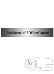
GV-HD-SDI Camera
GV-SDI-BX100 User’s Manual
Before attempting to connect or operate this product,
please read these instructions carefully and save this manual for future use.
© 2012 GeoVision, Inc. All rights reserved.
Under the copyright laws, this manual may not be copied, in whole or in part, without
the written consent of GeoVision.
104B
105B
Every effort has been made to ensure that the information in this manual is accurate.
GeoVision, Inc. makes no expressed or implied warranty of any kind and assumes no
responsibility for errors or omissions. No liability is assumed for incidental or
consequential damages arising from the use of the information or products contained
herein. Features and specifications are subject to change without notice.
106B
GeoVision, Inc.
9F, No. 246, Sec. 1, Neihu Rd.,
Neihu District, Taipei, Taiwan
Tel: +886-2-8797-8377
Fax: +886-2-8797-8335
http://www.geovision.com.tw
107B
108B
109B
10B
1B
12B0H
Trademarks used in this manual: GeoVision, the GeoVision logo and GV series
products are trademarks of GeoVision, Inc. Windows and Windows XP are registered
13B
trademarks of Microsoft Corporation.
July 2012
14B
Contents
1. SAFETY PRECAUTIONS AND INSTALLATION CONSIDERATION......................... 2
2. INTRODUCTION ............................................................................................... 5
3. FEATURES ....................................................................................................... 6
4. PACKING LIST................................................................................................... 8
5. NAME AND FUNCTION OF EACH PART ........................................................... 9
5.1 FRONT VIEW............................................................................................... 9
5.2 REAR VIEW................................................................................................11
6. INSTALLATION ................................................................................................ 13
6.1 LENS TYPE ............................................................................................... 13
6.2 USING AUTO IRIS LENS........................................................................... 13
6.3 USING A C/CS-MOUNT LENS................................................................... 14
6.3.1 INSTALLING A CS MOUNT LENS ................................................................. 14
6.4 CONNECT TO MONITOR.......................................................................... 16
6.5 CONNECT THE POWER........................................................................... 16
6.6 CONNECTION LAYOUT ............................................................................ 17
6.6.1 CONNECTING THE KEYBOARD................................................................... 17
6.6.2 CONNECTING THE IR ILLUMINATOR .......................................................... 19
7. OPERATION..................................................................................................... 23
7.1 PELCO KEYBOARD (OR COMPATIBLE) OPERATION ............................ 23
8. SYSTEM SETUP .............................................................................................. 24
8.1 OSD (ON SCREEN DISPLAY)................................................................... 24
8.2 SUB MENU DESCRIPTION....................................................................... 25
8.2.1 CAMERA SETUP............................................................................................ 25
8.2.2 EXPOSURE SETUP ....................................................................................... 25
8.2.3 DAY/NIGHT SETUP ........................................................................................ 26
8.2.4 WHITE BALANCE SETUP ............................................................................. 27
8.2.5 EFFECT SETUP ............................................................................................. 28
8.2.6 PRIVACY MASK SETUP ................................................................................ 28
8.2.7 DISPLAY INFO SETUP................................................................................... 30
8.2.8 COMMUNICATION SETUP ............................................................................ 32
8.2.9 DEFAULT SETUP ........................................................................................... 32
9. SPECIFICATIONS .......................................................................................... 33
1
2
1
Safety Precautions
1. Safety Precautions and Installation
Consideration
CAUTION
RISK OF ELECTRIC SHOCK.
DO NOT OPEN!
CAUTION :
TO REDUCE THE RISK OF ELECTRICAL SHOCK,
DO NOT OPEN COVERS (OR BACK).
NO USER SERVICEABLE PARTS INSIDE.
REFER SERVICING TO QUALIFIED
SERVICE PERSONNEL.
It is advised to read the Safety Precaution Guide through carefully before
operating the product, to prevent any possible danger.
WARNING: Alert the user to the presence of un-insulated “dangerous voltage”.
CAUTION: Alert the user the presence of important operating and maintenance
(Servicing) instructions in the literature accompanying the appliance.
Disposal of Old Electrical & Electronic Equipment (Applicable in the
European Union and other European countries with separate collection
systems).
This symbol indicates that this product shall not be treated as household waste.
Instead it shall be handed over to the applicable collection point for the recycling of
electrical and electronic equipment. By ensuring this product is disposed of correctly,
you will help prevent potential negative consequences for the environment and human
health. For more detailed information about recycling of this product, please contact
your local city office, your household waste disposal service or the shop where you
purchased the product.
Please be extra careful not to shake the product.
Please avoid places where frequent vibrations or shocks.
Do not install the product in extreme temperature conditions.
Only use the camera under conditions where temperatures are between -10℃ and +60℃. Be
especially careful to provide ventilation when operating under high temperatures.
3
Do not install the product in an environment where the humidity is high.
Unless the product is waterproof or weatherproof, otherwise it can cause the image quality to
be poor.
Do not expose to strong light (sun rays), as color filters will be discolored.
Do not spill liquid of any kind on the product.
If it gets wet, wipe it dry immediately. Alcohol or beverage can contain minerals that corrode
the electronic components.
When any abnormal occurs, make sure to unplug the unit, and contact your local dealer.
Installation Consideration:
It is recommended to use RG-59 cable, with the maximum cable distance of 100
meters, to maintain a stable signal.
4
2
Introduction
2. Introduction
This HD-SDI digital image camera uses a high sensitive color Sony 1/2.8” interline
transfer Charge Coupled Device (CMOS) image sensor, producing pictures reaching
up 900 lines of horizontal resolution.
Super ATR-EX technology can achieve the WDR application through the normal
image sensor. The camera-side initiatively provides mobile detection warnings
offering more comprehensive monitoring of safety protection. Carefully planned
privacy zone enables monitoring more at ease.
There are two models of cameras:
Model No.
Lens
Description
GV-SDI-BX100-0
Varifocal
2 MP, D/N, Auto Iris
GV-SDI-BX100-1
Fixed
2 MP, D/N, Fixed Iris
5
3. Features
High Resolution
CMOS Sensor provides high resolution
reaching up 900 TVL with advanced
and clear picture quality.
Excellent Sensitivity
High sensitivity, low smear, high
anti-blooming and high S/N ratio
ATR-EX (WDR)
High-quality ATR-EX (Augmenting Tone
Reproduction) or WDR (Wide Dynamic
Range). Functions perfectly show the
Digital Noise Reduction (DNR)
2D DNR, realize the clear image at low
light environment, clear picture quality
saving hard disk storage size of DVR.
image details between dark and light.
Newly added environment dynamic
detection switch, enhancing image
efficiency.
6
Day & Night
Mechanic IR cut-filter driving unit with
AE provides change from color to B&W
mode automatically for day and night
24-hour surveillance. Selectable
between manual Day & Night control
or from external input signal Day &
Night control.
Resolution Support
Support 12 types of resolution and
Auto switch image output.
1080P60 ,1080P50 ,1080I60 ,
1080I50, 1080P30, 1080P25 ,
1080P59.94 , 1080P29.97 ,
1080I59.94 ,720P60, 720P50 ,
720P59.94.
Privacy Mask
Privacy image masking with free
position supports up to 16 privacy
mask areas.
RS485 / RS422 Function
Support PELCO P/D protocol ,
RS485 / RS422 function output.
3
Features
Lens (C/CS Mount)
Support the auto-iris lens by DC type
(DC-Drive) or fixed iris lens.
Extra Connection
Control the camera easily by
keyboard/PT Driver via RS485
interface.
OSD
OSD (On Screen Display) Setup Menu.
Camera title setup of up to 16
alphanumeric letters.
Image Control
Performance: positive/ negative
image, mirror function (left/ right),
reverse turn (up/ down), and 180°
rotation.
Hotkey (Factory Default)
Press Up button for approximately 10
seconds after power-on, the camera will
be reset to its factory settings.
Application
All functions can be operated from
OSD: AES (Automatic Electronic
Shutter), AI (Auto Iris), GC (Gain
Control), WB (White Balance) and BLC
(Back Light compensation).
7
4. Packing List
Check and make sure all the items shown below are included in your product
package. If something is missing, contact your dealer as soon as possible.
1.
GV-HD-SDI Camera (with Varifocal or Fixed Megapixel Lens)
2.
DC 12V Power Adapter
3.
Accessories
•
Screw x 2
•
Mounting Tripod Base x 1
•
L-wrench x 1
4. User’s Manual
8
5
Name and Function of Each Part
5. Name and Function of Each Part
5.1 Front View
GV-SDI-BX100-0 (Varifocal Lens)
2
1
1
○
2
○
3
○
4
○
3
4
Focus Screw
Adjusts the focus of the camera.
Zoom Screw
Adjusts the zoom of the camera.
Auto Iris Connector
Plug the iris control cable to the connector.
Mounting Tripod Base
Mounting base for installing the camera.
9
GV-SDI-BX100-1 (Fixed Lens)
2
1
3
1
○
2
○
3
○
10
Focus Screw
Adjusts the focus of the camera.
Auto Iris Connector
Not functional.
Mounting Tripod Base
Mounting base for installing the camera.
5
Name and Function of Each Part
5.2 Rear View
Sends video signal (HD-SDI) and connects to the
video input terminal of the monitor.
1
○
Video-Out terminal:
2
○
Function Input/ Output and RS-485 Interface
(Protocol: AUTO/ NATIVE/ PELCO/ LG. Speed: 2.4K/ 4.8K/ 9.6K/ 115.2K BPS)
3
○
No.
Name
Function
1
DNI
External Day/ Night input
2
GND
Ground
3
DNO
Day/ Night output
4
GND
Ground
5
D+ R+
RS-422/ RS-485 Interface R+
6
D- R-
RS-422/ RS-485 Interface R-
7
T+
RS-422/ RS-485 Interface T+
8
T-
RS-422 RS-485 Interface T-
Power LED:
This lamp is lit when the camera is receiving power
normally.
11
4
○
OSD Button:
No.
Name
Function
1
S
Up (S)
2
T
Down (T)
3
(+)/►
Increase Value (+)
4
(-)/◄
Decrease Value (-)
5
Menu
Enter or Exit Setup Menu
• Up button:
Used to move cursor up in the menu screen and to
zoom-in.
<Note>
Press Up button for approximately 10 seconds after
power-on, the camera will be reset to its factory
settings.
5
○
12
• Down button:
Used to move cursor down in the menu screen and to
zoom-out.
• Right button:
Used to move the cursor right in the menu screen and to
increase a setup value.
• Left button:
Used to move the cursor left in the menu screen and to
decrease a setup value.
• Menu Button:
Displays the menu on the screen and to enter or exit the
selection.
Power input
terminal:
Connects to the appropriate power.
6
Installation
6. Installation
6.1 Lens Type
The camera is supplied with a CS-mount lens. You could refer to the below steps
only when changing lenses.
6.2 Using Auto Iris Lens
Fit the cover of the auto iris connector plug, remove the protective glass cover from
the front of the camera, and fasten the auto iris lens by turning it clockwise.
Auto Iris PIN definitions
Pin
VIDEO DRIVER
DC DRIVER
(Direct DRIVE)
1
2
3
4
VDC OUT
IRIS OUT
N.C.
GND
DAMPDAMP+
DRIVE+
DRIVE-
1. Fit the cover of the auto iris lens connector plug, remove the protective glass cover
from the front of the camera, and fasten the auto iris lens by turning it clockwise.
13
3. When a lens is mounted, adjustment of the back-focus may sometimes be
required. Adjust the lens focus ring when the correct focus cannot be obtained.
Back Focus Adjustment
(1) Fully open the aperture and set the focus ring to “⎟” (infinity).
(2) Loosen the two back-focus screws with L-wrench, and turn the lens mount to
focus.
(3) After adjusting the back-focus, tighten the back-focus screw.
6.3 Using a C/CS-Mount Lens
You can optionally change the lens on the camera. Before installing a lens, identify
the lens type first. (C-Mount or CS-Mount.)
6.3.1 Installing a CS Mount Lens
Remove the installed lens on the camera, and turn the CS-Mount Lens clockwise to
install it. And set focus of the camera by loosening the two back-focus screw with an
L-wrench.
14
6
Installation
6.3.2 Installing a C Mount Lens
Remove the installed lens on the camera, and turn the C-Mount Lens clockwise to
install it. And set focus of the camera by loosening the two back-focus screw with an
L-wrench.
<Note>
• C-mount adapter is not supplied with the camera.
• Use the lens connector shown in the following figure. If the dimensions of the
connector are incorrect, it may damage the camera, or the lens may not be
installed firmly.
15
6.4 Connect to Monitor
Connect the Video-out (HD-SDI) port on the rear panel of the camera to a monitor. As
the connecting method varies depending on the instrument, therefore refer to the
manual supplied with the instrument for more information.
6.5 Connect the Power
Since the camera supports both AC and DC, you may connect an AC 24V, 1000mA
adaptor or a DC 12V, 1000mA adaptor. There is no positive (+) and negative (-)
difference for the two power connectors.
16
6
Installation
6.6 Connection Layout
To connect the keyboard and IR illuminator, follow the instructions shown below:
Connecting the IR illuminator
6.6.1 Connecting the Keyboard
17
PELCO Keyboard (or compatible) Installation
RS-422 interface is used for communicating PELCO keyboard. Refer to Fig. 1;
connect R+ of the camera to T+ of the PELCO keyboard. Connect R- of the camera
to T- of the PELCO keyboard.
User could adjust Camera ID via rear panel keys or via remote commands. Protocol,
Speed and Parity should only be adjusted via rear panel keys.
Communication
CAMERA ID
Setting
1 ~ 255 for P protocol
1 ~ 255 for D protocol
PROTOCOL
PELCO
SPEED
2400, 4800, 9600, 115200
PARITY
NONE
The speed of camera should be the same as the speed of the keyboard. Adjusted
function is only effective, after exiting the OSD setup menu.
<Note>
• Maximum cable distance for RS-485 communication over 24-gauge wire is 4,000
feet (1,219 m). Recommend using shielded twisted pair cable that meets the
basic requirements for EIA RS-485 applications.
Fig.1
18
6
Installation
6.6.2 Connecting the IR Illuminator
IR Illuminator
(Light Sensor)
Camera
IR Illuminator
(Camera Control)
<Note>
• The camera supports GV-IR LED T2, but it does not support GV-IR LED.
GV-IR LED T2 Installation
1.
Connect DNO of the camera with the yellow wire of GV-IR LED T2, and
connect GND of the camera with the green wire of GV-IR LED T2.
GV-IR LED T2
Green
Yellow
19
2.
Twist the red wire from the GV-IR LED T2 to the power cable (DC 12 V) from
the power adapter, which has the gray stripes on it, and twist the black wire from
the GV-IR LED T2 to the power cable (ground) from the power adapter, which has
the characters on it.
2 2 A W G X 2 C
Power Cable (DC 12 V)
3 0 0 V
Red Wire from the
GV-IR LED T2
Black Wire from the
GV-IR LED T2
Power Cable (ground)
3.
Connect the wires from step 2 to the power connectors on the camera.
4.
On the OSD menu, select Camera Setup and set Day/Night Mode to AUTO
(default value). Then select Camera Setup and set DI/DO to DI/H : DO/L or
DI/L : DO/L (both selections are okay).
20
6
Installation
Light Sensor Installation
1.
Connect DNI and GND of the camera to the DNI and GND of the IR illuminator
(with light sensor).
2.
3.
On the OSD menu, select Camera Setup and set Day/Night Mode to EXT.
If the operating IR illuminator (with light sensor) is of high voltage (5 V), select
4.
Camera Setup and set DI/DO to DI/H : DO/L or DI/H : DO/H (both selections are
okay).
If the operating IR illuminator (with light sensor) is of low voltage (0 V), select
5.
Camera Setup and set DI/DO to DI/L : DO/L or DI/L : DO/H (both selections are
okay).
If the IR illuminator (with light sensor) works in conjunction with the IR illuminator
(of camera control), in which the light sensor will trigger the camera and then the
camera will trigger the IR illuminator, you need to set up DI/DO on the OSD menu
based on the operating voltage of the devices:
•
•
•
•
The operating IR illuminator (with light sensor) of high voltage (5 V) + the
operating IR illuminator (of camera control) of high voltage (5 V): select
Camera Setup and set DI/DO to DI/H : DO/H.
The operating IR illuminator (with light sensor) of high voltage (5 V) + the
operating IR illuminator (of camera control) of low voltage (0 V): select
Camera Setup and set DI/DO to DI/H : DO/L.
The operating IR illuminator (with light sensor) of low voltage (0 V) + the
operating IR illuminator (of camera control) of high voltage (5 V): select
Camera Setup and set DI/DO to DI/L : DO/H.
The operating IR illuminator (with light sensor) of low voltage (5 V) + the
operating IR illuminator (of camera control) of low voltage (0V): select
Camera Setup and set DI/DO to DI/H : DO/L.
For the OSD settings, see 8.2.3 DAY/NIGHT Setup and 8.2 Sub Menu Description.
21
IR Illuminator Installation
1. Connect DNI and GND of the camera to the DNI and GND of the IR Illuminator (of
camera control).
2.
To automatically switching between night and day modes:
•
If the operating IR illuminator (of camera control) is of high voltage (5 V), on
the OSD menu, select Camera Setup and set Day/Night Mode to AUTO
(default value). Then select Camera Setup and set DI/DO to DI/H : DO/L or
DI/L : DO/L (both selections are okay).
•
3.
If the operating IR illuminator (of camera control) is of low voltage (0 V), on
the OSD menu, select Camera Setup and set Day/Night Mode to AUTO
(default value). Then select Camera Setup and set DI/DO to DI/H : DO/H or
DI/L : DO/H (both selections are okay).
To remain the camera on the night mode,
•
If the operating IR illuminator (of camera control) is of high voltage (5 V), on
the OSD menu, select Camera Setup and set Day/Night Mode to NIGHT.
Then select Camera Setup and set DI/DO to DI/H : DO/H or DI/L : DO/H
(both selections are okay)..
•
4.
If the operating IR illuminator (of camera control) is of low voltage (0 V), on
the OSD menu, select Camera Setup and set Day/Night Mode to NIGHT.
Then select Camera Setup and set DI/DO to DI/H : DO/L or DI/L : DO/L
(both selections are okay).
To have the IR illuminator (with light sensor) working with the IR illuminator (of
Camera Control) together, see Step 5 of Light Sensor Installation mentioned
earlier.
For the OSD settings, see 8.2.3 DAY/NIGHT Setup and 8.2 Sub Menu Description.
22
7
Operation
7. Operation
1.
2.
3.
Mount the camera on the mounting bracket by using the hole on the top or bottom
of the camera, and by using the enclosed mounting block, secured by 2 screws.
Connect the video output to the monitor or other video device via a 75 Ohms type
coaxial cable.
Power Input Terminal (Dual Power): the camera accepts both AC 24V and DC 12 V
power sources (non-polarity).
7.1 PELCO Keyboard (or compatible) Operation
OSD Setup Menu Mode
PELCO Keyboard
Camera Function
OPEN
Sub Menu Enter
CLOSE
Sub Menu Exit
Move Joystick Left
Decrease (-)
Move Joystick Right
Increase (+)
Move Joystick Up
Cursor Up
Move Joystick Down
Cursor Down
Connecting PELCO keyboard with the camera:
1. Find the DIP switch at keyboard back panel and press down No. 5, 6, and 7 to
meet the required speed (2400).
2.
3.
4.
Press buttons 0, 1 and CAM on the keyboard to set the camera ID.
Press buttons 9, 5 and PRESET for startup.
Press OPEN button to show the OSD menu for further camera control.
<Note>
• Refer to PELCO Keyboard manual for more information.
23
8. System Setup
8.1 OSD (On Screen Display)
Main Menu Display
MAIN MENU
V1.00 2012-04-03
PROFILE
CAMERA SETUP
PRIVACY MASK
DISPLAY INFO
COMMUNICATION
SYSTEM INFO
DEFAULT
STANDARD
─
─
─
─
─
ON
Main Menu Setup
In order to display the setup menu on the screen, set the menu command or
press the button panel.
• Use S/ T control buttons to select each item.
• Use ◄(-)/ ►(+) control buttons to change the data.
•
•
Use MENU control button to ENTER/ EXIT the menu display.
<Note>
• The default option will set all the configuration settings to factory default values.
24
8
System Setup
8.2 Sub Menu Description
CAMERA SETUP
LENS
DI/DO
EXPOSURE
DAY/NIGHT
WHITE BALANCE
EFFET
RETURN
DC
DI/L : DO/H
─
─
─
─
ON
8.2.1 CAMERA Setup
The box camera supports both DC-type and Manual-type lenses. DC-type lens
application is suggested for best quality and performance.
8.2.2 EXPOSURE Setup
EXPOSURE
ATR-EX
LEVEL
SHUTTER
BLC
AGC
DNR
DEFAULT
RETURN
NORMAL
NA
AUTO
OFF
HIGH
OFF
ON
1.
There are two types of modes: NORMAL / ATR-EX
2.
Level 0~4 step (ATR-EX default: 3 ). The larger the value, the larger the image
efficiency.
3.
SHUTTER consists of the following types :
AUTO ,1/50 ,1/60 , 1/90, 1/100(FLK) ,1/120(FLK) ,1/180 , 1/250, 1/350 ,
1/500,1/725, 1/1000, 1/1500,1/2000 ,1/2500 ,1/4000 ,1/5000 , 1/10000 ,1/20000
(Default Setup: AUTO).
25
<Note>
• When images appear fuzzy, select 1/60 for the country of NTSC (60 Hz) and
1/50 for the country of PAL (50 Hz).
4.
BLC ON/OFF (Default Setup: OFF).
5.
AGC modes: OFF / LOW / MID / MID.HIGH / HIGHT
6.
DNR Level: OFF / 1~5 step. Enable / Disable 2DDigital Noise Reduction function
(Default Setup: OFF).
7.
DEFAULT: Return to exposure default setup.
8.
RETURN: Return to previous status.
8.2.3 DAY/NIGHT Setup
DAY/NIGHT
MODE
DAY TO NIGHT
NIGHT TO DAY
DELAY TIME
B/W
DEFAULT
RETURN
AUTO
148
73
5
OFF
ON
VALUE 2074
D2N 3996
N2D 1971
1. There are four types of modes: AUTO/ DAY/ NIGHT/ EXT (Default Setup: AUTO).
(1) AUTO: According to DAY→NIGHT and NIGHT→DAY (Threshold Value), it will
auto switch to Color or B/ W.
(2) DAY: Fixed to Color mode.
(3) NIGHT: Fixed to B/ W mode.
(4) EXT: When Day & Night mode is set to “External” on the camera OSD menu, this
function will switch according to the IR Illuminator (light sensor). For more
information, refer to the back panel function (Input Pin [DNI]).
2. DAY→NIGHT: The threshold value of color change (from color to B/ W) under AE
mode. Switches to B/W when “D2N “≦ “VALUE”.
3. NIGHT→DAY: The threshold value of color change (from B/ W to color) under AE
mode. Switches to Color when “N2D“≧ “VALUE”.
4. DELAY TIME: Adjust the level from 1 to 60 seconds.
26
8
System Setup
5. B/W: Set to ON for B/W images and OFF for Color images.
6. DEFAULT: Return to day/night default setup.
7. RETURN: Return to previous status.
<Note>
• When D/N are set to AUTO, the value will be automatically adjusted regarding
to the circumstances.
• Using DC LENS from different manufacturers may result in switching
problems (unable to switch), you could adjust and operate according to
current environment (adjust DAY-NIGHT or NIGHT-DAY value in order to meet
the current environment).
• Day Night ambiguity suppression:
Because the ICR filter of the camera switches according to the illumination
environment. The system in order to avoid the occurrence of ICR hunting issue,
as in some special environments, the Day/Night function may keep on switching
the ICR filter. If the ICR keeps on switching for over three times, the camera will
disable the Day/Night detection function. And the Day/Night detection function will
return to Auto after 30 min.
8.2.4 WHITE BALANCE Setup
WHITE BALANCE
WB MODE
RED GAIN
BLUE GAIN
PUSH AUTO
DEFAULT
RETURN
AWB
NA
NA
NA
ON
1. WB MODE: Five types of mode: AWB, ATW, INDOOR, OUTDOOR, PUSH AUTO,
and MANUAL (Default Setup: AWB).
2. RED GAIN/ BLUE GAIN operate only when WB MODE is set to MANUAL,
otherwise it is NA (Not Available).
3. When WB MODE is set to PUSH AUTO:
(1)
(2)
PUSH AUTO ON: Enable auto tracing white balance.
PUSH AUTO OFF: Depending on environment, disable auto tracing white
balance and record the current white balance value.
4. DEFAULT: Return to white balance default setup.
5. RETURN: Return to previous status.
27
8.2.5 EFFECT Setup
EFFECT
POSI/NEGA
MIRROR
DEFAULT
RETURN
POSI
OFF
ON
1. POSI/ NEGA: Images can be set to POSI (Positive Image) or NEGA (Negative Image).
(Default Setup: POSI).
2. Four Types of MIRROR Mode: OFF/ HORIZONTAL/ VERTICAL/ ROTATE (Default
Setup: OFF).
3. DEFAULT: Return to effect default setup.
4. RETURN: Return to previous status.
8.2.6 PRIVACY MASK Setup
PRIVACY MASK
AREA
MASK
START X
END X
START Y
END Y
COLOR
TRANSP
MOSAIC
DEFAULT
RETURN
1
ON
16
156
12
84
WHITE
2
ON
ON
1. AREA: Maximum PRIVACY MASK area setting is 16 (Default Setup: 1).
28
1
5
9
13
2
6
10
14
3
7
11
15
4
8
12
16
8
System Setup
2. MASK: Set MASK to “ON”, MASK AREA becomes available for setup and is shown on
the monitor (Default Setup: OFF).
3. START X: Horizontal start position (0~600).
4. END X: Horizontal end position (40~640).
5. START Y: Vertical start position (0~330).
6. END Y: Vertical end position (30~360).
7. COLOR:WHITE , BLACK , RED , GREEN , BLUE , YELLOW , CYAN,
8. MAGENTA.
9. TRANSP : Transparency level (0~3).
10. MOSAIC : Mosaics ON/OFF.
11. DEFAULT: Return to privacy mask default setup.
12. RETURN: Return to previous status.
<Note>
• When privacy mask has been enabled the motion area that has been covered by
the privacy mask becomes ineffective.
29
8.2.7 DISPLAY INFO Setup
DISPLAY INFO
DISPLAY
COLOR
RESOLUTION
RETURN
─
─
1080P30
1. DISPLAY: Under this item user may decide whether to reveal or hide TITLE SET /
TITLE DISPLAY / TITLE POSITION / ID DISPLAY / ID POSITION. For more setup
details on display, follow the setup guide shown below:
DISPLAY
TITLE
~~~~~~~~~~~~~~~~~
TITLE DISPLAY
TITLE POSITION
ID DISPPLAY
ID POSITION
~~~~~~~~~~~~~~~~~
OFF
LEFT UP
OFF
LEFT UP
DEFAULT
RETURN
ON
(1) TITLE: You can enter up to 16 characters.
_ −
0 1 2 3 4 5
A
B
C
D
E
F
G
H
I
P
Q
R
S
T
U
V
W X
6
7
8
9
J
K
L
M
Y
Z
N
(2) TITLE DISP: To reveal or hide title display, setup ON/ OFF.
(3) Four TITLE Setup Positions (TITLE/ ID):
RIGHT DOWN/ LEFT UP/ RIGHT UP/ LEFT DOWN
(Default Setup: LEFT UP).
(4) Four ID Setup Positions:
RIGHT DOWN/ LEFT UP/ RIGHT UP/ LEFT DOWN (Default Setup:
LEFT UP).
(5) DEFAULT: Return to display default setup.
(6) RETURN: Return to previous status.
30
O
8
System Setup
2. COLOR Setup:
COLOR
BRIGHTNESS
CONTRAST
SHARPNESS
HUE
GAMMA
DEFAULT
RETURN
0
128
64
0
2
ON
(1) BRIGHTNESS: Video brightness level setup (0~255).
(2) CONTRAST: Video contrast level setup (0~255).
(3) SHARPNESS: Video sharpness level setup (0~255).
(4) HUE: Video hue level setup (0~255).
(5) GAMMA: Video gamma setup (0~3).
(6) DEFAULT: Return to color default setup.
(7) RETURN: Return to previous status.
3. RESOLUTION Setup:
There are 12 types of modes: 1080P60 , 1080P50 , 1080I60 , 1080I50 , 1080P30 ,
1080P25 , 1080P59.94 , 1080P29,97 , 1080I59.94 , 720P60, 720P50 , 720P59.94 ,
(Default Setup: 1080P30 ).
4. RETURN: Return to previous status.
31
8.2.8 COMMUNICATION Setup
COMMUNICATION
CAMERA ID
SPEED
DEFAULT
RETURN
1
2400
ON
1. CAMERA ID: ID setup 0~255 (Default Setup: 1).
2. SPEED: Baud Rate setup 2400, 4800 , 9600 , 115200 (Default Setup: 2400).
3. Refer to “6. INSTALLATION” for more information on Communication.
8.2.9 DEFAULT Setup
MAIN MENU
PROFILE
CAMERA SETUP
PRIVACY MASK
DISPLAY INFO
COMMUNICATION
SYSTEM INFO
DEFAULT
V1.00 2012-04-03
STANDARD
─
─
─
─
─
ON
Select Default Settings and the system will return to its factory default settings. All
user settings on the device will be erased.
32
9
Specifications
9. Specifications
509B
Camera
GV-SDI-BX100-0
Image Sensor
1/2.8” type CMOS
Picture Elements
1920 (H) x 1080 (V)
Min.
Illumination
GV-SDI-BX100-1
Color
0.5 Lux at F/1.4
0.5 Lux at F/1.5
B/W
0.1 Lux at F/1.4
0.1 Lux at F/1.5
IR On
0 Lux
Resolution
Up to 900 TVL
Shutter Speed
Automatic / Manual (1/50 ~ 1/20,000 sec)
White Balance
AWB / ATW / Indoor / Outdoor / Push Auto / Manual
S/N Ratio
More than 50dB
Day/Night
Auto / Day / Night / EXT (with removable IR-cut filter)
BLC
On / Off
ATR-EX ( WDR )
On / Off (Auto detection , 5 Levels)
Digital Noise Reduction
Off / 1~5 Steps
Gain Control
Auto / Off / Low / Mid / Mid-H / High
Lens
Megapixel
Yes
Lens Type
Varifocal
Fixed
Focal Length
2.8 ~ 12 mm
4.0 mm
Maximum Aperture
F/1.4
F/1.5
Mount
CS Mount
Image Format
1/3”
Operation
Camera Title
1080P60, 1080P50, 1080I60, 1080I50, 1080P30, 1080P25,
1080P59.94 , 1080I59.94 , 1080P29.97, 720P60 , 720P50 ,
720P59.94
Up to 16 characters
Mirror
Off / Horizontal / Vertical / Rotation
Privacy Masking
16 areas (Area size adjustable)
Positive / Negative
On / Off
Signal System Format
33
General
Operating Temperature
-10℃~ 60℃ / 14℉~ 140℉
Power Source
DC12V / AC24V
Max. Power
Consumption
6.6 W
Video Output
3G HD-SDI / 800mV / 75 Ohms
Remote Control
RS-485 / RS-422
Protocol
PELCO D&P
All specifications are subject to change without notice.
34
9
Specifications
35
The GeoVision logo and GV series products are trademarks of GeoVision, Inc.
© 2012 GeoVision, Inc. All rights reserved.
All GeoVision Products are manufactured in Taiwan.
2012/07
English
SDIBX100-B-EN