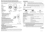
1
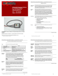
SSEB (Solid State Exhaust Brake)- Solid State Exhaust Brake with Optional Programmable
Speed Sense Torque Converter Lockup. Also for Standalone SSTCC Controller.
Installation Directions & User Manual
Please read entire document before beginning installation and use
SP Diesel Performance. All Rights Reserved. Copyright 2005.
Page 1
SP Diesel Performance Products
SP Diesel Performance Solid State Exhaust Brake (continued)
Thanks for
your
purchase!
The staff at SP Diesel Performance thanks you for your recent purchase of
the SP Diesel Performance Solid State Exhaust Brake with Optional
Programmable Torque Converter Lockup Module. This brake represents a
year of research and development to improve an existing best selling
product. We consider it to be the most advanced electronic exhaust brake
on the market for the 7.3L PowerStroke Diesel engine. We are sure you will
find all SP products to be an exceptional value for your dollar. We have
designed all SP products to be easy to install, while offering you the same or
nearly the same results of similar, higher dollar products.
Before you
begin
Before you begin installation you should make sure you have at least a basic
understanding of tools and items in and around your engine bay. You don’t
need to be an expert with our instructions but, if you aren’t comfortable, try
and find a knowledgeable friend there to lend support, or if all else fails we
are available by email and phone. We recommend email as the quickest way
to get help. On a scale of technical difficulty, installation of the SP
Performance SSEB Kit is a 3 on a scale of 10 (10 being the highest). Also as
with any modification to your truck, remove the key from the ignition.
Pictures may be supplied at the end so you can print them out and keep
them next to the text directions for easy reference. All picture references will
be noted in the instructions.
Read
Directions
Completely
Please read all directions applicable to your installation prior to beginning
installation. You may have a better sense of the install by reading this
document prior to embarking on your installation.
Parts List
See the below chart for a complete list of parts. Optional parts are noted as
such in the list.
•
•
•
Tools List
1 SP Diesel SSEB/SSEBTC/SSTCC
SP Diesel SS Series Harnesses
Parts kit
See the below chart of tools recommended for installation.
Tool
Long-Nose Pliers
Screwdriver
Zip Ties
Wire Cutter Crimper
Purpose
Used for making tap splices
Used for securing terminal strip positions.
Used for neatening up your install
Used for tap splices, cutting wire, and stripping
wire.
Continued on next page
SP Diesel Performance. All Rights Reserved. Copyright 2005.
Page 2
SP Diesel Performance Products
SP Diesel Performance Solid State Exhaust Brake (continued)
Pop the dash
panel cover,
take a gander
Pop the dash panel of your truck and take a look at the driver’s side of the
truck, and familiarize yourself with the area just under the steering column.
This is where your install will take place.
Wire Color
and
Positions
Use the below chart to reference the wire colors and positions on the SSEB
as they relate to the wires you need to tap or make connections to. Please
note there is an 8 way and a 6 way connector on the left side of the box. DO
NOT under any circumstances attempt to plug into the port on the right side.
You will likely damage the products circuitry. Also be sure to pay close
attention to the wire colors in each harness. There are some duplicate colors
and therefore, you need to ensure where you are connecting. Some
connections may not be used, as shown in the chart below, we recommend
coiling the wires up and zip-tie them away for later use. The SSEB is a multifunctional design and those wires may be used at a later date, should the
unit be reprogrammed or re-purposed.
Connector
Harness
Position
Markings
The harnesses used in the SSEB have markings on the connector housings.
These markings indicate the first position (1) and the last position (8/6).
Please remember this when referring to the chart on the next page.
Pay attention
to your
configuration
The SS Series Controllers are sold as a brake only, brake with TC, and TC
only flavors. Make sure you only attempt to make the connections
necessary. The unit may be damaged or malfunction if you attempt to
connect to an invalid location for your installation.
SP Diesel Performance. All Rights Reserved. Copyright 2005.
Page 3
SP Diesel Performance Products
SP Diesel Performance Solid State Exhaust Brake (continued)
Connector &
Position
Color
Purpose
Connection
Green
Output Shaft Speed Sensor *** TC
Enabled Models Only (99 and up model
years have optional plug in for this
connection)
Output Shaft Speed Sensor Wire (blue/yellow
wire on driver’s side fenderwell pack #3 top
row) 94-97 models utilize red/pink on cab-side
of firewall connector 205 on left side of
floorwell
8-Way/2
Yellow
TCC Wire*** TC Enabled Models Only (99
and up model years have optional plug in
for this connection)
TCC Wire (violet/yellow wire on driver’s side
fenderwell pack # 2 second row)
8-Way/3
Brown
EBV Plug Ins (EB Enabled Models Only)
Pre-Harnessed all model years
8-Way/4
Blue
EBV Plug Ins (EB Enabled Models Only)
Pre-Harnessed all model years
8-Way/5
Grey
No Connection
This position is not used in this installation
8-Way/6
Purple
EBV Plug Ins (EB Enabled Models Only)
Pre-Harnessed all model years
8-Way/7
Orange
No Connection
This position is not used in this installation
8-Way/8
Red
EBV Plug Ins (EB Enabled Models Only)
Pre-Harnessed all model years
6-Way/1
Green
No Connection.
This position is not used in this installation
6-Way/2
Brown
No Connection (this wire carries voltage so,
ensure it is protected)
This position is not used in this installation
Orange
Cruise Sense Wire (All Models)
Medium Blue with Black Trace 6 way
connector directly under Steering column to
right of column.
White
***Idle Validation Switch (Optional Fuel
Pedal Connector makes this a plug in
connection on 01-03 models) (all models)
Red/Green IVS wire on fuel pedal. (this wire
is 0v at rest, 12v depressed) If you don’t
have pedal plug in. Earlier model years may
have different coloring convention.
Black
***Ground (Optional Fuel Pedal Connector
makes this a plug in connection on 01-03
models) (all models)
Any suitable ground. If you don’t have pedal
plug in.
Red
***KeyOn 12VDC power source (Optional
Fuel Pedal Connector makes this a plug
in connection on 01-03 models) (all
models)
Any good key on 12v Supply. If you don’t have
pedal plug in.
8-Way/1
6-Way/3
6-Way/4
6-Way/5
6-Way/6
SP Diesel Performance. All Rights Reserved. Copyright 2005.
Page 4
SP Diesel Performance Products
SP Diesel Performance Solid State Exhaust Brake (continued)
Find a
location to tap
through the
firewall
Now that you have made your under dash connections for your SP power
module, rest it on the floor, and use a flashlight to locate a suitable location to
pass your wires through the firewall. If you have an automatic transmission
the clutch port is an ideal location, as the port cover can be easily removed,
drilled and replaced and the wire can be easily passed through it. If you have
a manual transmission, you might find a port nearby. You can also use an
area in the upper right foot-well on the back of the dash. Some manual
transmission users, have used the steering column as shown in the
illustrations.
Run your Wire
Bundle
through the
firewall
Now route the engine bay side wire harness. This is where your fish tape or
clothes hanger might come in handy. You may have to be creative, but be
patient and think it through. Most owners will have little difficulty getting a
clean pass-through to the engine bay.
EBV
Connection
This is likely going to be the toughest part of the install. So before you begin,
make sure you are fresh. It also helps to do this on a cold engine. It is
possible to burn yourself on a hot engine. Take 5 minutes or whatever you
need to do and then come back to this step. The plug in connectors make
this quite a bit easier than other types of brakes, but this can be challenging.
Step
1.
2.
3.
4.
5.
Action
Get up on the front of the motor, using necessary support to get access to behind the
turbo. The frame member directly in front of the radiator makes a great support. Kneel, or
lay down, but be careful.
With your left hand, get your arm under the turbo air manifold and locate the EBV
connector on the turbo pedestal with your hand. Release the metal flip lock. You can see
this connector while looking from the left front fender under the turbo manifold. It is tricky
to get to so you may want a friend to help guide you.
Pull the connector under the manifold and up so it’s in the neighborhood of the fuel filter.
This is the suggested location to begin your connections with this step. Make your
connections using the supplied harness.
Loom that wire grouping, and pass the factory EBV connector back under the turbo.
Reconnect and close the metal flip lock.
Key On Test
Procedure
At Key-on The power indicating LED (#1 left) will come on along with the
EBV LED. If you hit the cruise ON button, the EBV (#3) LED will go dark.
Recheck your
connections
after a few
drive cycles
Recheck your connections after a few drive cycles just to be sure all
terminals are securely fastened. This will help insure long life and
operability of your SSEB
SP Diesel Performance. All Rights Reserved. Copyright 2005.
Page 5
SP Diesel Performance Products
SP Diesel Performance Solid State Exhaust Brake (continued)
Fuse
Replacement
If at any time should your SSEB fail, check the fuse(if used) and all
connections. Make sure you check this with the unit depowered or removed
from the vehicle. If fuse is blown, replace with exact amperage match. A 3
ampere ATO type fusible link or ATC mini fusible link may be supplied with
your unit. If your vehicle is equipped with the 10-way fuel pedal connector
and you have purchased the upgrade, the fuse is located on this custom
harness assembly.
Operation
Instructions
Use the below chart to learn the functionality of your new SS Series
Controller.
Cruise Button
On
Function
Disable SSEB/ SSTC programming
Function/ Enable Cruise
Short Off
Disable Cruise
2 Second Off
Disable Cruise/Enable
SSEB/SSTC Programming
Coast**
Toggle CWP**/TC Enable****
Set***
Sets Lock Speed of Converter.
Resume***
Sets Unlock Speed of Converter or
Resets L/U to clear values from
EEPROM
Description
On will enable the cruise control,
thereby disengaging the Solid
State Exhaust Brake
A short off will disable cruise but
NOT activate the brake.
Holding the Off Button for 2
seconds will enable the brake.
When the truck is keyed-on, the
brake will default to ON.
LED #2 on board will Light when
CWP/TCC is disabled. This
selection is retained in memory
and does not need to be reset at
each key on.
With the Exhaust brake enabled,
Achieve the desired speed and
push the set button. An LED#4 will
light up on the SSEB unit.
With the Exhaust Brake enabled,
achieve the desired unlock speed
and hit the resume button. An
LED#4 will go dark on the SSEB
unit.
*** Only for TC Enabled Models./ **** for TC Only models
** Only for SSEB/SSEBTC Model
Example for
Operation
Listed below is a table as an example.
SP Diesel Performance. All Rights Reserved. Copyright 2005.
Page 6
SP Diesel Performance Products
SP Diesel Performance Solid State Exhaust Brake (continued)
Before
Service…
SP Diesel recommends you remove the SP Diesel module and/or any other
SP Diesel product prior to visiting the dealer. This avoids confusion from the
dealer who may not be familiar with these products.
Intellectual
Property
Since the SP Diesel Performance SSEB is an embedded design where the
knowledge of the circuit board schematic alone won’t allow you to copy the
end product, it is important for any SP Diesel SSEB series Brake owner to
understand that both the circuit board as well as the code in the computer
chip are copyrighted intellectual property, subject to all the same protections
as any other computer software. If you attempt to circumvent any security,
encryption, or other protections in place to reverse engineer our work, we will
prosecute you to the fullest extent of the law. We don’t want to sound mean
to our customers, but some things must be stated. Your installation of this
product indicates acceptance of the terms in this document. Users shall not
attempt to reverse engineer, decompile/recompile any physical or program
components of this product. Think of it in simple terms. You own the
physical equipment but not the design, nor the code. It is granted under a
license to you for the period of time you own the product. The license
transfers to a new owner only if they read and accept these terms. If you
cannot agree to these terms, or any other disclaimers, please return your
product for a prompt refund of the purchase price.
Additionally, the circuit board design and the software contained on the
boards components are protected by the DMCA (Digital Millenium Copyright
Act). If you are unclear in any way about this, email us for assistance.
Contact
Information
You may contact SP Diesel in case of technical assistance, orders, or
questions through the following:
[email protected]
SP Diesel Hotline: 443-541-3331
http://www.spdiesel.com
Install
pictures
Install pictures will be added to this document as soon as is humanly
possible. Not all makes and model years are possible to photo.
SP Diesel Performance. All Rights Reserved. Copyright 2005.
Page 7
SP Diesel Performance Products Electronic Exhaust Brake
Installation Pictures
Ground
Location
This shows the pre-01 Fuel Pedal Connector. Please note some late 00 model year
trucks may use the connector shown in the next photo series.
IVS Connection
This is the 10way connector on 01-03 models.
SP Diesel Performance. All Rights Reserved. Copyright 2005.
Page 8
SP Diesel Performance Products Electronic Exhaust Brake
EBV
Connection
Remember on 94-03 Model years there is NO wire cutting or tapping on the EBV
Connection. Plug in and go!
Another Photo for perspective
EBV connectors from SP Brake
SP Diesel Performance. All Rights Reserved. Copyright 2005.
Red Wire close to the connector
Page 9
Continued on next page
SP Diesel Performance Products Electronic Exhaust Brake
Installation Pictures
More EBV
Pictures
Manual
Transmission
Firewall Access
Below photo shows sample location for wire pass-through.
You might use a sharp object (knife, or other) to get through this seal.
SP Diesel Performance. All Rights Reserved. Copyright 2005.
Page 10
SP Diesel Performance Products Electronic Exhaust Brake
Installation Pictures
Grounding your
SP Brake
Sample location. You may also use any suitable nearby ground.
Suggested
install location
The below photo shows a sample mounting location. If you choose other location,
make sure its is safe and secure.
SP Diesel Performance. All Rights Reserved. Copyright 2005.
Page 11
SP Diesel Performance Products Electronic Exhaust Brake
Installation Pictures
Sample
Switched
Power Lead
Shown below is a sample location to connect your fusible link to a switched power
lead. Remember that units with the optional fuel pedal plug in don’t need a switched
power source.
Blue with red trace customer access wire from Ford
SP Diesel Performance. All Rights Reserved. Copyright 2005.
Page 12