1
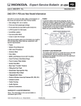
SP Diesel Performance Stage Ie/IIe/IIIe Series Modules – Jeep Liberty CRD 2.8L Common Rail
Installation Instructions
Thanks for your
purchase!
The staff at SP Diesel Performance thanks you for your recent purchase of the SP
Diesel Performance Module, the most tunable performance product on the market!
We are sure you will find all SP products to be an exceptional value for your dollar.
We have designed all SP products to be easy to install, while offering you better
results of similar or even higher dollar products.
Before you
begin
Before you begin installation you should make sure you have at least a basic
understanding of wiring. You don’t need to be an expert with our instructions but if
you aren’t comfortable, try and find a knowledgeable friend there to lend support, or
if all else fails we are available by email or phone. On a scale of technical difficulty,
installation of the SP Diesel Performance Module is a 2 on a scale of 10. Also as
with any electronic modification to your truck, remove the key from the ignition.
You should also consider disconnecting battery power from the truck, especially if
you are going to be crawling around on top of your engine. Pictures are supplied at
the end so you can print them out and keep them next to the text directions for easy
reference. All picture references will be noted in the instructions.
Key Features
The SP Diesel Module contains several new and exciting features you should be
aware of. More detail will be given later on how to use some of these features, and
some features may or not apply to your specific version.
•
•
•
•
•
•
•
•
Parts List
On the fly power level and display mode switching
Integrated Multi-Mode Display
Idle Pressure Compensation
Anti-Theft Mode
Valet/Weather Mode
Built in FE (Fuel Economy) Mode
PC Communication Capable (with SP Diesel Software and add-on
communications link)
Firmware upgradeable
See the below chart for a complete list of parts. Optional parts are noted as such in
the list.
•
•
•
•
(1) SP Diesel Performance Module
SP Diesel Performance Module Harness
Small Parts Kit for your installation (may not be necessary for all versions)
Add-On components such as boost controller card or PC Link ***(optional
and/or future planned features)
SI e/SII e/SIII e - Performance Modules with Integrated Display Features and Add-On
capability
Continued on next page
Installation Directions & User Manual – Jeep Liberty CRD Common Rail Turbo Diesel
Please read entire document before beginning installation and use
SP Diesel Performance. All Rights Reserved. Copyright 2005.
Page 1
SP Diesel Performance Stage Ie/IIe/IIIe Series Modules – Jeep Liberty CRD 2.8L Common Rail
SP Diesel Performance. All Rights Reserved. Copyright 2005.
SP Diesel Performance Stage Ie/IIe/IIIe Series Modules – Jeep Liberty CRD 2.8L Common Rail
Tools & Harness Installation/Installation Instructions (continued)
Tools
Harness Installation & Module Power Up/Installation Instructions (continued)
See the below chart of tools recommended for installation.
Tool
Long-Nose Pliers
Phillips and Flat Screwdriver
Electrical Tape
Zip Ties
Drill /drill bits
Straight bent coat hanger or fish tape
Wire Stripping/Crimping Tool
Plug in your
harnesses
Engine Bay
Ground
Purpose
They come in handy!
Multiple Uses
Various purposes
To clean up wiring runs and organize under the dash or under
hood.
For drilling hole in plastic access ports to engine bay from
passenger cabin and for mounting module
For fishing the harness through the firewall of the engine bay.
Used to make any additional non-plug in connections for your
performance module.
Your Performance Module or Performance Module has been shipped with a harness
to match your vehicles configuration. You should not need to alter the harness nor
use excessive force to seat the connectors. If you experience difficulties, please
contact us. Chances are you are plugging into the wrong location, or your vehicle
does not match specifications for that model year. Connection points are listed below
for reference. Please note with your module, not all connections may be made. The
chart below shows your connection points. Reference photos in figures 1.1 through
2.1 for locations and recommended install-easing tips.
Stage
e
JeepSI
e
JeepSII
Page 2
Connection Point(s)
Fuel Pressure Only plus Ground***
Fuel Pressure & Boost plus Ground***
Ground your harness using the ground wire coming off of the SP Diesel Performance
Module Harness. A ring terminal is supplied for convenient mounting to a suitable
good ground. Avoid grounding to places where other devices are already grounded.
A good clean ground is helpful for proper operation of the Performance Module
Series Module. It is generally not desirable to ground directly to the battery. In the
Jeep there are several spots near where the harness passed through the firewall that
are suitable grounds.
Find a location
to tap through
the firewall
Now that you have connected your harnesses and found a location to mount your
Performance Module, use a flashlight to locate a suitable location to pass a wire
through the firewall.
Run your
Harness
through the
firewall
Once you have identified a clean place to pass your harness through the firewall, go
ahead and pass it through. This is where a coat hanger or fish tape may come in
handy. Be sure to not ‘bugger’ up the harness connector when passing from engine
to cabin. If you so desire, a piece of electrical tape over the front of the connector
can help ease it through the passage you have created.
Connect
Harness to
Module
Connect your 8-way harness plug to the 8-way connector on the module. At this
point in time, you should unscrew the two screws on the box, approximately 3 turns
each and gently slide the connector to its mate on the board. Then re-tighten
screws, creating a positive lock of the connector to the board. This is a secondary
safety to prevent unintentional separation of the harness to the module. Should you
need to ever remove the module, reverse these directions and uninstall the harness
connector from the module.
Position your
module so that
it can be seen
Position the module such that you can see the display and easily get to the
switchgear on the module. You are almost there! You are supplied with some Velcro
Strips to give you options on placement.
Turn your key
to the ON
position
DO NOT START
Turn your key to the on position. Make sure that all normal startup lights on the dash
illuminate and go out as normal. On the first Key-On event, your module should
Display “SP” then “PL” then “0”, indicating that the module is powered up properly
and running in Power Level 0. Any other result is considered undesirable and you
should recheck your install procedures. If you do not discover any issues, please
email or call SP Diesel Tech Support for support.
Continued on next page
Note: Not all Harness Models include a separate ground. Some models may or may
not be equipped with extra wires as well. If they are not used, secure them to as to
not short on anything.
Remove the
Lower Dash
Panel
Remove the Lower Dash Cover from under the steering column. This will allow you
to see where your wires are going to pass in thru the engine bay plus it will allow you
to route the harness out through the steering column to the modules mounting
location. The Jeep Dash cover simply pops loose and is hinged at the bottom.
Continued on next page
SP Diesel Performance. All Rights Reserved. Copyright 2005.
Page 3
SP Diesel Performance. All Rights Reserved. Copyright 2005.
Page 4
SP Diesel Performance Stage Ie/IIe/IIIe Series Modules – Jeep Liberty CRD 2.8L Common Rail
SP Diesel Performance Stage Ie/IIe/IIIe Series Modules – Jeep Liberty CRD 2.8L Common Rail
Installation Instructions w/testing and operational procedures
Installation Instructions w/testing and operational procedures
Testing and Operational Modes & Procedures
IMPORTANT – Testing procedures must be performed to ensure your module is connected correctly.
Engine damage may result from starting your truck with the module connected incorrectly.
Testing and Operational Modes & Procedures
Operational
Mode Flow
Chart
Power Level
Adjustment
(PL)
The default mode for the display when you start the truck is PL or power level. While
in PL mode, you can use the UP/DN buttons to tune the power level you wish.
Depending on the model of your module and make of vehicle you may have a widely
varying number of levels from which to choose. This setting will be saved in your
module unless changed. The default value when shipped is Power Level 0.
Fuel Pressure
Display (FP)
If equipped, this mode may be selected by clicking the Mode or “M” button till you
see “FP” displayed. The oil pressure displayed is the pressure of the fuel in the high
pressure oil rail and is expressed in x1000psi. Your module may also be equipped
with Idle Pressure Compensation as detailed in the next information block.
Idle Pressure
Compensation
This mode is selected by clicking the Mode or “M” button till you see “PS” displayed.
On the CRD, no adjustments can be made to the boost levels at this time.
Anti-Theft
Setup(AS)
This mode is selected by holding the Mode or “M” button down for approximately 2
seconds until you see “AS” displayed. Reference the chart on the following page to
make your selection for Anti-Theft. Press and release the Mode button to exit AntiTheft Setup mode. When anti-theft mode is selected, if your truck is started the SP
Module’s display will remain blank except for flashing dots. To deactivate Anti-Theft
mode simply hold down the Mode or “M” button for 1 second until the modules
display returns to usual. Your truck will start as normal with Anti-Theft mode engaged
but if the truck is driven more then a few mph the SP Module will render your truck
undriveable and making it near impossible for a would be thief to drive off with your
truck. If you happen to forget that anti-theft mode is engaged and you experience
anti-thefts de-fueling strategy simply deactivate the anti-theft mode by holding the
Mode button down for 1 second and continue driving normally.
Cold Weather
and Cold Start
PL
Power Level
UP
DN
“HO” High Output
Power Level 0 to 9
“FE” Fuel Economy
FP
Fuel Pressure Gauge (x1000PSI)
Some injector, tuners, modules, and various aftermarket devices may affect idle
quality. There are also other reasons why you may want to change your idle
pressure range. With this in mind, the SIIe and higher incorporate Idle Pressure
Compensation to help you restore idle quality to a desirable level. You may also find
this feature helpful in quieting a noisy engine or boosting the power curve at the drag
strip. A relative range of +/-9 can be dialed in by using the UP/DN button at any time
while in FP mode. The display will return to pressure readouts after setting your
compensation level. This setting will be saved in your module unless changed.
Boost Display
(PS)
Please see the below chart to help you better understand the flow of operating
modes and adjustments.
UP Idle Fuel Pressure
DN
PS
Boost Pressure (PSI)
AS
Anti-Theft Setup
(Hold Mode Button for 2 seconds)
0
1
2
Activates Once
Always Activates
Never Activates
(Default Value When
Shipped)
During cold startup you should run in a PL between 0 or 3. If you do choose to run in
other modes while the vehicle is warming up, do not ‘hot shoe’ the truck. Keep your
foot out of it while the vehicle gets to full operating temperature. Use common
sense.
Continued on next page
SP Diesel Performance. All Rights Reserved. Copyright 2005.
Page 5
SP Diesel Performance Stage Ie/IIe/IIIe Series Modules – Jeep Liberty CRD 2.8L Common Rail
SP Diesel Performance. All Rights Reserved. Copyright 2005.
Page 6
SP Diesel Performance Stage Ie/IIe/IIIe Series Modules – Jeep Liberty CRD 2.8L Common Rail
Important Messages
Important Messages
Operating Procedures
IMPORTANT – Operating procedures must be completely understood and applied correctly.
Engine damage may result from an incorrectly operated module.
Performance
Product
Stacking
Warnings
We at SP Diesel pride ourselves in the hours and months of testing that have taken
place before offering this product to the market. We have designed this module to
work to its full potential on a stock truck, and work in conjunction (i.e. stacked) with
other performance products on the market. With that said we have not and will not
test the module with every possible combination of performance products on the
market. Now to the warnings.
CAUTION: Customers Stacking this Module on Propane or High Performance Chips,
Nitrous etc. READ THIS: The SP Diesel module you have purchased has been
designed to increase timing, fueling, boost parameters on an otherwise stock truck to
safe levels. When used in conjunction with the previously mentioned products it is
possible to increase the timing to far, where detonation and engine damage may
result. Since we cannot control the other performance products on your vehicle these
we recommend not stacking this product with other performance enhancing
electronics. We will be happy to discuss your particular performance application and
give you suggestions on the proper usage of the SP Diesel Module.
Pay Attention
to your driving
Yes we must state these things, but please use common sense while adjusting your
module while underway. Failure to pay enough attention to this warning and your
driving can result in serious injury or death. Keep your eyes on the road and your
hands on the wheel please. Yes use the gauges and cool features, but not at the
expense of your driving concentration. Be Safe.
Remove before
servicing
SP Diesel recommends you remove the SP Diesel module and/or any other SP
Diesel product prior to visiting the dealer. This avoids confusion from the dealer who
may not be familiar with these products. These products can also interfere with the
normal troubleshooting procedures that are used in repair facilities.
Intellectual
Property &
DMCA (Digital
Millennium
Copyright Act)
Since the SP Diesel Performance Module is an embedded design where the
knowledge of the circuit board schematic alone won’t allow you to copy the end
product, it is important for any SP Diesel Performance Module owner to understand
that both the circuit board as well as the code in the computer chip are copyrighted
intellectual property, subject to all the same protections as any other computer
software. If you attempt to circumvent any security, encryption, or other protections
in place to reverse engineer our work, we will prosecute you to the fullest extent of
the law. We don’t want to sound mean to our customers, but these things must be
stated. Your installation of this product indicates acceptance of the terms in this
document. Users shall not attempt to reverse engineer, decompile/recompile any
physical or program components of this product. Think of it in simple terms. You
own the physical equipment but not the design, nor the code that makes the product
useful. It is granted under a license to you for the period of time you own the
product. The license transfers to a new owner only if they read and accept these
terms.
Contact
Information
You may contact SP Diesel in case of technical assistance, orders, or questions
through the following:
[email protected]
SP Diesel Hotline: 443-541-3331
Obey all Local
Traffic
Laws/Vehicle
Ratings
SP Diesel recommends you obey all traffic laws and do not exceed vehicle or vehicle
component ratings. This probably means no smokey burn-outs and 100MPH blasts
down the street. Save that for the track please. Failure to do so may not only result
in a ticket or worse, but engaging in ‘street racing’ and other types of activities can
result in serious injury or death. If you must do so, don’t say you haven’t been
warned by us. Our lawyers insisted.
Disclaimers
Like any other products SP Diesel cannot be held liable for incorrect installation.
Installation of performing enhancing products is solely at your own risk. Check your
local diesel emissions laws prior to installation. SP Diesel is held harmless of
liability.
Gauges are
HIGHLY
Recommended
Due to the variances in stock engine and transmission programming, the SP Diesel
Performance Module can have varying results on Exhaust Gas Temperatures
(EGTs). For that reason we recommend the use of a pyrometer on your truck. Avoid
spending more than 2-3 seconds at redline to avoid spiking EGTs. Performance
Modules can drive EGTs to near redline temps on some trucks.
Continued on next page
SP Diesel Performance. All Rights Reserved. Copyright 2005.
Page 7
SP Diesel Performance. All Rights Reserved. Copyright 2005.
Page 8
SP Diesel Performance Stage Ie/IIe/IIIe Series Modules – Jeep Liberty CRD 2.8L Common Rail
Installation Pictures
Jeep Fuel
Pressure
Sensor
Figures 1.1-1.2 (clockwise from top Left).
1.1 Jeep Engine Cover- Remove oil cap then cover then replace cap during install.
1.2 Jeep Fuel and/or Boost Connectors. Drivers-side back of engine near fuel filter.
1.1
1.2
Jeep
Grounding
Point
Figure 2.1
Grounding Location for Jeep CRD is located on the drivers fenderwell near battery.
If this is crowded with accessories please find another suitable clean ground. Please
note some harnesses may have an integral ground and therefore this section can be
skipped. The battery is NOT an ideal location for grounding.
SP Diesel Performance. All Rights Reserved. Copyright 2005.
Page 9