1
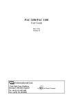
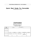
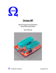
CEENBoT 324 User Manual Version 1.00 Copyright © CEENBoT Inc. 2010 Disclaimers The following documents are believed to be accurate, but carry no warranty, either expressed or implied. CEENBoT reserves the right to make changes without further notice to improve reliability and performance. The user assumes the risk to equipment and person(s) that are involved. Component Checklist Standard Product Checklist □ CEENBoT 324 Robot, complete or kit form with parts □ User Guide □ CEENBoT Controller Operation Guide Optional Product Checklist The following items may also be included with your CEENBoT: □ 7.2 V battery □ AC charger □ CEENBoT remote control, either wired or wireless □ Kit product assembly instructions (if purchased in kit form) Charging the battery Make sure the robot power is OFF before charging. The battery pack is not charged prior to shipment and must be charged fully charged before the first use. Depending on the charger and battery, this may take up to 8 hours. An audible tone indicates your battery is fully charged. After your first charge, future charges may require less time to charge the battery. Use only CEENBoT chargers and batteries with your CEENBoT. Plug the charger into a standard indoor electrical outlet. Verify the battery is connected to the robot. Make sure the robot is OFF and insert the polarized charger plug into the charger plug located on the side of the controller board. During charging with the power switch off, the LCD display will light, but nothing will be displayed. If the robot is powered on, the LCD will display the charging status. The charging time of the robot will be dependent on the charger and battery that are used. When the switch is in the ON position, the LCD display indicates the unit is CHARGING and will display CHARGED when the unit is fully charged A fully charged battery will last approximately 2 hours depending on operational mode and usage. Battery Installation The battery mounts to the bottom side of the robot frame. When installing the battery, make sure the wires do not interfere with wheel operation or drag on the ground. The battery cable can be tucked between the battery and chassis to keep it from dragging. Controller Operation Your CEENBoT can be operated using the optional Playstation-type wired or wireless controller. This controller is used to operate your robot in Tank mode and to change robot parameters. When in Tank mode, you can directly control the direction and speed of your CEENBoT. If you have a wireless unit, the controller and receiver have been synchronized and tested prior to shipment. AA batteries (included in the kit) may need to be installed in the back of your controller. The controller power switch is also located on the back of the unit. The power switch needs to be in the on position to operate. After several minutes of inactivity, your wireless controller may go into sleep mode to preserve the batteries. Press the refresh button (may be labeled analog on some remotes) to enable the remote. The red light on the remote indicates power has been restored to the controller. The wired controller connects directly to the circuit board and does not require batteries. When using a wired controller, the CEENBoT may come up in Bump Bot mode when the robot is powered on. If this happens, press the X button (right side bottom button) to switch your robot to Tank mode for direct control. R2 Increase Speed L2 Decrease Speed L1 - LCD Reverse R1 - LCD Forward Brake Control □ Wireless Synchronize Control Left Motor Control ↕ Bump Bot /Tank mode toggle X Right Motor Control ↕ Refresh Control R2 – increase speed (max 195 in analog mode) L2 – decrease speed (min 15 in analog mode) L1/R1 – toggle LCD screen Brake Control – When operating on a slope, enabling this will lock the wheels to prevent slippage. Refresh (analog on some controllers) – Press the refresh button to wake the remote from sleep mode. The red light on the remote indicates power has been restored to the controller. Left and Right Motor Control – The joysticks operate each motor independently forward and reverse. LCD Display When the switch of the robot is in the ON position, the LCD briefly displays the manufacturing and firmware version loaded before displaying the Battery Monitor screen. From here, you may toggle between screens using the left and right buttons under the LCD (S3 and S5) or using the L1 and R1 buttons on the controller. There are several display screens available on your CEENBoT to provide feedback to you for operation and education. Battery Monitor Screen On this screen, battery voltage, current, operation mode, and power usage are displayed. These can be useful when performing tests and experiments with your CEENBoT. Voltage ( Volts) Current (Amps) Mode (Run, Charging, Fully Charged) Power Usage (mAh) Control Screen When the robot is in Tank mode, the LCD displays the following information to assist you in controlling the CEENBoT. Left stick controls the left motor Right stick controls the right motor When the robot is in Bump Bot mode, the LCD displays “Bot will go forward until it detects something in its path, then it will turn”. Control Mode Screen This top line of the screen displays the current control status, Bump Bot or Tank mode. While in Bump Bot mode, the robot is autonomous and will operate until the bump sensor detects an obstruction. If you are operating in Tank mode, you are able to control the direction and speed though the controller. X on controller switches from Tank to Remote mode. Note: The center switch S4 under the LCD also will toggle the mode of operation from Tank to Remote. When in Tank mode, the left stick controls the left motor and the right joystick controls the right motor. When in Bump Bot mode, the current operation (forward/reverse/turn left/turn right) is displayed L1 on the controller toggles back one screen R1 on the controller toggles forward one screen PSX Ctrlr Read Data Screen The first two lines show the binary output from the controller. When the controller is operational, the values will change when the remote control buttons are pressed and joysticks are moved. The last line displays Analog or Digital mode. Wheel Revolutions Screen The screen displays the number of left and right wheel rotations in decimal and binary numbers since powering the robot. To clear the values, turn the robot off or press the reset button (S1). Left wheel L: decimal number (ex. 24) = binary number (ex. 0000011000) Right wheel R: decimal number (ex. 27) = binary number (ex. 0000011011) Speed Settings Screen The screen displays the current analog and digital speed settings of the robot. When in Tank mode, analog speed is used. If the robot is in Bump Bot mode, digital speed is used. To change the robot speed, use the controller R2 button to increase speed and the L2 button to decrease speed. In analog (Tank) mode, the minimum speed is 15 and the maximum speed setting is 195. In digital (Bump Bot) mode, the minimum speed is 15 and the maximum speed setting is 145. Firmware Level Screen This screen displays the current firmware version of ATmega and ATtiny on your robot. Printed Circuit Board On your CEENBoT printed circuit board, there are a number of switches, indicator lights, and displays that will assist you in the operation of the robot. They are outlined in the diagram below. The green indicator light on the bottom of the board indicates power and data transfer is taking place. The LED will flicker during data transfer. Charging Plug Fwd ON/OFF Wireless Receiver LCD Rev On = Tank mode Remote/Tank mode LCD Fwd On = Brake mode Trouble Shooting and Support Problem – Robot does not move Make sure the robot on/off switch is in the ON position and the green LCD is on. Check that the battery is installed in the robot. Make certain the battery is fully charged and powering the robot. Check metal contact tabs for dirty connections. Problem – LCD screen is blank Make sure the CEENBoT ON/OFF switch is in the on position. Move the power switch to the OFF position for 5 seconds and then move back to the ON position. Problem – Robot does not charge Check the charger and make sure both ends are firmly seated. When the CEENBoT is charging and the switch is in the ON position, the LCD will display CHARGING and also display the amount of time it has charged. After 15 minutes of charging, an audible beep will occur. After a full charge has been completed, a longer beep will occur and the LCD screen will indicate the charging is complete. If the robot battery does not hold its charge, contact your supplier to replace the battery. Use only CEENBoT batteries in your robot. Problem – Robot does not respond to controller Make sure the controller ON/OFF switch is in the ON position. The light on the controller and wireless receiver will be solid red when communicating with the robot. A blinking red light on either one indicates the devices are not communicating. If the wireless receiver on your robot is blinking, check the light on the hand held controller for power. If the controller is in sleep mode to conserve batteries, press the refresh button in the center of the remote or cycle power to the controller. See the controller diagram for the refresh button location. Check the + and – markings on the controller battery to match the + and – markings on the controller. Make sure there are fresh alkaline batteries in the controller. Make sure the wireless receiver is connected to the robot controller board. The red light on the radio receiver indicates the unit has power. If both the controller and receiver have blinking red lights, they are not communicating in a wireless mode and need to be synchronized. Press the “CONNECT” button on the robot receiver and the Wireless Connect button (See controller diagram for location) on the controller to synchronize communications. A solid red light on both indicates they are communicating. Make sure you are within the 50 foot range of the wireless remote control. Problem – Robot moves by itself When the remote is not present or communicating, the default mode is Bump Bot. This is normal behavior. Make sure the wireless remote controller ON/OFF switch is in the ON position. The red light on the controller indicates power. Make sure the remote controller and the remote receiver are communicating. The controller and receiver will have a solid red light when they are connected. Make sure there are fresh alkaline batteries in the controller. If the remote sensors are not present and the robot is in Bump mode, it will operate as if it constantly senses an obstruction.