1
TG1811_1812_1813AL(e-e).book Page 1 Friday, May 12, 2006 2:25 PM
Operating Instructions
Digital Cordless Phone
Model No.
KX-TG1811
Charge the batteries for about
7 hours before initial use.
KX-TG1811AL
KX-TG1812AL
KX-TG1813AL
Table of Contents
Introduction ............................................................ 2
Preparation ............................................................. 4
Making/Answering Calls ...................................... 12
Phonebook............................................................ 13
Useful Telephone Settings .................................. 14
Caller ID Service ................................................... 17
Multi-unit Operation ............................................. 19
Useful Information................................................ 20
You must subscribe to Caller ID service to use this
feature.
Caller ID
Please read these operating instructions before using the unit and save them for future
reference.
Only the included handset can be used with the base unit. No other handsets can be
registered or used.
TG1811_1812_1813AL(e-e).book Page 2 Friday, May 12, 2006 2:25 PM
Introduction
Introduction
Thank you for purchasing a new Panasonic digital cordless phone.
For your future reference
Attach or keep original receipt to assist with any repair under warranty.
Serial No. (found on the bottom of the unit)
Date of purchase
Name and address of dealer
Note:
L In the event of problems, you should contact your equipment supplier in the first instance.
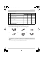
Your phone
KX-TG1811
KX-TG1812
KX-TG1813
Note:
L The handsets have been pre-registered for use with their base unit. If not registered, see
page 20.
2
TG1811_1812_1813AL(e-e).book Page 3 Friday, May 12, 2006 2:25 PM
Introduction
Included accessories
Quantity
No. Accessory items
KX-TG1811 KX-TG1812 KX-TG1813
1
AC adaptor for base unit
Part No. PQLV19AL
1
1
1
2
Telephone line cord*1
1
1
1
3
Rechargeable batteries AAA size
Part No. HHR-4EPT
2
4
6
4
Handset cover*2
1
2
3
5
Charger
Part No. PQLV30018
–
1
2
6
AC adaptor for charger*3
Part No. PQLV200AL
–
1
2
*1 The telephone line cord comes connected with the telephone plug.
*2 The handset cover comes attached to the handset.
*3 The AC adaptor for the charger comes connected with the charger.
1
2
3
4
5
6
Note:
L When replacing the batteries, use only 2 rechargeable AAA size nickel metal hydride (NiMH) batteries. We recommend using Panasonic rechargeable batteries (Model No. HHR4EPT).
L We cannot be responsible for any damage to the unit or degradation of performance which
may occur from using non-Panasonic rechargeable batteries.
3
TG1811_1812_1813AL(e-e).book Page 4 Friday, May 12, 2006 2:25 PM
Preparation
Preparation
Important information
General
L Use only the AC adaptor included with this
product, noted on page 3.
L Do not connect the AC adaptor to any AC
outlet other than a standard 220–240 V
AC outlet.
L This product is unable to make calls when:
− The portable handset battery(ies) need
recharging or have failed.
− There is a power failure.
− The key lock feature is turned on.
− The call bar feature is turned on (only
phone numbers stored in the unit as
emergency numbers can be called).
L Do not open the base unit or handset
other than to replace the battery(ies).
L This product should not be used near
emergency/intensive care medical
equipment and should not be used by
people with pacemakers.
L Care should be taken that objects do not
fall onto, and liquids are not spilled into,
the unit. Do not subject this product to
excessive smoke, dust, mechanical
vibration or shock.
Environment
L Do not use this product near water.
L This product should be kept away from
heat sources such as radiators, cookers,
etc. It should also not be placed in rooms
where the temperature is less than 5 °C or
greater than 40 °C.
L It is advised not to use the equipment at a
refuelling point. Users are reminded to
observe restrictions on the use of radio
equipment in fuel depots, chemical plants
or where blasting operations are in
progress.
L The AC adaptor is used as the main
disconnect device. Ensure that the AC
4
outlet is installed near the unit and is
easily accessible.
Warning:
L To prevent the risk of electrical shock, do
not expose this product to rain or any
other type of moisture.
L Unplug this unit from power outlets if it
emits smoke, an abnormal smell or makes
unusual noise. These conditions can
cause fire or electric shock. Confirm that
smoke has stopped and contact an
authorised service centre.
Battery caution
L We recommend using the battery(ies)
noted on page 3. Use only rechargeable
battery(ies).
L Do not mix old and new batteries.
L Do not dispose of the battery(ies) in a fire,
as they may explode. Check local waste
management codes for special disposal
instructions.
L Do not open or mutilate the battery(ies).
Released electrolyte from the battery(ies)
is corrosive and may cause burns or injury
to the eyes or skin. The electrolyte may be
toxic if swallowed.
L Exercise care when handling the
battery(ies). Do not allow conductive
materials such as rings, bracelets or keys
to touch the battery(ies), otherwise a short
circuit may cause the battery(ies) and/or
the conductive material to overheat and
cause burns.
L Charge the battery(ies) in accordance
with the information provided in these
operating instructions.
L Only use the included base unit (or
charger) to charge the battery(ies). Do not
tamper with the base unit (or charger).
Failure to follow these instructions may
cause the battery(ies) to swell or explode.
TG1811_1812_1813AL(e-e).book Page 5 Friday, May 12, 2006 2:25 PM
Preparation
Notice
L Please ensure that a separate telephone,
not dependent on local power, is available
for emergency use.
L This equipment will be inoperable when
mains power fails.
L When a failure occurs which results in the
internal parts becoming accessible,
disconnect the power supply cord
immediately and return this unit to an
authorised service centre.
L To minimise the possibility of lightning
damage, when you know that a
thunderstorm is coming, we recommend
that you:
− Unplug the telephone line cord from the
phone socket.
− Unplug the AC adaptor from the AC
power outlet.
L No “000” or other calls can be made from
this device during a mains power failure.
L The earpiece on the handset is
magnetised and may retain small metallic
objects.
L This equipment has been tested and
found to comply with AS/NZS 3548: 1995
limits for electromagnetic interference.
Any modifications to any part of the
system or to any peripherals may void the
EMC compliance of the system or the
peripherals.
5
TG1811_1812_1813AL(e-e).book Page 6 Friday, May 12, 2006 2:25 PM
Preparation
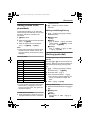
Instructions to customer
Installation
Attached to this telephone is an approval label. This label is evidence that it is a “Permitted
Attachment” which has been authorised to be connected to your telephone service.
Conditions relating to connection and operation of this Permitted Attachment are contained
in Telecommunications General By-Law 220 (5).
You are authorised to install this Permitted Attachment yourself by plugging it into the line
socket of any regular telephone. You may connect it in place of your existing telephone or to
any spare telephone socket installed in your premises.
To disconnect your existing telephone you must first remove its plug from the line socket. You
can then insert the plug of your Permitted Attachment into the socket and use your
equipment.
If the plug of your existing telephone cannot be readily removed, you will have to remove the
screw securing it. To do this proceed as follows:
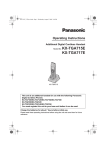
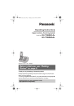
1 Loosen screw “A” sufficiently to remove the socket cover. (See Fig. 1.)
2 Remove screw “B” and withdraw the plug. (See Fig. 2.)
3 Replace screw “B”. (See Fig. 3.) Ensure that it screws completely into the socket recess.
(If the screw is too long, increase the hole depth or replace the screw with one 5 mm
shorter.)
4 Replace socket cover and tighten screw “A”. (See Fig. 4.)
SOCKET
PLUG
SCREW
“B”
SCREW “A”
Fig. 1
(
TELEPHONE CORD
Connect to the PLUG
as shown in Fig. 1.
Fig. 2
)
SCREW “A”
SCREW
“B”
Fig. 3
6
SOCKET
Fig. 4
TG1811_1812_1813AL(e-e).book Page 7 Friday, May 12, 2006 2:25 PM
Preparation
If you are satisfied with the operation of your telephone service after plugging in your
Permitted Attachment, your installation is completed.
You will be unable to connect this Permitted Attachment if your telephone service consists
only of a wall phone or an old style telephone which is not connected by means of a modern
plug and socket. In such cases a new socket will need to be installed.
Should the Permitted Attachment not operate when plugged into a socket, it is either faulty or
unsuitable for operation with your telephone service. It should be returned to the store where
purchased or to an Authorised Service Centre.
Service difficulties
If at any time a fault occurs on your telephone service carry out the following checks before
you call for service:
L Disconnect the Permitted Attachment and try using the service with the normal telephone.
L If the telephone service then operates satisfactorily, the fault is in your Permitted
Attachment. Leave the Permitted Attachment disconnected and report the fault to its
supplier or agent to arrange for repair.
L If when using the telephone the service is still faulty, report the fault to “Service Difficulties
and Faults” for attention.
You are required to keep this Permitted Attachment in good working order while it is
connected to your telephone service. Its construction or internal circuit must not be modified
in any way without permission.
Warning:
This cordless telephone system does not incorporate provision for secrecy of conversations.
Appropriately tuned radio equipment and other cordless telephone systems in close proximity
may be used by a third party to monitor and possibly interrupt conversations in progress when
this system is on radio operation.
7
TG1811_1812_1813AL(e-e).book Page 8 Friday, May 12, 2006 2:25 PM
Preparation
rotary (pulse dialling) services.
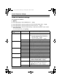
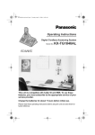
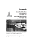
Connections
If you subscribe to an ADSL service
Base unit
Hooks
LINE
To telephone
network
L Please attach a noise filter (contact your
ADSL provider) to the telephone line
between the base unit and the telephone
line socket in the event of the following:
− Noise is heard during conversations.
− Caller ID features (page 17) do not
function properly.
(220–240 V,
50 Hz)
To socket
Use only the included AC adaptor
and telephone line cord.
Telephone line
cord
Charger (KX-TG1812 and KX-TG1813
only)
Noise filter
(For ADSL users)
Hooks
Location
(220–240 V,
50 Hz)
Use only the included AC adaptor.
Note:
L Never install telephone wiring during a
lightning storm.
L Do not connect the AC adaptor to a
ceiling-mounted AC outlet, as the weight
of the adaptor may cause it to become
disconnected.
L The unit will not work during a power
failure. We recommend connecting a
standard telephone to the same
telephone line or to the same telephone
socket using a telephone double adaptor.
L The unit is not designed to be used with
8
For maximum distance and noise-free
operation, place your base unit:
− Away from electrical appliances such as
TVs, radios, personal computers or other
phones.
− In a convenient, high and central location.
TG1811_1812_1813AL(e-e).book Page 9 Friday, May 12, 2006 2:25 PM
Preparation
Battery installation
Battery charge
Important:
L Wipe the battery ends (S, T) with a dry
cloth.
L Install the batteries without touching the
battery ends (S, T) or the unit contacts.
Place the handset on the base unit or
charger for about 7 hours before initial
use.
Insert the batteries negative (T) terminal
first. Close the handset cover.
Battery strength
Battery icon
054
Turning the power on/off
Power on
Press {ih} for about 1 second.
Power off
Press {ih} for about 2 seconds.
Fully charged.
5
High
6
Medium
7
Low
074
Note:
L Use only the included rechargeable
batteries (page 3, 4).
Battery strength
Needs to be charged.
Panasonic Ni-MH battery performance
Operation
Operating time
In continuous use
Approx. 10
hours max.
In continuous standby
mode
Approx. 120
hours max.
Note:
L It is normal for batteries not to reach full
capacity at the initial charge. Maximum
battery performance is reached after a few
complete cycles of charge/discharge
(use).
L Actual battery performance depends on a
combination of how often the handset is in
use and how often it is not in use
(standby).
L Even after the handset is fully charged,
the handset can be left on the base unit or
charger without any ill effect on the
batteries.
L The battery strength may not be displayed
correctly after you replace the batteries. In
this case, place the handset on the base
unit or charger and charge for at least 7
hours.
9
TG1811_1812_1813AL(e-e).book Page 10 Friday, May 12, 2006 2:25 PM
Preparation
Charger (KX-TG1812 and KX-TG1813
only)
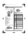
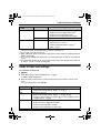
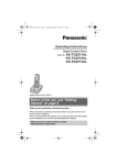
Controls
A
Handset
A
B
C
D
E
F
G
H
I
A
B
C
D
E
F
G
H
I
J
K
L
M
N
A Charge contacts
C
1
4
7
2
N
J
K
L
Displays
Icons
3
5
6
8
9
0
R
INT
w
M
H
0w4
Receiver
Display
{k} (Phonebook)
{C} (Talk)
Navigator ({e}/{v}/{>}/{<})
{R} (Redial/Pause)
{R} (Recall)
Charge contacts
Microphone
{j/OK} (Menu/OK)
{ih} (Off/Power)
{C} (Clear)
{INT} (Intercom)
Ringer
Within range of base unit
Out of range, no registration
or no power on base unit
x
Paging, intercom mode or
accessing base unit
k
Making or answering a call
C
Phonebook mode
l
Setting mode
5
Battery strength
Call bar is on (page 14).
Direct call is on (page 14).
Key lock is on (page 12).
Ringer volume is off (page
14).
Displayed when you press
{#}.
Base unit
A
B
LINE
A Charge contacts
B {x} (Page)
10
Meaning
If “BS NO” is selected for
standby mode display (page
14) and the current base unit
number is 1, “-1-” is
displayed.
TG1811_1812_1813AL(e-e).book Page 11 Friday, May 12, 2006 2:25 PM
Preparation
Icons
Meaning
If “HS NO” is selected for
standby mode display (page
14) and the current handset
number is 2, “[2]” is
displayed.
desired language, then press {>}. Press
{ih}.
Date and time
1 {j/OK}
2 Press {e} or {v} to select “SETTING
BS”. i {>} i {*}
4 new calls
When new calls have been received, the
display will show the number of new calls.
Symbols used in these
operating instructions
Symbol
Meaning
{j/OK}
Press {j/OK}.
i
Proceed to the next
operation.
“”
Select the words in quotations
shown on the display (e.g.,
“SETTING HS”) by pressing
{e} or {v}.
3 Enter the current hour and minute (24hour time entry).
L If you make a mistake, press {C}.
Digits will be cleared from the right.
4 {>} 2 times i {*} 2 times
5 Enter the current day, month, and year.
L If you make a mistake, press {C}.
Digits will be cleared from the right.
6 {>} i {ih}
Display language
1 {j/OK}
2 Press {e} or {v} to select “SETTING
HS”. i {>}
3 Press {e} or {v} to select “DISPLAY
OPT”. i {>}
4 Press {e} or {v} to select “LANGUAGE”.
i {>}
5 Press {e} or {v} to select the desired
language. i {>} i {ih}
Note:
L If you select a language you cannot read,
press {ih}, {j/OK}, press {v}, press
{>}, press {v} 3 times, press {>}, press
{v} 2 times, press {>}, select the
11
TG1811_1812_1813AL(e-e).book Page 12 Friday, May 12, 2006 2:25 PM
Making/Answering Calls
Making/Answering Calls
Making calls
1 Dial the phone number. i {C}
2 When finished talking, press {ih} or
place the handset on the base unit or
charger.
Answering calls
1 Press {C} to answer the call.
L You can also answer a call by pressing
any dial key from {0} to {9}, {*}, {#},
or {INT}. (Any key answer feature)
2 When finished talking, press {ih} or
place the handset on the base unit or
charger.
Handset locator
1 Press {x} on the base unit.
2 To stop paging, press {x} on the base
unit or press {C} on the handset.
To adjust the receiver volume
Press {e} or {v} while on a call.
Pause button (for PBX/long
distance service users)
A pause is sometimes required when
making calls using a PBX or long distance
service. Pressing {R} 1 time creates 1
pause. Press {R} repeatedly to create
longer pauses.
Redial functions (Redialling/
Storing/Editing before calling/
Erasing)
1 {R} i Press {e} or {v} to select the
desired number.
2 ■ Redialling:
12
{C}
■ Storing:
{>} i “SAVE TEL NO” i {>} i
{j/OK} i Enter the name (9
characters max.; page 13). i
{j/OK}
■ Editing before calling:
{>} i “EDIT CALL NO” i {>}
i Edit the number. i {C}
■ Erasing:
{>} i “CLEAR”/“ALL CLEAR” i
{>} i “YES” i {>} i {ih}
Key lock
The handset can be locked so that no calls
or settings can be made. Incoming calls can
be answered, but all other functions are
disabled while key lock is on.
To turn key lock on, press {j/OK} for about
2 seconds.
To turn key lock off, press {j/OK} for about
2 seconds.
R button (to use the recall
feature)
{R} is used to access optional telephone
services. Contact your service provider/
telephone company for details.
Note:
L If your unit is connected to a PBX (private
branch exchange), pressing {R} can allow
you to access certain features of your host
PBX such as transferring an extension
call. Consult your PBX dealer for details.
L You can change the recall time (page 15).
L You can access your service provider/
telephone company call waiting service by
having the recall time set at 100 msec.
(default setting, see page 15), and then
follow your service provider/telephone
company call waiting instructions to
operate this service.
TG1811_1812_1813AL(e-e).book Page 13 Friday, May 12, 2006 2:25 PM
Phonebook
number/character.
Phonebook
Adding entries to the
phonebook
2 {C} i Enter the correct number/
character.
The phonebook allows you to make calls
without having to dial manually. You can add
50 names and phone numbers to the
phonebook.
1 {j/OK} 2 times
2 Enter the party’s phone number (24 digits
max.). i {j/OK}
3 Enter the party’s name (9 characters
max.). i {j/OK} i {ih}
Note:
L When caller information is received and it
matches a phone number stored in the
unit’s phonebook, the stored name will be
displayed.
Character table
Making calls/Editing/Erasing
1 {k} i Press {e} or {v} to display
the desired entry.
2 ■ Making calls:
{C}
■ Editing:
{>} i “EDIT” i {>} i Edit the
phone number. i {j/OK} i Edit
the name. i {j/OK}
■ Erasing:
{>} i “CLEAR” i {>} i “YES”
i {>} i {ih}
Hot key (quick dial)
Assigning an entry in the phonebook to a
hot key
Keys
Characters
{1}
#
{2}
A
{3}
D
{4}
G
H
{5}
J
K
{6}
M N
O
6
{7}
P
Q
R
S
{8}
T
U
V
8
{9}
W X
Y
Z
{0}
(Space)
]
*
B
C
2
E
F
3
Dial keys {1} to {9} can each be used as a
“hot key”, allowing you to dial a number from
the phonebook by simply pressing a dial
key.
I
4
1 {k} i Press {e} or {v} to display
L
5
[
,
–
/
1
the desired entry. i {j/OK}
7
9
0
Note:
L To enter another character located on the
same dial key, press {>} to move the
cursor to the next space, then press the
appropriate dial key.
To edit/correct a mistake
1 Press {<} or {>} to move the cursor to
the right of where you want to correct the
2 “HOT KEY REG” i {>}
3 Select the desired dial key. i {>}
L If the dial key is already assigned as a
hot key, the displayed number will
flash.
4 “YES” i {>} i {ih}
Making calls/Erasing
1 Press and hold the desired hot key ({1} to
{9}).
2 ■ Making calls:
{C}
■ Erasing:
{>} 2 times i “YES” i {>} i
{ih}
13
TG1811_1812_1813AL(e-e).book Page 14 Friday, May 12, 2006 2:25 PM
Useful Telephone Settings
Useful Telephone Settings
Guide to handset settings
To customise the handset:
1
2
3
4
5
{j/OK}
Press {e} or {v} to select “SETTING HS”. i {>}
Press {e} or {v} to select the desired item in the handset settings menu. i {>}
Press {e} or {v} to select the desired item in the sub-menu. i {>}
Press {e} or {v} to select the desired setting, or follow the instructions in the “Feature”
column of the chart.
L To exit the operation, press {ih}.
Handset settings
menu
Sub-menu
Feature (default setting)
TIME ALARM
SET TIME
Set time alarm.
L Set the date and time beforehand (page 11).
− Enter the desired hour and minute (24hour time entry). i {>}
− Select the desired setting. i {>}
SET ALARM
Change alarm frequency (“OFF”).
RINGER OPT
RINGER VOL
Handset ringer volume (level 6)
EXT RINGER
Ringer type for external calls (“RING TYPE 1”)
INT RINGER
Ringer type for internal calls (“RING TYPE 1”)
PAGING
Ringer type for page (“RING TYPE 1”)
ALARM
Ringer type for alarm (“RING TYPE 1”)
KEY TONE
Keytones on/off (“ON”)
CALL WAITING
Call waiting tone on/off (“ON”)
TONE OPT
DISPLAY OPT
CALL OPT
14
RANGE ALARM
Range alarm on/off (“OFF”)
BATTERY LOW
Battery low alarm on/off (“ON”)
STANDBY MODE
Standby mode display (“CLOCK”)
TALK MODE
Talk mode display (“TALK TIME”)
LANGUAGE
Display language (“ENGLISH”): page 11
CALL BAR
Call bar on/off (“OFF”)*1
− Enter handset PIN (default: “0000”).*2
− Select the desired setting. i {>}
DIRECT NO
Store direct call number.*3
− Enter a phone number (24 digits max.).
− {j/OK} 2 times i “ON” i {>}
SET DIRECT
Direct call on/off (“OFF”)
TG1811_1812_1813AL(e-e).book Page 15 Friday, May 12, 2006 2:25 PM
Useful Telephone Settings
Handset settings
menu
Sub-menu
Feature (default setting)
OTHER OPT
HSPIN CHANGE
Change handset PIN (“0000”).*4
− Enter the current 4-digit handset PIN.*2
− Enter the new 4-digit handset PIN.
− Enter the new 4-digit handset PIN again.
AUTO TALK
Auto talk on/off (“OFF”)*5
RESET HS
—————
Reset handset to its default settings.
− Follow steps 1, 2, and 3.
− Enter handset PIN (default: “0000”).*2
− {v} i {>}
*1 Call bar feature prohibits making outside calls. When call bar is turned on, only emergency
calls can be made. To store emergency numbers, see page 16.
*2 If you forget your PIN, see page 21.
*3 Direct call feature allows you to dial a preset phone number simply by pressing {C}. No
dialling is necessary.
*4 If you change the PIN, please write down your new PIN as the unit will not reveal the PIN
to you.
*5 Auto talk feature allows you to answer calls simply by lifting the handset off the base unit
or charger. You do not need to press {C}.
Guide to base unit settings
To customise the base unit:
1 {j/OK}
2 Press {e} or {v} to select “SETTING BS”. i {>}
L “INPUT CODE” is displayed.
3 Enter the desired code number. Follow the instructions in the “Feature” column of the
chart.
L To exit the operation, press {ih}.
Code No.
Feature (Default setting)
{0}
Reset base unit to its default settings.*1
− Enter base unit PIN (default: “0000”).*2 i {>}
{3}
Recall time (100 ms)*3
− Enter base unit PIN (default: “0000”).*2 i {2} i {1}
− Select the desired setting by pressing {1} for 700 ms, {2} for 100 ms
or {3} for 90 ms. i {>}
{5}
Change base unit PIN (“0000”).*4
− Enter the current 4-digit base unit PIN.*2
− Enter the new 4-digit base unit PIN.
− Enter the new 4-digit base unit PIN again.
15
TG1811_1812_1813AL(e-e).book Page 16 Friday, May 12, 2006 2:25 PM
Useful Telephone Settings
Code No.
Feature (Default setting)
{6}
Call restriction*5
■ Setting call restriction
− Enter base unit PIN (default: “0000”).*2 i Press the desired
handset numbers. i {>}
− Enter the phone number to be restricted (8 digits max.).
L To select a different memory location, press {>} and enter a
number.
− {>}
■ Turning on/off call restriction
− Enter base unit PIN (default: “0000”).*2
L Handset number will be displayed. A flashing number indicates
call restriction is on; a non-flashing number indicates call
restriction is off.
− Press the desired handset numbers to turn on/off. i {>} 2 times
Emergency number (“000”, “106”)*6
− Enter base unit PIN (default: “0000”).*2 i {*}
■ Storing:
− Enter the emergency number (8 digits max.).
L To select a different memory location, press {>} and enter a
number.
− {>}
■ Editing:
Press {>} to display the desired number. i {C} i Enter the
new emergency number. i {>}
{*}
Date and time: page 11
*1 Only the emergency number setting will not be reset.
*2 If you forget your PIN, see page 21.
*3 Change the recall time if necessary to suit your PBX or service provider/telephone
company. For further information, consult your nearest Panasonic service centre.
*4 If you change the PIN, please write down your new PIN as the unit will not reveal the PIN
to you.
*5 Call restriction feature restricts the handset from dialling certain phone numbers. You can
assign up to 10 phone numbers (memory locations 0–9) to be restricted.
*6 Emergency number feature determines which phone numbers may be dialled while the
call bar feature is turned on. A total of 4 emergency numbers (memory locations 1–4) can
be stored.
16
TG1811_1812_1813AL(e-e).book Page 17 Friday, May 12, 2006 2:25 PM
Caller ID Service
Important:
L This unit is Caller ID compatible. To use
Caller ID features (such as displaying
caller phone numbers), you must
subscribe to Caller ID service. Consult
your service provider/telephone company
for details.
You can answer the 2nd call, keeping the
1st call on hold. Follow your service
provider/telephone company instructions
using {R}.
L If the phone number is stored in the
phonebook with its name, the caller’s
name will also be displayed.
L Please contact your service provider/
telephone company for details and
availability in your area.
Caller ID features
For Caller ID type II users
Caller ID Service
Using Caller ID service
Display indications
L When new calls have been received, the
display will show the number of new calls.
Example: 4 new calls have been
received.
L Phone numbers of the last 50 different
callers will be logged in the caller list.
Example:
*1
When you receive a 2nd call during a
conversation, you will hear a signal tone
following the call waiting tone and the
conversation will be interrupted or
muted for a short period of time. This is
not the fault of the product as these events
are normal.
L The tones are generated by the service
provider/telephone company.
Storing/Editing/Erasing
1 Press {e} or {v} to display the desired
entry. i {>}
2 ■ Storing:
*1 Shown when this call has already been
viewed or answered. Press {C} to call
back.
L “OUT OF AREA”: When the caller dialled
from an area which does not provide
Caller ID service.
L “PRIVATE”: When the caller requested
not to send caller information.
Call waiting and Caller ID
compatible
“SAVE TEL NO” i {>} i {j/OK}
i Enter the party’s name (9
characters max.; page 13). i
{j/OK} i {ih}
■ Editing:
“EDIT CALL NO” i {>} i Press
{<} or {>} to move the cursor to the
right of where you want to edit the
number. i Edit the phone number.
i {C}
■ Erasing:
“CLEAR”/“ALL CLEAR” i {>} i
“YES” i {>} i {ih}
If you subscribe to Caller ID service, your
handset displays the 2nd caller’s
information while talking. After you hear a
call-waiting tone, the caller’s phone number
will be displayed.
17
TG1811_1812_1813AL(e-e).book Page 18 Friday, May 12, 2006 2:25 PM
Caller ID Service
Voice mail service
Voice mail is an automatic answering
service offered by your service provider/
telephone company. If you subscribe to this
service, your service provider/telephone
company’s voice mail system will answer
calls for you when you are unavailable to
answer the phone or when your line is busy.
Messages are recorded by your service
provider/telephone company, not your
telephone. Please consult your service
provider/telephone company for details of
this service.
18
TG1811_1812_1813AL(e-e).book Page 19 Friday, May 12, 2006 2:25 PM
Multi-unit Operation
Multi-unit Operation
Intercom between
handsets (KX-TG1812 and
KX-TG1813 only)
Intercom calls can be made between
handsets in the same radio cell.
Example: When handset 1 calls handset 2
1 Handset 1:
{INT} i Press {2} (desired handset
number).
2 Handset 2:
Press {C} to answer.
Transferring a call without speaking to
the other handset user
1 During an outside call, press {INT}. i
Press the desired handset number.
L k flashes to indicate the outside call is
on hold.
2 {ih}
L The outside call rings at the other
handset.
Note:
L If the other handset user does not answer
the call within 30 seconds, the call will ring
at your handset again.
3 When finished talking, press {ih}.
Transferring calls/
conference calls, between
handsets (KX-TG1812 and
KX-TG1813 only)
Outside calls can be transferred between 2
people in the same radio cell. 2 people in the
same radio cell can have a conference call
with an outside party.
Example: When handset 1 transfers a call
to handset 2
1 Handset 1:
During an outside call, press {INT} i
Press {2} (desired handset number).
L The outside call will be put on hold.
L If there is no answer, press {INT} to
return to the outside call.
2 Handset 2:
Press {C} to answer the page.
L Handset 2 can talk with handset 1.
3 Handset 1:
To complete the call transfer, press
{ih}.
To establish a conference call, press {3}.
19
TG1811_1812_1813AL(e-e).book Page 20 Friday, May 12, 2006 2:25 PM
Useful Information
Useful Information
Troubleshooting
If you still have difficulties after following the instructions in this section, disconnect the AC
adaptor and turn off the handset, then reconnect the AC adaptor and turn on the handset.
Problem
Cause & solution
w is flashing.
L The handset is too far from the base unit. Move closer.
L The AC adaptor is not connected. Check the connections.
L You are using the handset or base unit in an area with high
electrical interference. Place the handset and base unit
away from interference sources, such as antennas and
mobile phones.
L The handset registration is cancelled. Register the handset
to the base unit (page 21).
I cannot make or
receive calls.
L The AC adaptor or telephone line cord is not connected.
Check the connections.
L The call bar feature is turned on. Turn it off (page 14).
L You dialled a call restricted number (page 16).
L The key lock feature is turned on. Turn it off (page 12).
L The unit is not designed to be used with rotary (pulse
dialling) services.
The unit does not ring.
L The ringer volume is turned off. Adjust the ringer volume
(page 14).
The handset display is
blank.
L The handset is not turned on. Turn the power on (page 9).
The handset will not turn
on.
L Make sure that the batteries are installed correctly (page 9).
L Fully charge the batteries (page 9).
A busy tone is heard
when {C} is pressed.
L The handset is too far from the base unit. Move closer and
try again.
Static, sound cuts in/
out, fades. Interference
from other electrical
units.
L Place the handset and the base unit away from other
electrical appliances.
L Move closer to the base unit.
L Your unit is connected to a telephone line with ADSL
service. We recommend connecting a filter (contact your
ADSL service provider) to the telephone line between the
base unit and the telephone line socket.
Noise is heard during a
call.
L You are using the handset or base unit in an area with high
electrical interference. Place the handset and base unit
away from interference sources, such as antennas and
mobile phones.
20
TG1811_1812_1813AL(e-e).book Page 21 Friday, May 12, 2006 2:25 PM
Useful Information
Problem
Cause & solution
Pressing {R} does not
display/dial the last
number dialled.
L The redialled number was more than 24 digits long. Redial
the number manually.
I fully charged the
batteries, but 074
still flashes.
L Clean the charge contacts and charge again (page 9).
L It is time to replace the batteries (page 9).
I fully charged the
batteries, but the
operating time seems to
be short.
L Wipe the battery ends (S, T) and the unit contacts with a
dry cloth. Charge the batteries for 7 hours before reuse.
Caller information is not
displayed.
L You must subscribe to Caller ID service.
L Your unit is connected to a telephone line with ADSL
service. We recommend connecting a filter (contact your
ADSL service provider) to the telephone line between the
base unit and the telephone line socket.
L Caller has withheld information.
I cannot remember the
PIN.
L Change the PIN (page 21).
Registering a handset
1 {j/OK} i “SETTING HS” i {>}
2 “REGISTRATION” i {>}
3 “REGISTER HS” i {>}
4 Press and hold {x} on the base unit for
about 5 seconds.
L If all registered handsets start ringing,
press {x} to stop, then start again
from step 1.
L The rest of the procedure must be
completed within 1 minute.
5 Press {e} or {v} to select a base unit
number. i {>}
6 Wait until “BS PIN” is displayed. i
Enter base unit PIN (default: “0000”).
i {>}
L If you forget your PIN, see page 21.
L A confirmation tone will sound, and
w will stop flashing.
L If w is still flashing, start again from
step 1.
Changing the PIN
Handset PIN:
1 {j/OK} i “SETTING HS” i {>}
2 “OTHER OPT” i {>}
3 “HSPIN CHANGE” i {>} i
{*}{7}{0}{0}{0}
4 Enter the new 4-digit handset PIN.
5 Enter the new 4-digit handset PIN
again. i {ih}
Base unit PIN:
1
2
3
4
{j/OK} i “SETTING BS” i {>}
{5} i {*}{7}{0}{0}{0}
Enter the new 4-digit base unit PIN.
Enter the new 4-digit base unit PIN
again. i {ih}
21
TG1811_1812_1813AL(e-e).book Page 22 Friday, May 12, 2006 2:25 PM
Useful Information
Specifications
■ Number of channels: 120 Duplex
Channels
■ Frequency range: 1.88 GHz to 1.9 GHz
■ Duplex procedure: TDMA (Time
Division Multiple Access)
■ Channel spacing: 1,728 kHz
■ Bit rate: 1,152 kbit/s
■ Modulation: GFSK (Gaussian
Frequency Shift Keying)
■ RF transmission power: Approx.
250 mW
■ Power source: 220–240 V, 50 Hz
■ Power consumption:
Base unit:
Standby: Approx. 3.5 W
Maximum: Approx. 9.2 W
Charger*1:
Standby: Approx. 0.6 W
Maximum: Approx. 5.0 W
■ Operating conditions: 5 °C–40 °C,
20 %–80 % relative air humidity (dry)
■ Dimensions:
Base unit: Approx. 58 mm × 123 mm ×
115 mm
Handset: Approx. 143 mm × 48 mm ×
32 mm
Charger*1: Approx. 60 mm × 86 mm ×
84 mm
■ Mass (weight):
Base unit: Approx. 180 g
Handset: Approx. 120 g
Charger*1: Approx. 120 g
*1 KX-TG1812 and KX-TG1813 only
Note:
L Specifications are subject to change.
L The illustrations used in these operating
instructions may differ slightly from the
actual product.
22
TG1811_1812_1813AL(e-e).book Page 23 Friday, May 12, 2006 2:25 PM
Useful Information
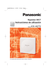
Wall Mount Template for base unit
Wall mounting
Note:
L Be sure to choose a location close enough
to connect the telephone line cord and AC
adaptor securely.
1 Connect the telephone line cord and AC
adaptor cord to the base unit.
2 Drive the screws (not included) into the
80 mm
wall. Make sure to use the wall mounting
template for correct positioning. Mount
the unit by inserting the screws into the
round openings at the rear of the base
unit, then sliding the unit down to secure
it.
Connect the AC adaptor to power outlet
(page 8) and the telephone line cord to
the telephone line socket.
Base unit
80 mm
Charger (KX-TG1812 and KX-TG1813
only)
28 mm
Screws
Wall Mount Template for charger
28 mm
Screws
23
TG1811_1812_1813AL(e-e).book Page 24 Friday, May 12, 2006 2:25 PM
Customer Support Centre Tel. No.: 132600 or website www.panasonic.com.au
N52
Sales Department:
Panasonic Australia Pty. Limited
Austlink Corporate Park
1 Garigal Road
Belrose
NSW 2085
AUSTRALIA
Panasonic Communications Zhuhai Co., Ltd.
3 Ping Xi 8 Lu, Nanping Keji Gongye Yuan, Zhuhai, Guangdong, China 519060
Copyright:
This material is copyrighted by Panasonic Communications Co., Ltd., and may be reproduced
for internal use only. All other reproduction, in whole or in part, is prohibited without the written
consent of Panasonic Communications Co., Ltd.
© 2006 Panasonic Communications Co., Ltd. All Rights Reserved.
PQQX15264ZA
DC0506DM0