1
A simulated system for teaching computer
architecture
Paolo Corsini and Luigi Rizzo
Dipartimento di Ingegneria dell'Informazione, Universita di Pisa
via Diotisalvi 2, 56126 Pisa
Phone +39-50-568533 { FAX +39-50-568522
email fp.corsini,[email protected]
Abstract
The evolution of computers has led to the current generation of powerful, RISC-based
workstations. These systems are often rich of interesting architectural features and
peripheral devices. Very often, they also run multitasking, multiuser operating systems
which make almost complete use of the available hardware.
This makes it very hard to use these systems for the lab classes of a computer
architecture course, to show how to deal with peripherals and mechanisms such as
interrupt and memory protection. In fact, working on these subjects almost unavoidably means breaking, thus loosing, a lot of the support provided by the operating
system, not to mention the possibility of wiping out data from the storage devices.
In order to overcome these diculties, and to be able to support the teaching of
computer architecture with signi cant experiments in a controlled environment, we
have developed a simulated computer system running under Unix. The simulated
system consists of CPU, memory and its peripherals, and has a complete interrupt
mechanism which permits the study of advanced techniques for peripheral management and other operating system's issues. The simulator runs on a variety of Unix
platforms, both with and without a windowing system. The paper describes the architecture of the system and shows some examples of its use.
1 Introduction
An important part in a course on computer architecture deals with the various mechanisms which are present in a computer for handling peripherals, such as I/O instructions,
interrupts, privilege levels. In order to support the teaching of these subjects, it is useful
to make experiments and show in practice the correct way of using these mechanisms.
This work has been developed as part of a joint didactical program between the \Dipartimento di
Ingegneria dell'Informazione dell'Universita di Pisa" and IBM Italia
1
The hardware platforms to be used for these experiments should be the workstations
with RISC processor and Unix operating system that are and will be increasingly available
in the nineties. However, the variety of di erent models, the general lack of documentation
on their architecture, the low visibility, from the user point of view, of base mechanisms
(I/O instructions, interrupt and protection) which are in use by the operating system,
make it hard to use these systems in lab classes, without having to interact too much with
the details of the operating system. This is undesirable, as a lab session is usually more
productive if the following conditions are satis ed:
the student should concentrate himself on the problem under study, rather than
being distracted by implementation details;
the experiment should be easy to monitor;
the experiment should be non trivial, whenever possible, in order to be more interesting. This means, for example, that we should not limit ourselves to turn on a
light or exchange a few character strings with a terminal.
To this purpose, we have developed a simulated environment that runs on common Unix
workstations, and allows the student to experiment on signi cant aspects of computer
architecture, up to the writing of a complete multitasking kernel, without incurring in all
the problems indicated above.
Our approach, i.e. using a simulated environment, has several advantages over the use
of bare hardware. We have already cited the problem that usually exist in getting detailed
documentation on the hardware structure of a modern workstation. Even if these details
are known, we must keep in mind that computers are generally made with very exible
components, whose capabilities are only partially exploited in a given experiment (not to
mention the fact that sometimes it is even necessary to use special care in order to get
around bugs or \undocumented features" of the hardware).
Even from the software point of view, the knowledge required to put hands on an existing operating system kernel is well beyond the one available to the average user, and the
intricacies which are present in a real system are not suited to didactical purposes. Our
system explicitly hides all the programming details that are not relevant to the experiment
being carried on, giving a simpli ed view of the machine and allowing the user to concentrate on the signi cant parts of the problem. Besides, an important advantage of using a
simulated system is the ease with which peripherals can be added/removed/modi ed to
make new experiments.
The ability to monitor the experiments plays an important role in lab sessions. Playing
with low level features of the hardware reduces our control over both the system and the
program, while the chance of software crashes grows considerably. With our system, all
2
the experiments actually occur in a simulated environment, so that it is much easier to
monitor their evolution, and the system is much more robust to programming errors.
An important aspect we want to emphasize is to show that all the architectural aspects of a system can be explored without recurring to the Assembler language, powerful
but too low level and very cryptic in modern RISC processor [3, 7]. Rather, the same
things can be done by using a high level language such as C, together with a very small
library of functions (just seven in our example) which encapsulate the instructions that
cannot be written directly in C and deal with I/O interfaces and interrupt and protection
mechanisms.
A nal consideration should be done about performance. Our simulator is programmed
in C; user programs are compiled using the system's compiler, and are run at full speed
by the system's processor. Thus, the penalty of simulation is only incurred when dealing
with I/O devices: other activities can fully exploit the speed of the system, making the
simulator useful even for building larger experiments.
The environment described in this paper is part of a series of didactical tools developed by the authors and used to support the teaching of digital circuits and computer
architecture. These include SYNCONET [2], a graphic program which shows the synthesis
of combinational circuits using Karnaugh maps and prime implicant charts; SSCSSC [1], a
tool for the simulation and synthesis of combinatorial and sequential synchronous circuits;
POPC, to supports the synthesis of microprogrammed systems; and EBx86, a shell which
eases the use of assembly language on MSDOS PCs.
The software described in this paper has been tested on several architectures and Unixlike operating systems, including AIX, Ultrix, FreeBSD, Linux. The user interface in the
graphic version of the program is based on the Tk/Tcl toolkit [8].
2 System Architecture
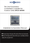
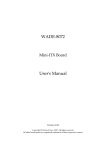
Students are presented a system with the structure shown in Figure 1. As can be seen
from the gure, the user's workstation is logically split in two parts: the host system and
the target system. The host system inherits all the features (hardware, software) of the
workstation; the target system is a nude computer fully available to the user. Host and
target are connected by means of a special (simulated) piece of hardware called host-target
interface.
The target is made of a processor with interrupt capabilities, a memory space and an
I/O space where a set of peripheral interfaces have been mounted; these include a timer,
some serial communication peripherals and a disk subsystem. The simulated hardware
can be con gured at run time to include a number of interfaces of each kind, and with
little programming e ort other interface types can be added to the simulator.
3
TARGET
CPU
MEM
HOST
TIMER
host/
target
interface
CROSS
DEVELOP.
ENVIRON.
SERIAL
...
SERIAL
CONSOLE
DISK
Figure 1: The architecture of the system as it is presented to the user.
Software development (editing, compiling and linking) occurs the host system. The
host is \magically" able to load the memory of the target system with the user program,
and start execution.
The functional aspects of all the modules constituting the target will be described in
detail in the following sections, with the exception of the the host-target interface, which is
presented to the students as a black box, and whose internals are thus not described here.
An important feature of the host-target interface is the ability to be used by the target in
a transparent way to communicate with the host console, provided that the user inserts
calls to standard library functions such as printf() and getchar() in its programs. The
host-target interface also makes it possible to monitor the status of the target system,
including the contents of the internal registers of the I/O interfaces.
2.1 Processor
The processor of the target is derived from the native processor of the workstation where
the simulator is run. All critical features of the native processor (interrupt and protections
mechanisms, and I/O instructions) are not inherited by the (simulated) processor, which
has its own interrupt and protection mechanisms, and two I/O instructions. Depending
on the programming language which has been chosen, the user can see the machine registers (e.g. when programming in assembler), or just have a high-level-language view of
the processor, without the need to know about the instruction set and the registers. In
particular, we emphasize the use of the C language [5] in order to be as independent as
possible from the actual processor.
In addition to the standard instructions and registers, the processor of the target is
enhanced with two privilege levels, an interrupt mechanism, and a couple of ags. The
4
Function
cli()
sti()
trap(interrupt type)
iret()
clp()
out(io addr, expr)
variable=in(io addr)
Description
disable interrupts
enable interrupts
invoke software interrupt
returns from interrupt
enter user state
out to I/O space
input from I/O space
Privileged
Yes
Yes
No
Yes
Yes
Yes
Yes
Table 1: The C interface of the extended instructions
current privilege level is determined by the state of a privilege ag. In privileged state, all
instructions can be executed; in user state, only a subset of the instructions (non privileged
instructions) can be executed. The processor can also accept asynchronous interrupts, if
the interrupt ag is set. The instructions that manage the interrupt and protection
mechanisms, and the two I/O instructions, are not directly accessible to the programmer,
but are encapsulated into library functions included in the development system. The C
interface of these functions is listed in Table 1, and their use will be illustrated in the rest
of this paper.
At system startup, the processor starts in privileged state and remains in this state
until the clear privilege flag instruction is executed. The clp() function encapsulates
the clear privilege flag instruction. There is no explicit way to raise the privilege ag
(and thus enter the privileged state): the only possibility is to execute the trap instruction,
encapsulated in the trap() function, which will enter privileged state and transfer control
to an appropriate handler.
2.1.1 Interrupts
The normal ow of execution can be interrupted by external events coming from peripheral
interfaces. We assume that the processor has a sucient number of interrupt lines, which
can be globally enabled or disabled depending on the status of an interrupt ag. Also,
we assume that each I/O interface which generates interrupts is labeled with an 8 bit
identi er (interrupt type), which is used to choose an appropriate handler to be executed.
The interrupt type is held in a register of the interface, which sends its content to the
processor when the interrupt request is accepted. The interrupt type is used by the
processor itself as an index in a table (interrupt table) containing the handlers' entry
points. The interrupt table is mapped in memory and can be accessed and modi ed in
privileged state only. Accesses to the interrupt table are unde ned in user mode.
5
Software interrupts of any type, and some hardware exceptions (generated internally
by the processor) are also possible; in these cases the execution proceeds as with external interrupt processing, i.e. the processor switches to privileged state before starting
execution of the pertinent handler. A typical hardware exception is generated when the
execution of a privileged instruction is attempted while the processor is in user state.
The sti() and the cli() functions presented in Table 1 encapsulate the privileged
instructions for setting/clearing the interrupt ag (thus enabling/disabling the processor to
accept interrupt requests). The trap() function encapsulates the instruction for software
interrupt.
2.2 Memory
Memory is seen as a single, linear space, with no management mechanisms such as paging
or segmentation, and almost no protection: the only exception is the interrupt table, which
is accessible only in privileged state1 Being inherited from the real memory system of the
workstation, the size and location of memory in the addressing space is not at a xed
address. This does not constitute a problem, however, because the compiler allows the
user to access memory with symbolic names. A special portion of the memory space is
dedicated to the interrupt table; it resides in a memory area which can be accessed only
in privileged state, and is disabled in user state. This is the only kind of protection which
exists in the memory subsystem.
2.3 Interfaces
Peripheral interfaces are mapped into a private addressing space (I/O space) and accessed
by invoking the in() and out() functions (that encapsulate the homonymous instructions). The in() function reads a byte from the speci ed I/O address, while the out()
function writes the speci ed byte expression to the speci ed I/O address.
Each interface consists in a set of registers, whose number and functions depend on the
particular interface. In our system, all interface are able to generate interrupts, and thus
have a TYPE register which identi es the actual handler to be executed upon interrupt.
Accessing the registers of the interface may causes the latter to react accordingly to its
speci cations.
Several interfaces can be con gured in the system, depending on the user's needs. In
the following, we will describe the interfaces which are supported by the current version
of the simulator.
Depending on the CPU and OS of the workstation where the simulator is run, certain memory areas
(such as code and constant data) can be write protected.
1
6
TIME_L
TYPE
TIME_H
STATUS
END_COUNT
CONTROL
START_COUNT
CICLIC
INT_ENABLE
Figure 2: Timer registers
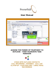
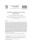
2.3.1 Timer
A timer is a fundamental device for a multiprogrammed system, in that it schedules
important events in the system such as task switchings and the like. In our system there
is a single timer, which can be programmed to count once or cyclically, and possibly to
generate an interrupt at the end of the count. Its registers are shown in Figure 2.
Programming the timer involves loading the 16-bit count length into the TIME H and
TIME L registers, and selecting the operating mode and enabling the timer via the CONTROL
register. When the timer is enabled, an internal counter is decremented at 100Hz frequency; at the end of each count the END COUNT bit in the STATUS register is set, and an
interrupt generated if enabled in the CONTROL register.
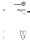
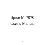
2.3.2 Serial Interface
A serial interface mimics the serial peripheral present on a generic computer. The registers
of our serial interfaces are shown in Figure 3. The SPEED and LINE CONTROL registers are
used to set the interface parameters (bit rate, number of data bits, etc.); the receiver bu er
register (RxDATA) holds incoming data, while the transmitter bu er register (TxDATA) holds
ougoing data. The STATUS register signals the presence of new data in the receiver bu er
register, and the completion of the transmission of the data held in the transmitter bu er
register. These events can be signaled by an interrupt request with a proper initialization
of the INT CONTROL register.
The actual working of a serial interface can be seen by connecting it to a suitable
device: in our system, a serial interface can be connected to a real or a pseudo tty of the
Unix host, or to a TCP virtual circuit where a user can telnet into.
7
Parity
0 0 odd
0 1 even
1 - none
Stop bits
0
1
1
2
SPEED
TYPE
LINE_CONTROL
STATUS
Data bits
00 5
01 6
10 7
11 8
TxREADY
RxREADY
TxDATA
INT_CONTROL
RxDATA
RxINT_ENABLE
TxINT_ENABLE
Figure 3: Serial interface registers
2.3.3 Disk interface
In the earlier days of computing, interfacing to disk drives and other mass-storage devices
was complicated by the need of using the main processor to control all the details of the
operation of the device. The most time critical functions were performed in hardware
(e.g. serial/parallel conversion), but other functions, such as seeking to the right cylinder,
waiting for the appropriate sector to come under the head, and checking for the correct
transfer of data were performed, in part or completely, by the main processor. In recent
years, however, all the details of dealing with the hardware have been masked o by the
controller embedded on disk drives [4], so that the main processor has little more to do
than asking the drive to read/write to a given cylinder/head/sector and waiting for the
operation to complete.
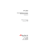
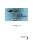
Our model of the disk subsystem re ects this way of operating; thus the registers of
the disk interface are those shown in Figure 4: a few registers are used to select the active
cylinder/head/sector, while an additional register is used to ask the interface to perform
a speci c command (write or read a sector).
Writing a sector involves lling the registers (CYLINDER L, CYLINDER H, HEAD, SECTOR)
with the appropriate values, issuing the WRITE command via the CONTROL register, and
transferring 512 bytes (the new content for the sector) to a bu er internal to the disk
controller. This data transfer is achieved by outputting every byte into the DATA register
of the disk interface. The controller will then start writing on the media and signal the
completion of the operation to the interface, which in turn sets the READY bit in the status
register, and possibly sends an interrupt request.
In order to read a sector, registers must be initialized as above, and a READ command
8
CYLINDER_L
TYPE
CYLINDER_H
STATUS
ERROR
READY
HEAD
SECTOR
DATA
CONTROL
INT_ENABLE
WRITE/READ
Figure 4: Disk interface registers
must be issued via the CONTROL register. The disk controller will then read the desired
sector from the media into an internal bu er, and signal the completion of the operation
to the interface, which in turn sets the READY bit in the status register, and possibly sends
an interrupt request. At this time, the content of the sector can be transferred to memory
by inputting 512 bytes from the DATA register.
3 Using the simulator
Students start using the tool presented in this paper with little knowledge about computers. As a consequence, our software has a menu driven interface which assists the user in
all phases. There are two version of the simulator, one aimed to alphanumeric terminals,
the other which can be used from a graphic terminal running X. In both cases, the user is
presented with a main menu which shows di erent options such as editing and compiling
a program on the host, and loading, running and debugging the program on the target.
System programs (editor, compiler, debugger) are invoked, when necessary, to execute the
desired functions. Care has been taken to make the system easy to use even to the rst
time user. Thus, a variety of help screens is available during all phases of the operation,
giving information on the architecture of the system, the language syntax, the available
primitives, etc. (see Figure 5).
After the simulator has been started, a lab session typically consists of the following
phases:
Edit One of the system editors is invoked for the editing of an existing or a new le. In
case of a new le, the user is supplied a template le in order to ease the writing of
the new code.
9
Figure 5: The main window of the simulator on the host console while editing a le. Popup menus in the main window (in background) allow the selections of various commands.
A help screen is shown in foreground.
Compile The system compiler is invoked to this purpose, and the user program is linked
with all the required libraries in a transparent way.
Load and execute The user program is loaded onto the target, and started on it. When
the program is running on the target, the host console remains active, constituting
an additional I/O device. The program on the target can communicate with this
device by using some library routines such as printf() and getchar().
When run on a windowing system, the screen of the user workstation will show one
window for each serial line in the target, plus one acting as the host console (Figure 6). An additional window can optionally be created to show the contents of
the internal registers of all the target's interfaces, and the status of the interrupt
and privilege ags of the target processor. The presence of this window should
considerably help the user during the debugging of the program (at the expense of
a considerable slowdown in the execution of programs, because of the amount of
activity which is done on every single I/O operation). When even this is insucient,
a system debugger can be used for a more in-depth analysis of the user program.
In order to carry on special experiments, the user might want to con gure the target
in some special way, e.g. by rede ning the size of the disk, or by hardwiring some of the
10
Figure 6: A screen dump of a the system while running a user program on four serial
ports. The additional debugging window is not shown.
11
serial lines of the target to physical or logical devices. To this purpose, a con guration
menu can be invoked which asks the disk size and geometry (cylinders, heads and sectors),
the number of serial interfaces (1 to 9) and, for each serial interface, the type of device
it must be connected to. Possible devices include a real serial line (e.g. /dev/tty01), a
pseudo tty which in turn is automatically connected with an xterm (e.g. xterm -display
somehost:0), or a TCP virtual circuit on a user-speci ed TCP port (e.g. tcp-6590).
3.1 Programming examples
One of the main purposes of our system is to emphasize that a high level language such
as C is well suited to the development of system software. User programs are thus written
in C language. They must include a header le (emu.h) which de nes symbolic constants
with the base addresses of all interfaces in I/O space, and the o set of the internal registers
locally to each interface. As an example, the address of the status register of the third
serial interface can be expressed as SERIAL3+STATUS. The entry point of the user program
must be called boot(). The user program is started by invoking this function with the
target in privileged state and with interrupts disabled.
In the Appendix we present a couple of sample programs which show how to program
our system. Program 1 shows the concurrent use of four serial interfaces and the timer.
More precisely, the timer is initialized to interrupt cyclically every 10 seconds; on every
interrupt, the handler will write the character 'x' to the rst serial interface. Serial
interfaces 2 and 3 are programmed to interrupt on each received character: the pertinent
handler will read the character from the interface and echo it to the other interface.
All of the above activities are completely interrupt driven and run concurrently on the
processor. The main program, after initializing the interfaces, will lower the privilege and
starts sending lowercase letters to the fourth serial interface (this is done via a trap(),
as direct access to peripherals is not allowed in user state). As the main program runs
in user state, it has no direct access to the I/O instructions: thus it must use a software
interrupt to perform the I/O activities involved in sending a character.
The second program shows a couple of trap handlers that can be used to read and
write a sector on the disk subsystem. The two handlers can be invoked as trap(0x12) and
trap(0x13) from some library routines which perform disk I/O. They read the parameters
from a common data area, initialize the I/O registers of the disk interface, then wait for
an interrupt from the disk to signal the completion of the operation.
4 Implementation details
Our simulator is completely written in C language, and it is designed to run on Unix systems. It requires interprocess communication capabilities (we use Unix or TCP sockets [6])
12
and a mechanism for the noti cation of asynchronous events (we use Unix signals). No
graphic capabilities or a windowing system are required for the alphanumeric version of
the program2. The availability of an X terminal, however, makes both the software development phase and the running of the program much more friendly, as multiple windows
can be shown on the screen at once.
The simulator is actually made of two separate components, shown in Figure 7: a user
process, which executes user code, and a system process, which simulates I/O peripherals
and the interrupt and privilege ags, and protects accesses to privileged resources. The
two processes are well separated and communicate by means of a pair of Unix virtual
circuits, which guarantee a clean interface between the two parts and allow for an easy
monitoring of the evolution of the system.
User programs running on the target are executed by the user process, as far as \normal" instructions are concerned. Extended instructions (those shown in Table 1), are
executed by the system process via an RPC mechanism: a message is sent to the system
process with the indication of the operation to be performed, and a reply is possibly received when necessary. Note that, while extended instructions are executed synchronously,
they might also trigger the start of some asynchronous activity on the system process. This
is the case, as an example, for I/O instructions, whose execution might also cause some
peripheral to perform actual I/O: this is accomplished by the system process which, depending on the contents of the status registers, will simulate the evolution of the peripheral
and execute the appropriate actions. Whenever an interface needs to generate an interrupt, the system process is informed, and dispatches a signal() to the user process. The
latter receives the request and, if interrupts are enabled, requests the type to the system
process, and executes the correct handler for the interrupt. The performance of the system
is quite good, as there is no penalty in running programs in this system except when one
of the instructions in Table 1 is involved.
5 Conclusions
We have described the structure of a simulated computer which can be used to support
teaching of computer architecture. Our system simulates a complete computer consisting
in a CPU with interrupt and protection mechanisms, and a set of common peripherals
such as serial interfaces, a disk unit and a timer. The system can be programmed in a
high level language such as C, while still providing full access to the low level features of
the processor. The simulator described in this paper eases the exploration of important
areas in computer architecture, such as peripheral handling and the interrupt mechanism,
and allows students to concentrate on the real problems instead of being distracted by
2
Of course, in this case it becomes harder to interact with the various serial lines of the system.
13
RPC
System
process
User
process
signal()
Figure 7: The internal structure of the simulator.
uninteresting details of the hardware.
The entire software development, from the coding phase to the execution of the programs, is completely driven by menus to make the use of the simulator more friendly.
This, together with the use of a high level language, and the large set of peripherals which
are simulated, makes it possible to develop even complex applications with limited e ort,
and thus makes lab sessions more interesting and productive. As an example of a complex
application, a complete multitasking, preemptive kernel is being ported to this simulator.
The program described in this paper runs on a variety of Unix-like systems, with or
without a windowing system, and is available from the authors.
References
[1] P.Corsini, L.Rizzo, SSCSSC: A Tool for the Teaching of Digital Circuits, IEEE Trans.
on Education, vol.34 n.1, Feb. 1991, pp.70-75
[2] P.Corsini, C.A.Prete, SYNCONET: A tutor for the synthesis of combinational networks via Karnaugh Maps and Prime Implicant Chart, Education and Application
Computer Technology, 23-25 Ottobre 1988, pp. 687-692.
[3] Digital Equipment Corporation, Alpha Architecture Handbook, Digital Equipment Corporation, 1992
[4] IDE disk speci cation, see for example Summit AT Intelligent Disk Drives Product
Manual, Conner Peripherals, Inc., 1992
[5] B.W. Kernighan, D.M. Ritchie, The C Programming Language, Second Edition, Prentice Hall, Englewood Cli s, NJ, 1988
14
[6] S.J.Leer, M.K.McKusick, M.J.Karels, J.S.Quarterman, The Design and Implementation of the 4.3BSD Unix Operating System, Addison Wesley, Reading, MA, 1989
[7] LSI Logic, LR3000 and LR3000A MIPS RISC Microprocessor User's Manual, LSI
Logic Corporation, 1990/1991
[8] J.K. Ousterhout, Tcl and the Tk Toolkit, Addison Wesley, Reading, Ma, 1994 (to
appear)
15
Appendix
Here we present the listing of the two sample programs described in the paper.
Program 1
#include <emu.h>
void timer_handler() {
out(SERIAL1+TxDATA, 'x');
iret();
}
void serial2_handler() {
byte c;
c=in(SERIAL2+RxDATA);
out(SERIAL3+TxDATA, c);
iret();
}
void serial3_handler() {
byte c;
c=in(SERIAL3+RxDATA);
out(SERIAL2+TxDATA, c);
iret();
}
byte data_out;
void trap_handler() {
sti();
while ( (in(SERIAL4+STATUS) & 0x2) == 0) ;
out(SERIAL4+TxDATA, data_out);
iret();
}
boot() {
cli();
interrupt_vector[0x09] = timer_handler;
out(TIMER+TYPE, 0x09 );
out(TIMER+ TIME_L, 1000 % 256 );
out(TIMER+ TIME_H, 1000 / 256 );
out(TIMER+ CONTROL, 0x07);
16
out(SERIAL1+SPEED, 0x0D); /* serial1: 9600 baud */
out(SERIAL1+LINE_CONTROL, 0x13); /* no par, 1stop, 8 bit data */
out(SERIAL1+CONTROL, 0 ); /* no interrupts */
interrupt_vector[0x02] = serial2_handler;
out(SERIAL2+TYPE, 0x02 );
out(SERIAL2+SPEED, 0x0D); /* serial 2: 9600 baud */
out(SERIAL2+LINE_CONTROL, 0x13); /* no par, 1stop, 8 bit data */
out(SERIAL2+CONTROL, 0x01); /* rx interrupt */
interrupt_vector[0x03] = serial3_handler;
out(SERIAL3+TYPE, 0x03 );
out(SERIAL3+SPEED, 0x0D); /* serial 3: 9600 baud */
out(SERIAL3+LINE_CONTROL, 0x13); /* no par, 1stop, 8 bit data */
out(SERIAL3+CONTROL, 0x01); /* rx interrupt */
interrupt_vector[0x60] = trap_handler;
sti();
clp();
for(i='a';; i= (i=='z' ? 'a' : i++ ) {
data_out=i;
trap(0x60);
}
}
Program 2
byte buffer[512];
byte head;
byte sect;
byte cyl_h;
byte cyl_l;
void disk_handler()
{
sync=1;
iret();
}
void trap_12_handler() /* disk read */
{
int i;
sync=0;
17
out(DISK+HEAD, head);
out(DISK+SECTOR, sect);
out(DISK+CYLINDER_L, cyl_l);
out(DISK+CYLINDER_H, cyl_h);
out(DISK+COMMAND, 0x11); /* read + int.enable */
sti();
while (sync == 0) ;
cli();
for(i=0; i<512; i++) buffer[i]=in(DISK+DATA);
iret();
}
void trap_13_handler() / * disk write */
{
int i;
sync=0;
out(DISK+HEAD, head);
out(DISK+SECT, sect);
out(DISK+CYLINDER_L, cyl_l);
out(DISK+CYLINDER_H, cyl_h);
out(DISK+COMMAND, 0x11); /* write + int.enable */
for(i=0; i<512; i++) out(DISK+DATA, buffer[i]);
sti();
while (sync == 0) ;
iret();
}
boot()
{
cli();
interrupt_vector[0x0A]=disk_handler;
out(DISK+TYPE,0x0A);
interrupt_vector[0x12]=trap_12_handler;
interrupt_vector[0x13]=trap_13_handler;
sti();
clp();
...
}
18