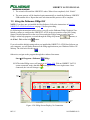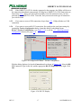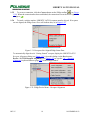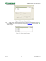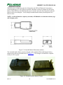
1
LIBERTY™ LATUS™ LIBERTY™ LATUS™ USER MANUAL URM05PH184 REV. E NOVEMBER 2013 LIBERTY LATUS MANUAL Copyright © 2003- 2013 by Alken, Inc., dba Polhemus Colchester, Vermont, U.S.A. All rights reserved. No part of this publication may be reproduced, stored in a retrieval system, or transmitted, in any form or by any means, mechanical, photocopying, recording or otherwise, without the prior written permission of Polhemus. No patent liability is assumed with respect to the use of the information contained herein. While every precaution has been taken in the preparation of this manual, Polhemus assumes no responsibility for errors or omissions. Neither is any liability assumed for damages resulting from use of the information contained herein. 3SPACE®, LIBERTY™ and LIBERTY LATUS™ are trademarks of Polhemus. Windows® is a registered trademark of Microsoft Corporation. FCC Statement This equipment has been tested and found to comply with the limits for a Class A digital device, pursuant to part 15 of the FCC Rules. These limits are designated to provide reasonable protection against interference when the equipment is operated in a commercial environment. This equipment generates, uses, and can radiate radio frequency energy and, if not installed and used in accordance with the instruction manual, may cause interference to radio communications. Operation of this equipment in a residential area is likely to cause interference in which case the user will be required to correct the interference at the user’s own expense. Medical Device Use Polhemus is a Good Manufacturing Practices (GMP) Contract Manufacturer under U.S. FDA Regulations. We are not a manufacturer of Medical Devices. Polhemus systems are not certified for medical or bio-medical use. Any references to medical or bio-medical use are examples of what medical companies have done with the Products after they have obtained all necessary or appropriate medical certifications. The end user/OEM/VAR/Distributor must comply with all pertinent FDA/CE regulations pertaining to the development and sale of medical devices and all other regulatory requirements. EC – Declaration of Incorporation This Product Complies with the following European Community Directives: 89/336/EEC as amended by 92/31/EEC 73/23/EEC Low Voltage as amended by 93/68/EEC The following standards were used to verify compliance with the directives: EMC: IEC 61326-1:1997+A1:1998 / EN 61326-1:1997+A1:1998 CCISPR 11:1990 / EN 55011:1991-Group 1 Class A IEC 6100-4-2:1995+A1:1998 / EN 61000-4-2:1995 (ESD 4kV CD, 8kV AD) IEC 6100-4-3:1995 / EN 61000-4-3:1995 (3V/m 80% AM) IEC 6100-4-4:1995 / EN 61000-4-4:1995 (0.5kV line-line, 1kV line-earth) IEC 6100-4-6:1995 / EN 61000-4-6:1995 (3V 80% AM, power line) Australia/New Zealand: AS/NZS 2064.1 Safety: IEC 61010-1:1990+A1:1992+A2:1995 / EN 61010-1:1993+A2:1995 REV. E i NOVEMBER 2013 LIBERTY LATUS MANUAL Safety Notices This apparatus has been designed and tested in accordance with IEC Publication 1010, Safety Requirements for Measuring Apparatus, and has been supplied in a safe condition. This is a Safety Class I instrument (provided with terminal for protective grounding). Before applying power, verify that the correct safety precautions are taken (see the following warnings). Warnings • • • • • • Before turning on the instrument, be aware that the mains plug shall only be inserted in a socket outlet provided with a protective ground contact. You must not negate the protective action by using an extension cord (power cable) without a protective conductor (grounding). Grounding one conductor of a two-conductor outlet is not sufficient protection. Whenever it is likely that the ground protection is impaired, you must make the instrument inoperative and secure it against any unintended operation. This instrument contains no user serviceable parts. Do not attempt to service the unit. Return it to Polhemus for repair. Do not perform any unauthorized modification to the instrument. Do not operate the instrument in the presence of flammable gasses or fumes. Operation of any electrical instrument in such an environment constitutes a definite safety hazard. Do not use the instrument in a manner not specified by the manufacturer. To Clean the Instrument If the instrument requires cleaning: (1) Remove power from the instrument. (2) Clean the external surfaces of the instrument with a soft cloth dampened with a mixture of mild detergent and water. Make sure that the instrument is completely dry before reconnecting it to a power source. HANDLING RECOMMENDATIONS FOR LITHIUM ION OR LITHIUM POLYMER BATTERIES In order to obtain optimum performance, please follow the warnings and safety instructions listed in the handling precautions below. • Keep Lithium ion/Lithium polymer batteries away from children. If a battery is swallowed promptly call your doctor. • Do not allow any Lithium ion/Lithium polymer battery to come into contact with water or liquid of any kind. Do not leave the battery near flames, heaters, (microwave) ovens, stoves, fireplaces or other hightemperature locations. Excessive heat could cause the battery to deteriorate. Do not heat the battery or throw it into a fire. This can damage the safety vent and cause the electrolyte to catch fire. • Do not leave the battery in a hot condition like strong direct sunlight, inside automobiles behind the windscreen, etc. This can overheat the cell and will reduce the battery’s performance. • Do not damage the battery in any way by nailing, hammering, crushing, etc. This can cause the cell to leak and/or to short circuit internally. • Do not combine batteries of different capacities, types or brands. • If a battery leaks or emits a strange odor during use or storage, stop using the cell immediately. Leaking electrolytes are flammable. • If any fluid that has leaked from the battery comes into contact with skin or clothing, rinse with tap water or other clean water immediately. Contact with skin can cause irritation or burns. • If fluid from a battery gets into a person’s eye, rinse the eye immediately with clean water and seek medical attention promptly. Do not rub the eye. REV. E i NOVEMBER 2013 LIBERTY LATUS MANUAL Table of Contents SAFETY NOTICES................................................................................................................................................................... I WARNINGS .................................................................................................................................................................................................... I TO CLEAN THE INSTRUMENT .......................................................................................................................................................................... I 1 GETTING STARTED ..................................................................................................................................................... 1 1.1 1.2 1.3 LIBERTY LATUS MODELS .............................................................................................................................................................. 1 SETTING UP LIBERTY LATUS......................................................................................................................................................... 2 CHARGING AND USING LIBERTY LATUS MARKER BATTERIES........................................................................................................ 7 1.3.1 Charging the Extended Marker Battery ................................................................................................................................. 7 1.3.2 Charging the Standard Marker Battery (discontinued) ........................................................................................................ 10 1.3.3 Using Wireless Markers ....................................................................................................................................................... 14 1.4 INSTALLING LIBERTY LATUS HOST SOFTWARE ........................................................................................................................... 15 1.4.1 USB Driver Installation........................................................................................................................................................ 15 1.5 USING THE POLHEMUS PIMGR GUI .................................................................................................................................................. 16 1.6 USING THE LIBERTY LATUS ASCII INTERFACE ........................................................................................................................... 22 1.7 EXPERIMENT WITH LIBERTY LATUS DATA .................................................................................................................................. 24 2 COMPONENT DESCRIPTION ................................................................................................................................... 25 2.1 SYSTEM ELECTRONICS UNIT (SEU) .................................................................................................................................................. 25 2.1.1 Receptor Ports (4 / 8 / 12 / 16) ............................................................................................................................................. 25 2.1.2 LED Indicator ...................................................................................................................................................................... 25 2.1.3 External Sync I/O ................................................................................................................................................................. 25 2.1.4 RS-232 I/O............................................................................................................................................................................ 26 2.1.5 USB I/O ................................................................................................................................................................................ 26 2.1.6 RS-422 I/O............................................................................................................................................................................ 26 2.1.7 Video Sync ............................................................................................................................................................................ 27 2.2 RECEPTOR ........................................................................................................................................................................................ 27 2.3 EXTENDED MARKER ........................................................................................................................................................................ 27 2.4 STANDARD MARKER (DISCONTINUED) ............................................................................................................................................. 29 2.5 LIBERTY LATUS STANDARD MARKER BATTERY CHARGER (DISCONTINUED) ............................................................................... 29 3 SYSTEM OPERATION ................................................................................................................................................ 31 3.1 3.2 3.3 I/O CONSIDERATIONS ....................................................................................................................................................................... 31 POWERING UP LIBERTY LATUS ................................................................................................................................................... 31 RECEPTOR SETUP ............................................................................................................................................................................. 32 3.3.1 Receptor Positioning and Setup ........................................................................................................................................... 32 3.3.2 Receptor Alignment .............................................................................................................................................................. 33 3.3.2.1 Automatic Receptor Alignment ...................................................................................................................................... 34 3.3.2.2 Manual Receptor Alignment ........................................................................................................................................... 39 3.3.2.3 Saving Receptor Alignments ........................................................................................................................................... 41 3.3.3 Reference Frame Setup ........................................................................................................................................................ 42 3.4 MARKER OPERATION ....................................................................................................................................................................... 43 3.4.1 Marker Launch and Unlaunch ............................................................................................................................................. 43 3.4.1.1 Manual Marker Launch ................................................................................................................................................... 44 3.4.1.2 Manual Marker Unlaunch ............................................................................................................................................... 45 3.4.1.3 Automatic Marker Launch and Unlaunch ....................................................................................................................... 46 3.4.2 Marker Installation .............................................................................................................................................................. 47 3.5 OPTIMIZATION AND UPDATE RATE ................................................................................................................................................... 48 3.5.1 Optimization Mode ............................................................................................................................................................... 48 3.5.2 Update Rate.......................................................................................................................................................................... 49 3.6 OUTPUT CONSIDERATIONS ............................................................................................................................................................... 50 3.6.1 Adaptive Filters .................................................................................................................................................................... 50 3.6.2 Increment.............................................................................................................................................................................. 50 3.7 CONFIGURATION CHANGES .............................................................................................................................................................. 51 3.8 CHARGING MARKER BATTERIES ....................................................................................................................................................... 51 4 LIBERTY LATUS SYSTEM COMMANDS ............................................................................................................... 53 4.1 4.2 OVERVIEW ....................................................................................................................................................................................... 53 COMMAND SYNTAX ......................................................................................................................................................................... 53 4.2.1 Notation ................................................................................................................................................................................ 53 4.2.2 Command Format Notes ...................................................................................................................................................... 54 Station Wildcard ............................................................................................................................................................................. 54 Default Parameters .......................................................................................................................................................................... 54 REV. E ii NOVEMBER 2013 LIBERTY LATUS MANUAL 4.2.3 Response Format Notes ........................................................................................................................................................ 55 ASCII .............................................................................................................................................................................................. 55 Binary ............................................................................................................................................................................................. 55 Error Responses .............................................................................................................................................................................. 56 4.3 LIBERTY LATUS USER COMMAND SET SUMMARY ....................................................................................................................... 57 4.4 LIBERTY LATUS ERROR CODE SUMMARY.................................................................................................................................... 58 4.5 COMMAND REFERENCE .................................................................................................................................................................... 59 4.5.1 Configuration Commands .................................................................................................................................................... 59 ‘B’ – Boresight ..................................................................................................................................................................... 60 ‘F’ – Output Format ............................................................................................................................................................. 62 ‘G’ – Marker Reference Frame ............................................................................................................................................ 63 ‘M’ – Installed Markers ........................................................................................................................................................ 65 ‘O’ – Output Data List.......................................................................................................................................................... 67 ‘R’ – Update Rate ................................................................................................................................................................. 69 ‘U’ – Set Units...................................................................................................................................................................... 70 ‘X’ – Position Filter Parameters ........................................................................................................................................... 71 ‘Y’ – Attitude Filter Parameters ........................................................................................................................................... 73 ‘Z’ – Set Sync Mode ............................................................................................................................................................ 75 ‘^E’ – Set Echo Mode .......................................................................................................................................................... 76 ‘^G’ – Set Autolaunch Criteria ............................................................................................................................................. 77 ‘^N’ – Increment .................................................................................................................................................................. 79 ‘^O’ – RS-232 Port Configuration ....................................................................................................................................... 80 ‘^R’ – Optimization Mode ................................................................................................................................................... 82 ‘^S’ – Startup Receptor Alignment Configuration ............................................................................................................... 84 ‘^U’ – Active Marker Map ................................................................................................................................................... 85 ‘^X’ – Operational Configuration ID ................................................................................................................................... 87 ‘@A’ – Autolaunch Mode .................................................................................................................................................... 89 ‘@B’ – USB Buffering Mode .............................................................................................................................................. 90 ‘@N’ – AutoIncrement......................................................................................................................................................... 92 4.5.2 Operational Commands ....................................................................................................................................................... 93 ‘A’ – Set Alignment Mode ................................................................................................................................................... 94 ‘C’ – Continuous Print Output ............................................................................................................................................. 96 ‘L’ – Launch Marker ............................................................................................................................................................ 97 ‘N’ – Launched Marker ID ................................................................................................................................................... 98 ‘P’ – Single Data Record Output .......................................................................................................................................... 99 ‘Q’ – Reset Counters .......................................................................................................................................................... 101 ‘^A’ – Receptor Alignments............................................................................................................................................... 102 ‘^B’ – Aligned Receptors Map ........................................................................................................................................... 104 ‘^D’ – Alignment Criteria .................................................................................................................................................. 105 ‘^F’ – Force Alignment ...................................................................................................................................................... 106 ‘^K’ – Save Operational Configuration .............................................................................................................................. 107 ‘^L’ – Unlaunch Marker ..................................................................................................................................................... 108 ‘^P’ – Phase Step ................................................................................................................................................................ 109 ‘^V’ – WhoAmI ................................................................................................................................................................. 110 ‘^W’ – Set Operational Configuration................................................................................................................................ 112 ‘^Y’ – Initialize System...................................................................................................................................................... 113 ‘^Z’ – Read Operational Configuration .............................................................................................................................. 114 ‘@S’ – Signal Strength ....................................................................................................................................................... 117 APPENDIX A. APPENDIX B. TERMS/ACRONYMS ....................................................................................................................................A-1 SYSTEM OUTPUT DATA RECORDS ............................................................................................................. B-9 ASCII FORMAT ..................................................................................................................................................................................... B-9 BINARY FORMAT .............................................................................................................................................................................. B-10 APPENDIX C. APPENDIX D. APPENDIX E. REV. E LIMITED WARRANTY AND LIMITATION OF LIABILITY .............................................................................C-1 SPECIFICATIONS .........................................................................................................................................D-1 CUSTOMER SERVICE .................................................................................................................................. E-1 iii NOVEMBER 2013 LIBERTY LATUS MANUAL List of Figures Figure 1-1: LIBERTY LATUS ............................................... 1 Figure 1-2: LIBERTY LATUS Rear Panel .............................3 Figure 1-3: Receptor and Receptor Connector Cord ...............3 Figure 1-4: Receptor/Marker Test Setup.................................4 Figure 1-5: Marker Number Label .......................................... 4 Figure 1-6: Power Connector .................................................. 4 Figure 1-7: USB Cable Connection ........................................ 5 Figure 1-8: RS-232 Cable Connection ....................................6 Figure 1-9 Extended Marker Battery ......................................7 Figure 1-10 Extended Marker Battery Charger .......................7 Figure 1-11 Placing Extended Marker Batteries Into Charger 8 Figure 1-12 Extended Marker Battery Tab Orientation ..........8 Figure 1-13 Extended Marker Battery Insertion .....................9 Figure 1-14 Extended Marker: Successful Battery Installation ...................................................................................... 9 Figure 1-15 Standard Marker Battery (Discontinued)........... 10 Figure 1-16: Standard Marker Battery Charging Components .................................................................................... 10 Figure 1-17: Standard Marker: Placing Batteries Into Charger .................................................................................... 11 Figure 1-18: Standard Marker Battery Charger Power On ... 11 Figure 1-19: Standard Marker Batteries Charging ................ 11 Figure 1-20: Standard Marker: Preparing To Remove The Battery ........................................................................ 12 Figure 1-21: Standard Marker: Lifting The Battery .............. 12 Figure 1-22: Standard Marker: Spring Clip Improperly Seated .................................................................................... 13 Figure 1-23: Standard Marker: Proper Seating Of Spring Clip .................................................................................... 13 Figure 1-24: Standard Maker Battery Tab Orientation ......... 13 Figure 1-25: Standard Marker Battery Insertion ................... 14 Figure 1-26: Successful Standard Marker Battery Installation .................................................................................... 14 Figure 1-27: Marker Power Switch and LED ....................... 15 Figure 1-28: PiMgr Screen Display, No Connection ............ 16 Figure 1-29: PiMgr Device Menu – Tracker Configuration.. 17 Figure 1-30: RS-232 Display ................................................ 17 Figure 1-31: Receptors Not Aligned PiMgr Status Pane....... 18 Figure 1-32: PiMgr Device Menu – Receptor Alignment ..... 18 Figure 1-33: Receptor Alignment Dialog ............................. 19 Figure 1-34: Select Anchor Receptor ................................... 19 Figure 1-35: Start Auto Align .............................................. 20 Figure 1-36: Auto Align Confirmation Dialog ..................... 20 Figure 1-37: Aligned Receptor List ...................................... 21 Figure 1-38: Marker in PiMgr Status Pane ........................... 21 Figure 1-39: PiMgr Data Record Display (using marker 4) . 22 Figure 2-1: External Sync..................................................... 26 Figure 2-2: Receptor............................................................. 27 Figure 2-3: Extended Marker Dimensions (inches) .............. 28 Figure 2-4: Extended Marker Battery Charger ..................... 28 Figure 2-5: Standard Marker Dimensions (inches)............... 29 Figure 2-6: Standard Marker Battery Charger, Front View .. 30 Figure 2-7: Standard Marker Battery Charger and Power Pack, Rear View ........................................................ 30 Figure 3-1: Receptor ‘Serial’ Pattern (Top View) ................ 32 Figure 3-2: Receptor ‘Cluster’ Pattern (Top View) .............. 33 Figure 3-3: Example Staging Area ....................................... 33 Figure 3-4: HELP button location on Receptor Alignment dialog box .................................................................. 34 Figure 3-5: Select Anchor Receptor ..................................... 35 Figure 3-6: +X Hemisphere direction of marker .................. 35 Figure 3-7: Select Hemisphere ............................................. 36 Figure 3-8: Auto Align Criteria ............................................ 37 Figure 3-9: Auto Align Marker Starting Orientation ............ 37 Figure 3-10: Auto Align Receptor List................................. 38 Figure 3-11: Aligning Receptor............................................ 38 Figure 3-12: List of aligned receptors .................................. 39 Figure 3-13: Select Receptor for Manual Alignment ........... 40 Figure 3-14: Manually Align Receptor ................................ 41 Figure 3-15: Save or Erase Startup Alignment Data ............ 42 Figure 3-16: Select Launch Receptor ................................... 45 Figure 3-17: Marker Launch Orientation ............................. 45 Figure 3-18: Unlaunching a marker...................................... 46 Figure 3-19: Select marker to unlaunch ............................... 46 Figure 3-20: Autolaunch ...................................................... 47 Figure 3-21: Optimization Mode dialog box ........................ 49 Figure 3-22: Output Rate...................................................... 49 Figure 4-1: Euler Angles .................................................... A-6 DUE TO SOFTWARE AND HARDWARE MODIFICATIONS SCREEN OR PRODUCT EXAMPLES APPEARING IN THIS MANUAL MAY VARY SLIGHTLY FROM THE ACTUAL SCREENS OR PRODUCTS THE USER ACCESSES. REV. E iv NOVEMBER 2013 LIBERTY LATUS MANUAL List of Tables Table 1-1 System Status Indicators ..................................... 5 Table 2-1 LED Indicators ................................................. 25 Table 2-2 External Sync Pin-Outs .................................... 26 Table 2-3 RS-232 Pin-Outs............................................... 26 Table 3-1: Optimization Mode/Update Rate Summary..... 49 Table 4-1 ASCII Response Format ................................... 55 Table 4-2 Binary Response Format .................................. 56 Table 4-3 ‘B’ ASCII Response ......................................... 60 Table 4-4 ‘B’ Binary Response......................................... 60 Table 4-5 ‘F’ ASCII Response ......................................... 62 Table 4-6 ‘F’ Binary Response ......................................... 62 Table 4-7 ‘G’ ASCII Response ......................................... 64 Table 4-8 ‘G’ Binary Response ........................................ 64 Table 4-9 ‘M’ ASCII Response Header ............................ 65 Table 4-10 ‘M’ ASCII Response ...................................... 65 Table 4-11 ‘M’ Binary Response ...................................... 66 Table 4-12 Output Data Types .......................................... 67 Table 4-13 ‘O’ ASCII Response ....................................... 68 Table 4-14 ‘O’ Binary Response ...................................... 68 Table 4-15 ‘R’ ASCII Response ....................................... 69 Table 4-16 ‘R’ Binary Response....................................... 69 Table 4-17 ‘U’ ASCII Response ....................................... 70 Table 4-18 ‘U’ Binary Response ...................................... 70 Table 4-19 ‘X’ ASCII Response ....................................... 72 Table 4-20 ‘X’ Binary Response ...................................... 72 Table 4-21 ‘Y’ ASCII Response ....................................... 74 Table 4-22 ‘Y’ Binary Response ...................................... 74 Table 4-23 ‘Z’ ASCII Response ....................................... 75 Table 4-24 ‘Z’ Binary Response ....................................... 75 Table 4-25 ‘^E’ ASCII Response ..................................... 76 Table 4-26 ‘^E’ Binary Response ..................................... 76 Table 4-27 ‘^G’ ASCII Response ..................................... 77 Table 4-28 ‘^G’ Binary Response..................................... 77 Table 4-29 ‘^N’ ASCII Response ..................................... 79 Table 4-30 ‘^N’ Binary Response..................................... 79 Table 4-31 ASCII Baud Rate Values ................................ 80 Table 4-32 ASCII Parity Values ....................................... 80 REV. E Table 4-33 ‘^O’ ASCII Response .................................... 81 Table 4-34 ‘^O’ Binary Response .................................... 81 Table 4-35 Binary RS-232 Codes..................................... 81 Table 4-36 ‘^R’ ASCII Response ..................................... 83 Table 4-37 ‘^R’ Binary Response .................................... 83 Table 4-38 ‘^U[marker]’ ASCII Response ...................... 86 Table 4-39 ‘^U0’ ASCII Response................................... 86 Table 4-40 ‘^U’ Binary Output Format ............................ 86 Table 4-41 ‘^X’ ASCII Response .................................... 87 Table 4-42 ‘^X’ Binary Response .................................... 87 Table 4-43 ‘@A’ ASCII Response ................................... 89 Table 4-44 ‘@A’ Binary Response .................................. 89 Table 4-45 ‘@B’ ASCII Response ................................... 91 Table 4-46 ‘@B’ Binary Response .................................. 91 Table 4-47 ‘@N’ ASCII Response ................................... 92 Table 4-48 ‘@N’ Binary Response .................................. 92 Table 4-49 ‘N’ ASCII Response ...................................... 98 Table 4-50 ‘N’ Binary Response ...................................... 98 Table 4-51 ‘P’ ASCII Response ....................................... 99 Table 4-52 ‘P’ Binary Response....................................... 99 Table 4-53 ‘^A’ ASCII Response .................................. 103 Table 4-54 ‘^A’ Binary Output Format .......................... 103 Table 4-55 ‘^B’ ASCII Response ................................... 104 Table 4-56 ‘^B’ Binary Output Format .......................... 104 Table 4-57 ‘^D’ ASCII Response .................................. 105 Table 4-58 ‘^D’ Binary Output Format .......................... 105 Table 4-59 ‘^V’ ASCII Response .................................. 110 Table 4-60 ‘^V’<> Binary Response.............................. 110 Table 4-61 ‘^V[receptor]’ ASCII Response................... 110 Table 4-62 ‘^V[receptor]’ Binary Response .................. 110 Table 4-63 ‘^Z’ ASCII Response Header....................... 114 Table 4-64 ‘^Z’ ASCII Response ................................... 115 Table 4-65 ‘^Z’ Binary Response .................................. 116 Table 4-66 ‘@S’ ASCII Response ................................. 117 Table 4-67 ‘@S’ Binary Response ................................. 117 vi NOVEMBER 2013 LIBERTY LATUS MANUAL 1 Getting Started Congratulations on your purchase of Polhemus’ most innovative motion tracking system to date: The LIBERTY LATUS. This section of the manual is provided to help get your tracking system up and running quickly. It covers the basics of understanding and setting up the system to demonstrate its principles. However, this is meant only as a starting point to show that the system is operating properly before delving into more detailed setup. The remaining sections of this manual serve as a complete reference resource for LIBERTY LATUS operation. 1.1 LIBERTY LATUS Models The LIBERTY LATUS (Large Area Tracking Untethered System) is designed to track Position and Orientation (P&O) of mobile wireless Markers relative to a user-defined coordinate system referenced to a fixed array of special sensing units called Receptors. Receptors are cabled to the SEU (System Electronics Unit) and are arrayed over the motion tracking environment. They track the magnetic field signals emanating from the wireless battery-powered markers. The position and orientation of each marker is calculated and communicated from the SEU to a host computer via RS-232 or USB. Marker P&O is automatically aligned to a user-defined reference point relative to the receptor array. This user manual covers all LIBERTY LATUS models and configurations: • The LIBERTY LATUS base system supports four receptors and up to 12 wireless markers. This system is scalable to support up to 16 receptors to cover a larger physical area. All LIBERTY LATUS models are expansions on the basic LIBERTY system and are managed and configured similarly. However, in the very few circumstances where LIBERTY LATUS commands or operations differ, those differences are clearly noted in this manual. Figure 1-1: LIBERTY LATUS REV. E 1 NOVEMBER 2013 LIBERTY LATUS MANUAL 1.2 Setting Up LIBERTY LATUS The basic system consists of a System Electronics Unit (SEU), which requires at least one receptor, at least one marker with rechargeable Lithium ion/Lithium polymer battery, and a charger for the battery. Each processing board on the SEU can operate up to four receptors, and the SEU can be outfitted with up to four such boards for a total receptor capability of 16 receptors. Up to 12 unique markers can be operated simultaneously. NOTE: For the purpose of Getting Started, the following assumptions are made: • • • • • There is one receptor. There is one marker plus a spare marker battery. The marker batteries have been charged. See Charging and Using LIBERTY LATUS Marker Batteries on page 7. The host computer is running Windows XP or later, and has an available USB or COM port. The Polhemus PiMgr GUI should be installed on the host computer. See Installing LIBERTY LATUS Host Software on page 15 for instructions. 1.2.1 Unpack the LIBERTY LATUS SEU, receptors(s), marker(s), USB and RS-232 cables, LIBERTY LATUS Host Software CD, power cord and cables, and marker battery charger and power module. See Figure 1-1. 1.2.2 Set up the LIBERTY LATUS close to your host computer but within reach of the receptor cable length to the test area. 1.2.3 Examine the rear panel of the LIBERTY LATUS and review the locations of the receptor (sensor), power, RS-232, USB, and external sync ports. The layout of the rear panel is the same for all LIBERTY LATUS configurations. The only difference may be the number of receptor ports. See Figure 1-2. REV. E 2 NOVEMBER 2013 LIBERTY LATUS MANUAL RS-232 External Sync System Indicator USB Receptors Receptors Power Figure 1-2: LIBERTY LATUS Rear Panel 1.2.4 Connect the receptor. Uncoil a small length of the receptor cable and attach it to the “Sensor 1” connector on the SEU. Firmly engage and lock the receptor connector into place (See Figure 1-3). Tighten the two retaining screws to secure. Figure 1-3: Receptor and Receptor Connector Cord 1.2.5 Place the receptor head on a non-metallic surface. Dress the cable safely over to the SEU where it will not become entangled in a walkway. Place the charged* marker on the surface, to the rear of the receptor and about 10-12 inches away from the receptor. Make sure that the marker is oriented so that the +X direction is forward, toward the rear of the receptor. Refer to Figure 1-4. * NOTE: To charge a marker battery, refer to Charging and Using LIBERTY LATUS Marker Batteries on page 7. REV. E 3 NOVEMBER 2013 LIBERTY LATUS MANUAL Figure 1-4: Receptor/Marker Test Setup Make note of the marker number in your test setup. The marker number label is located on the top of the marker as shown in Figure 1-5. Figure 1-5: Marker Number Label 1.2.6 Identify the power entry module with the ON/OFF rocker switch on the rear panel. Ensure that this switch is in the OFF position (logic “0”, RIGHT) before inserting the AC power cord and applying 110/220 VAC. See Figure 1-6. Figure 1-6: Power Connector USB or RS-232 Communications • For USB, continue with step 1.2.7. REV. E 4 NOVEMBER 2013 LIBERTY LATUS MANUAL • For RS-232, skip to step 1.2.11. NOTE: Only one I/O mode (USB or RS-232) can be active at a time. If at any time the USB is connected between the powered tracking system and the host computer, USB will become operational automatically and any RS-232 connection will be disabled. To re-enable the RS-232 connection, the SEU must be reset or powered down and up with the USB cable disconnected. For USB Communications: 1.2.7 Identify the USB cable and insert it into the receptacle as shown in Figure 1-7. Connect the other end of the USB cable to the host computer. Figure 1-7: USB Cable Connection 1.2.8 Turn on the LIBERTY LATUS using the power switch located on the back panel of the SEU. A system status indicator located on the front and rear panels of the electronics unit should flash red for 5 to 10 seconds indicating self-test and setup. When these routines are completed, the indicator will display system status as described in Table 1-1. Table 1-1 System Status Indicators • Steady green System operational Detected receptor is ready for marker detection. • Solid red System operational Detected receptor is not ready (needs alignment). • Flashing red Failed self-test and set-up. 1.2.9 The host should detect the USB connection and respond with a “Found New Hardware” message. For step-by-step instructions for installing the USB drivers from the Host Software CD, refer to USB Driver Installation on page 15. 1.2.10 You are now ready to exercise the system. With the USB connection, you must use the Polhemus PiMgr GUI to do this. Continue to Using the Polhemus PiMgr GUI on page 16 to begin. For RS-232 Communications: 1.2.11 Locate the RS-232 cable and insert it into the receptacle as shown in Figure 1-8. REV. E 5 NOVEMBER 2013 LIBERTY LATUS MANUAL Most PC hosts have a 9 pin, male “D” type connector for COM1. If you are using COM1, plug the remaining end of the cable into the COM1 port of the host PC, engage, and secure in place by tightening the two retaining screws. If your host computer has a 25 pin “D” connector for the RS-232 port, you will need a 9 to 25 pin “D” connector adapter with the proper genders. Note that this adapter must not compromise the NULL MODEM sense of your cable. Figure 1-8: RS-232 Cable Connection 1.2.12 You are now ready to exercise the system. • • REV. E To use the Polhemus PiMgr GUI, continue to Using the Polhemus PiMgr GUI on page 16. To use LIBERTY LATUS’ ASCII interface through the Windows HyperTerminal program, refer to Using the LIBERTY LATUS ASCII Interface on page 22. 6 NOVEMBER 2013 LIBERTY LATUS MANUAL 1.3 Charging and Using LIBERTY LATUS Marker Batteries 1.3.1 Charging the Extended Marker Battery Figure 1-9 Extended Marker Battery 1.3.1.1 Locate the batteries and the charger of the extended marker; see Figure 1-10. Figure 1-10 Extended Marker Battery Charger 1.3.1.2 Slip the batteries into the receptacles atop the charger; See Figure 1-11. REV. E 7 NOVEMBER 2013 LIBERTY LATUS MANUAL Figure 1-11 Placing Extended Marker Batteries Into Charger 1.3.1.3 To install the battery into the marker, orient the battery so that the two slots of battery contact is toward the marker pins (see Figure 1-12). Figure 1-12 Extended Marker Battery Tab Orientation Tip the battery at an angle and insert tabs in marker slots (see Figure 1-13). REV. E 8 NOVEMBER 2013 LIBERTY LATUS MANUAL Figure 1-13 Extended Marker Battery Insertion Figure 1-14 Extended Marker: Successful Battery Installation REV. E 9 NOVEMBER 2013 LIBERTY LATUS MANUAL 1.3.2 Charging the Standard Marker Battery (discontinued) Figure 1-15 Standard Marker Battery (Discontinued) 1.3.2.1 Locate the batteries, the charger, and the charger’s power module and power cord; see Figure 1-16. Figure 1-16: Standard Marker Battery Charging Components Slip the two batteries into any two of the receptacles atop the charger; see Figure 1-17. REV. E 10 NOVEMBER 2013 LIBERTY LATUS MANUAL Figure 1-17: Standard Marker: Placing Batteries Into Charger 1.3.2.2 Plug the power module into the rear of the charger and then into the power mains as depicted in Figure 1-18. Figure 1-18: Standard Marker Battery Charger Power On 1.3.2.3 Turn on the power switch on the rear of the charger. The green power ON indicator will illuminate. The two red “charging” LED’s where the batteries are inserted will also illuminate (see Figure 1-19). The other two “charging” LED’s will flash on and off and can be disregarded. Figure 1-19: Standard Marker Batteries Charging REV. E 11 NOVEMBER 2013 LIBERTY LATUS MANUAL 1.3.2.4 Total charging time of up to 2.5 hours may be required, depending on the initial charge status. Each charging LED will extinguish when the battery is fully charged. 1.3.2.5 To remove the battery, place your middle finger on one side and thumb on the other of the battery charger (see Figure 1-20). Figure 1-20: Standard Marker: Preparing To Remove The Battery Then pull the retaining clip back using the nail of your index finger, and insert the charged battery into the marker (see Figure 1-21). Figure 1-21: Standard Marker: Lifting The Battery Be certain that the spring tab on the battery pack seats fully into the marker base. A slight push down and forward on the spring tab with your forefinger will ensure that good battery contact will result (see Figure 1-22 and Figure 1-23). This same procedure should be employed when removing the battery from either a marker or the battery charger. REV. E 12 NOVEMBER 2013 LIBERTY LATUS MANUAL Figure 1-22: Standard Marker: Spring Clip Improperly Seated Figure 1-23: Standard Marker: Proper Seating Of Spring Clip 1.3.2.6 To install the battery into the marker, orient the battery so that the two tabs are toward the two corresponding slots in the marker (see Figure 1-24). Figure 1-24: Standard Maker Battery Tab Orientation REV. E 13 NOVEMBER 2013 LIBERTY LATUS MANUAL Tip the battery at an angle and insert tabs in marker slots (see Figure 1-25). Figure 1-25: Standard Marker Battery Insertion Then push the battery down into position on the marker. Be sure the retaining clip “clicks” into place so that the battery will not disengage during use (see Figure 1-26). Again, this same procedure should be employed when installing the battery into either a marker or the battery charger. Figure 1-26: Successful Standard Marker Battery Installation 1.3.3 Using Wireless Markers Find the small power switch on one end of the marker (Figure 1-27). Slide it ON (away from the LED) and observe that the LED power indicator next to the switch illuminates briefly, indicating that the marker is live. The LED illuminates only briefly to conserve power. A fully charged standard battery should operate for up to 2 continuous hours. A fully charged extended marker battery should operate for 6 hours or more. 1.3.3.1 Note: As will all batteries: capacity (run-time) will diminish over time due to battery age and charging cycles. REV. E 14 NOVEMBER 2013 LIBERTY LATUS MANUAL OFF → ON LED POWER SWITCH Figure 1-27: Marker Power Switch and LED When the battery is nearing complete discharge, the marker’s LED power indicator will illuminate continuously; the battery should be replaced or recharged immediately. 1.3.3.2 1.4 Installing LIBERTY LATUS Host Software NOTE: LIBERTY LATUS Host Software is intended to be installed on a computer running Windows® XP or later. 1. Insert the LIBERTY LATUS Host Software CD-ROM into your computer’s CD-ROM drive. 2. If the LIBERTY LATUS Host Software Installation Panel does not run automatically, then navigate to the CD-ROM drive using Windows Explorer. Run “Setup.exe”. The Host Software Installation Panel will appear. Click on “Install Host Software”. The installation wizard will walk you through the installation. 3. For simplicity, it is recommended that you use the default installation settings suggested by the installation wizard. 1.4.1 USB Driver Installation 1. If you used the default installation settings when installing the Host Software (above), the LIBERTY USB Driver Package was installed. 2. On a Windows 7 or later host, when LIBERTY LATUS is connected via USB for the first time, the LIBERTY USB drivers will be loaded automatically. 3. On a Windows XP host, the first time LIBERTY LATUS is connected, the host will display a “Found New Hardware” message. The host will then launch the “Found New Hardware Wizard” to locate and install the USB drivers for LIBERTY LATUS. 4. When the “Found New Hardware Wizard” displays, select the “Install software automatically” option and click “Next.” REV. E 15 NOVEMBER 2013 LIBERTY LATUS MANUAL 5. The wizard will install the LIBERTY Loader. When it has completed, click “Finish”. 6. The same process will be launched again automatically to install the Polhemus LIBERTY USB runtime driver. Repeat the same selections and the process will be complete. 1.5 Using the Polhemus PiMgr GUI NOTE: If you have not yet installed the Host Software, follow the instructions in Installing LIBERTY LATUS Host Software on page 15 before proceeding. By following the instructions in this section, you will use the Polhemus PiMgr Graphical User Interface connect to configure the LIBERTY LATUS in the test scenario created for Getting Started. Detailed instruction on the use of these and other PiMgr features can be found in buttons, or PiMgr’s online help program, accessed through the PiMgr Help menu, the What’s This toolbar help button. If you selected the default settings when you installed the LIBERTY LATUS Host Software on your computer, you will find a shortcut to the PiMgr application on your Windows 2000 or XP desktop. The icon looks like this: Otherwise, navigate to the program through the windows Start menu: StartAll ProgramsPolhemus PiMgr 1.5.1 The initial PiMgr screen will appear as in Figure 1-28. With no LIBERTY LATUS system connected, notice that the icon appears in the lower right corner. Once . connected, the icon will change to Status Pane Text Pane Graphics Pane Status Bar Figure 1-28: PiMgr Screen Display, No Connection REV. E 16 NOVEMBER 2013 LIBERTY LATUS MANUAL 1.5.2 If the LIBERTY LATUS is already connected to the computer, the PiMgr will discover the connection immediately upon startup. If PiMgr has a LIBERTY LATUS connection now, skip to Step 1.5.6 . If not, you will need to manually create the connection once you have powered up the LIBERTY LATUS. To do this, first you must select the type of connection you wish to create. 1.5.3 If you want to create a USB connection, skip to Step 1.5.5 . PiMgr defaults to a USB connection. 1.5.4 If you want to create an RS-232 connection, first configure the serial port settings by opening the Tracker Configuration dialog. Open this dialog via the Device menu: DeviceTracker Configuration…(see Figure 1-29), or use the ‘^Z’ – Read Operational Configuration shortcut (see page 114). Figure 1-29: PiMgr Device Menu – Tracker Configuration With the dialog displayed, select the Connection tab as shown in Figure 1-29. Select the RS232 Connection Type on the left, and the appropriate RS-232 Properties on the right. Click OK. Figure 1-30: RS-232 Display REV. E 17 NOVEMBER 2013 LIBERTY LATUS MANUAL 1.5.5 To create a connection, click the Connect button on the PiMgr toolbar: (see Figure 1-28). When the connection has been established, the connection icon at the lower right will change to . 1.5.6 To track a wireless marker, LIBERTY LATUS receptors must be aligned. If receptors are not aligned, the PiMgr Status Pane will indicate this, as in Figure 1-32. Figure 1-31: Receptors Not Aligned PiMgr Status Pane To automatically align the sole “Getting Started” receptor, display the LIBERTY LATUS Receptor Alignment dialog (see Figure 1-33). Open this dialog via the Device menu: Device LATUS Receptor Alignment (see Figure 1-32) or type the ‘^A’ – Receptor Alignments keyboard shortcut (page 102) in the PiMgr window. Figure 1-32: PiMgr Device Menu – Receptor Alignment REV. E 18 NOVEMBER 2013 LIBERTY LATUS MANUAL Figure 1-33: Receptor Alignment Dialog 1.5.7 For this Getting Started procedure, Receptor 1 appears as detected and not aligned ( NOT ALIGNED). Click on this receptor entry as depicted in Figure 1-34 to select it as the “anchor receptor”. Figure 1-34: Select Anchor Receptor REV. E 19 NOVEMBER 2013 LIBERTY LATUS MANUAL 1.5.8 With the receptor and powered-on marker positioned in the test setup as described in Step 1.2.5 on page 3, begin the “Auto Align Receptors” process. Since there is only one receptor, that one receptor is designated as the anchor receptor and as such is automatically aligned as the origin and frame of reference for the LIBERTY LATUS. Click on Start in the Auto Align Tab as shown in Figure 1-35. Figure 1-35: Start Auto Align PiMgr will present a dialog box confirming your selection as shown in Figure 1-36. Click on OK as shown. Figure 1-36: Auto Align Confirmation Dialog REV. E 20 NOVEMBER 2013 LIBERTY LATUS MANUAL 1.5.9 With the test environment set up as described in Step 1.2.5 on page 3, the Auto Alignment process will complete almost immediately. Once complete, the receptor list will now appear as shown in Figure 1-37 Figure 1-37: Aligned Receptor List This alignment process automatically launched the marker in the test setup. The PiMgr Status Pane displays the marker and its ID as shown in Figure 1-38. Figure 1-38: Marker in PiMgr Status Pane 1.5.10 LIBERTY LATUS is now ready to collect motion data from the marker. To collect a single frame of motion data from the LIBERTY LATUS, click the Single button on the toolbar or type the ‘P’ – Single Data Record Output keyboard shortcut (see page 99). This will cause PiMgr to request a single data frame from the LIBERTY LATUS. To collect continuous motion data, select the Continuous button on the toolbar or type the ‘C’ – Continuous Print Output keyboard shortcut (see page 96). (To stop continuous data collection, un-select the button or type ‘C’ or ‘P’.) The contents of the motion data frames will be displayed in the Text Pane at the top of the PiMgr display. The airplane image in the Graphics Pane of the screen will move to the retrieved position and orientation. See Figure 1-39. REV. E 21 NOVEMBER 2013 LIBERTY LATUS MANUAL Figure 1-39: PiMgr Data Record Display (using marker 4) The Text Pane will display the marker number and the retrieved XYZAER position and orientation. Marker Number 4 Position in inches X Y Z -4.555 -1.873 -0.263 Euler Orientation in degrees Azimuth Elevation Roll 16.009 -7.670 -36.052 1.6 Using the LIBERTY LATUS ASCII Interface 1.6.1 Navigate to HyperTerminal from the Windows Start Menu. StartAll ProgramsAccessoriesCommunicationsHyperTerminal. 1.6.2 Configure HyperTerminal and open a serial port: • • • • • • • In HyperTerminal, enter a session name, choose an icon, and click OK In the “Connect using” field, select the desired COM port (COM1) and click OK. In the “Bits per second” field, select 115200. In the “Data bits” field, select 8 (default). In the “Parity” field, select None (default). In the “Stop bits” field, select 1 (default). In the “Flow control” field, select None and click OK. 1.6.3 You should now have a serial connection opened to LIBERTY LATUS. Turn the system on. In 5 to 10 seconds, you will see the startup message in the HyperTerminal Screen: LIBERTY LATUS Ready! Refer also to Table 1-1 on page 5. 1.6.4 To track a wireless marker, LIBERTY LATUS receptors must be aligned. To automatically align the sole “Getting Started” receptor, use the ‘A’ – Set Alignment Mode REV. E 22 NOVEMBER 2013 LIBERTY LATUS MANUAL command (see page 94) in the HyperTerminal screen by typing the following (“<>” denotes the Enter key): a1<> With this ‘A’ – Set Alignment Mode command (page 94), the LIBERTY LATUS will start alignment mode using Receptor 1 as the anchor receptor. All marker P&O data will be referenced to the position and orientation of this receptor. In response to this command, the LIBERTY LATUS will present: Entering the Alignment Mode... Anchor Receptor: 1 With the test environment set up as described in Step 1.2.5 of Setting Up LIBERTY LATUS (page 3), the Alignment process will complete almost immediately and the LED should turn green: Exiting Alignment Mode All Receptors have been successfully aligned 1.6.5 The alignment process automatically launched the marker in the test setup. To verify this, use the ‘^U’ – Active Marker Map command (see page 85): ^u0<> The LIBERTY LATUS will respond with a hexadecimal bitmap identifying the known markers. In our Getting Started example, marker 1 is being used, so the bitmap will have bit 1 set and the LIBERTY LATUS response will be: 00u 000000000001 If no markers were active, the bitmap would be all zeros. See the ‘^U’ – Active Marker Map command reference on page 85 for a detailed explanation of this command. 1.6.6 LIBERTY LATUS is now ready to collect motion data from the marker. Collect a single data record from LIBERTY LATUS by typing the ‘P’ – Single Data Record Output command on page 99, noting that there is no ‘<>’ required with this command: p LIBERTY LATUS will respond with a single frame of position and orientation data for marker 1: 01 -4.608 -1.488 0.345 6.706 2.283 -24.355 This frame of data is comprised of the ASCII header (“01”) that echoes the marker number (“01”), followed by six floating-point numbers for the XYZAER position and orientation of the marker. REV. E 23 NOVEMBER 2013 LIBERTY LATUS MANUAL NOTE: The values displayed in the sample output above are not the actual values; they represent an arbitrary placement of the marker and anchor receptor. 1.6.7 Continue experimenting with the position and orientation data. See Experiment with LIBERTY LATUS Data, below. 1.7 Experiment with LIBERTY LATUS Data 1.7.1 With one or more launched markers in a stationary position, take some initial samples of data using the ‘P’ – Single Data Record Output command (see page 99) or the ‘C’ – Continuous Print Output on page 96. 1.7.2 Move the launched marker six inches toward the reference point or anchor receptor and place it in a stationary position. The value of the X position data will decrease by approximately six inches. The Y and Z values will remain roughly the same as the original data. If you left the attitude of the marker approximately the same as it was when you started, then the attitude data also will be approximately the same. 1.7.3 Change the orientation of one or more of the launched markers without changing position. Try twisting it in azimuth (in the same plane as the floor) by approximately 45 degrees and fix it in place. Now collect another data frame. The first four columns will be approximately as they were in Step 1, but the Azimuth data in column 5 will have changed by approximately 45 degrees. 1.7.4 Continue to experiment with the system as described in Steps 1.7.2 and 1.7.3 to demonstrate that it measures the position and orientation (six-degrees-of-freedom) of the marker(s) with respect to the reference point (or anchor receptor). REV. E 24 NOVEMBER 2013 LIBERTY LATUS MANUAL 2 Component Description 2.1 System Electronics Unit (SEU) The SEU is a stand-alone unit that may be located anywhere that is convenient to the work area, AC power and the host computer. It contains the required input and output connectors and controls from 1 to 16 receptors, the USB port, the RS-232 port, and the external sync port. See Figure 1-1 on page 1 for a picture of the SEU. The LIBERTY LATUS supports up to 12 wireless markers. 2.1.1 Receptor Ports (4 / 8 / 12 / 16) The receptor ports are 15-pin high density receptacle “D” type connectors located on the rear of the SEU as shown in Figure 1-2 on page 3. The LIBERTY LATUS SEU can be configured to support up to 4, 8, 12 or 16 receptors. 2.1.2 LED Indicator An LED “power on” indicator is located on the front of the SEU. Upon power up, the indicator will blink red for 5-10 seconds while the system performs its initialization and self-test routines. When these routines are completed, the indicator changes from blink mode to steady-on mode, indicating that the system is ready for operation. At this point the LED color gives the status of the receptor alignment. If the LED continues to flash red, the self-test and startup has failed. The following table summarizes the LED condition. Table 2-1 LED Indicators • Steady green System operational Detected receptor is ready for marker detection. • Solid red System operational Detected receptor is not ready (needs alignment). • Flashing red Failed self-test and set-up. 2.1.3 External Sync I/O Since the LIBERTY LATUS is a free running system it can not be triggered to collect data at the user’s request. Two lines are provided, however, to synchronize the LIBERTY LATUS and the user’s equipment. A sync_in pin when grounded will cause a mark in the output frame provided the feature is enabled (see ‘Z’ – Set Sync Mode command on page 75) and provided the output record is set up to display this mark (see ‘O’ – Output Data List on page 67). The sync_out pin provides a 3.3 volt pulse that is 1–2 msec long which occurs at the beginning of a data collection cycle. This pulse will occur at a frequency of 188 Hz. or 94 Hz. depending on the number of markers supported by the LIBERTY LATUS and by the configuration setting for the LIBERTY LATUS update rate (see ‘R’ – Update Rate command on page 69, and ‘^R’ – Optimization Mode on page 82). An external sync cable can easily be fabricated using a mini-din 8 pin connector. Use a plug type connector to mate into the LIBERTY LATUS receptacle connector, as shown in Figure 2-1 on page 26. REV. E 25 NOVEMBER 2013 LIBERTY LATUS MANUAL 6 3 7 8 4 1 8 5 7 5 2 2 User connector: Mini-Din plug 6 4 3 1 LIBERTY LATUS connector: Mini-Din Receptacle Figure 2-1: External Sync External sync pin-outs are described in Table 2-2, below. Table 2-2 External Sync Pin-Outs Pin 1 2 3 4 5 6 7 8 Function Sync Out Sync In 5V GND Do Not Use Do Not Use Not used Not used Notes 3.3 volt pulse, 1-2 msec 240 Hz or 120 Hz Ground input to trigger 0.3 amp maximum DO NOT connect DO NOT connect anything to this pin. anything to this pin. 2.1.4 RS-232 I/O The RS-232 I/O serial connector is a standard 9 pin plug “D” type connector located on the rear panel of the SEU as shown in Figure 1-2 on page 3. The pinout identification for this connector is shown in Table 2-3, below. Table 2-3 RS-232 Pin-Outs Pin 1 2 3 4 5 6 7 8 9 LIBERTY LATUS Not used RxD TxD Not used GND Not used Not used Not used Not used ← → Host Not used TxD RxD Not used GND Not used Not used Not used Not used The LIBERTY LATUS is set to 115.2K baud as the default speed. This setting can be changed with the ‘^O’ – RS-232 command on page 80. 2.1.5 USB I/O The USB connection is made with a standard Series A receptacle connector. 2.1.6 RS-422 I/O The LIBERTY LATUS does not come with an RS-422 option. If RS-422 is needed, standard conversion modules are available from several sources. Contact Polhemus Customer Service (see 4.5.2Appendix E. ) if help is needed. REV. E 26 NOVEMBER 2013 LIBERTY LATUS MANUAL 2.1.7 Video Sync There is no dedicated video sync on the LIBERTY LATUS. A detection circuit can be constructed to generate a voltage pulse and the External Sync I/O Port (see page 25) can be used together with the ‘Z’ – Set Sync Mode command (see page 75) to mark the frames where there could be questionable data. Contact Polhemus Customer Service (see 4.5.2Appendix E. ) for assistance if help is needed with video interference. 2.2 Receptor The receptor is a cabled device that tracks electro-magnetic fields produced by the wireless markers. Arrays of receptors usually are fixed to positions on non-metallic surfaces in the desired motion tracking environment. The standard receptor measures approximately 1.5 inches H x 1.5 inches W x 2.5 inches L and has a cable length of 60 feet. The dimensions for the standard receptor are shown in Figure 2-2 including the position of the electrical center. The receptor package provides three mounting holes for the ¼ inch nylon screws supplied. NOTE: Nylon hardware is provided to install the receptor. Lightweight fasteners such as wall mount adhesive or double-sided tape can be used to affix each receptor to its temporary location. Metallic hardware such as screws, nuts and bolts in moderate proximity to the receptor have little to no effect on the accuracy of the LIBERTY LATUS operation. Figure 2-2: Receptor 2.3 Extended Marker The extended marker uses quick-charging lithium-ion technology, ensuring maximum battery life and maximum power. The position and orientation of the marker is measured relative to a pre-defined coordinate reference frame in the motion tracking environment. By default, this reference frame is defined by one of the receptors, which is designated as the “anchor” Receptor. The dimensions of the Extend Marker are shown in Figure 2-3. The marker incorporates a removable, rechargeable battery pack assembly, a power switch and an LED power indicator. Markers are available in 12 different frequencies, allowing for simultaneous operation in the motion tracking environment. REV. E 27 NOVEMBER 2013 LIBERTY LATUS MANUAL When the power switch is moved to the ON position, the LED will flash red for less than a second and then go off. The LED goes solid red when there is about 10 minutes life left in the battery. If the LED does not flash when the power switch is moved to the ON position, then the battery needs to be recharged. A fully charged extended marker battery should operate for 6 hours or more. NOTE: As with all batteries, capacity (run-time) will diminish over time due to battery age and charging cycles. Figure 2-3: Extended Marker Dimensions (inches) The extended marker battery can be recharged with a standard off-the-shelf plug-in battery charger such as the one pictured below in Figure 2-4. This charger is included in a complete Liberty LATUS system. Figure 2-4: Extended Marker Battery Charger REV. E 28 NOVEMBER 2013 LIBERTY LATUS MANUAL 2.4 Standard Marker (Discontinued) The standard wireless marker uses a lithium-ion/lithium polymer battery. The operation of the extended marker is the same as the extended marker. A fully charged standard battery should operate for up to 2 continuous hours. Note: The standard marker has been discontinued. The Liberty LATUS now ships with the Extended Marker. The dimensions of the standard marker are shown in Figure 2-5. Figure 2-5: Standard Marker Dimensions (inches) 2.5 LIBERTY LATUS Standard Marker Battery Charger (Discontinued) A charger is provided for maintaining the charge on up to four of the standard marker Lithium ion/Lithium polymer batteries at a single time. Recharging time to maximum capacity is approximately 2.5 hours regardless of the number of batteries being recharged. The standard marker charger consists of three components: the charger chassis, a power cord, and an external power pack. Figure 2-6 shows the charger. It has receptacles across its top that are identical in size and shape to the actual LIBERTY LATUS marker so that the battery pack is inserted and extracted in exactly the same fashion as in the marker. The easiest way to insert the battery is shown in Figure 1-20. The most successful way to extract the battery is to use the grip and fingernail placement shown in Figure 1-26. REV. E 29 NOVEMBER 2013 LIBERTY LATUS MANUAL Figure 2-6: Standard Marker Battery Charger, Front View Figure 2-7 shows the rear view of the charger, including the power module connected to it, the ON/OFF switch and the green Power ON indicator LED that is just over the top corner of the chassis between the DC receptacle and the switch. Figure 2-7: Standard Marker Battery Charger and Power Pack, Rear View REV. E 30 NOVEMBER 2013 LIBERTY LATUS MANUAL 3 SYSTEM OPERATION NOTE: Several of the processes for system operation are described in this section using the Polhemus PiMgr GUI. For detailed instructions on getting started with PiMgr, see Using the Polhemus PiMgr GUI on page 16. Where applicable, steps in these procedures also include reference to the ASCII command or commands needed to perform them. Finally, if you are using the Polhemus SDK to program your own interface to the LIBERTY LATUS, the steps detailed here will be of interest, but for programming guidelines please refer to the Polhemus SDK Online HELP program. Navigate to this help program via the Windows START menu: StartAll ProgramsPolhemus PDI. 3.1 I/O Considerations There are two possible interface configuration options available on the LIBERTY LATUS: USB or RS-232. Each configuration supports either Binary or ASCII formats. Upon power up or system initialization, if the USB cable is not plugged into the SEU, the LIBERTY LATUS will automatically send data to the RS-232 interface. The USB cable can be plugged in at any time and the LIBERTY LATUS will shift to USB operation. If the USB is unplugged, the LIBERTY LATUS’ power must be recycled to shift back to RS-232 operation. 3.2 Powering Up LIBERTY LATUS To power-up the LIBERTY LATUS, first ensure that the power switch on the back panel is in the OFF (logic 0, RIGHT) position. • Connect the power cord to the SEU and plug it into the AC wall outlet. • Plug in the desired number of receptors and secure them with the connector screws. • Plug in the desired I/O cable (USB or RS-232). • Turn the power switch to the ON (logic 1, LEFT) position. Upon power up, the front-panel LED indicator will blink red for 5 to 10 seconds to indicate the system is performing initialization and self test. During this time, system operation is not possible. At the completion of the power-up sequence, the LED will change from a flashing red state to a steady state. The LED will remain solid red if any connected receptors have not been aligned. This is not a system failure, but a warning that the receptors must be aligned prior to tracking markers. See LED Indicator on page 25 for a description of the LED status. If connected via RS-232, it will send a “LIBERTY LATUS Ready!” text message to the RS-232 port when initialization is complete. This message will be seen if the port is connected to a host system and a terminal emulation program is running. If connected via USB, no message appears after initialization. After the front panel light indicates initialization is complete, the host computer must initiate communication with the LIBERTY LATUS before any message will appear. REV. E 31 NOVEMBER 2013 LIBERTY LATUS MANUAL 3.3 Receptor Setup Before LIBERTY LATUS can generate position and orientation coordinates for wireless markers, the position and orientation of the receptors must be known and a common frame of reference must be defined for the coordinates of the tracked markers. The process of setting up the LIBERTY LATUS with this information is called Receptor Alignment and can be accomplished either manually or automatically using LIBERTY LATUS’ “Auto Align” feature. Receptor alignment data can then be stored in LIBERTY LATUS non-volatile memory so that the process does not need to be repeated unless the receptor positions are changed. 3.3.1 Receptor Positioning and Setup When arranging receptors in the motion capture area, there are a few things to keep in mind: • LIBERTY LATUS accuracy is best when markers are within approximately 2 to 2.5 feet (0.6-0.75m) of a receptor. Therefore, receptors should be arranged and mounted no more than 4 to 5 feet (1.2-1.5m) apart. Larger areas can be tracked by using more receptors and placing them strategically. • To minimize magnetic distortion, secure receptors to non-metallic surfaces with nylon, fiberglass, or stainless steel 302 screws. • Route the receptor cables to the SEU in a manner that avoids hazards in the traffic pattern. • During automatic alignment one of the receptors in the array will be designated as the Anchor Receptor. By default, the position and orientation of the anchor receptor serves as the origin and frame of reference for the P&O of all the other receptors and for the wireless markers. That is, the anchor’s position (x,y,z) will be (0,0,0) and its orientation (az, el, ro) will be (0,0,0), and the P&O of all the other receptors (and markers) will be relative to this. • If the receptors are to be aligned automatically, it is best to cluster them around the anchor (see Figure 3-1 and Figure 3-2), as errors in the measurement are algebraically additive: it is likely that errors will increase as more receptors are aligned sequentially away from the anchor receptor. For manual alignment, the physical receptor patterns has no bearing on LIBERTY LATUS performance. Figure 3-1: Receptor ‘Serial’ Pattern (Top View) REV. E 32 NOVEMBER 2013 LIBERTY LATUS MANUAL Figure 3-2: Receptor ‘Cluster’ Pattern (Top View) • Figure 3-1 and Figure 3-2 depict patterns where receptors are arranged in one plane; however, the same idea applies to 3D arrangements: receptors should be mounted where they will be within 2 to 2.5 feet of the tracked markers. Figure 3-3 depicts an actual LIBERTY LATUS motion capture area with receptors mounted on wooden posts fastened to a raised stage. Figure 3-3: Example Staging Area 3.3.2 Receptor Alignment The decision to align receptors automatically or manually is a tradeoff between setup time and accuracy. The Auto Align feature helps you to get your tracking environment up and running relatively quickly and easily. It may be useful where quick setup is needed and/or movement to another staging area is to occur often. However, this method may produce inaccuracies in LIBERTY LATUS data in certain environments: • • • REV. E High-distortion environments; Receptors arranged in a “serial” pattern covering a large, long area (see Figure 3-1), or Any arrangement where receptors are spaced far apart from each other and more than one or two “hops” away from the anchor. 33 NOVEMBER 2013 LIBERTY LATUS MANUAL The potential inaccuracies may be negligible in smaller areas where receptors are closely clustered. In general, the potential inaccuracy is cumulative in nature: the farther a tracked marker is from the anchor receptor, the less accurate its reported P&O may be. Conversely, manual alignment requires that the position and orientation for each receptor (relative to a known reference point) be carefully measured mechanically and the resulting data be manually input to the LIBERTY LATUS. With accurately measured alignment data, the LIBERTY LATUS can operate with optimal precision. This may be worthwhile for an installation that is to remain unchanged for a long time period. 3.3.2.1 Automatic Receptor Alignment In the Auto Align process, designate the anchor receptor and place the LIBERTY LATUS in Auto Align Mode. Starting with that anchor receptor, sweep a single marker past each receptor in the environment until each receptor has been approached and the LIBERTY LATUS has reported that each receptor is aligned. To perform the Auto Align process, you will need: • • • All receptors mounted and connected to LIBERTY LATUS; LIBERTY LATUS powered ON; ONE wireless marker charged and powered ON. If you are using the Polhemus PiMgr GUI to perform the auto alignment: • • PiMgr should be running and have a connection to the LIBERTY LATUS established; and LIBERTY LATUS Receptor Alignment dialog must be open; refer to the HELP button on this dialog if needed. Figure 3-4: HELP button location on Receptor Alignment dialog box REV. E 34 NOVEMBER 2013 LIBERTY LATUS MANUAL 1. Select Anchor Receptor First, determine and specify the anchor receptor. The position and orientation of the anchor receptor will become the origin and frame of reference for all other receptors’ P&O. By default, this receptor will be the alignment reference location. Click on the entry in the receptor list (Figure 3-5) at the top of the dialog or type the receptor number in the Anchor receptor field in the Auto Align tab (Figure 3-7) of the LIBERTY LATUS Receptor Alignment dialog. If no anchor receptor is selected, ‘0’ appears in this field. Figure 3-5: Select Anchor Receptor 2. Select Hemisphere Next, determine and specify the positive direction of the X-axis for the marker. The positive X (+X) direction for the marker is identified on the marker label. When performing the Auto Align process, the marker will travel through the motion capture environment in the orientation specified here. By default, this is +X. That is, the marker will approach each receptor in the +X direction of the marker; see Figure 3-6. +X Figure 3-6: +X Hemisphere direction of marker For example, if you were to specify ‘+Y’ at this point, then the marker should approach each receptor in the positive Y (+Y) direction of the marker, in the direction of the +Y marking on the marker label. The hemisphere setting will allow the LIBERTY LATUS to distinguish the receptor that is being approached as the marker travels through the environment. To specify the hemisphere, make a selection from the Hemisphere selection in the Auto Align tab of the LIBERTY LATUS Receptor Alignment dialog; see Figure 3-7. REV. E 35 NOVEMBER 2013 LIBERTY LATUS MANUAL Figure 3-7: Select Hemisphere 3. Set Alignment Criteria If Necessary During the Auto Align process, receptors detect the presence of the marker as it is swept through the receptor array. The Alignment Criteria is a “Receptor Distance Index”: a number from 1 to 100 that reflects how closely together the receptors are arranged. To the LIBERTY LATUS, this criteria specifies the marker signal level necessary for the marker to be detected by two receptors (an aligned one and an UNaligned one). The position of the unaligned receptor is computed, thus aligning the receptor. The default receptor distance index is 50. A lower value would mean that each receptor would become aligned at a higher detected signal level. This would allow the receptors to be closer together. A higher value would mean that a lower signal level could be detected by each receptor in order for it to be aligned. This would be used if the receptors are far apart, and thus the marker level threshold should be lower. The lower signal could result in a more inexact alignment result. NOTE: The receptor distance index can be set or changed at any time during or before the auto alignment process. If you are unsure of the requirements of your environment, it is advised that you leave the criteria at the default level and return to it if necessary during the alignment process. The goal is to ensure that the receptor alignment occurs at the halfway point between an aligned and an unaligned receptor and that the alignment occurs with the marker oriented in the proper hemisphere relative to the receptor. To set the Receptor Distance Index, move the slider control in the Auto Align Criteria box to the desired level and click the Apply button; see Figure 3-8. Refer also to the ASCII Command ‘^D’ – Alignment Criteria on page 105. REV. E 36 NOVEMBER 2013 LIBERTY LATUS MANUAL Figure 3-8: Auto Align Criteria 4. Place Marker Place the charged Auto Align marker in the motion capture environment, to the rear of and about 12 inches away from the anchor receptor. Make sure that the marker is oriented so that the specified hemisphere direction is forward, toward the rear of the receptor; see Figure 3-9. Alignment must be started from this P&O regardless of the specified alignment hemisphere. +X Figure 3-9: Auto Align Marker Starting Orientation 5. Start Auto Align (‘A’ – Set Alignment Mode) Start the Auto Align process by clicking on the Start button. The dialog cursor will change to . Refer also to the ASCII command ‘A’ – Set Alignment Mode on page 94. Specify the anchor receptor and hemisphere in this command syntax (see Figure 3-8). 6. Sweep Marker by Receptors The first receptor to become aligned will be the anchor receptor (that is directly in front of the marker). This will be indicated on the LIBERTY LATUS Receptor Alignment dialog with and in the receptor list (see Figure 3-10). The alignment data column associated with that receptor will also show the XYZAER origin coordinates. REV. E 37 NOVEMBER 2013 LIBERTY LATUS MANUAL Figure 3-10: Auto Align Receptor List To align the next receptor, sweep the marker toward any receptor adjacent to the anchor receptor. Be sure that the marker is oriented with the selected (Step 2) hemisphere forward as it approaches the receptor (see Figure 3-11). The direction at which you approach the receptor is not important: pay attention to the orientation of the marker as it approaches the receptor. Anchor Receptor → Figure 3-11: Aligning Receptor As the marker approaches the receptor, it will be detected and the receptor will become aligned. The icon in the receptor list will changed from to and the alignment data column will change from NOT ALIGNED to the XYZAER of the receptor; see Figure 3-12. REV. E 38 NOVEMBER 2013 LIBERTY LATUS MANUAL Figure 3-12: List of aligned receptors As each receptor becomes aligned, continue to sweep the marker toward the next adjacent receptor. As the marker travels through the receptor array, each receptor should become aligned as it detects the marker’s signal. The receptor sensitivity to the marker signal is adjustable and can be configured as is described above in Step 3 above, Set Alignment Criteria If Necessary. 7. Force Alignment If Necessary LIBERTY LATUS can be instructed to force a receptor to report its current position (and thus become aligned) whether or not any alignment criteria have been met. To do this, click on the button next to the receptor listing. See also ASCII command ‘^F’ – Force Alignment on page 106. 8. Auto Alignment Completion When the LIBERTY LATUS has aligned all detected receptors, the Auto Align process will end automatically. The LIBERTY LATUS Receptor Alignment dialog cursor will return to . Also note that the LED indicator on the front of the SEU will change to solid green; see LED Indicator on page 25. To cancel the Auto Align process before it is complete, click on the also ASCII command ‘A’ – Set Alignment Mode on page 94. button. See NOTE: If you stop the Auto Align mode before it is complete, any receptors that have been aligned at that point will remain aligned. 3.3.2.2 Manual Receptor Alignment When configuring receptor alignments manually, you choose an alignment reference location. Then the position and orientation relative to the reference location is measured by hand for each receptor in the array. Each receptor’s alignment P&O data is then input to the LIBERTY LATUS. To perform the manual alignment process, you will need: • REV. E All receptors mounted and connected to the LIBERTY LATUS; 39 NOVEMBER 2013 LIBERTY LATUS MANUAL • LIBERTY LATUS powered ON. If you are using the Polhemus PiMgr GUI to perform the manual alignment: • • PiMgr should be running and have a connection to the LIBERTY LATUS established; and LIBERTY LATUS Receptor Alignment dialog should be open. Refer to the Help button on this dialog if needed; see Figure 3-4. 1. Choose a Reference Location First, determine a location from which you will measure the position and rotation of each of your receptors. This point may be inside or outside of your motion environment. It does not matter where it is, but it is important that the position and orientation of each receptor be measured from this location. 2. Measure Receptor Position and Orientation Relative to the Origin Next, carefully measure the position and orientation of each receptor relative to the reference location. To specify a receptor’s measured P&O, find the entry of the receptor in the receptor button next to that entry; see Figure list at the top of the dialog and click on the 3-13. Figure 3-13: Select Receptor for Manual Alignment The Set Receptor Alignment dialog will appear. Enter the measured P&O into the fields in this dialog and click OK as shown in Figure 3-14. REV. E 40 NOVEMBER 2013 LIBERTY LATUS MANUAL Figure 3-14: Manually Align Receptor The receptor will now be indicated in the receptor list with a . The alignment data column associated with that receptor will also show the XYZAER coordinates that you have measured. Repeat this process for every receptor in the array. See also ASCII Command ‘^A’ – Receptor Alignments on page 102. NOTE: Receptor alignments may be manually reconfigured again at any time. 3.3.2.3 Saving Receptor Alignments To avoid the need to realign the receptors each time the LIBERTY LATUS is restarted, the receptor alignments can be saved as the “Startup Alignment.” When a Startup Alignment has been saved, the LIBERTY LATUS receptors will already be aligned and ready to go each time the LIBERTY LATUS is restarted. Regardless of the existence of a Startup Alignment in LIBERTY LATUS memory, the receptors can be aligned and realigned at any time. To manage the saved Startup Alignment data, open the LIBERTY LATUS Receptor Alignment dialog in the PiMgr GUI and select the Startup Alignment tab. From this control, you can: • Save the current receptor alignment data as the Startup Alignment. The next time the LIBERTY LATUS is restarted, the receptors will be automatically aligned with the current alignment data. • Erase the saved startup alignment data. The next time the LIBERTY LATUS is restarted, it will require receptor alignment before it can track markers. This should be done each time a setup is modified. REV. E 41 NOVEMBER 2013 LIBERTY LATUS MANUAL Figure 3-15: Save or Erase Startup Alignment Data NOTE: This does not erase the current alignment data. It only erases the startup alignment data. If the LIBERTY LATUS is currently aligned, it will remain aligned until it is restarted. See the PiMgr Online help for details. NOTE: It is not necessary to erase the saved startup alignment before saving a new receptor alignment. See also ASCII Command ‘^S’ – Startup Receptor Alignment Configuration on page 84. 3.3.3 Reference Frame Setup By default, all marker P&O is referenced to the alignment reference location used during alignment. (If the LIBERTY LATUS was automatically aligned, this is the anchor receptor. If manually aligned, this is the reference location from which receptor P&O was measured.) In some circumstances it may be necessary to select another frame of reference for position and/or orientation for the tracked markers. For example, if the anchor receptor must be mounted upside down (rolled 180°) or in some other orientation, the frame of reference can be set so that marker orientations will also be rolled 180°. The frame of reference could also be set in a more dynamic fashion (if the exact P&O of the desired frame of reference is not known), by placing a marker at the desired location and attitude and instructing the LIBERTY LATUS to use the marker’s current P&O as the reference frame instead of the anchor’s P&O. It is also possible to use only the marker’s orientation as a rotation reference, and leave the origin as it is. To configure the LIBERTY LATUS frame of reference, open the LIBERTY LATUS Receptor Alignment dialog in the PiMgr GUI and select the LIBERTY LATUS Reference Frame tab. From this control, you can: REV. E 42 NOVEMBER 2013 LIBERTY LATUS MANUAL • • • • Reset the frame of reference to (0,0,0,0,0,0) and restore it to the alignment reference location: the anchor receptor or the reference location from which manual alignments were measured Set the frame of reference explicitly to XYZAER coordinates Set the frame of reference rotation to the current orientation of a marker Set the frame of reference translation and rotation to the current P&O of a marker See the PiMgr Online help for details. NOTE: When using a marker to set the frame of reference, the lowest-index marker that is currently active is used. The PiMgr control indicates which marker should be used. See also ASCII Command ‘G’ – Marker Reference Frame on page 63. 3.4 Marker Operation When LIBERTY LATUS is ready (already running and receptors are aligned), it is capable of tracking up to 12 wireless markers. Before this can happen, however, markers must be installed and launched. Each physical marker has a unique ID and data set. Marker data records are stored (or installed) in LIBERTY LATUS memory. When a marker is launched or introduced into the tracking environment, the LIBERTY LATUS detects the frequency of the new marker signal. If marker data associated with that frequency has been installed, LIBERTY LATUS will begin tracking the marker. Some Notes about Marker Frequency: • • • Only one marker of a given frequency can be launched at any given time. There are 12 possible marker frequencies. If more than one marker data record for a frequency is installed, LIBERTY LATUS will try each data record for that frequency and select the record that produces the best result. If no records are found for a frequency, the marker will be tracked with default marker data values but the accuracy will be impaired. Each newly shipped LIBERTY LATUS has marker data records pre-installed for any markers that are shipped with the LIBERTY LATUS. Markers shipped individually must be installed to the LIBERTY LATUS before they can be tracked effectively. A CD containing this data will be shipped with the new marker(s), ready to install on the system. See Marker Installation on page 47. 3.4.1 Marker Launch and Unlaunch Markers can be launched and unlaunched manually or automatically. To autolaunch a marker, two receptors must be installeld and aligned; see 3.3.2 Receptor Alignment. Launching a marker manually takes more time; the marker must be deliberately placed and oriented before instructing the LIBERTY LATUS to detect it. Similarly, unlaunching a marker requires an explicit instruction to the LIBERTY LATUS. REV. E 43 NOVEMBER 2013 LIBERTY LATUS MANUAL When a marker is launched automatically, it can be introduced into the environment at any place or orientation and the LIBERTY LATUS will detect it and begin tracking it without any specific instruction to do so. In this mode, markers will also be automatically unlaunched when they leave the environment. The tradeoff with automatic marker launch is that the LIBERTY LATUS cannot guarantee that it will report the orientation of the newly detected marker correctly. (Position will always be correct.) The reason for this is that the marker can enter the environment at any location and it can be at any orientation. If the orientation is unknown initially, the calculated orientation has only a one in four chance of being correct. The orientation can be corrected with the ‘^P’ – Phase Step command (see page 109) after the marker has been launched automatically; however, the feasibility of this approach varies with the application. 3.4.1.1 Manual Marker Launch When launching markers manually, indicate the receptor at which the marker will be launched, place the marker near that receptor in a known position and orientation, and then instruct the LIBERTY LATUS to detect and launch the marker. To perform the manual marker launch process, you will need: • • • The LIBERTY LATUS powered ON; All receptors aligned (refer to Receptor Alignment on page 33); A powered ON wireless marker to launch. If you are using the Polhemus PiMgr GUI to perform the manual marker launch: • • PiMgr should be running and have a connection to the LIBERTY LATUS established; and Launch LIBERTY LATUS Marker dialog is open. Refer to the Help button on this dialog if needed. Refer to PiMgr Online Help for instructions on opening this dialog. 1. Select Launch Receptor First determine and specify at which receptor the marker will be launched. Click on the entry in the receptor list in the dialog. Be sure that the receptor you have selected is detected and aligned and identified with . REV. E 44 NOVEMBER 2013 LIBERTY LATUS MANUAL Figure 3-16: Select Launch Receptor 2. Place Marker Place the marker to the rear of the selected launch receptor and about 6 inches away from it. Make sure that the marker is oriented so that the +X forward direction of the marker is toward the rear of the receptor. The receptor and marker should be aligned head to tail; see Figure 3-17. Figure 3-17: Marker Launch Orientation 3. Launch Marker With the marker positioned, click on the button. To launch additional markers, repeat steps 1 through 3. Click on the close the dialog. See also ASCII Command ‘L’ – Launch Marker on page 97. button to 3.4.1.2 Manual Marker Unlaunch Markers are manually unlaunched simply by sending the ‘^L’ – Unlaunch Marker command on page 108. To manually unlaunch a marker: REV. E 45 NOVEMBER 2013 LIBERTY LATUS MANUAL 1. Open the Unlaunch LIBERTY LATUS Marker dialog in the PiMgr GUI. Figure 3-18: Unlaunching a marker 2. Select an individual launched marker from the list (identified by (see ). by clicking on or select all markers Figure 3-19: Select marker to unlaunch 3. Click on the button to unlaunch the selected marker(s). Refer also to the ASCII Command ‘^L’ – Unlaunch Marker on page 108. 3.4.1.3 Automatic Marker Launch and Unlaunch To launch markers automatically, first verify that at least two receptors are installed and properly aligned (see 3.3.2 Receptor Alignment). A configuration setting is applied to LIBERTY LATUS to put it into AutoLaunch mode. (Refer to ‘@A’ – Autolaunch Mode command on page 89 for a discussion on AutoLaunch orientation ambiguity.) This setting can be saved in the startup configuration so that LIBERTY LATUS will always be in this mode when it is started or reset (see Configuration Changes on page 51). When in this mode, LIBERTY LATUS will detect REV. E 46 NOVEMBER 2013 LIBERTY LATUS MANUAL when a marker enters the motion tracking environment and will automatically launch the marker and begin tracking it. Similarly, LIBERTY LATUS will detect when the marker has left the environment and will automatically unlaunch it. The sensitivity of LIBERTY LATUS to marker signals entering and leaving the environment is configurable so that the feature can be “tuned” to the environment to prevent the Autolaunch from triggering in error. To enable the LIBERTY LATUS AutoLaunch mode: 1. Open the Tracker Configuration dialog in the PiMgr GUI; 2. Select the AutoLaunch tab; 3. Click on the Enable AutoLaunch checkbox; 4. To adjust the launch and unlaunch signal sensitivity, modify the Launch and/or Unlaunch range criteria. Figure 3-20: Autolaunch NOTE: Higher values in these index criteria cause LIBERTY LATUS to be more sensitive to detected signal levels, and therefore allow new markers to be automatically launched or unlaunched when farther away from detecting receptors. 5. Click on the button to apply the new LIBERTY LATUS settings. Refer to ASCII Commands ‘@A’ – Autolaunch Mode on page 89, and ‘^G’ – Set Autolaunch Criteria on page 77. 3.4.2 Marker Installation Each newly shipped LIBERTY LATUS has marker data records pre-installed for any markers that are shipped with the LIBERTY LATUS. A CD-ROM containing the records is also supplied as backup. REV. E 47 NOVEMBER 2013 LIBERTY LATUS MANUAL To view marker data records installed in the LIBERTY LATUS, open the Manage LATUS Markers dialog from the PiMgr GUI Tools menu. This dialog displays serial numbers of all marker records installed in the LIBERTY LATUS, sorted by frequency index. From this dialog, marker records can be manually installed and un-installed, although this utility should be required only in rare circumstances. The ‘M’ – Installed Markers command (see page 65) may also be used to retrieve a list of installed markers from the LIBERTY LATUS directly. Markers purchased individually must be installed to the LIBERTY LATUS before they can be tracked effectively. The marker records are supplied on a CD-ROM and the self-installing executable on the CD will automatically copy the marker records to the host computer and install them onto the LIBERTY LATUS through a guided step-by-step process. Once installed, the markers can be viewed in the Manage LATUS Markers dialog. 3.5 Optimization and Update Rate 3.5.1 Optimization Mode LIBERTY LATUS can operate in one of two optimization modes. The factory default mode is called “Volume Mode.” In this mode, LIBERTY LATUS is optimized to track up to the maximum number of 12 wireless markers at a default data update rate of 94Hz for each marker. Alternatively, the tracker can operate in “Throughput Mode” in which the default data update rate is 188Hz for each of up to 8 markers. • In Throughput Mode, only markers M1 through M8 may be tracked. Do not attempt to launch and track markers M9-M12 while in this mode. The higher 188Hz rate in this mode only allows the system to search for signals from markers M1-M8. If a higher numbered marker is launched, it could be mistaken for one of the lower ones, or garble data captured from an existing lower numbered marker. • In Throughput Mode, LIBERTY LATUS may exhibit slightly degraded noise performance because the data collection time is reduced by half. The higher update rate in this mode will also burden the host computer with twice the data, so that problems may arise if the host has a heavy computation load. Use the ‘^R’ – Optimization Mode command on page 82 to change LIBERTY LATUS Optimization Mode. In the PiMgr GUI, change the Optimization Mode in the Tools LATUS Optimization Mode dialog (see Figure 3-21). Note that when the Optimization Mode is changed, LIBERTY LATUS must be restarted for the new mode to take effect. REV. E 48 NOVEMBER 2013 LIBERTY LATUS MANUAL Figure 3-21: Optimization Mode dialog box 3.5.2 Update Rate In either Volume Mode (94Hz) or Throughput Mode (188Hz), LIBERTY LATUS can also be configured at half the default or “Normal” rate for that mode by using the ‘R’ – Update Rate command on page 69. The actual update rate produced by dropping back to half depends on the current Optimization Mode. Data Update Rates and tracker Optimization Modes are summarized below in Table 3-1. Table 3-1: Optimization Mode/Update Rate Summary Normal Update Rate Half Update Rate Markers Supported Volume Mode 94 Hz 47 Hz M1 through M12 Throughput Mode 188 Hz 94 Hz M1 through M8 In the PiMgr GUI, change the update rate in the Device Tracker Configuration dialog via the Frame Rate tab. Refer to the ASCII Command ‘R’ – Update Rate on page 69. Figure 3-22: Output Rate REV. E 49 NOVEMBER 2013 LIBERTY LATUS MANUAL 3.6 Output Considerations Many applications of the LIBERTY LATUS involve using its data output to manipulate some type of computer graphics in real time. In this circumstance, it is important to allow the data to be processed as quickly as possible and to optimize LIBERTY LATUS configurations so as to diminish latency or lag. Factors affecting latency are: • • • • Output Record Length Data Format (binary is more efficient than ASCII) Filtering (data are produced at normal times but will show effects of filter lag) USB Buffering Mode (should be disabled to minimize latency; see ‘@B’ – USB Buffering Mode on page 90) Factors affecting lag are: • • Competing processes running on the host computer Connection type: RS-232 vs. USB In general the RS-232 will have the lowest lag but the port is too slow to get more than one marker’s worth of data without missing data frames (see NOTE below). The USB port can deliver the full 12 markers’ worth of data at 94Hz (or 8 markers at 188Hz) but due to the polled nature of USB I/O, may be more prone to latency, lag and/or data loss when the host is under load. Latency may be reduced in this case by disabling ‘@B’ – USB Buffering Mode. NOTE: A standard XYZAER output frame from a single marker contains 320 bits in binary mode, or 520 bits in ASCII mode. At 188 Hz this means that the data is being delivered at 60,160 bps and 109,040 bps, respectively. Therefore, over a 115,200 bps connection, only the data from one marker can be captured without missing information. (Two markers would produce 120,320 bps and 218,080 bps, either of which would exceed the capacity of a 115K bps connection.) 3.6.1 Adaptive Filters The LIBERTY LATUS also contains an adaptive filter that is designed to control noise in the data output. The filter can be applied to position or orientation, or both. It should be noted that the effect that is seen in the data may have (or appear to have) a slower dynamic response with medium or heavy filtering selected. Although data transferred is at normal time, the filtering gives it the appearance of lag. In the PiMgr GUI, change the adaptive filters in the Tracker Configuration dialog, Filters tab. See the ASCII Commands ‘Y’ – Attitude Filter Parameters on page 73 and ‘X’ – Position Filter Parameters on page 71 for more information on setting the filters. 3.6.2 Increment LIBERTY LATUS can be configured to only change output data when the new P&O of markers has changed by a specified amount, or increment. In the PiMgr GUI, set the increment in the Device Station Configuration dialog, Increment tab. See the ASCII Command ‘^N’ – Increment on page 79. REV. E 50 NOVEMBER 2013 LIBERTY LATUS MANUAL 3.7 Configuration Changes The LIBERTY LATUS will start up with a default configuration unless set to a different start-up configuration. Up to three user-defined configurations can be stored in the LIBERTY LATUS. Any one of these configurations can be set as the startup configuration. In the PiMgr GUI, manage configurations in the Device Store Current Configuration or the Device Select Startup Configuration dialogs. See also ASCII Commands ‘^K’ – Save Operational Configuration on page 107 and ‘^W’ – Set Operational Configuration on page 112 for instructions on how to set and store configurations. 3.8 Charging Marker Batteries Operation of the charger is accomplished as follows: 1. Assure that the power switch is in the OFF position. 2. Plug in the power pack circular 5 VDC cord at the receptacle near the power switch. 3. Plug the power pack into a power mains outlet (using any adapters, as appropriate, since it will operate under AC voltages of 100-240 volts and 47-63 Hz) prior to inserting any of the battery packs. 4. Actuate the power switch to the ON position and observe that the power indicator illuminates green. 5. Turn to the front of the unit to note the four red LED charge indicators. With no batteries inserted for charging, these indicators may (or may not) blink, for your enjoyment. To charge one to four of the Lithium ion/Lithium polymer battery packs, perform the following: 1. The power switch can be in either the ON or OFF position when inserting batteries, but at the outset we recommend turning off the power or unplugging the power pack from the power mains. 2. Insert one or more battery packs into the receptacles. The charging circuits are independent of each other for each charging station so that the station chosen is totally arbitrary. 3. Move the power switch to ON (or plug in the power pack) and observe that the power indicator illuminates. Observe that the indicator corresponding to the battery being charged in the receptacle above it will illuminate steadily without flickering ON and OFF. 4. While a battery is charging, the red LED indicator remains solid ON, and when the battery is totally charged the indicator will automatically extinguish. Any combination of the four indicators could be occurring at a given time; random ON/OFF, solid ON or solid OFF depending on the state of usage and state of battery charge(s). 5. After the indicator is extinguished, the fully charged battery may be removed and is ready for use in a marker. 6. After all batteries have been charged, the charger should be turned OFF and/or its power pack unplugged from the power mains. 7. Do not keep batteries plugged in charger with charger power OFF. The batteries will very slowly discharge back through the charger. REV. E 51 NOVEMBER 2013 LIBERTY LATUS MANUAL -CAUTIONThe charger is specifically designed to charge the batteries contained in the Polhemus LIBERTY LATUS marker. Its voltage and charging current are adjusted for this particular Lithium ion/Lithium polymer battery. The charger should NOT be used to charge any other battery, Lithium ion/Lithium polymer or other type. Even among Lithium ion/Lithium polymer batteries, the characteristics vary such that charging is unique for any given design. To misuse the charger for charging any other battery, the user assumes all liability risks of damage to the battery, the charger, and to the operator or other equipment. Please note that Lithium ion/Lithium polymer batteries have excellent self-discharge characteristics so that keeping extra batteries charged and waiting for use is the best strategy for quickly powering up a marker even after a month-long wait. HANDLING RECOMMENDATIONS FOR LITHIUM ION OR LITHIUM POLYMER BATTERIES In order to obtain optimum performance, please follow the warnings and safety instructions listed in the handling precautions below. • • • • • • • • Keep Lithium ion/Lithium polymer batteries away from children. If a battery is swallowed promptly call your doctor. Do not allow any Lithium ion/Lithium polymer battery to come into contact with water or liquid of any kind. Do not leave the battery near flames, heaters, (microwave) ovens, stoves, fireplaces or other hightemperature locations. Excessive heat could cause the battery to deteriorate. Do not heat the battery or throw it into a fire. This can damage the safety vent and cause the electrolyte to catch fire. Do not leave the battery in a hot condition like strong direct sunlight, inside automobiles behind the windscreen, etc. This can overheat the cell and will reduce the battery’s performance. Do not damage the battery in any way by nailing, hammering, crushing, etc. This can cause the cell to leak and/or to short circuit internally. Do not combine batteries of different capacities, types or brands. If a battery leaks or emits a strange odor during use or storage, stop using the cell immediately. Leaking electrolytes are flammable. If any fluid that has leaked from the battery comes into contact with skin or clothing, rinse with tap water or other clean water immediately. Contact with skin can cause irritation or burns. If fluid from a battery gets into a person’s eye, rinse the eye immediately with clean water and seek medical attention promptly. Do not rub the eye. REV. E 52 NOVEMBER 2013 LIBERTY LATUS MANUAL 4 LIBERTY LATUS System Commands 4.1 Overview This section of the document specifies the LIBERTY LATUS Command Interface. It provides the basis for Interface development. The Command Interface defines the structure and function of commands LIBERTY LATUS will respond to and the messages LIBERTY LATUS will provide to an external device or ‘Host.’ The Command Interface is comprised of ASCII commands. The interface is designed to work in a ‘dumb terminal’ mode, thus keeping the communications protocol simple and easy to use. These commands provided the building blocks for the Polhemus LIBERTY LATUS SDK. Additional information is provided in this document to give the reader some background in the terminology and general science behind the Polhemus tracking technology. Key factors that influence the design of the interface are also discussed. All commands are input on the RS-232 serial port or USB port. Additionally, format notations and conventions for commands and outputs are presented first. 4.2 Command Syntax 4.2.1 Notation The following notations are used in this manual to describe LIBERTY LATUS command syntax: [] Items shown inside square brackets are optional. To include optional items, type only the information inside the brackets. Do not type the brackets. <> Represents an ASCII carriage return or “enter” (‘^M’, 0x0d). Whenever shown this value must be present to terminate the command sequence. ... An ellipsis indicates that you can repeat an item. , A comma represents a delimiter in a list of optional parameters. The comma must be present for those parameters which are omitted except for the case of trailing commas. For example: Qs,p1,,,p4<> is the proper command format when omitting parameters p2 and p3. Commas following the parameter p4 are not required if parameters p5 and p6 are omitted. | A vertical bar means either/or. Choose one of the separated items and type it as part of the command. For example, ON|OFF indicates that you should enter either ON or OFF, but not both. Do not enter the vertical bar. ^ A caret in front of a command letter indicates that the control key should be held down while typing the command letter. Control commands produce ASCII values between 0x00 and 0x1F. REV. E 53 NOVEMBER 2013 LIBERTY LATUS MANUAL @ An “at” symbol in front of a command letter designates a unique 2-character command, independent of the plain command letter or a control-key (‘^’) sequence. 4.2.2 Command Format Notes • Commands and alphabetic parameters are NOT case sensitive. • Commands that use optional parameters use current system retained values for parameters omitted from the command. See Station Wildcard below. • The term “station” in the command syntax descriptions is a generic term for marker(s) or receptor(s), whichever the command applies to. • Unless otherwise noted, commands do not take any punctuation immediately following the command letter. However, if an optional first parameter is to be omitted, a comma is necessary between the command letter and the next argument. • With the exception of the ‘P’ command and unless otherwise noted, all command strings are terminated with a ‘<>‘ (carriage return). • A numeric floating point value will be accepted by the machine if any of the following formats are used: for example, 3.0 may be specified as: 3, 3., 3.0 or 3.0E+00. Station Wildcard When using a command that requires a receptor or marker number as the parameter, the user may wish to apply the command to all receptors or markers of the LIBERTY LATUS. In such situations a ‘*’ character may be used in place of the station (receptor or marker) number to apply the settings to every receptor or marker in the LIBERTY LATUS. e.g. ^N*,0.5,4.0 would change the P&O increments for every launched marker to 0.5 inches and 4.0 degrees. e.g. ^N1,0.5,4.0 would change the P&O increments for marker 1 only. Default Parameters Commands that take multiple parameters can be used to change a subset of the parameters and leave the remaining parameter values unchanged. For example: • The command G2,az,el,roll<> changes the marker reference frame to (az, el, roll). • The command G2,0,180,0<> changes the marker reference frame to (0,180,0). • By omitting the el parameter from the command: G2,0,,180<> the marker reference frame would then change to (0,180,180). The el setting remains unchanged. • Similarly, the az parameter can be defaulted by: G2,,el,roll<>, REV. E 54 NOVEMBER 2013 LIBERTY LATUS MANUAL • The roll parameter can be defaulted by G2,az,el<>. The trailing comma is not required when the last parameter(s) are omitted. 4.2.3 Response Format Notes Depending on the ‘F’ – Output Format configuration setting (see page 62), frames received from LIBERTY LATUS in response to the commands detailed in this document will conform to one of the following format definitions. ASCII ASCII response frames are described in this document using the following notation: A............... Is an ASCII character B .............. Is a blank or space S .............. Is the sign character (+,- or a space for (+)) x ............... Is a decimal digit (0-9) s ................ Is an ASCII string X............... Is a hex digit (0-F) <> .............Carriage return + line feed “CRLF” (i.e. ^M^J, 0x0d 0x0a) n() ............ Repeat contents of parentheses n times Example: A format 3(Sx.xxxxB), would be output as: -1.1111 2.2222 -3.3333 Except where noted, ASCII mode response includes a standard 5-character response header. The default ASCII response frame format is as follows: HEADER Table 4-1 ASCII Response Format Byte Index 0 1 2 3 4 5 thru n n+1, n+2 Format A A A A B A <> Description First Digit of Receptor or Marker Number Second Digit of Receptor or Marker Number Command Letter or ‘@’ if a 2-character command Error Indicator ASCII Blank character Response Body A P&O response frame may or may not contain a Carriage Return/Line Feed as specified by the user with the ‘O’ command If the receptor or marker number is not applicable to the command, the first two fields will be ASCII zeros ‘0’. Error codes presented in the Error Indicator field are detailed in LIBERTY LATUS Error Code Summary on page 58. “No Error” is represented by an ASCII blank character ‘ ’. Binary Binary response frames are described in this document using the following notation: US ............unsigned short, 16 bits SH ............signed short, 16 bits UC ............unsigned char, 8 bits CH ............char, 8 bits REV. E 55 NOVEMBER 2013 LIBERTY LATUS MANUAL I ................signed integer, 32 bits DW ...........unsigned double word, 32 bits FL .............32-bit single-precision floating-point in IEEE format consisting of sign bit, 8-bit exponent, and 23-bit mantissa: SXXX XXXX XMMM MMMM MMMM MMMM MMMM MMMM [n] .............Array of size n of type preceding square brackets (e.g. FL[3]) Binary response frames are composed of an 8 byte frame header followed by a variable-length frame body as follows: HEADER Table 4-2 Binary Response Format Byte Index 0,1 2 3 4 5 6,7 8-n TYPE US UC UC UC UC SH Description Frame Tag, always ‘LU’ or 0x554C for LIBERTY LATUS Receptor or Marker Number Initiating command or ‘@’ if a 2-character command Error Indicator Reserved Response size; number of bytes in the response body Binary Response body Error codes presented in the Error Indicator field are detailed in LIBERTY LATUS Error Code Summary on page 58. “No Error” is represented by NULL (0x00). Error Responses When in binary mode, error responses are always prepended by the binary frame header, followed by the ASCII error string. In ASCII mode, error responses have no header. See LIBERTY LATUS Error Code Summary on page 58 for a complete listing of error responses. REV. E 56 NOVEMBER 2013 LIBERTY LATUS MANUAL 4.3 LIBERTY LATUS User Command Set Summary Command A B C F G L M N O P Q R U X Y Z ^A ^B ^D ^E ^F ^G ^K ^L ^N ^O ^P ^R ^S ^U ^V ^W ^X ^Y ^Z @A @B @N @S REV. E Page Description Decimal Hexadecimal Notes 94 Set Alignment Mode 65 41 60 Boresight 66 42 0.0=off, 1.0=on 96 Continuous Print Output 67 43 62 Output Format 70 46 0=asc 1=bin 63 Marker Reference Frame 71 47 97 Launch Marker 76 4C 65 Installed Markers 77 4D 98 Launched Marker ID 78 4E 67 Output Data List 79 4F 99 Single Data Record Output 80 50 Reset Counters 81 51 0=both;1=FC,2=TS 101 Update Rate 82 52 3=half, 4=default 69 70 Set Units 85 55 0=in, 1=cm 70 Position Filter Parameters 88 58 73 Attitude Filter Parameters 89 59 75 Set Sync Mode 90 5A 102 Receptor Alignments 1 01 104 Aligned Receptors Map 2 02 105 Alignment Criteria 4 04 76 Set Echo Mode 5 05 0=off, 1=on 106 Force Alignment 6 06 77 Set Autolaunch Criteria 7 07 107 Save Operational Configuration 11 0B 108 Unlaunch Marker 12 0C 79 Increment 14 0E 80 RS-232 Port Configuration 15 0F 109 Phase Step 16 10 82 Optimization Mode 18 12 84 Startup Receptor Alignment Configuration 19 13 85 Active Marker Map 21 15 110 WhoAmI (Software versions) 22 16 112 Set Operational Configuration 23 17 87 Operational Configuration ID 24 18 113 Initialize System 25 19 114 Read Operational Configuration 26 1A 89 Autolaunch Mode 00 65 00 41 0=off, 1=on 90 USB Buffering Mode 00 66 00 42 0=off, 1=on 92 AutoIncrement 00 78 00 4E 0=off, 1=on 117 Signal Strength 00 83 00 53 57 NOVEMBER 2013 LIBERTY LATUS MANUAL 4.4 LIBERTY LATUS Error Code Summary These error codes may appear as binary values in binary mode frame headers. In ASCII mode, only the text/meaning appears. Error Hexadecimal ASCII Text/Meaning 0 0x00 No Error 1 0x01 Invalid Command 2 0x02 Invalid Station 3 0x03 Invalid Parameter 4 0x04 Too Few Parameters 5 0x05 Too Many Parameters 6 0x06 Parameter Below Limit 7 0x07 Parameter Above Limit 8 0x08 Communication Failure with Sensor Processor Board 9 0x09 Error Initiating Sensor Processor 1 10 0x0a Error Initiating Sensor Processor 2 11 0x0b Error Initiating Sensor Processor 3 12 0x0c Error Initiating Sensor Processor 4 13 0x0d No Sensor Processors Detected 15 0x0f Memory Allocation Error 16 0x10 Excessive Command Characters Entered 20 0x14 Non-fatal text message 22 0x16 Error Synchronizing Sensors 26 0x1a Indicated Receptor Not Present 27 0x1b Error aligning Receptor 28 0x1c No Markers recognized by System 29 0x1d Launch Error – Launch Receptor is not aligned 30 0x1e Wildcard is not supported by this command 31 0x1f No markers of this frequency have been installed on the system 32 0x20 Not used 33 0x21 No marker of this frequency has been launched 34 0x22 Error Installing Marker 35 0x23 Marker Serial Number not found for this frequency REV. E 58 NOVEMBER 2013 LIBERTY LATUS MANUAL 4.5 Command Reference 4.5.1 Configuration Commands Configuration Commands are typically issued during system setup. They affect the overall operation of the LIBERTY LATUS. Once a configuration has been established, LIBERTY LATUS will operate in that configuration until power is removed, a reset is issued, or the configuration is changed again through a command. The current configuration may be saved and used at initialization time by commands discussed in this section. Unless otherwise indicated, the default behavior of the configuration commands will be as follows: • When no arguments (except marker or receptor number, where applicable) are supplied with the command, LIBERTY LATUS will respond with the current value of the setting in the response frame body. • When arguments are supplied, the command modifies the setting, and the LIBERTY LATUS sends no response to the command. (If the ‘^E’ – Set Echo Mode on page 76 is enabled, LIBERTY LATUS echoes back the command as verification that the command was received and executed.) • Marker- and receptor-specific commands have an option to apply the setting to all markers or receptors. See Station Wildcard on page 54. REV. E 59 NOVEMBER 2013 LIBERTY LATUS MANUAL ‘B’ – Boresight Description: This command causes the marker to be electronically aligned in orientation with the user system coordinates, and establishes the boresight reference angles for the station. Azimuth, elevation and roll outputs will equal the boresight reference values at the current orientation. Any marker orientation can be designated as the zero orientation point. A station may also be unboresighted with this command. Syntax: Bstation, [action,Azref,Elref,Rlref]<> Part Description station 1 to 12, which specifies the relevant marker action 1 to Boresight, 0 to Unboresight Azref The azimuth reference angle Elref The elevation reference angle Rlref The roll reference angle Remarks: The system default boresight reference values are: 0, 0, 0. Issuing a command without the optional parameters will return whether a marker is boresighted or not. It will not return the boresight reference angles. Output Record: Table 4-3 ‘B’ ASCII Response Byte Index 0 1 2 3 4 5 8 Format A A A A B A AA Description First Digit of station number Second Digit of station number ‘B’ Error Indicator ASCII Blank character 1.0 = On, 0.0 = Off Carriage Return/Line Feed Table 4-4 ‘B’ Binary Response Byte Index 0-7 8 REV. E Format Description Binary Header 1.0 = On, 0.0 = Off F1 60 NOVEMBER 2013 LIBERTY LATUS MANUAL Examples: B1, 1,10,20,30.5<> Boresights marker 1 to 10 degrees in azimuth, 20 degrees in elevation, and 30.5 degrees in roll. B1,0<> Unboresights marker 1 B5,1<> Boresights marker 5 to the default values of 0,0,0. B3<> Returns 0.0 to indicate that marker 3 is not presently boresighted, or 1.0 to indicate that it is. REV. E 61 NOVEMBER 2013 LIBERTY LATUS MANUAL ‘F’ – Output Format Description: This command selects the Binary or ASCII output data format. ASCII format means that the data is generally human readable, while binary format is generally computer readable. Regardless of output data format selected, all input data (commands) to LIBERTY LATUS must be in ASCII format. Syntax: F[fmt] <> Part Description fmt Defines the type of output from LIBERTY LATUS. The choices are: 0 …. ASCII output 1 …. Binary output Remarks: The default output data format is ASCII. The Polhemus SDK uses binary output exclusively. As with other configuration commands, if no fmt argument is provided, the current value of the setting is returned in the default response frame. If a software application is written to receive binary data from LIBERTY LATUS and there is a requirement to take it off line temporarily to do visual checks, the user would enable the ASCII output data format in order to be able to easily read LIBERTY LATUS data on the PC monitor. The user may wish to write a software application for LIBERTY LATUS where a fast update rate is crucial. In order to reduce data throughput size, LIBERTY LATUS could be set to output in binary instead of ASCII. Output Record: Table 4-5 ‘F’ ASCII Response Byte Index 0 1 2 3 4 5 6-7 Format A A A A B A AA Description ‘0’ ‘0’ ‘F’ Error Indicator ASCII Blank character ‘0’ Carriage Return/Line Feed Table 4-6 ‘F’ Binary Response Byte Index 0-7 8 Format Description Binary Header 0x00000001 I Examples: The command to enable binary output mode for the system is: F1<> REV. E 62 NOVEMBER 2013 LIBERTY LATUS MANUAL ‘G’ – Marker Reference Frame Description: This command modifies the translation and/or rotation reference frame coordinates for all launched markers’ P&O measurements. The reference frame may be configured from a launched marker’s current P&O or from user-provided XYZAER values. The reference frame is not a marker-specific setting. Syntax: Gcommand[ X,Y,Z,A,E,R ]<> Part Description command 0..........Set reference frame to rotation and translation of lowest launched marker 1..........Set reference frame to rotation of lowest launched marker 2..........Set reference frame rotation and translation to XYZAER values given 3..........Reset reference frame rotation and translation to zero The following parts apply only to command value 2: X X reference frame translation Y Y reference frame translation Z Z reference frame translation A Azimuth reference frame angle of rotation E Elevation reference frame angle of rotation R Roll reference frame angle of rotation Remarks: The default marker reference frame is 0,0,0,0,0,0. Issuing a G<> will read the current marker reference frame. REV. E 63 NOVEMBER 2013 LIBERTY LATUS MANUAL Output Record: Table 4-7 ‘G’ ASCII Response Byte Index 0 1 2 3 4 5-13 14-22 23-31 32-40 41-49 50-58 59-60 Format A A A A B Sxxx.xxxB Sxxx.xxxB Sxxx.xxxB Sxxx.xxxB Sxxx.xxxB Sxxx.xxxB AA Description ‘0’ ‘0’ ‘G’ Error Indicator ASCII Blank character X Reference Frame Translation Y Reference Frame Translation Z Reference Frame Translation Azimuth Reference Frame Rotation Elevation Reference Frame Rotation Roll Reference Frame Rotation Carriage Return/Line Feed Table 4-8 ‘G’ Binary Response Byte Index 0-7 8 12 16 20 24 28 Format Description Binary Header X Reference Frame Translation Y Reference Frame Translation Z Reference Frame Translation Azimuth Reference Frame Rotation Elevation Reference Frame Rotation Roll Reference Frame Rotation FL FL FL FL FL FL Examples: Scenario 1: If there were a requirement to mount the anchor receptor upside down (e.g., it is more mechanically feasible this way), then the following command would be used to set the reference frame manually with the orientation rolled 180°: G2,0,0,0,0,0,180<> The P&O measurements for all markers will now look as if the anchor had not been mounted upside down. Scenario 2: Without knowing the exact P&O of the desired frame of reference, the lowestindex marker (e.g. marker 1) could be used to set the frame of reference. Marker 1 would be positioned at the desired origin and pointing along the desired X-axis. Then that marker’s P&O would become the new reference frame for all markers by using the G0<> command. Or, if only the orientation of that marker were needed for the reference, then the G1<> command would be used. REV. E 64 NOVEMBER 2013 LIBERTY LATUS MANUAL ‘M’ – Installed Markers Description: This command returns a list of markers that have been “installed” to LIBERTY LATUS. Markers are installed using the LIBERTY LATUS marker Installation utility in the PiMgr GUI. The list returned by this command reports markers in the order in which they were installed. Syntax: M<> Remarks: Note that the output record reports markers in the order that they were installed, not in the order of marker Frequency. Output Record: Table 4-9 ‘M’ ASCII Response Header Byte Index 0 1 2 3 4 Format A A A A B Description ‘0’ ‘0’ ‘M’ Error Indicator ASCII Blank character The body of the response will be a variable length block of text described in Table 4-10 below. The data in italics is defined in the right column. The binary response frame is described in Table 4-11. Table 4-10 ‘M’ ASCII Response Format 00M x Marker(s) Installed<> Description 3-char ASCII Header + number of markers installed The following text data will be repeated for each installed marker: Freq x BBB S/N BB s<> REV. E Marker Frequency index 3 blanks 2 blanks Marker Serial Number/ID string + CRLF 65 NOVEMBER 2013 LIBERTY LATUS MANUAL Table 4-11 ‘M’ Binary Response Byte Index Format Description 0-7 Binary Header 8 FL Installed Marker Count The following 20 bytes are repeated for each installed marker. 12 FL Frequency index 16 CH[16] Marker ID Examples: On a LIBERTY LATUS with 7 markers installed, issue the M<> command to produce the following ASCII report of all installed markers: 00m 7 Marker(s) Installed Freq 6 S/N 302A50005 Freq 8 S/N 304A50006 Freq 10 S/N 306A50008 Freq 2 S/N 298A50002 Freq 3 S/N 299A50001 Freq 7 S/N 303A50003 Freq 9 S/N 305A50002 REV. E 66 NOVEMBER 2013 LIBERTY LATUS MANUAL ‘O’ – Output Data List Description: This command allows the user to define the list of variables to be output to the host computer for the specified marker. Any combination of items that produces a P&O response frame of less than or equal to 1000 bytes is permissible. NOTE: Due to the high output rate of LIBERTY LATUS, caution should be used when defining large output records to prevent overwhelming the host communications’ channel. The output list refers to the subset of data items to be included in a data record. Syntax: O[marker],[p1],[p2],...,[pn]<> Part Description marker 1 to 12, which specifies the relevant marker p1-pn Parameters that define the list of variables output to the host. The possible parameters are listed below: Table 4-12 Output Data Types ID 0 1 2 3 4 5 6 7 8 9 10 11 12 Description ASCII space character ASCII carriage return, linefeed X, Y, Z Cartesian coordinates of position X, Y, Z Cartesian coordinates, extended precision Az, El, Ro Euler orientation angles Az, El, Ro Euler angles, extended precision Direction Cosine Matrix Orientation Quaternion Timestamp Frame Count Stylus Flag (‘0’ or ‘1’) Distortion Level (N/A for LIBERTY LATUS) External Sync Detected (‘0’ or ‘1’) ASCII Data Format A1 A2 3(Sxxx.xxxB) 3(Sx.xxxxxxESxxxB) Binary Data A1 A2 Float Float 3(Sxxx.xxxB) 3(Sx.xxxxxxESxxxB) 3(3(Sx.xxxxxB)CRLF) 4(Sx.xxxxxB) A1 ~ A10 A1 ~ A10 A1 A1 Float Float 3(Float) 4(Float) DWORD DWORD I I A1 I Remarks: If the wildcard (*) is specified instead of marker, all active marker output lists will be set to the programmed value. If output list parameters (p1-pn) are omitted from the argument list, the current defined output list is returned. Default is 0*,2,4,1: P&O <cr><lf> for all markers. REV. E 67 NOVEMBER 2013 LIBERTY LATUS MANUAL Output Record: Table 4-13 ‘O’ ASCII Response Byte Index 0 1 2 3 4 5 6 7-. Format A A A A B x B xB.. Description First Digit of Marker Number Second Digit of Marker Number ‘O’ Error Indicator ASCII Blank character Data Item #1 Remaining data items separated by blanks Table 4-14 ‘O’ Binary Response Byte Index 0-7 8 12 16 … 84 Format I I I Description Binary Header Data Item 1 Data Item 2 Data Item 3 I Data Item #20 NOTE: In the binary output format, the list of valid data items will be terminated with a -1 (0xFFFFFFFF). Examples: The user may decide to use X, Y, Z direction cosines instead of the default output format. In order to do so, the following command should be sent: O1,6,1<> The output data for marker 1 will now be displayed as X, Y, Z direction cosines, plus carriage return / line feed. O*,2<> The output for all markers will be position only. REV. E 68 NOVEMBER 2013 LIBERTY LATUS MANUAL ‘R’ – Update Rate Description: This command sets the data output update of the LIBERTY LATUS. Syntax: R[rate]<> Part Description rate 3..........Half Rate. 4..........Normal Rate Remarks: The normal rate is 94Hz for systems in “Volume Mode” supporting from 1 to 12 wireless markers, and 188Hz in “Throughput Mode” supporting 1-8 markers. If ‘rate’ is omitted from the command parameter list, the current setting is returned in the default response frame. Only markers M1 through M8 may be used when operating at 188Hz. Refer to Update Rate on page 49 for details on Volume Mode and Throughput Mode. See the ‘^R’ – Optimization Mode command on page 82 to change modes. Output Record: Table 4-15 ‘R’ ASCII Response Byte Index 0 1 2 3 4 5 6-7 Format A A A A B A AA Description ‘0’ ‘0’ ‘R’ Error Indicator ASCII Blank character 3 = Default, 4 = Double Carriage Return/Line Feed Table 4-16 ‘R’ Binary Response Byte Index 0-7 8 Format Description Binary Header 0x03 = Default, 0x04 = Double I Examples: R3<> R4<> Default is 94Hz for 1-12 markers; 188Hz can be set for 1-8 markers. REV. E 69 NOVEMBER 2013 LIBERTY LATUS MANUAL ‘U’ – Set Units Description: This command sets the distance unit to either metric (centimeters) or English (inches). Subsequent input and output lengths will be interpreted as centimeters or inches respectively. Syntax: U[units]<> Part Description units Defines the type of input and output Units. The choices are: 0..........English (Inches) 1..........Metric (Centimeters) Remarks: The system default unit format is inches. As with all other configuration commands, if the units parameter is not stated in this command, the current units setting will be returned in the default response body. Output Record: Table 4-17 ‘U’ ASCII Response Byte Index 0 1 2 3 4 5 6-7 Format A A A A B A AA Description ‘0’ ‘0’ ‘U’ Error Indicator ASCII Blank character 0 for inches, 1 for centimeters Carriage Return/Line Feed Table 4-18 ‘U’ Binary Response Byte Index 1-8 9-12 Format Description Binary Header 0x00 for inches, 0x01 for centimeters I Examples: Assuming the system units had already been changed to centimeters, the following command could be sent to change back to inches: U0<> The system will now output data in inches and interpret input data in inches. If the operator wanted the system to output its measurements in centimeters, the following command should be sent: U1<> The system will now output data in centimeters. REV. E 70 NOVEMBER 2013 LIBERTY LATUS MANUAL ‘X’ – Position Filter Parameters Description: This command establishes the sensitivity, boundary, and transition control parameters for the adaptive filter that operates on the position outputs of the LIBERTY LATUS. The user can adjust the parameters of this command to finetune the overall dynamic response of the system. The filter is a single-pole low-pass type with an adaptive pole location (i.e., a floating filter “parameter/variable”). The pole location is constrained within the boundary values FLow and FHigh but is continuously self-adaptive between these limits as a function of the sensitivity parameter F and the sensed (ambient noise plus rotational rate) input conditions. For input “rate” conditions that fall within the adaptive range, the adaptive feature varies the pole location between the FLow and FHigh limits so as to maximize the output resolution for static inputs while minimizing the output lag for dynamic inputs. Whenever the input conditions cause the filter to make a transition to a narrower bandwidth (i.e., increased filtering), the transition rate of the pole location is constrained to a maximum allowable rate by the parameter Factor. If all of the optional parameters are omitted the current value of each parameter is returned to the user as an output record of type “X”. Syntax: X[[F],[FLow],[FHigh],[Factor]]<> Part F Description A scalar value that establishes the sensitivity of the filter to dynamic input conditions by specifying the proportion of new input data to recent average data that is to be used in updating the floating filter parameter/variable. Allowable range of values: 0 < F < 1 FLow A scalar value that specifies the maximum allowable filtering to be applied to the outputs during periods of relatively static input conditions. Setting this value to 1.0 disables the filter completely. Allowable range of values: 0 < FLow < FHigh or 1.0 to disable filter FHigh A scalar value that specifies the minimum allowable filtering to be applied to the outputs during periods of highly dynamic input conditions. Allowable range of values: FLow < FHigh < 1 Factor REV. E A scalar value that specifies the maximum allowable transition rate from minimum filtering (for highly dynamic input conditions) to maximum filtering (for relatively static input conditions) by 71 NOVEMBER 2013 LIBERTY LATUS MANUAL proportionately limiting the decay to the low filter limit whenever the input conditions effect a transition to a narrower bandwidth. Allowable range of values: 0 < Factor < 1 When the form of the command is X0,1,0,0<> the position filter is disabled. Remarks: The default mode for all filter parameters is shown below. Although these parameters are a function of the user’s particular environment, the following settings may be used as a starting point for determining optimum filtering in your particular environment. F FLow FHigh Factor Set to 0.2 Set to 0.2 Set to 0.8 Set to 0.95 Output Record: Table 4-19 ‘X’ ASCII Response Byte Index 0 1 2 3 4 5-11 12-18 19-25 26-32 33-34 Format A A A A B Sx.xxxB Sx.xxxB Sx.xxxB Sx.xxxB AA Description ‘0’ ‘0’ ‘X’ Error Indicator ASCII Blank character Filter Sensitivity Filter Low Value Filter High Value Transition Rate Maximum Value Carriage Return/Line Feed Table 4-20 ‘X’ Binary Response Byte Index 0-7 8 12 16 20 Format Description Binary Header Filter Sensitivity Filter High Value Filter Low Value Transition Rate Maximum Value FL FL FL FL Examples: To select the above filtering, send the following command to the system: X .2,.2,.8,.95<> All active stations will now have filtering applied to the position measurements. To turn off position filters: X0,1,0,0<> REV. E 72 NOVEMBER 2013 LIBERTY LATUS MANUAL ‘Y’ – Attitude Filter Parameters Description: This command establishes the sensitivity, boundary, and transition control parameters for the adaptive filter that operates on the attitude outputs of the LIBERTY LATUS. The user can adjust the parameters of this command to finetune the overall dynamic response of the system. The filter is a single-pole low-pass type with an adaptive pole location (i.e., a floating filter “parameter/variable”). The pole location is constrained within the boundary values FLow and FHigh but is continuously self-adaptive between these limits as a function of the sensitivity parameter F and the sensed (ambient noise plus rotational rate) input conditions. For input “rate” conditions that fall within the adaptive range, the adaptive feature varies the pole location between the FLow and FHigh limits so as to maximize the output resolution for static inputs while minimizing the output lag for dynamic inputs. Whenever the input conditions cause the filter to make a transition to a narrower bandwidth (i.e., increased filtering), the transition rate of the pole location is constrained to a maximum allowable rate by the parameter Factor. If all of the optional parameters are omitted, the current value of each parameter is returned to the user as an output record of type “Y”. Syntax: Y[[F],[FLow],[FHigh],[Factor]]<> Part F Description A scalar value that establishes the sensitivity of the filter to dynamic input conditions by specifying the proportion of new input data to recent average data that is to be used in updating the floating filter parameter/variable. Allowable range of values: 0 < F < 1 FLow A scalar value that specifies the maximum allowable filtering to be applied to the outputs during periods of relatively static input conditions; setting this value to 1.0 disables the filter completely. Allowable range of values: 0 < FLow < FHigh or 1.0 to disable filter FHigh A scalar value that specifies the minimum allowable filtering to be applied to the outputs during periods of highly dynamic input conditions. Allowable range of values: FLow < FHigh < 1 Factor REV. E A scalar value that specifies the maximum allowable transition rate from minimum filtering (for highly dynamic input conditions) to maximum filtering (for relatively static input conditions) by 73 NOVEMBER 2013 LIBERTY LATUS MANUAL proportionately limiting the decay to the low filter limit whenever the input conditions effect a transition to a narrower bandwidth. Allowable range of values: 0 < Factor < 1 When the form of the command is Y0,1,0,0<> the attitude filter is disabled. Remarks: The default mode for all filter parameters is shown below. Although these parameters are a function of the user’s particular environment, the following settings may be used as a starting point for determining optimum filtering in your particular environment. F FLow FHigh Factor Set to 0.2 Set to 0.2 Set to 0.8 Set to 0.95 Output Record: Table 4-21 ‘Y’ ASCII Response Byte Index 1 2 3 4 5 6-12 13-19 20-26 27-33 34-35 Format A A A A B Sx.xxxB Sx.xxxB Sx.xxxB Sx.xxxB AA Description ‘0’ ‘0’ ‘Y’ Error Indicator ASCII Blank character Filter Sensitivity Filter Low Value Filter High Value Transition Rate Maximum Value Carriage Return/Line Feed Table 4-22 ‘Y’ Binary Response Byte Index 1-8 9-12 13-16 17-20 21-24 Format Description Binary Header Filter Sensitivity Value Filter Low Value Filter High Value Transition Rate Maximum Value FL FL FL FL Examples: To select the above filtering, send the following command to the system: Y.2,.2,.8,.95<> All active stations will now have filtering applied to the attitude measurements. To turn off attitude filters: Y0,1,0,0<> REV. E 74 NOVEMBER 2013 LIBERTY LATUS MANUAL ‘Z’ – Set Sync Mode Description: This command sets the LIBERTY LATUS response to an active signal on the external event hardware input. This input is a physical input connection on the LIBERTY LATUS chassis. See External Sync I/O on page 25. NOTE: LIBERTY LATUS has no CRT sync mode. The user can detect a CRT pulse by connecting the CRT to the external sync jack and monitoring the external sync flag in the output record. Syntax: Z[mode]<> Part Description mode Defines the mode of operation during the reception of an external event marker. The choices are: 0 …. OFF 1 …. ON Remarks: The system default for the sync mode is OFF. When mode is ON, an event marker is placed in output frame data when an incoming sync is received, and a sync pulse is output for each frame. NOTE: Output of the event marker must be enabled through the ‘O’ – Output Data List command on page 67. As with other configuration commands, if mode is omitted from the command parameter list, the current setting is returned in the default response frame. Output Record: Table 4-23 ‘Z’ ASCII Response Byte Index 0 1 2 3 4 5 6-7 Format A A A A B A AA Description ‘0’ ‘0’ ‘Z’ Error Indicator ASCII Blank character 0 Off, 1 On Carriage Return/Line Feed Table 4-24 ‘Z’ Binary Response Byte Index 0-7 8 REV. E Format Description Binary Header 0x00 = OFF, 0x01 = ON I 75 NOVEMBER 2013 LIBERTY LATUS MANUAL ‘^E’ – Set Echo Mode Description: This command enables and disables the communications “echo” mode. In echo mode, LIBERTY LATUS responds to configuration-modifying commands by “echoing” back the command that was received. (Recall that without echo mode, configuration-modifying commands generate no response message from the LIBERTY LATUS. See Configuration Commands on page 59.) This allows feedback to the user when modifying configuration settings. In binary mode, the echo is prefixed by the standard 8-byte binary header. Syntax: ^E[echo]<> Part Description echo 0..........No echo mode 1..........Echo mode Remarks: The system default for echo mode is OFF. Output Record: Table 4-25 ‘^E’ ASCII Response Byte Index 0 1 2 3 4 5 6-7 Format A A A A B A AA Description ‘0’ ‘0’ ‘e’ Error Indicator ASCII Blank character 1 = on, 0 = off Carriage Return/Line Feed Table 4-26 ‘^E’ Binary Response Byte Index 0-7 8 Format I Description Binary Header 1 = on, 0 = off Examples: ^E1<> ^E0<> Default is off. REV. E 76 NOVEMBER 2013 LIBERTY LATUS MANUAL ‘^G’ – Set Autolaunch Criteria Description: In Autolaunch mode, LIBERTY LATUS detects and automatically launches or unlaunches wireless markers as they enter and leave the motion tracking environment. Thresholds for marker detection may be set and read with this command. Syntax: ^G[launch range, unlaunch range]<> Part Description Launch range Range index from 0 to 100. Lower index corresponds to shorter range. Unlaunch range Range index from 0 to 100. Lower index corresponds to shorter range. Remarks: In the LIBERTY LATUS, the launch and unlaunch range indices are translated into minimum detected signal levels at which the LIBERTY LATUS will automatically launch and unlaunch markers. A lower launch range index means that a marker must be closer to a receptor and thus produce a higher detected signal level to cause it to be automatically launched. Similarly, a higher unlaunch range index means that the marker may travel farther away and thus produce a lower detected signal level in a receptor before it will be automatically unlaunched. See also ‘^P’ – Phase Step on page 109. The default launch range index criterion is 50. The default unlaunch range index criterion is 50. Output Record: Table 4-27 ‘^G’ ASCII Response Byte Index 0 1 2 3 4 5-8 9-12 13,14 Format A A A A B xxxB xxxB AA Description ‘0’ ‘0’ ‘g’ Error Indicator ASCII Blank character Launch range index Unlaunch range index Carriage Return/Line Feed Table 4-28 ‘^G’ Binary Response Byte Index 0-7 8 12 REV. E Format DW DW Description Binary Header Launch range index Unlaunch range index 77 NOVEMBER 2013 LIBERTY LATUS MANUAL Examples: To increase the distance from a receptor at which a marker will be autolaunched, increase the launch range index. To increase the distance from a receptor at which a launched marker may travel before it is automatically unlaunched, increase the unlaunch range index. To instruct LIBERTY LATUS to automatically launch a marker when a signal level corresponding to an index of 60 or more is detected and to unlaunch when a signal level corresponding to an index of 40 or less is detected, use the following command: ^G60,40<> REV. E 78 NOVEMBER 2013 LIBERTY LATUS MANUAL ‘^N’ – Increment Description: This command sets position and orientation thresholds for new data. When these thresholds are set, the position and orientation reported in the continuous data stream does not change until the threshold has been passed. Position data for each axis changes only when the position threshold has been exceeded on that axis; and only that axis’ position changes. Orientation changes when the total rotation vector changes by the attitude threshold. Thresholds are measured from the P&O of the marker when this command is issued. Continuous data does continue to flow with the unchanged P&O information. See also ‘@N’ – AutoIncrement on page 92. Syntax: ^N[marker][,position increment, attitude increment]<> Part Description marker 1-12, frequency index of marker. position increment Position delta threshold in inches or centimeters (0-18). attitude increment Attitude delta threshold in degrees (0-45). Remarks: The position increment argument is specified in either inches or centimeters, depending on the units specified by the ‘U’ – Set Units command, page 70. Output Record: Table 4-29 ‘^N’ ASCII Response Byte Index 0 1 2 3 4 5-11 12-18 19-20 Format A A A A B Sxx.xxxB Sxx.xxxB A Description First digit of marker number Second digit of marker number ‘n’ Error Indicator ASCII Blank character Position increment Angle increment Carriage Return/Line Feed Table 4-30 ‘^N’ Binary Response Byte Index 0-7 8 12 Format Description Binary Header Position increment Attitude increment FL FL Examples: To set the P&O increments for launched marker one to 1 inch and 15 degrees: ^N1,1.0,15.0<> REV. E 79 NOVEMBER 2013 LIBERTY LATUS MANUAL ‘^O’ – RS-232 Port Configuration Description: This command sets the RS-232 port configuration. The system output port settings include RS-232 BAUD rate and parity only. Syntax: ^O[rate],[parity]<> Part Description rate bits per second. Valid arguments include: Table 4-31 ASCII Baud Rate Values Rate 24 48 96 192 384 576 1152 Baud Rate 2,400 4,800 9,600 19,200 38,400 57,600 115,200 parity Table 4-32 ASCII Parity Values Parity “0” “1” “2” Meaning None Odd Even Remarks: See RS-232 I/O on page 26 for reference on the use of RS-232 for communicating with LIBERTY LATUS. The default RS-232 communications parameters are 115,200 baud, no parity. In addition: The number of data bits is always eight (8). The number of stop bits is always one (1). Hardware Handshake is always disabled. REV. E 80 NOVEMBER 2013 LIBERTY LATUS MANUAL Output Record: Table 4-33 ‘^O’ ASCII Response Byte Index 0 1 2 3 4 5-10 11 12 13-14 Format A A A A B A B A A Description ‘0’ ‘0’ ‘o’ Error Indicator ASCII Blank character Baud Rate (see Table 4-31 on page 80) Blank Parity (see Table 4-32 on page 80) Carriage Return/Line Feed Table 4-34 ‘^O’ Binary Response Byte Index 0-7 8 12 Format Description Binary Header Baud Rate (see Table 4-35, below) Parity (see Table 4-35, below) I I Examples: Suppose there is a requirement to change the baud rate (in software) to 19,200 baud after startup. It can be accomplished with the following command, without turning off and restarting the system. ^O192,1,8,0<> The system serial communication parameters will now be 19200-baud, no parity, 8 data bits, and 1 stop bit. NOTE: The host communication software may have to be re-set to the new baud rate (19,200) in order for communication with LIBERTY LATUS to continue. Table 4-35 Binary RS-232 Codes Code 1 2 3 4 5 6 7 REV. E Baud Rate 2400 4800 9600 19200 38400 57600 115200 81 Code 0 1 2 Parity None Odd Even NOVEMBER 2013 LIBERTY LATUS MANUAL ‘^R’ – Optimization Mode Description: The LIBERTY LATUS can operate in one of two optimization modes. It can be optimized for greater data volume (i.e., more markers) or for greater data throughput (i.e., fewer markers at double the update rate). This command selects the LIBERTY LATUS’ optimization mode: In Volume Mode, the LIBERTY LATUS is optimized for the number of individual markers it can track: 1 to 12 wireless markers can be tracked simultaneously at a maximum frame update rate of 94 Hz. In Throughput Mode, the LIBERTY LATUS is optimized for speed: 1 to 8 wireless markers can be tracked simultaneously at a doubled maximum frame update rate of 188Hz. The markers used must be M1-M8. Refer to Optimization Mode on page 48 for further details on Volume Mode and Throughput Mode. CAUTION Because a system initialization is caused by this command, the user may first wish to save recently set system configuration parameters to avoid reverting back to defaults or the previously set system configuration. Syntax: ^R[mode]<> Part Description mode 0 … Volume Mode (94 Hz) 1 … Throughput Mode (188 Hz) Remarks: To complete the switch between these modes, the ^R command causes the LIBERTY LATUS to reinitialize itself as in the ‘^Y’ – Initialize System command (see page 113). This will erase any changes made unless they have been previously saved using the ‘^K’ – Save Operational Configuration command on page 107 and/or ‘^S’ – Startup Receptor Alignment Configuration command on page 84. After the ^R command sets the optimization mode, the LIBERTY LATUS will start up and operate in this mode until it is changed again. The factory default optimization mode is Volume Mode. REV. E 82 NOVEMBER 2013 LIBERTY LATUS MANUAL In either mode, the update rate can be changed with the ‘R’ – Update Rate command (page 69). Output Record: Table 4-36 ‘^R’ ASCII Response Byte Index 0 1 2 3 4 5 6-7 Format A A A A B x A Description First digit of marker number Second digit of marker number ‘r’ Error Indicator ASCII Blank character Current Optimization Mode Carriage Return/Line Feed Table 4-37 ‘^R’ Binary Response Byte Index 0-7 8 Format Description Binary Header Current Optimization Mode DW Examples: To put the LIBERTY LATUS in Throughput Mode: ^R1<> This will cause the LIBERTY LATUS to reinitialize itself. When initialization is complete, and after every initialization or startup thereafter, the LIBERTY LATUS will remain in Throughput Mode. CAUTION Because a system initialization is caused by this command, the user may first wish to save recently set system configuration parameters to avoid reverting back to defaults or the previously set system configuration. REV. E 83 NOVEMBER 2013 LIBERTY LATUS MANUAL ‘^S’ – Startup Receptor Alignment Configuration Description: This command stores or erases the Receptor Alignments. If “store” is selected, the current receptor alignment data is saved. When this data is saved to flash, the receptor alignment process does not need to be repeated when LIBERTY LATUS is started or restarted. If the data is not saved, alignment must be repeated after each startup or restart. Syntax: ^Scommand<> Part Description command 0..........Erase 1..........Store Remarks: None. Output Record: None. Examples: To store the current receptor alignment data, type: ^S1<> REV. E 84 NOVEMBER 2013 LIBERTY LATUS MANUAL ‘^U’ – Active Marker Map Description: The purpose of this command is to allow the host to turn a launched marker “on” or “off” in software. A marker is enabled by launching, but it can then be disabled (or enabled again) by using this command. When a marker is launched and enabled, data records for that marker will be transmitted. If the marker is disabled, no data records from that marker will be transmitted. Syntax: ^U[marker][,state]<> or ^U0[,bitmap]<> Part Description marker 1-12 ....Frequency index of launched marker to enable/disable. 0..........Causes active station bitmap to be retrieved or set. 0..........Disabled 1..........Enabled n/a if marker = 0 16-bit bitmap reflecting state of each marker, represented as a hexadecimal number state bitmap Remarks: If marker is supplied without a state, then the current states of all launched markers are returned. See ‘O’ – Output Data List on page 67. The default condition depends on the number of markers that are currently launched. The default condition of a launched marker is “1” or “enabled”. The default condition of an unlaunched marker frequency is “0” or “disabled.” If zero “0” is supplied as the marker number, this command will take a hexadecimal bitmap to identify ALL the enabled markers: e.g.: ^U0,3fff<> enables all markers. NOTE: Do not place ‘0x’ in front of the input hex bitmap! If no bitmap is supplied, the current active marker bitmap will be returned in the default response body. This bitmap will indicate the launched markers in the upper 16 bits, and the active markers in the lower 16 bits. A marker must be launched and enabled to be active. Enabling or disabling a marker number that does not exist (e.g. marker 13 or any unlaunched marker frequency) has no effect. REV. E 85 NOVEMBER 2013 LIBERTY LATUS MANUAL Output Record: Table 4-38 ‘^U[marker]’ ASCII Response Byte Index 0 1 2 3 4 5 6 7-18 19,20 Format A A A A B X X X AA Description First Digit of Marker Number Second Digit of Marker Number ‘u’ Error Indicator ASCII Blank character Marker Freq #1 state (1=Active, 0=InActive) Marker Freq #2 state (1=Active, 0=InActive) Marker Freq 3-12 state (1=Active, 0=InActive) Carriage Return/Line Feed Table 4-39 ‘^U0’ ASCII Response Byte Index 0 1 2 3 4 5-8 9-12 13,14 Format A A A A B XXXX XXXX AA Description ‘0’ ‘0’ ‘u’ Error Indicator ASCII Blank character Hex bitmap of launched markers Hex bitmap for active markers Carriage Return/Line Feed Table 4-40 ‘^U’ Binary Output Format Byte Index 0-7 8-11 Format Description Binary Header Launched and Active Marker bitmap I Binary output is the same for both ^U[marker]<> and ^U0<> Examples: A user could launch four markers and then collect a data point from two markers at a time, after disabling the other two. To do so, the following commands would be sent: 1. 2. 3. 4. 5. 6. 7. 8. 9. Send the command ^U3,0<> to turn marker 3 off. Send the command ^U4,0<> to turn marker 4 off. Press P to collect a data point from marker 1 and 2. Send the command ^U3,1<> to turn marker 3 on. Send the command ^U4,1<> to turn marker 4 on. Send the command ^U1,0<> to turn marker 1 off. Send the command ^U2,0<> to turn marker 2 off. Press P to collect a data point from markers 3 and 4. Repeat steps 1 through 8 as necessary. To turn on markers 1, 3, and 5 while turning off markers 2, 4, 6, 7, 8 send: ^U0,15<> where 15 corresponds to: 0x15 = 00010101 Bits corresponding to markers 1, 3, and 5 are set and those corresponding to 2, 4, 6, 7, and 8 are cleared. See bitmap syntax part description for this command. REV. E 86 NOVEMBER 2013 LIBERTY LATUS MANUAL ‘^X’ – Operational Configuration ID Description: This command allows a 16 character “ID” to be assigned to the current operational system configuration. This command also allows the user to view the IDs of all valid stored configurations within LIBERTY LATUS non-volatile configuration memory. Syntax: ^Xstring<> Part Description string A 15 character ASCII string ID that describes the current configuration. Remarks: A valid configuration ID is up to 15 characters plus a null terminator. If no string argument is supplied with this command, LIBERTY LATUS will respond with a list of the currently saved configuration IDs. A string of 15 asterisks followed by the null character indicates an undefined configuration. (“***************\0”) Output Record: Table 4-41 ‘^X’ ASCII Response Byte Index 0 1 2 3 4 5-21 22-37 38-53 54-69 70-71 Format A A A A B 16(A)B 16(A)B 16(A)B 16(A)B AA Description ‘0’ ‘0’ ‘x’ Error Indicator ASCII Blank character Current Configuration Record ID Configuration Record ID #1 Configuration Record ID #2 Configuration Record ID #3 Carriage Return/Line Feed Table 4-42 ‘^X’ Binary Response Byte Index 0-7 8 24 40 56 72 88 REV. E Format Description Binary Header Current Config ID Default Config ID Config slot 1 ID Config slot 2 ID Config slot 3 ID Startup Config ID CH[16] CH[16] CH[16] CH[16] CH[16] CH[16] 87 NOVEMBER 2013 LIBERTY LATUS MANUAL Examples: To determine what configurations are available in the LIBERTY LATUS, issue the following command: ^X<> The returned record could display the following: Current: 0 1 2 3 Startup Configuration 1 Default Configuration 1 Configuration 2 *************** Configuration 1 In this case two unique configurations are stored in LIBERTY LATUS configuration memory. The third configuration is not defined. To set an ID for the third configuration, do the following: ^XConfiguration#3<> ^K3<> To make this configuration the startup configuration: ^W3<> REV. E 88 NOVEMBER 2013 LIBERTY LATUS MANUAL ‘@A’ – Autolaunch Mode Description: This two-character command sets and reads LIBERTY LATUS’ current autolaunch mode status. Syntax: @A[mode] <> Part Description mode 0..........Autolaunch disabled (Default mode) 1..........Autolaunch enabled Remarks: Autolaunch mode enables the LIBERTY LATUS system to automatically launch and unlaunch markers by user-defined signal level criteria. This criteria is set with the ‘^G’ – Set Autolaunch Criteria command on page 77. When a marker’s signal level above the launch criteria is detected, that marker is automatically launched. When the signal level falls below the unlaunch criteria, the marker is unlaunched. Since the marker is being launched from an unknown position and orientation, the LIBERTY LATUS is unable to guarantee that the orientation is correct. For an automatic launch there are four possibilities for orientation: 1. 2. 3. 4. The correct orientation 180 degree error in azimuth 180 degree error in roll 180 degree error in azimuth and roll (same as 180 in elevation) If while using the Autolaunch feature orientation accuracy is of concern, the ‘^P’ – Phase Step command on page 109 should be used to set the proper phase. Output Record: Table 4-43 ‘@A’ ASCII Response Byte Index 0 1 2 3 4 5 6,7 Format A A A A B A AA Description ‘0’ ‘0’ ‘@’ Error Indicator ASCII Blank character Autolaunch Mode: ‘0’ disabled, ‘1’ enabled Carriage Return/Line Feed Table 4-44 ‘@A’ Binary Response Byte Index 0-7 8 Format Description Binary Header Autolaunch Mode: 0 disabled, 1 enabled I Examples: To enable Autolaunch, issue the following command: @A1<> REV. E 89 NOVEMBER 2013 LIBERTY LATUS MANUAL ‘@B’ – USB Buffering Mode Description: This command enables or disables USB output buffering before USB transmission to the host. When USB buffering is disabled, LIBERTY LATUS operates in a ‘real time’ mode in which only the most current frame of motion data is transmitted. When enabled, buffering mode allows host delays in requests for data without frame loss, but with possible latency introduced. Syntax: @B[mode] <> Part Description mode Defines the status of USB Buffering Mode. The choices are: 0 … Disabled 1 … Enabled (default) Remarks: By default, USB buffering mode is enabled. As with other configuration commands, if no mode argument is provided, the current value of the setting is returned in the default response frame. Buffering Mode applies to USB data I/O only. RS-232 data buffering is controlled by the host computer. With USB buffering enabled, a First-In-First-Out (FIFO) buffer collects motion data in scenarios where the host computer is not able to capture it at the rate that it is generated. This does not guarantee that data is not lost, but it helps in transient conditions where the host computer does not have continuously available CPU and memory resources to capture every frame over USB. LIBERTY LATUS can buffer up to 2,300 bytes of data. A consequence of enabling USB buffering mode is that the FIFO operation may result in data latency. When the buffer is full, P&O frames delivered to the host computer are not real-time. As such, they may not reflect the P&O of the stations at that instant in time. The P&O reported may be several frames behind real time, depending on the frame rate, frame size, and buffer size. With USB buffering mode disabled, the FIFO buffer does not fill up with motion data. Each time the host computer requests a new frame, the frame delivered is guaranteed to be as close to real-time as possible, thus avoiding data latency. REV. E 90 NOVEMBER 2013 LIBERTY LATUS MANUAL Output Record: Table 4-45 ‘@B’ ASCII Response Byte Index Format Description 0 A ‘0’ 1 A ’0’ 2 A ‘@’ 3 A Error Indicator 4 B ASCII Blank character 5 A ‘0’ Disabled, ‘1’ Enabled 6-7 AA Carriage Return/Line Feed Table 4-46 ‘@B’ Binary Response Byte Index Format Description 0-7 Binary Header 8 I 0x00 Disabled, 0x01 Enabled. Examples: The command to disable USB buffering mode is: @B0<> REV. E 91 NOVEMBER 2013 LIBERTY LATUS MANUAL ‘@N’ – AutoIncrement Description: This command turns on or off the AutoIncrement mode. The system default is to have AutoIncrement on. When the LIBERTY LATUS is in the AutoIncrement mode, new position and orientation data will only be reported when changes in the position and/or orientation have satisfied pre-defined criteria. Note that the data stream will continue if in continuous mode, but the data will not change until the criteria has been satisfied. These pre-defined criteria will change depending on the signal strength and noise values. This will effectively create an automatically adjusting filter. See the ‘^N’ – Increment command (page 79) for descriptions of the position and orientation criteria. Syntax: @N[autoIncrement]<> Part Description autoIncrement 1 to turn on AutoIncrement, 0 to turn it off. Remarks: See the ‘^N’ – Increment command. Output Record: Table 4-47 ‘@N’ ASCII Response Byte Index 0 1 2 3 4 5 6 Format A A A A B A AA Description ‘0’ ‘0’ ‘@’ Error Indicator ASCII Blank character 1 = On, 0 = Off Carriage Return/Line Feed Table 4-48 ‘@N’ Binary Response Byte Index 0-7 8 Format Description Binary Header 1 = On, 0 = Off I Examples: @N1<> Turns on AutoIncrement mode @N0<> Turns off AutoIncrement mode REV. E 92 NOVEMBER 2013 LIBERTY LATUS MANUAL 4.5.2 Operational Commands Operational commands are typically executed during normal system operation. They do not affect the configuration of the LIBERTY LATUS. REV. E 93 NOVEMBER 2013 LIBERTY LATUS MANUAL ‘A’ – Set Alignment Mode Description: The alignment mode is a “learn” mode in which the LIBERTY LATUS determines the position and orientation of each of the receptors automatically. The alignment mode command controls the LIBERTY LATUS receptor alignment process. Syntax: Acommand[,[anchor],[hemisphere],[verbosity] ]<> Part Description command 0..........Cancel Alignment Mode 1..........Start Alignment Mode 2..........Set Alignment Parameters The remaining parts apply only to Start and Set command: anchor Anchor Receptor number 1-16 hemisphere The positive direction of the X-axis of the anchor receptor: 1..........+X (default) 2..........+Y 3..........+Z -1 ........-X -2 ........-Y -3 ........-Z verbosity 0..........Silent mode. 1..........Verbose mode (default). LIBERTY LATUS generates asynchronous ASCII update text messages as receptors are aligned. Remarks: This alignment process should only be performed in a distortion-free environment with the receptors in relatively close proximity. When greater accuracy is required, it is better to manually measure the receptors’ alignments. The criteria for the alignment detection can be set with the ‘^D’ – Alignment Criteria command on page 105. REV. E 94 NOVEMBER 2013 LIBERTY LATUS MANUAL Output Record: ASCII output is only produced for the start command in verbose mode. In this mode, ASCII update messages are produced continuously until the alignment is complete. Typical ASCII output during alignment: Entering the Alignment Mode... Anchor Receptor: 1 Receptor 2 successfully aligned. (…Continues for each receptor) Exiting Alignment Mode All receptors have been successfully aligned There is no binary output for this command. REV. E 95 NOVEMBER 2013 LIBERTY LATUS MANUAL ‘C’ – Continuous Print Output Description: This command enables the continuous print output mode. When the system is in continuous mode, the data points from all enabled and launched markers are requested automatically and are streamed to the host continuously. If more than one marker is enabled, then the data from each marker will be sent in numerical order (marker 1 first, marker 2 second, etc.). Output mode refers to whether the system automatically transmits data records to the host (continuous mode), or the host must request data records by polling the system each time (non-continuous mode). Syntax: C<> Remarks: The system default disables Continuous print output mode. If the system is being used in an application where a fast update rate is critical, then the continuous print output configuration should be enabled. Issuing a ‘P’ – Single Data Record Output command (see page 99) disables continuous print output mode. See also Step 1.5.10 of Getting Started on page 21 for details on collecting motion data from a marker. Output Record: Continuous print output frame data. See also ‘P’ – Single Data Record Output on page 99. Examples: To enable continuous output mode, send the command as follows: C<> Data from LIBERTY LATUS will now flow continuously to the host computer. REV. E 96 NOVEMBER 2013 LIBERTY LATUS MANUAL ‘L’ – Launch Marker Description: This command instructs LIBERTY LATUS to detect a new marker near the specified receptor. Syntax: Lreceptor<> Part Description receptor 1 to 16, which specifies the receptor at which the new marker will be launched. Remarks: To provide the correct position and orientation, a marker must be started (launched) from a known position and orientation. Launching a marker from behind a receptor with the front of the marker positioned in line with the tail of the receptor allows the system to phase lock onto the marker, providing accurate position and orientation. Output Record: None. REV. E 97 NOVEMBER 2013 LIBERTY LATUS MANUAL ‘N’ – Launched Marker ID Description: The command sets or reads the marker ID of a specified launched marker. The launched marker is specified in this command by its Frequency Index. Syntax: Nmarker[,string ]<> Part Description marker 1 to 12, Frequency index of launched marker string 16 character marker ID string. Remarks: When a marker is launched, LIBERTY LATUS associates the launched marker with an installed marker record. This command may be used to confirm that the launched marker matches the retrieved data from non-volatile memory or to change the marker data being used. This command will seldom be used. Output Record: Table 4-49 ‘N’ ASCII Response Byte Index 0 1 2 3 4 5-21 Format A A A A B 16(A)B Description First Digit of Marker Frequency Index Second Digit of Marker Frequency Index ‘N’ Error Indicator ASCII Blank character Marker ID string Table 4-50 ‘N’ Binary Response Byte Index 0-7 8 Format Description Binary Header Marker ID string CH[16] Examples: The N2<> command may produce the ASCII response below, indicating that the launched marker with frequency index 2 has the serial number/ID “298A50002.” 02N REV. E 298A50002 98 NOVEMBER 2013 LIBERTY LATUS MANUAL ‘P’ – Single Data Record Output Description: In non-continuous output mode, this command polls LIBERTY LATUS for a single data record. If more than one marker is launched and enabled, then data from each active marker will be sent in numerical order (marker 1 first, marker 2 second, etc.; that is, a complete cycle of active markers will be output). Output mode refers to whether the system automatically transmits data records to the host (continuous output mode), or the host must request data records by polling the system each time (non-continuous mode). Syntax: P NOTE: This is the only LIBERTY LATUS command that does NOT require a <>. Remarks: The system default enables single data record output mode. Output Record: Table 4-51 ‘P’ ASCII Response Byte Index 0 1 2 3 4-m M+1 – n .. Format A A A B See Table 4-12, page 67 See Table 4-12, page 67 See Table 4-12, page 67 Description First Digit of Marker Number Second Digit of Marker Number Error Indicator Blank Data Item #1 Data Item #n Table 4-52 ‘P’ Binary Response REV. E 99 NOVEMBER 2013 LIBERTY LATUS MANUAL Byte Index 0-7 8-n N+1 – m .. Format See Table 4-12, page 67 See Table 4-12, page 67 See Table 4-12, page 67 Description Binary Header Data Output Item #1, configured by ‘O’ – Output Data List command; see page 67 Data Output Item #2 Data Output Item #n Examples: If the system is being used in an application where data is only needed a certain number of times, or on command, then the single data record output should be used. To poll the system for a single data record, send the command as follows: P One data record from LIBERTY LATUS will be sent to the host computer. REV. E 100 NOVEMBER 2013 LIBERTY LATUS MANUAL ‘Q’ – Reset Counters Description: This command allows the user to zero the frame counting and the frame timestamp feature. The frame counting feature is always enabled; however, it is only output when specified through the ‘O’ – Output Data List command on page 67. The framecount is a positive integer value indicating the relative frame number since system start or the last reset. Rollover occurs after 232 frames. The timestamp feature is always enabled; however, the timestamp is only output if it has been specified in the ‘O’ – Output Data List command on page 67. The timestamp is a positive integer value indicating the number of milliseconds since the last reset operation or system start. Rollover occurs after 232 milliseconds. Syntax: Qcounter<> Part Description counter 0 1 2 Reset both framecount and timestamp Reset framecount only Reset timestamp only Remarks: None. Output Record: None. Examples: To zero the framecount, execute the following: Q1<> REV. E 101 NOVEMBER 2013 LIBERTY LATUS MANUAL ‘^A’ – Receptor Alignments Description: This command manually sets or reads the alignment P&O data for a specified receptor. Receptor P&O may be configured using either Euler angles or quaternions (see “Orientation Angles,” Figure 4-1).The alignment P&O is the actual P&O of the receptor in the LIBERTY LATUS alignment frame. Syntax: ^Areceptor,[X,Y,Z,Az,El,Ro]<> or ^Areceptor,[X,Y,Z,Q1,Q2,Q3,Q4]<> Part Description receptor 1-16 Specifies which receptor to read or set alignment; *Wildcard may be used to read all receptor arguments. X X coordinate of receptor position Y Y coordinate of receptor position Z Z coordinate of receptor position Az Azimuth coordinate of receptor Euler orientation El Elevation coordinate of receptor Euler orientation Ro Roll coordinate of receptor Euler orientation Q1 Parameter 1 of receptor orientation quaternion Q2 Parameter 2 of receptor orientation quaternion Q3 Parameter 3 of receptor orientation quaternion Q4 Parameter 4 of receptor orientation quaternion Remarks: Although the alignment orientation may be set using either Euler angles or quaternions, when reading the receptor alignment the orientation is always expressed as Euler angles. REV. E 102 NOVEMBER 2013 LIBERTY LATUS MANUAL Output Record: Table 4-53 ‘^A’ ASCII Response Byte Index 0 1 2 3 4 5 17 29,30 Format A A A A B 3(Sxxx.xxxB) 4(Sx.xxxxxB) AA Description First digit of receptor number Second digit of receptor number ‘a’ Error Indicator ASCII Blank character Receptor alignment position Receptor alignment Euler orientation Carriage Return/Line Feed Table 4-54 ‘^A’ Binary Output Format Byte Index 0-7 8 12 16 20 24 28 Format Description Binary Header X Y Z Azimuth Elevation Roll FL FL FL FL FL FL Examples: The ^A1<> command may produce the ASCII response below, indicating that receptor 1 has an alignment position of (0.0, 0.0, 0.0) and orientation of (0.0, 0.0, 0.0). These alignment values indicate that receptor 1 is the anchor receptor. 01a REV. E 0.0000 0.0000 0.0000 103 0.0000 0.0000 0.0000 NOVEMBER 2013 LIBERTY LATUS MANUAL ‘^B’ – Aligned Receptors Map Description: This command returns bitmap reflecting detected receptors and aligned receptors. This is a read-only command. Syntax: ^B<> Remarks: The returned value of this command is a 16-bit hexadecimal bitmap. This bitmap indicates detected receptors are indicated in the upper 16 bits, and aligned receptors are indicted in the lower 16 bits. Output Record: Table 4-55 ‘^B’ ASCII Response Byte Index 0 1 2 3 4 5-8 9-12 13,14 Format A A A A B XXXX XXXX AA Description ‘0’ ‘0’ ‘b’ Error Indicator ASCII Blank character Hex bitmap of detected receptors Hex bitmap of aligned receptors Carriage Return/Line Feed Table 4-56 ‘^B’ Binary Output Format Byte Index 0-7 8-11 Format Description Binary Header Detected and Aligned Receptor bitmap I Examples: The ^B<> command may produce the ASCII response below, indicating that receptors 1-4 are detected, and only receptor 1 is aligned. 00b REV. E 000f0001 104 NOVEMBER 2013 LIBERTY LATUS MANUAL ‘^D’ – Alignment Criteria Description: This command allows the user to adjust the sensitivity of the alignment process while in alignment mode. Syntax: ^Dindex<> Part Description index 0-100, Receptor Distance index. Default value is 50. Remarks: Increasing the index argument indicates that receptors are placed farther apart; decreasing the value indicates that they are placed closer together. For alignment to occur during alignment mode, closely positioned receptors should require a higher minimum signal level to be detected. A higher distance index indicates that the receptors are farther apart and may be aligned with a weaker detected signal. A higher index may result in a more inexact alignment result. Output Record: Table 4-57 ‘^D’ ASCII Response Byte Index 0 1 2 3 4 5-8 9,10 Format A A A A B xxx AA Description ‘0’ ‘0’ ‘d’ Error Indicator ASCII Blank character Receptor distance index Carriage Return/Line Feed Table 4-58 ‘^D’ Binary Output Format Byte Index 0-7 8-11 REV. E Format Description Binary Header Receptor distance index DW 105 NOVEMBER 2013 LIBERTY LATUS MANUAL ‘^F’ – Force Alignment Description: This command allows the user to force the system to align a receptor while in alignment mode. Syntax: ^Freceptor<> Part Description receptor 1-16, Specifies which receptor to force alignment. Remarks: Sometimes during the alignment process it may be desirable to force the LIBERTY LATUS to align a receptor. If two receptors are too far apart then the alignment criteria will not be met. This command forces the system to align the receptor with the data it has. Use of this command should be avoided as it can lead to inexact alignments. Output Record: None. REV. E 106 NOVEMBER 2013 LIBERTY LATUS MANUAL ‘^K’ – Save Operational Configuration Description: This command allows the user to save an operational configuration to one of three configuration records stored in LIBERTY LATUS non-volatile configuration memory. The configuration saved is the configuration currently defined. Syntax: ^Kslotnum<> Part Description slotnum 1 – 3: One of three user-definable operational configurations that are stored within LIBERTY LATUS Remarks: Configuration slot number 0 is reserved for the factory default configuration. A 15 character null-terminated ID string should be assigned to the user-defined configuration before a ‘^K’ is issued. See the ‘^X’ – Operational Configuration ID command on page 87, and the ‘^W’ – Set Operational Configuration on page 112. Output Record: None. Examples: Assume a user wants to save the current custom operational configuration for use later. The user also wants to make this configuration the default ‘power up’ configuration for the user’s LIBERTY LATUS. The following commands should be issued: ^XNewIDstring<> ^K1 ^W1 REV. E Assigns an ID string to current configuration Saves current configuration to first config slot Sets Config Slot 1 to startup config 107 NOVEMBER 2013 LIBERTY LATUS MANUAL ‘^L’ – Unlaunch Marker Description: This command instructs LIBERTY LATUS to remove the specified marker from the launched marker list. After unlaunch, LIBERTY LATUS no longer collects data for the marker. Syntax: ^Lmarker<> Part Description marker 1 to 12, Frequency index of launched marker. Remarks: A marker should be unlaunched whenever it is turned off, the battery needs to be recharged, or it is removed from the motion capture area. If this is not done, the LIBERTY LATUS will continue to report a P&O solution from the ambient noise. Output Record: None. REV. E 108 NOVEMBER 2013 LIBERTY LATUS MANUAL ‘^P’ – Phase Step Description: The phase step command is used in conjunction with the autolaunch mode to set the correct orientation for the markers. Syntax: ^Pmarker<> Part Description marker 1 to 12, Frequency index of launched marker. Remarks: When in autolaunch mode the orientation has four possibilities: 1. 2. 3. 4. The correct orientation 180 degree error in azimuth 180 degree error in roll 180 degree error in azimuth and roll (same as 180 in elevation) Each time the phase step command is applied, LIBERTY LATUS steps to the next of these phases. When the marker’s reported orientation data is correct, the correct phase has been reached and the ^P command should not be applied again. See also ‘^G’ – Set Autolaunch Criteria on page 77. Output Record: None. REV. E 109 NOVEMBER 2013 LIBERTY LATUS MANUAL ‘^V’ – WhoAmI Description: This command returns the basic identification and firmware version of the LIBERTY LATUS. Syntax: ^V[receptor]<> Part Description receptor 1-16 Specifies which receptor to read version information Output Record: Table 4-59 ‘^V’ ASCII Response Format 00vAB<> Polhemus LIBERTY LATUS 4|8|12|16 Receptors<> <> Boot Loader Version: version string<> System Controller Version: version string<> Source Controller Version: wireless<> Sensor Processor Version 1: version string<> Sensor Processor Version 2: version string<> I/O Processor Version: version string<> <> Firmware Packet Load: string<> Description 5-char ASCII header string Number of receptors supported Boot Loader Version System Controller Version Sensor Processor Volume Mode Version Sensor Processor Throughput Mode Version I/O Processor Version Firmware Package Part Number Table 4-60 ‘^V’<> Binary Response Byte Index 0-7 8 9 10 11-end Format Description Binary Header Receptor count LIBERTY LATUS Type 2 = LIBERTY LATUS Reserved Same as ASCII response minus ASCII header UC UC UC CH[] Table 4-61 ‘^V[receptor]’ ASCII Response Format nnvAB Receptor n ID: id string<> Receptor n Serial Number: sernum string<> Description 5-char ASCII header string Receptor num + product ID Receptor num + serial number Table 4-62 ‘^V[receptor]’ Binary Response Byte Index 0-7 8 12 REV. E Format Description Binary Header ID Serial Number I CH[] 110 NOVEMBER 2013 LIBERTY LATUS MANUAL Examples: To determine the firmware version of the System Controller module in LIBERTY LATUS issue the following command: ^V<> The record returned will contain the version number of the System Controller, Sensor Processor, I/O Processor, and Boot Loader, as well as the firmware package part number. REV. E 111 NOVEMBER 2013 LIBERTY LATUS MANUAL ‘^W’ – Set Operational Configuration Description: This command sets the system non-volatile operational configuration to one of four values. This new ‘default’ configuration will be used upon subsequent system initializations. This command does not change the current configuration of the device until the device is restarted. Syntax: ^Wslotnum<> Part Description slotnum 0..........Default Factory configuration 1-3 ......Custom user-defined configurations Remarks: When using the ‘^W’ command, the ‘^Y’ – Initialize System on page 113 or system power cycle must be applied to make LIBERTY LATUS use the operational configuration. Output Record: None. Examples: If the LIBERTY LATUS’ configuration had been altered (by sending various other commands and saving the result to the configuration non-volatile memory) and the user wanted to return the system to its original factory default settings, then the following commands should be sent: ^W0 ^Y After initialization, the system non-volatile configuration memory will be set with all of the factory default parameters. This exercise is especially useful when the system has been modified to the point where the user is not sure how to get back to factory defaults. NOTE: Care should be taken because all non-saved custom settings will be lost as a result of the reset. REV. E 112 NOVEMBER 2013 LIBERTY LATUS MANUAL ‘^Y’ – Initialize System Description: This command reinitializes the entire system to an advanced power up state. The user should allow sufficient time for the system to run through its self test and initialization (as signified by completion of LED flashing explained in Step 1.2.8 of Getting Started on page 5) before attempting to send the system additional commands. Syntax: ^Y<> Remarks: This command should be used in conjunction with the command ‘^K’ – Save Operational Configuration on page 107, command ‘^W’ – Set Operational Configuration on page 112, and/or the command ‘^X’ – Operational Configuration ID on page 87. Output Record: None. Examples: If the user wanted to set the system configuration back to its original, factory default condition, the following commands should be sent: ^W0<> ^Y<> The system will now be in its original factory default condition. The ^Y simulates turning the system power off, then back on again. REV. E 113 NOVEMBER 2013 LIBERTY LATUS MANUAL ‘^Z’ – Read Operational Configuration Description: This command allows the user to view the operational configuration settings for the current, factory default and saved custom configurations. Syntax: ^Z[slotnum]<> Part Description slotnum 0 .........Factory default configuration 1-3 ......One of three user-definable operational configurations that are stored within LIBERTY LATUS Remarks: If no slotnum is supplied, the current operational configuration will be returned. Output Record: The ASCII response to ‘^Z’ will be prepended by only the first 3 characters of the normal 5-byte ASCII header: Table 4-63 ‘^Z’ ASCII Response Header Byte Index 0 1 2 Format A A A Description ‘0’ ‘0’ ‘z’ The body of the response will be a variable length block of text in the format below. Data in italics will vary according to the configuration settings being reported. Table 4-64 on page 115 describes the text block line-by-line. The binary response frame is described by Table 4-65 on page 116. REV. E 114 NOVEMBER 2013 LIBERTY LATUS MANUAL Table 4-64 ‘^Z’ ASCII Response Format 00z Configuration name<> <> Binary: Yes|No<> Metric: Yes|No<> Sync Mode: 0|1<> Frame Rate: 3|4<> Echo Mode: On|Off<> <> Buffering: On|Off<> Description 3-char ASCII Header Config ID string 0 = Off, 1 = On 3 = Half, 4 = Default Autolaunch Mode: On|Off<> Autolaunch Criteria: Sx.xxxxx Sx.xxxxx<> RS-232 Baud Rate: baudrate<> RS-232 Parity: parity<> <> Position Filter Sensitivity: Sx.xxx<> Position Filter Low Value: Sx.xxx<> Position Filter High Value: Sx.xxx<> Position Transition Rate Maximum Value: Sx.xxx<> <> Attitude Filter Sensitivity: Sx.xxx<> Attitude Filter Low Value: Sx.xxx<> Attitude Filter High Value: Sx.xxx<> Attitude Transition Rate Maximum Value: Sx.xxx<> <> See Table 4-38 on page 86 See Table 4-39 on page 86 The following text data will be repeated 12 times, for each possible marker on LIBERTY LATUS: Format Marker x<> Position Increment: Sx.xxx<> Attitude Increment: Sx.xxx<> Output List: (xB)..<> REV. E Description Marker number List of Output Data Items (See Table 4-21 on page 74) 115 NOVEMBER 2013 LIBERTY LATUS MANUAL Table 4-65 ‘^Z’ Binary Response Byte Index 0-7 8 24 Format Description Binary Header Config ID A I 28 I 32 36 40 44 48 52 56 60 64 68 72 80 128 FL FL FL FL FL FL FL FL I I FL[2] FL[12] FL[12] Bits 0-2 Meaning 3-4 Parity Reserved Meaning Continuous Mode (0=Off/1=On) Binary Mode (0=ASCII/1=Binary) Units Mode (0=Inches/1=CM) Sync Mode (0 = Off/1 = On) Reserved Reserved Station Bitmap (1=Active) Echo Mode (0=Off/1=On) Buffering Mode (0=Off/1=On) Reserved 4-31 Bits 0 1 2 3-4 5-7 8-9 10-25 26 27 28-31 Baud rate (Table 4-38 on page 86) (Table 4-39 on page 86) Attitude Filter: Sensitivity Attitude Filter: FLow Attitude Filter: FHigh Attitude Filter: FACTOR Position Filter: Sensitivity Position Filter: FLow Position Filter: FHigh Position Filter: FACTOR Frame Rate (3=Half, 4=Default) Autolaunch mode (0=Enabled/1=Disabled) Autolaunch Criteria Position Increment, 12 possible active Markers Attitude Increment, 12 possible active Markers The following 80 bytes will be repeated 12 times for each possible active LIBERTY LATUS marker: Byte Index 176 + (64 * (station count-1)) Format I[20] Description Output Data List (See Table 4-21 on page 74) Examples: To view the configuration settings for the current configuration issue the following command: ^Z<> To view the configuration settings for the factory default configuration issue the following command: ^Z0<> REV. E 116 NOVEMBER 2013 LIBERTY LATUS MANUAL ‘@S’ – Signal Strength Description This command is a diagnostic command that allows a user to see the relative signal strengths of the different marker frequencies that the LIBERTY LATUS is receiving. To sample the environment for interfering frequencies, this command would be executed with no markers activated. Values with exponents in the -05 range are reasonable. When this command is issued to the tracker, a signal strength value for each of the twelve marker frequencies is output. This allows a user to determine if interference exists for one or more markers in the tracking environment. Syntax: @S<> Remarks: This is a read-only command. Output Record Table 4-66 ‘@S’ ASCII Response Byte Index 0 28 30 32 42 44 46 … 182 184 186 Format A28 A2 A2 A10 A2 A2 A10 Description ‘CRLFMarker Signal Strengths:CRLF’ ‘01’ ‘ASCII Blank characters’ x.xxEsxxCRLF ‘02’ ‘ASCII Blank characters’ x.xxEsxxCRLF … ‘12’ ‘ASCII Blank characters’ x.xxEsxxCRLF A2 A2 A10 Table 4-67 ‘@S’ Binary Response Byte Index 0-7 8 12 20 … 132 140 REV. E Format FL Description Binary Header Signal Strength 1 Binary Header Signal Strength 2 FL Binary Header Signal Strength 12 FL 117 NOVEMBER 2013 LIBERTY LATUS MANUAL Appendices Appendix A. Terms/Acronyms 6DOF The 6 Degrees Of Freedom (XYZAER) needed to define the position and orientation of an object in 3D space. Anchor Receptor The receptor in a LIBERTY LATUS motion tracking environment to which the system references all marker P&O data. API Application Programming Interface. Programming library used to develop custom host software for driving the instrument. Sometimes used interchangeably with “SDK.” ASCII American national Standard Code for Information Interchange defines a certain 8-bit code for display and control characters. Attitude Matrix A three-by-three matrix containing the direction cosines of the sensor’s X axis in column one, the direction cosines of the sensor’s Y axis in column two, and the direction cosines of the sensor’s Z axis in column three. The order of the Euler angle rotation sequence is azimuth, elevation, and roll. X Direction Cosines CA*CE SA*CE -SE Y Direction Cosines Z Direction Cosines CA*SE*SR - SA*CR CA*CR + SA*SE*SR CE*SR CA*SE*CR + SA*SR SA*SE*CR – CA*SR CE*CR where: CA = Cos (azimuth) CE = Cos (elevation) CR = Cos (roll) SA = Sin (azimuth) SE = Sin (elevation) SR = Sin (roll) Azimuth REV. E The coordinate of orientation tracking in the horizontal plane where an increase in the angle is clockwise when viewed from above. Azimuth is a rotation around the “Z” or vertical axis. The term “yaw” is often substituted for azimuth, especially in the context of flight. A-1 NOVEMBER 2013 LIBERTY LATUS MANUAL Baud Rate The signaling rate on a serial line. For example, to convey an 8-bit byte normally requires at least two additional bit times, a start bit and a stop bit so that synchronization is possible without a separate clocking line. For example, such an arrangement implies for a 9600 baud rate conveyance of data at a 9600*8/10 = 7680 bit rate. Benign Environment A tracking environment free of the need for special calibration or compensation brought on by the unique features of a particular installation and its environment (e.g. high light levels for optical tracking, high sound levels for sonic tracking, or high metallic distortion for magnetic tracking). If not otherwise noted, all measurements and statements pertaining to LIBERTY LATUS performance shall be regarded as occurring in such a benign environment. Binary Mathematical system based on two digits: 0 and 1. BIT Built-In Test features monitoring the status and health of the LIBERTY LATUS, as well as flagging certain preset conditions monitored by the LIBERTY LATUS software. Not to be confused with “bit”, a contraction of binary digit. bps Bits per second. Not to be confused with the signaling, or baud rate, which is always equal to or higher than the bit rate. (See baud rate.) Direction Cosines The cosines of the angles between the sensor’s x, y, z axes and the X, Y, Z axes of the measurement reference (alignment) frame. Elevation Coordinate of orientation tracking in the vertical plane where an increase in the angle is upward from the horizontal. A term often substituted for elevation, especially as it concerns flight, is pitch. External Event Hardware Input A flag that can be set into the data stream by the user sending a pulse into the SEU. Factory Defaults The values assigned to certain system variables by the factory. Stored in non-volatile memory, they are used to reinitialize the variables if configuration information is lost. Firmware Term used to describe the software programmed into LIBERTY LATUS non-volatile memory. REV. E A-2 NOVEMBER 2013 LIBERTY LATUS MANUAL Format The interchange coding used to present data. LIBERTY LATUS outputs either ASCII or BINARY data, but accepts only ASCII inputs from the host. Hemisphere Each receptor can be thought of as existing within a magnetic field or sphere of space, with the positive hemisphere above and the negative hemisphere below. Only half of the total spatial sphere surrounding a receptor can be utilized at any one time, and the launching of a marker into the tracking environment must be performed in the prescribed orientation for unambiguous position measurement. Because of the inversion symmetry of the magnetic fields generated by the markers, there are two possible mathematical solutions for the X, Y, Z position coordinates for each set of marker data processed, and LIBERTY LATUS is unable to determine which solution is the correct one if the marker has not been launched properly. Host Any device capable of supporting an RS-232C interface or the high speed USB interface and capable of bi-directional data transmission. Devices may range from a dumb terminal to a mainframe computer. Installed Marker An installed marker is one whose data records have been downloaded to the LIBERTY LATUS. A LIBERTY LATUS may have multiple wireless marker data sets installed in non-volatile memory. When a new marker is launched and activated, the new marker is identified and its data is located in the list of installed known wireless markers. I/O Latency The interval of time needed by the host computer to transfer data from the LIBERTY LATUS into the host application. Lag The interval of time between requesting a LIBERTY LATUS data point and receiving it into the host computer. Latency The interval of time between when measurement data were collected and when the P&O result is formatted ready for transfer to the host computer. In some systems, namely active LIBERTY LATUS, there is a time interval between when the data is collected and when the P&O computation can be done. Hence, this definition is intended to correspond to the center point of data collection time so that latency is straightforward and understandable as stated. Other tracking systems (e.g., inertial) may produce raw data continuously or nearly continuously. LIBERTY LATUS latency in this case reduces to the computation time for producing the answer ready for transfer to the host computer. REV. E A-3 NOVEMBER 2013 LIBERTY LATUS MANUAL LIBERTY LATUS Large Area Tracking Untethered System. A new generation of wireless and expandable motion tracking tools. LIBERTY LATUS can be configured with 1 to 16 receptors in 4-receptor per circuit board modules. LIBERTY LATUS provides 6DOF tracking parameters on 1 to 12 wireless markers. Launched Marker An activated LIBERTY LATUS wireless marker. The process of activating a marker is known as launching the marker. A marker is activated by default when launched into the system. It can subsequently be deactivated but is still considered as launched. A LIBERTY LATUS wireless marker from which data results are expected must be both launched and activated. LIBERTY A generation of flexible and expandable motion tracking tools. The LIBERTY 240/8 allows up to 8 sensors, while the LIBERTY 240/16 allows up to 16 sensors. LIBERTY LATUS is offered only in the 16-port chassis. Line of Sight (LOS) Not obscured or blocked from view, such as a clear line of sight for optical uses. LSB Least Significant Bit. LSD Least Significant Digit. Marker A wireless rechargeable-battery powered module that creates a unique set of orthogonal signals that the tracking environment receptors use to gather data for computing marker position and orientation. Markers are referenced by their Frequency Index. Up to 12 marker frequencies, and thus 12 active markers, can be tracked by LIBERTY LATUS. Marker Frequency Index Index by which markers are referenced. Up to 12 marker frequencies can be tracked by LIBERTY LATUS, one marker per frequency. Multiple markers of the same frequency may be installed in LIBERTY LATUS’ non-volatile memory, but only one may be active (or ‘launched’) at one time. Once launched, markers are referenced by their index 1-12; also called “Marker Index” or “Marker Number.” This number is reflected on the marker as M1, M2, etc. MSB REV. E Most Significant Bit. A-4 NOVEMBER 2013 LIBERTY LATUS MANUAL Motion Tracking Environment The volume in which motion tracking is specified to perform as prescribed. Receptors are placed in a contiguous pattern to define this environment where markers can be tracked. Orientation Angles The azimuth, elevation, and roll angles that define the current orientation of the marker coordinate frame with respect to the designated reference frame. The Euler angle coordinates that are output by LIBERTY LATUS as one measure of marker orientation are graphically defined in Figure 4-1. The Euler angles, azimuth, elevation and roll, are designated ψ, θ, and φ. These angles represent an azimuth-primary sequence of frame rotations that define the current orientation of the marker with respect to the zeroorientation state of the reference receptor or a user-defined reference orientation. The defining rotation sequence is an azimuth rotation followed by an elevation rotation followed by a roll rotation. The azimuth angle ψ is defined as a rotation of the X and Y reference axes about the Z reference axis. Note that the transition axes labeled X’ and Y’ represent the orientation of the X and Y axes after the azimuth rotation. The elevation angle θ is defined as a rotation of the Z reference axis and the X’ transition axis about the Y’ transition axis. Note that the transition axis labeled Z’ represents the orientation of the Z reference axis after the elevation rotation. Note also that the current x-axis of the current sensor frame represents the orientation of the X’ transition axis after the elevation rotation. Lastly, the roll angle φ is defined as a rotation of the Y’ and Z’ transition axes about the x-axis of the marker frame. Note that the y and z-axes of the current sensor frame represent the orientation of the Y’ and Z’ transition axes after the roll rotation. Note also that in the example of Figure 4-1, the azimuth, elevation and roll rotations are positive, negative and positive respectively. REV. E A-5 NOVEMBER 2013 LIBERTY LATUS MANUAL X, Y, Z = Anchor Receptor Reference Frame x, y, z = Rotated Marker Coordinate Frame Ψ = Azimuth θ = Elevation φ = Roll Figure 4-1: Euler Angles Output List A list of the data items included in a data record. P&O Position and Orientation, the six pieces of data needed to fully describe tracking of an object in 3D space. Some tracking devices, by virtue of their principle of operation, can produce only position or only orientation whereas others can produce both P&O (although the user usually can opt for only those parameters desired). Pitch Same as elevation. Quaternion A four-parameter quantity representing a vector and a scalar. The quaternion q = q0 + i q1 + j q2 + k q3 can be used to represent the sensor’s orientation without the need for trigonometric functions. The attitude matrix output from LIBERTY LATUS can be equivalently represented by the following matrix using quaternions: X Directional Cosines q2 + q2 - q2 - q2 0 1 2 3 2( q 3 q0 + q1 q 2 ) 2( q1 q3 - q0 q 2 ) Receptor REV. E Y Directional Cosines 2( q1 q 2 - q0 q 3 ) 2 2 2 2 q0 - q1 + q 2 - q 3 2( q1 q0 + q3 q 2 ) Z Directional Cosines 2( q1 q 3 + q0 q 2 ) 2( q 2 q 3 - q0 q1 ) 2 2 2 2 q0 - q1 - q 2 + q3 A special sensor connected to the LIBERTY LATUS SEU for monitoring marker signals needed to compute marker P&O. A-6 NOVEMBER 2013 LIBERTY LATUS MANUAL Reference Location An arbitrary point (P&O) near the motion tracking environment that can be defined to LIBERTY LATUS for basing all reported marker P&O measurements. If an “Anchor Receptor” is in use, the Reference Location is the P&O of the Anchor. Response The interval of time between a request to the LIBERTY LATUS to collect a data point and when that data is available for input from the LIBERTY LATUS. Roll Coordinate of orientation tracking about the azimuth-elevation axis where an increase of the angle is clockwise as viewed from behind or in the same direction as the object is facing. SDK Software Developer’s Kit. Software development toolset available for Polhemus LIBERTY-based LATUS; consists of programming libraries, help files, and sample code. Sometimes referred to as “API,” although API refers specifically to the programming libraries used to interface with the instrument. Sync Synchronization. For example, sync signal. System Electronics Unit (SEU) LIBERTY LATUS chassis. Units The unit of assumed distance. LIBERTY LATUS allows measurement in either inches or centimeters. Update Rate The rate at which motion-tracking data can be made available from the LIBERTY LATUS. Useful Range The maximum distance at which the resolution and noise performance of the LIBERTY LATUS can be realized. User Defaults The values assigned to certain system variables by the user. Stored in nonvolatile memory, the system receives these variable values at power-up. XYZ or X, Y, Z The Cartesian coordinates of position tracking where normally +X is in the forward direction; +Y is in the right hand direction; and +Z is downward. REV. E A-7 NOVEMBER 2013 LIBERTY LATUS MANUAL XYZAER The output string of data reporting the position, (XYZ) and orientation (AER: Azimuth, Elevation and Roll) of the tracking marker. Yaw Same as azimuth. <> Used in text to indicate the “Enter” key. ^ Used in text to indicate the “Ctrl” key. REV. E A-8 NOVEMBER 2013 LIBERTY LATUS MANUAL Appendix B. System Output Data Records ASCII FORMAT HEADER INITIATING COMMANDS ... P or C (continuous mode) Byte Index 0 1 2 3 4 5 thru n n+1, n+2 Format A A A A B A <> Description First Digit of Marker Number Second Digit of Marker Number Command Letter Error Indicator ASCII Blank character See Possible Formats below A P&O response frame may not contain a Carriage Return/Line Feed as specified by the user with the ‘O’ command Original Precision: ?* .. ?* .. ?* .. ?* .. ?* .. x,y,z position Cartesian Coordinates az,el,roll Euler orientation angles direction cosines of the sensor’s x,y,z axis Orientation Quaternion (Q0-Q3) Stylus Switch x where: x = 0 or 1 3(Sxxx.xxx) 3(Sxxx.xxx) 3(Sx.xxxxx) 4(Sx.xxxxx) Extended precision: ?* .. ?* .. ?* x,y,z position Cartesian coordinates az,el,roll Euler orientation angles 3(Sx.xxxxxESxxb) 3(Sx.xxxxxESxxb) The system data record contents are specified by the user using the “O” command and may vary from configuration to configuration. Therefore, the specific location of a data item in the output record is not determined until the record contents are defined. NOTE: Original precision is retained for compatibility with previous Polhemus 3SPACE systems. Also, note that some item values are repeated as extended precision items, although no output difference is made (i.e., space, <cr lf>). Original and extended precision may be freely mixed in an output record, but it is recommended that extended precision be used if compatibility is not required, as the original precision may be deleted in future systems. REV. E B-9 NOVEMBER 2013 LIBERTY LATUS MANUAL BINARY FORMAT HEADER INITIATING COMMANDS ... P or C (continuous mode) Byte Index 0,1 2 3 4 5 6,7 8-n ?* ... ?* ... ?* ... ?* TYPE US UC UC UC UC SH Description Frame Tag, always ‘LU’ or 0x4C55 for LIBERTY LATUS Marker Number Initiating command Error Indicator Reserved Response size; number of bytes in the response body Binary Response body FL[3] FL[3] FL[3] x,y,z position Cartesian coordinates az,el,roll Euler orientation angles direction cosines of the sensor’s x,y,z axes. The system data record contents are specified by the user using the “O” command and may vary from configuration to configuration. Therefore, the specific location of a data item in the output record is not determined until the record contents are defined. The notation FL[3] refers to the ANSI/IEEE Standard for Binary Floating-Point Arithmetic 754-1985 format of data. This is defined in the standard as: MSB LSB Bit 31 Bit 30-23 Bit 22-0 Sign Exponent Fraction Byte 3 Byte 2 Byte 1 Byte 0 The IEEE floating-point format uses sign magnitude notation for the mantissa, and an exponent offset by 127. In a 32-bit word representing a floating-point number, the first bit is the sign bit. The next 8 bits are the exponent, offset by 127 (i.e., the actual exponent is e - 127). The last 23 bits are the absolute value of the mantissa with the most significant 1 implied. The decimal point is after the implied 1, or in other words, the mantissa is actually expressed in 24 bits. In the normal case an IEEE value is expressed as: (-1)S * (2**(e-127)) * (01.f) If 0 < e < 255 REV. E B-10 NOVEMBER 2013 LIBERTY LATUS MANUAL Appendix C. Limited Warranty and Limitation of Liability Polhemus warrants that the Product shall be free from defects in material and workmanship for a period of two years from the date of Polhemus’s delivery to the Buyer, or two years and 30 days from the date ownership of Product passed to the Buyer, whichever occurs first, with the exception of FastSCAN, Marker, and mechanical failure of a battery assembly which have a warranty period of only one year. Batteries have a 90 day warranty period. Polhemus shall, upon notification within the warranty period, correct such defects by repair or replacement with a like serviceable item at Polhemus's option. This warranty shall be considered void if the Product is operated other than in accordance with the instructions in Polhemus's User Manual or is damaged by accident or mishandling. Parts or material which are disposable or expendable or subject to normal wear beyond usefulness within the warranty period such as lamps, fuses, etc., are not covered by this warranty. In the event any Product or portion thereof is defective, Buyer shall promptly, and within the warranty period, notify Polhemus in writing of the nature of the defect and return the defective parts to Polhemus at the direction of Polhemus’s Customer Service representative. Upon determination by Polhemus that the parts or Products are defective and covered by the warranty set forth above, Polhemus, at its option shall repair or replace the same without cost to Buyer. Buyer shall be responsible for any import/export duties/tariffs and pay all charges for transportation and delivery costs to Polhemus's factory for defective parts where directed to be sent to Polhemus, and Polhemus shall pay for transportation costs to Buyer's facility only for warranty replacement parts and Products. Removed parts covered by claims under this warranty shall become the property of Polhemus. In the event that allegedly defective parts are found not to be defective, or not covered by warranty, Buyer agrees that Polhemus may invoice Buyer for all reasonable expenses incurred in inspecting, testing, repairing and returning the Products and that Buyer will pay such costs on being invoiced therefor. Buyer shall bear the risk of loss or damage during transit in all cases. Any repaired or replaced part or Product shall be warranted for the remaining period of the original warranty or thirty (30) days, whichever is longer. Warranties shall not apply to any Products which have been: repaired or altered other than by Polhemus, except when so authorized in writing by Polhemus; or used in an unauthorized or improper manner, or without following normal operating procedures; or improperly maintained and where such activities in Polhemus's sole judgment, have adversely affected the Products. Neither shall warranties apply in the case of damage through accidents or acts of nature such as flood, earthquake, lightning, tornado, typhoon, power surge(s) or failure(s), environmental extremes or other external causes. Warranties shall not apply to any Products if the Products are defective because of normal wear and tear; or used for any purpose without obtaining any applicable regulatory approvals. REV. E C-1 NOVEMBER 2013 LIBERTY LATUS MANUAL POLHEMUS DOES NOT WARRANT AND SPECIFICALLY DISCLAIMS THE WARRANTY OF MERCHANTABILITY OF THE PRODUCTS OR THE WARRANTY OF FITNESS OF THE PRODUCTS FOR ANY PARTICULAR PURPOSE. POLHEMUS MAKES NO WARRANTIES, EXPRESS OR IMPLIED, EXCEPT OF TITLE AND AGAINST PATENT INFRINGEMENT, OTHER THAN THOSE SPECIFICALLY SET FORTH HEREIN. IN NO EVENT SHALL POLHEMUS BE LIABLE UNDER ANY CIRCUMSTANCES FOR SPECIAL INCIDENTAL OR CONSEQUENTIAL DAMAGES, INCLUDING, BUT NOT LIMITED TO LOSS OF PROFITS OR REVENUE. WITHOUT LIMITING THE FOREGOING POLHEMUS'S MAXIMUM LIABILITY FOR DAMAGES FOR ANY CAUSE WHATSOEVER, EXCLUSIVE OF CLAIMS FOR PATENT INFRINGEMENT AND REGARDLESS OF THE FORM OF THE ACTION (INCLUDING BUT NOT LIMITED TO CONTRACT NEGLIGENCE OR STRICT LIABILITY) SHALL BE LIMITED TO BUYER'S ACTUAL DIRECT DAMAGES, NOT TO EXCEED THE PRICE OF THE GOODS UPON WHICH SUCH LIABILITY IS BASED. The Products are not certified for medical or bio-medical use. Any references to medical or biomedical use are examples of what medical companies have done with the Products after obtaining all necessary or appropriate medical certifications. The end user/OEM/VAR must comply with all pertinent FDA/CE and all other regulatory requirements. REV. E C-2 NOVEMBER 2013 LIBERTY LATUS MANUAL Appendix D. Specifications Update Rate 1-8 wireless markers: 188Hz per marker, simultaneous samples. 9-12 wireless markers: 94Hz per marker, simultaneous samples. Latency 5 milliseconds Number of Receptors 1 to 16 Number of Wireless Markers 1 to 12 I/O Ports USB; RS-232 to 115,200 Baud, both are standard Static Accuracy 0.5 degree and 0.1 inch (0.254cm) using 1 marker and 1 receptor at 30 inches (76.2cm). Accuracy is installation dependent, typical accuracy may normally result in 1 to 3 degrees and 1 to 3 inches (2.54cm to 7.62cm) Resolution 0.002 in. (0.05 mm) at 12 in. (30 cm) range; 0.005° orientation Range Individual receptors have a range of 4 foot radius (8 foot diameter); depending on receptor arrangement range may increase somewhat Multiple Systems May be concatenated to extend range Angular Coverage All-attitude Data Format Operator selectable ASCII or IEEE 754 binary; English/Metric Units External Event Hardware Input Reportable in output data Output Sync Pulse TTL frame sync output Physical Characteristics SEU w/power supply: 12.2 in. (31 cm) L x 7 in. (17.8 cm) W x 11 in. (28 cm) H Weight between 10-11.5 lbs. (4.5-5.25 kg), depending on number of receptor processor boards installed Extended Wireless Marker: 3.00 in. (7.62cm) L x 1.66 in. (4.22cm) W x 0.97 in (2.46cm) H; weight 2.8 oz. (79.4 gm) Standard Wireless Marker (discontinued): 2.92 in. (7.4cm) L x 1.56 in. (3.96cm) W x 0.85 in. (2.16cm) H; weight 2 oz. (56.7 gm) Receptor: 2.5 in. (6.35cm) L x 1.4 in. (3.56cm) W x 1.4 in. (3.56cm) H; weight 3.2 oz. (90.7 gm) Cable length: 60 ft. (18.3m) Power Requirements 100-240VAC, 50/60 Hz. Nominal (85-264 VAC, 47 – 440 Hz. max rating), single phase 50 W REV. E D-1 NOVEMBER 2013 LIBERTY LATUS MANUAL REV. E D-2 NOVEMBER 2013 LIBERTY LATUS MANUAL Appendix E. Customer Service If problems are encountered with the LIBERTY LATUS or if you are having difficulty understanding how the commands work, help is just a telephone call away. Call Polhemus at the numbers listed below and select “2” for Customer Service and then “1” for Technical Support. Polhemus is open Monday through Friday, 8:00 AM to 5:00 PM, Eastern Standard Time. For the most part, our customer service representatives are usually able to solve problems over the telephone and get you back into the fast lane right away. Help is also available on our web page at www.polhemus.com. Simply double-click Technical Support, and then click [email protected] to send us an email describing the problem or question. If a problem requires repair of your system, the customer service representative will issue a Return Merchandise Authorization (RMA) number and you may then return the system to the factory. Do not return any equipment without first obtaining an RMA number. Please retain and use the original shipping container, if possible, to avoid transportation damages (for which you or your shipper would be liable). If your system is still under warranty, Polhemus will repair it free of charge according to the provisions of the warranty as stated in Appendix C. of this document. The proper return address is: Polhemus 40 Hercules Drive Colchester, VT 05446 Attention RMA #_______ From within the U.S. and Canada: (800) 357-4777 From outside the U.S. or Canada: (802) 655-3159 Fax #:(802) 655-1439 REV. E E-1 NOVEMBER 2013 LIBERTY LATUS MANUAL Index , (Delimiter) .................................................................... 54 ... (Repeat) ...................................................................... 54 @ (Unique 2-character command) .................................. 55 '@A' - Autolaunch Mode ................................................ 90 [ ] (Optional) ................................................................... 54 ^ (Ctrl or Control Key) ................................................... 54 ^ (Ctrl) ......................................................................... A-8 '^A' - Receptor Alignments ........................................... 103 '^B' - Aligned Receptors Map ....................................... 105 '^D' - Alignment Criteria............................................... 106 '^E' - Set Echo Mode....................................................... 77 '^F' - Force Alignment .................................................. 107 '^G' - Set Autolaunch Criteria ......................................... 78 '^K' - Save Operational Configuration .......................... 108 '^L' - Unlaunch Marker ................................................. 109 '^N' - Increment......................................................... 51, 80 '^O' - RS-232................................................................... 81 '^P' - Phase Step ............................................................ 110 '^R' - Optimization Mode ................................................ 83 '^S' - Startup Receptor Alignment Configuration ........... 85 '^U' - Active Marker Map ............................................... 86 '^V' - WhoAmI .............................................................. 111 '^W' - Set Operational Configuration ............................ 113 '^X' - Operational Configuration ID ............................... 88 '^Y' - Initialize System .................................................. 114 '^Z' - Read Operational Configuration .......................... 115 | (Either/Or) ..................................................................... 54 ‘@B’ USB Buffering Mode ............................................ 91 ‘@N’ - AutoIncrement .................................................... 93 ‘@S’ - Signal Strength .................................................. 118 ‘B’ - ‘Boresight ............................................................... 61 <> (Enter) .............................................................. 54, A-8 6 Degrees of Freedom .................................................. A-1 6DOF ........................................................................... A-1 'A' - Set Alignment Mode ............................................... 95 Active Marker Map......................................................... 86 Adaptive Filters .............................................................. 51 Aligned Receptors Map ................................................ 105 Aligning Receptor ........................................................... 39 Alignment Criteria ........................................................ 106 Anchor Receptor .......................................................... A-1 Angular Coverage ...................................................... D-1 API ............................................................................... A-1 ASCII ..................................................................... 56, A-1 ASCII Format ............................................................... B-9 Attitude Filter Parameters ............................................... 74 Attitude Matrix ............................................................ A-1 Auto Alignment Completion .......................................... 40 Autolaunch Mode ........................................................... 90 Automatic Marker Launch and Unlaunch....................... 47 Automatic Receptor Alignment ...................................... 35 Azimuth ....................................................................... A-1 REV. E battery charging risks...................................................... 53 battery handling ........................................................... i, 53 Baud Rate .....................................................................A-1 Benign Environment .....................................................A-2 Binary .....................................................................56, A-2 Binary Format ............................................................. B-10 BIT................................................................................A-2 bits per second ..............................................................A-2 bps ................................................................................A-2 Buffering Mode .............................................................. 91 'C' - Continuous Print Output.......................................... 97 CAUTION - battery charging risks ................................ 53 Charging and Using Marker Batteries .............................. 7 Charging Marker Batteries ............................................. 52 Choose a Reference Location ......................................... 41 Cleaning the instrument ..................................................... i Command Format Notes ................................................. 55 Command Reference ...................................................... 60 Command Syntax ........................................................... 54 Component Description .................................................. 26 Configuration Changes ................................................... 52 Configuration Commands ............................................... 60 Contact information ...................................................... E-1 Continuous Print Output ................................................. 97 Counters (Reset) ........................................................... 102 Customer Service .......................................................... E-1 Data Format ................................................................D-1 Default Parameters ......................................................... 55 Direction Cosines .........................................................A-2 Elevation .......................................................................A-2 E-mail contacts ............................................................. E-1 Error Code Summary ...................................................... 59 Error Responses .............................................................. 57 Euler Angles .................................................................A-5 Experiment with LIBERTY LATUS Data ..................... 25 External Event Hardware Input ........................... A-2, D-1 External Sync I/O ........................................................... 26 F 72, 74 'F' - Output Format.......................................................... 63 FACTOR .................................................................. 72, 74 Factory Defaults ...........................................................A-2 FHigh ........................................................................ 72, 74 Figure +X Hemisphere direction of marker ........................... 36 Aligned Receptor List ................................................. 22 Auto Align Confirmation Dialog ................................ 21 Auto Align Criteria ............................................... 37, 38 Auto Align Receptor List ............................................ 39 Auto-Align Marker Starting Orientation ..................... 38 Autolaunch .................................................................. 48 Batteries Charging....................................................... 11 Battery Charger and Power Pack, rear view ............... 31 NOVEMBER 2013 LIBERTY LATUS MANUAL Battery Charger Power ON ......................................... 11 Battery Charger, front view ......................................... 31 Battery Charging Components .................................... 10 Battery insertion .......................................................... 14 Battery tab orientation ................................................. 13 Euler Angles ............................................................. A-6 Example Staging Area................................................. 34 External Sync .............................................................. 27 HELP button location on Receptor Alignment dialog box............................................................................... 35 LIBERTY LATUS ........................................................1 LIBERTY LATUS Rear Panel ......................................3 Lifting the battery ........................................................ 12 List of aligned receptors .............................................. 40 Manually Align Receptor ............................................ 42 Marker ......................................................................... 30 Marker in PiMgr Status Pane ...................................... 22 Marker Launch Orientation ......................................... 46 Marker Number Label ...................................................4 Marker Power Switch and LED .................................. 15 Optimization mode dialog box .................................... 50 Output Rate ................................................................. 50 PiMgr Data Record Display ........................................ 23 PiMgr Device Menu – Receptor Alignment ................ 19 PiMgr Device Menu – Tracker Configuration ............ 18 PiMgr Screen Display, No Connection ....................... 17 Placing Batteries into Charger..................................... 11 Power Connector ...........................................................4 Preparing to remove the battery ............................ 12, 30 Proper seating of spring clip........................................ 13 Receptor ...................................................................... 28 Receptor Alignment Dialog ........................................ 20 Receptor and Receptor Connector Cord ........................3 Receptor 'Cluster' Pattern (Top View) ........................ 34 Receptor 'Serial' Pattern (Top View) ........................... 33 Receptor/Marker Test Setup..........................................4 Receptors Not Aligned PiMgr Status Pane ................. 19 RS-232 Cable Connection .............................................6 RS-232 Display ........................................................... 18 Save or Erase Startup Alignment Data ........................ 43 Select Anchor Receptor......................................... 20, 36 Select Hemisphere ................................................. 36, 37 Select Launch Receptor............................................... 46 Select marker to unlaunch ........................................... 47 Select Receptor for Manual Alignment ....................... 41 Spring clip improperly seated ..................................... 13 Start Auto Align .......................................................... 21 Successful battery installation ..................................... 14 Unlaunching a marker ................................................. 47 USB Cable Connection .................................................5 Firmware ...................................................................... A-2 FL[3] ........................................................................... B-10 FLow......................................................................... 72, 74 Force Alignment ........................................................... 107 Force Alignment If Necessary ........................................ 40 Format .......................................................................... A-3 REV. E Frequency Index ...........................................................A-4 'G' - Marker Reference Frame ........................................ 64 Getting Started .................................................................. 1 Hemisphere ...................................................................A-3 Host ..............................................................................A-3 I/O Considerations .......................................................... 32 I/O Latency ...................................................................A-3 I/O Ports ......................................................................D-1 Increment .................................................................. 51, 80 Initialize System ........................................................... 114 Installed Marker ............................................................A-3 Installed Markers ............................................................ 66 Installing LIBERTY LATUS Host Software .................. 15 'L' - Launch Marker ........................................................ 98 Lag ................................................................................A-3 Latency ................................................................ A-3, D-1 Launch Marker ......................................................... 46, 98 Launched Marker ..........................................................A-4 Launched Marker ID ...................................................... 99 least significant bit (LSB) .............................................A-4 least significant digit (LSD)..........................................A-4 LED Indicator ................................................................. 26 LIBERTY .....................................................................A-4 LIBERTY LATUS .......................................................A-4 LIBERTY LATUS Models............................................... 1 Limited Warranty and Limitation of Liability .............. C-1 Line of Sight (LOS) ......................................................A-4 Lithium Lithium ion/Lithium polymer Batteries Handling Recommendations ................................................... i, 53 LOS (Line of Sight) ......................................................A-4 LSB (least significant bit) .............................................A-4 LSD (least significant digit)..........................................A-4 'M' - Installed Markers .................................................... 66 Manual Marker Launch .................................................. 45 Manual Marker Unlaunch ............................................... 46 Manual Receptor Alignment........................................... 40 Marker ................................................................ 1, 30, A-4 Marker Battery Charger .................................................. 30 marker frequency ............................................................ 44 Marker Frequency Index...............................................A-4 Marker Installation ......................................................... 48 Marker Launch and Unlaunch ........................................ 44 Marker Operation ........................................................... 44 Marker Reference Frame ................................................ 64 Markers (Number of Wireless)..................................D-1 Measure Receptor P&O Relative to the Origin .............. 41 most significant bit (MSB) ...........................................A-4 Motion Tracking Environment .....................................A-5 MSB (most significant bit) ...........................................A-4 Multiple Systems .........................................................D-1 'N' - Launched Marker ID ............................................... 99 Notation .......................................................................... 54 'O' - Output Data List ...................................................... 68 Operational Configuration ID ......................................... 88 Optimization and Update Rate........................................ 49 Optimization Mode ......................................................... 83 NOVEMBER 2013 LIBERTY LATUS MANUAL Orientation Angles ....................................................... A-5 Output Considerations .................................................... 51 Output Data List ............................................................. 68 Output Format ................................................................. 63 Output List ................................................................... A-6 Output Sync Pulse...................................................... D-1 Overview ........................................................................ 54 'P' - Single Data Record Output .................................... 100 P&O (Position & Orientation) ..................................... A-6 P&O (Position and Orientation)........................................1 Phase Step ..................................................................... 110 Physical Characteristics ............................................ D-1 PiMgr GUI ........................................................ 5, 6, 16, 32 PiMgrGUI .........................................................................6 Pitch ............................................................................. A-6 Place Marker ............................................................. 38, 46 Position & Orientation (P&O) ................................. 1, A-6 Position Filter Parameters ............................................... 72 Power Requirements ................................................. D-1 Powering Up ................................................................... 32 'Q' - Reset Counters ...................................................... 102 Quaternion ................................................................... A-6 'R' - Update Rate ............................................................. 70 Range .......................................................................... D-1 Read Operational Configuration ................................... 115 Receptor ..................................................... 1, 28, A-6, D-1 Receptor Alignment ........................................................ 34 Receptor Alignments .................................................... 103 Receptor Ports................................................................. 26 Receptor Positioning and Setup ...................................... 33 Receptor Setup ................................................................ 33 Receptors (number of) ............................................... D-1 Reference Frame Setup ................................................... 43 Reference Location ...................................................... A-7 Reset Counters .............................................................. 102 Resolution ................................................................... D-1 Response ...................................................................... A-7 Response Format Notes .................................................. 56 Return Merchandise Authorization (RMA) .................. E-1 RMA (Return Merchandise Authorization) .................. E-1 Roll .............................................................................. A-7 RS-232 .................................................................. 1, 27, 81 RS-232 Communications .............................................. 4, 5 RS-232 I/O ...................................................................... 27 RS-422 ............................................................................ 27 RS-422 I/O ...................................................................... 27 Safety Notices ....................................................................i Save Operational Configuration ................................... 108 Saving Receptor Alignments .......................................... 42 SDK (Software Developer's Kit) ................................. A-7 Select Anchor.................................................................. 36 Select Hemisphere .......................................................... 36 Select Launch Receptor .................................................. 45 Set Alignment Criteria If Necessary ......................... 37, 40 Set Alignment Mode ....................................................... 95 Set Autolaunch Criteria .................................................. 78 REV. E Set Echo Mode ............................................................... 77 Set Operational Configuration ...................................... 113 Set Sync Mode ................................................................ 76 Set Units ......................................................................... 71 Setting Up LIBERTY LATUS ......................................... 2 SEU (System Electronics Unit) .......................... 1, 26, A-7 SEU w/power supply ....................................................D-1 Single Data Record Output ........................................... 100 Software Developer's Kit (SDK) ..................................A-7 Specifications ...............................................................D-1 Start Auto-Align ............................................................. 38 Startup Receptor Alignment Configuration .................... 85 Static Accuracy ...........................................................D-1 Station Wildcard ............................................................. 55 Sweep Marker by Receptors ........................................... 38 Sync ..............................................................................A-7 System Electronics Unit (SEU) .......................... 1, 26, A-7 System Operation ........................................................... 32 System Output Data Records ........................................ B-9 Table '@A' ASCII Response ................................................. 90 '@A' Binary Response ................................................ 90 '@N' ASCII Response ................................................. 93 '@N’ Binary Response ................................................ 93 '@S' ASCII Response................................................ 118 '@S' Binary Response ............................................... 118 '^A' ASCII Response ................................................. 104 '^A' Binary Output Format ........................................ 104 '^B' ASCII Response ................................................. 105 '^B' Binary Output Format ........................................ 105 '^D' ASCII Response ................................................. 106 '^D' Binary Output Format ........................................ 106 '^E' ASCII Response ................................................... 77 '^E' Binary Response ................................................... 77 '^G' ASCII Response ................................................... 78 '^G' Binary Response .................................................. 78 '^N' ASCII Response ................................................... 80 '^N’ Binary Response .................................................. 80 '^O' ASCII Response ................................................... 82 '^O' Binary Response .................................................. 82 '^R' ASCII Response ................................................... 84 '^R' Binary Response .................................................. 84 '^U' Binary Output Format .......................................... 87 '^U[marker]' ASCII Response ..................... 87, 116, 117 '^U0' ASCII Response ................................. 87, 116, 117 '^V' <> Binary Response ........................................... 111 '^V' ASCII Response ................................................. 111 '^V[receptor' ASCII Response .................................. 111 '^V[receptor]' Binary Response................................. 111 '^X' Binary Response .................................................. 88 '^Z' ASCII Response ......................................... 115, 116 '^Z' ASCII Response Header ..................................... 115 '^Z' Binary Response ......................................... 115, 117 ‘Y’ Binary Response ................................................... 75 ASCII Baud Rate Values ...................................... 81, 82 ASCII Parity Values.............................................. 81, 82 NOVEMBER 2013 LIBERTY LATUS MANUAL ASCII Response Format.............................................. 56 'B' ASCII Response ..................................................... 61 'B' Binary Response .................................................... 61 Binary Response Format ............................................. 57 Binary RS-232 Codes .................................................. 82 External Sync Pin-Outs ............................................... 27 'F' ASCII Response ..................................................... 63 'F' Binary Response ..................................................... 63 'G' ASCII Response ..................................................... 65 'G' Binary Response .................................................... 65 LED Indicators ............................................................ 26 'M' ASCII Response .................................................... 66 'M' ASCII Response Header........................................ 66 'M' Binary Response.............................................. 66, 67 'N' ASCII Response ..................................................... 99 'N' Binary Response .................................................... 99 'O' ASCII Response ..................................................... 69 'O' Binary Response .................................................... 69 Optimization Mode/Update Rate Summary ................ 50 Output Data Types ...................................... 68, 100, 101 'P' ASCII Response ................................................... 100 'P' Binary Response ................................................... 100 'R' ASCII Response ..................................................... 70 'R' Binary Response .................................................... 70 RS-232 Pin-Outs ......................................................... 27 System Status Indicators ......................................... 5, 23 'U' ASCII Response ..................................................... 71 'U' Binary Response .................................................... 71 'X' ASCII Response ............................................... 73, 88 'X' Binary Response .................................................... 73 'Y' ASCII Response ..................................... 75, 116, 117 'Z' ASCII Response ..................................................... 76 REV. E 'Z' Binary Response..................................................... 76 throughput mode ........................................... 49, 50, 70, 83 'U' - Set Units .................................................................. 71 Units .............................................................................A-7 unlaunch ......................................................................... 78 Unlaunch Marker .......................................................... 109 Update Rate ................................................... 70, A-7, D-1 USB ............................................................................ 1, 27 USB Buffering Mode...................................................... 91 USB Communications .................................................. 4, 5 USB Driver Installation .............................................. 5, 15 USB I/O .......................................................................... 27 Useful Range ................................................................A-7 User Command Set Summary ........................................ 58 User Defaults ................................................................A-7 Using the ASCII Interface .............................................. 23 Using the Polhemus PiMgr GUI ....................... 5, 6, 16, 32 Video Sync ..................................................................... 28 volume mode ................................................ 49, 50, 70, 83 Warnings............................................................................ i WhoAmI ....................................................................... 111 Wildcard ......................................................................... 55 Wireless Marker ...........................................................D-1 Wireless Markers (Number of)..................................D-1 'X' - Position Filter Parameters ....................................... 72 X, Y, Z ..........................................................................A-7 XYZ ..............................................................................A-7 XYZAER ......................................................................A-8 'Y' - Attitude Filter Parameters ....................................... 74 Yaw ..............................................................................A-8 'Z' - Set Sync Mode......................................................... 76 NOVEMBER 2013