1
USER MANUAL
URM03PH170 Rev. B
NOVEMBER 2004
USER MANUAL
{This page intentionally left blank.}
USER MANUAL
Copyright © 2004 by Alken, Inc., dba Polhemus
Colchester, Vermont, U.S.A.
All rights reserved. No part of this publication may be reproduced, stored in a retrieval
system, or transmitted, in any form or by any means, mechanical, photocopying,
recording or otherwise, without the prior written permission of Polhemus. No patent
liability is assumed with respect to the use of the information contained herein. While
every precaution has been taken in the preparation of this manual, Polhemus assumes no
responsibility for errors or omissions. Neither is any liability assumed for damages
resulting from use of the information contained herein.
3SPACE® is a registered trademark of Polhemus; PATRIOT™ and LIBERTY™ are
trademarks of Polhemus.
FCC Statement
This equipment has been tested and found to comply with the limits for a Class A digital device,
pursuant to part 15 of the FCC Rules. These limits are designated to provide reasonable
protection against interference when the equipment is operated in a commercial environment.
This equipment generates, uses, and can radiate radio frequency energy and, if not installed and
used in accordance with the instruction manual, may cause interference to radio communications.
Operation of this equipment in a residential area is likely to cause interference in which case the
user will be required to correct the interference at the user’s own expense.
EC – Declaration of Incorporation
This Product Complies with the following European Community Directives:
89/336/EEC as amended by 92/31/EEC
73/23/EEC Low Voltage as amended by 93/68/EEC
The following standards were used to verify compliance with the directives:
EMC: IEC 61326-1:1997+A1:1998 / EN 61326-1:1997+A1:1998
CCISPR 11:1990 / EN 55011:1991-Group 1 Class A
IEC 6100-4-2:1995+A1:1998 / EN 61000-4-2:1995 (ESD 4kV CD, 8kV AD)
IEC 6100-4-3:1995 / EN 61000-4-3:1995 (3V/m 80% AM)
IEC 6100-4-4:1995 / EN 61000-4-4:1995 (0.5kV line-line, 1kV line-earth)
IEC 6100-4-6:1995 / EN 61000-4-6:1995 (3V 80% AM, power line)
Australia/New Zealand: AS/NZS 2064.1
Rev. B
i
November 2004
USER MANUAL
Safety Notices
i. Warnings
•
This instrument contains no user serviceable parts. Do not attempt to service unit.
Return to Polhemus for repair.
•
Do not perform any unauthorized modification to the instrument.
•
Do not operate the instrument in the presence of flammable gas or fumes. Operation
of any electrical instrument in such an environment constitutes a definite safety
hazard.
•
Do not use the instrument in a manner not specified by the manufacturer.
ii. To clean the instrument
If the instrument requires cleaning:
1.
Remove power from the instrument.
2.
Clean the external surfaces of the instrument with a soft cloth dampened with a
mixture of mild detergent and water.
3.
Make sure that the instrument is completely dry before reconnecting it to a power
source.
Rev. B
ii
November 2004
USER MANUAL
TABLE OF CONTENTS
SAFETY NOTICES......................................................................................................... II
I.
II.
WARNINGS ........................................................................................................................................ II
TO CLEAN THE INSTRUMENT ............................................................................................................. II
TABLE OF FIGURES...................................................................................................................................................... v
LIST OF TABLES........................................................................................................................................................... vi
1.
GETTING STARTED ............................................................................................. 1
1.1 SET UP THE PATRIOT ..................................................................................................................... 1
1.2 INSTALL THE HOST SOFTWARE ......................................................................................................... 6
1.2.1 USB Driver Installation ............................................................................................................ 6
1.3 USE THE POLHEMUS PIMGR GUI...................................................................................................... 6
1.4 EXPERIMENT WITH PATRIOT DATA ................................................................................................ 9
1.5 TERMS/ACRONYMS ......................................................................................................................... 10
2.
PATRIOT SYSTEM COMMANDS .................................................................... 18
2.1 OVERVIEW ...................................................................................................................................... 18
2.2 COMMAND SYNTAX ........................................................................................................................ 18
2.2.1 Notation .................................................................................................................................. 18
2.2.2 Command Format Notes ......................................................................................................... 19
Station Wildcard.................................................................................................................................. 19
Default Parameters .............................................................................................................................. 19
2.2.3
Response Format Notes .......................................................................................................... 20
ASCII .................................................................................................................................................. 20
Binary.................................................................................................................................................. 20
Error Responses .................................................................................................................................. 21
2.3 PATRIOT USER COMMAND SET SUMMARY .................................................................................. 22
2.4 PATRIOT ERROR CODE SUMMARY ............................................................................................... 23
2.5 COMMAND REFERENCE................................................................................................................... 24
2.5.1 Configuration Commands ....................................................................................................... 24
‘A’ – Alignment Reference Frame .................................................................................................. 25
‘B’ – Boresight................................................................................................................................ 28
‘F’ – Output Format ........................................................................................................................ 30
‘G’ – Source Mounting Frame ........................................................................................................ 32
‘H’ – Hemisphere of Operation ....................................................................................................... 34
‘L’ – Stylus Button Function........................................................................................................... 37
‘N’ – Tip Offsets ............................................................................................................................. 39
‘O’ – Output Data List..................................................................................................................... 41
‘U’ – Set Units ................................................................................................................................ 43
‘X’ – Position Filter Parameters ...................................................................................................... 45
‘Y’ – Attitude Filter Parameters ...................................................................................................... 48
‘^B’ – Un-Boresight........................................................................................................................ 51
‘^E’ – Set Echo Mode ..................................................................................................................... 52
‘^O’ – RS-232 Port Configuration .................................................................................................. 53
‘^R’ – Reset Alignment Frame........................................................................................................ 55
‘^U’ – Active Station State.............................................................................................................. 56
‘^X’ – Operational Configuration ID .............................................................................................. 59
2.5.2
Operational Commands .......................................................................................................... 61
‘C’ – Continuous Print Output ........................................................................................................ 62
‘P’ – Single Data Record Output..................................................................................................... 63
‘Q’ – Reset Counters ....................................................................................................................... 65
‘^K’ – Save Operational Configuration........................................................................................... 66
‘^T’ – Read/Clear BIT Errors.......................................................................................................... 67
‘^V’ – WhoAmI .............................................................................................................................. 69
‘^W’ – Set Default Operational Configuration................................................................................ 71
‘^Y’ – Initialize System................................................................................................................... 72
‘^Z’ – Read Operational Configuration........................................................................................... 73
Rev. B
iii
November 2004
USER MANUAL
3.
COMPONENT DESCRIPTION .......................................................................... 77
3.1 SYSTEM ELECTRONICS UNIT (SEU)................................................................................................ 77
3.1.1 Source Port ............................................................................................................................. 77
Source Frequency................................................................................................................................ 77
3.1.2
3.1.3
3.1.4
Sensor Ports ............................................................................................................................ 77
LED Indicator ......................................................................................................................... 77
RS-232 I/O .............................................................................................................................. 78
Serial Connector.................................................................................................................................. 78
Hardware Switches.............................................................................................................................. 78
3.2
3.3
3.4
4.
MAGNETIC SOURCE ........................................................................................................................ 79
SENSOR(S) ...................................................................................................................................... 80
STYLUS ........................................................................................................................................... 80
SYSTEM OPERATION........................................................................................ 82
4.1
4.2
4.3
4.4
4.5
4.6
I/O CONSIDERATIONS ..................................................................................................................... 82
POWERING UP PATRIOT ............................................................................................................... 82
CONFIGURATION CHANGES............................................................................................................. 82
OUTPUT UPDATE RATE ................................................................................................................... 82
OUTPUT CONSIDERATIONS.............................................................................................................. 83
USEFUL RANGE ............................................................................................................................... 83
APPENDIX A. Alignment Reference Frame ............................................................................................................. A-1
APPENDIX B. System Output Data Records ............................................................................................................ B-1
ASCII FORMAT.................................................................................................................................... B-1
BINARY FORMAT............................................................................................................................... B-2
APPENDIX C. Built In Test (BIT) ............................................................................................................................ C-1
INITIALIZATION RESULTS........................................................................................................................ C-1
RUNTIME RESULTS ................................................................................................................................. C-2
APPENDIX D. Limited Warranty and Limitation of Liability................................................................................... D-1
APPENDIX E. Specifications .....................................................................................................................................E-1
APPENDIX F. Customer Service ...............................................................................................................................F-1
Rev. B
iv
November 2004
USER MANUAL
TABLE OF FIGURES
Figure 1-1 PATRIOT System---------------------------------------------------- 1
Figure 1-2 Source Connection --------------------------------------------------- 2
Figure 1-3 Sensor Connection --------------------------------------------------- 2
Figure 1-4 Sensor/Source Test Setup ------------------------------------------- 3
Figure 1-5 Power Connector ----------------------------------------------------- 3
Figure 1-6 USB Cable Connection ---------------------------------------------- 4
Figure 1-7 RS-232 Cable Connection------------------------------------------- 5
Figure 1-8 PiMgr Screen Display ----------------------------------------------- 7
Figure 1-9 RS-232 Configuration Settings ------------------------------------- 8
Figure 1-10 PATRIOT Data Record Display ---------------------------------- 8
Figure 1-11 Euler Angles------------------------------------------------------- 15
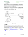
Figure 3-1 Source Diagram ---------------------------------------------------- 79
Figure 3-2 Sensor---------------------------------------------------------------- 80
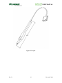
Figure 3-3 Stylus ---------------------------------------------------------------- 81
Figure 4-1 Alignment Reference Frame -------------------------------------A-1
Rev. B
v
November 2004
USER MANUAL
LIST OF TABLES
Table 2-1
Table 2-2
Table 2-3
Table 2-4
Table 2-5
Table 2-6
Table 2-7
Table 2-8
Table 2-9
Table 2-10
Table 2-11
Table 2-12
Table 2-13
Table 2-14
Table 2-15
Table 2-16
Table 2-17
Table 2-18
Table 2-19
Table 2-20
Table 2-21
Table 2-22
Table 2-23
Table 2-24
Table 2-25
Table 2-26
Table 2-27
Table 2-28
Table 2-29
Table 2-30
Table 2-31
Table 2-32
Table 2-33
Table 2-34
Table 2-35
Table 2-36
Table 2-37
Table 2-38
Table 2-39
Table 2-40
Table 2-41
Table 2-42
Table 2-43
Table 2-44
Table 2-45
Table 2-46
Table 2-47
Table 2-48
Table 3-1
Table 3-2
Table 3-3
Table 4-1
Table 4-2
Table 4-3
Table 4-4
Table 4-5
Rev. B
ASCII Response Format ---------------------------------------------------------------------20
Binary Response Format---------------------------------------------------------------------21
‘A’ ASCII Response--------------------------------------------------------------------------26
‘A’ Binary Response -------------------------------------------------------------------------26
‘B’ ASCII Response--------------------------------------------------------------------------29
‘B’ Binary Response -------------------------------------------------------------------------29
‘F’ ASCII Response --------------------------------------------------------------------------31
‘F’ Binary Response--------------------------------------------------------------------------31
‘G’ ASCII Response--------------------------------------------------------------------------32
‘G’ Binary Response -------------------------------------------------------------------------32
‘H’ ASCII Response--------------------------------------------------------------------------35
‘H’ Binary Response -------------------------------------------------------------------------35
‘L’ ASCII Response --------------------------------------------------------------------------38
‘L’ Binary Response--------------------------------------------------------------------------38
‘N’ ASCII Response--------------------------------------------------------------------------40
‘N’ Binary Response -------------------------------------------------------------------------40
Output Data Types----------------------------------------------------------------------------41
‘O’ ASCII Response--------------------------------------------------------------------------42
‘O’ Binary Response -------------------------------------------------------------------------42
‘U’ ASCII Response--------------------------------------------------------------------------43
‘U’ Binary Response -------------------------------------------------------------------------43
‘X’ ASCII Response--------------------------------------------------------------------------46
‘X’ Binary Response -------------------------------------------------------------------------47
‘Y’ ASCII Response--------------------------------------------------------------------------49
‘Y’ Binary Response -------------------------------------------------------------------------50
‘^E’ ASCII Response ------------------------------------------------------------------------52
‘^E’ Binary Response ------------------------------------------------------------------------52
ASCII Baud Rate Values --------------------------------------------------------------------53
ASCII Parity Values--------------------------------------------------------------------------53
‘^O’ ASCII Response ------------------------------------------------------------------------54
‘^O’ Binary Response------------------------------------------------------------------------54
Binary RS-232 Codes ------------------------------------------------------------------------54
‘^U[station]’ ASCII Response --------------------------------------------------------------57
‘^U0’ ASCII Response-----------------------------------------------------------------------57
‘^U’ Binary Response------------------------------------------------------------------------57
‘^X’ ASCII Response ------------------------------------------------------------------------59
‘^X’ Binary Response------------------------------------------------------------------------60
‘P’ ASCII Response --------------------------------------------------------------------------63
‘P’ Binary Response--------------------------------------------------------------------------64
‘^T’ ASCII Response ------------------------------------------------------------------------68
‘^T’ Binary Response ------------------------------------------------------------------------68
‘^V’ ASCII Response ------------------------------------------------------------------------69
‘^V’ Binary Response------------------------------------------------------------------------70
‘^V[station] ASCII Response ---------------------------------------------------------------70
‘^V[station]’ Binary Response--------------------------------------------------------------70
‘^Z’ ASCII Response Header ---------------------------------------------------------------73
‘^Z’ ASCII Response ------------------------------------------------------------------------74
‘^Z’ Binary Response ------------------------------------------------------------------------75
LED conditions -------------------------------------------------------------------------------78
RS-232 Pin Outs ------------------------------------------------------------------------------78
Switch Settings--------------------------------------------------------------------------------79
BIT Results DWORDs --------------------------------------------------------------------- C-1
Source BIT Results ------------------------------------------------------------------------- C-1
Global Sensor BIT Results ---------------------------------------------------------------- C-2
Sensor Channel BIT Results -------------------------------------------------------------- C-2
Runtime BIT Error Codes ----------------------------------------------------------------- C-3
vi
November 2004
USER MANUAL
1. Getting Started
Congratulations on buying the latest, most cost-effective 3D tracking system yet! This
section of the user manual has been provided to help get your project under way as
quickly as possible.
As with any new system, there are two ways to get started with your PATRIOT system:
you could “wing it,” which involves a great deal of assumptions based on previous
experience and/or visual inspection, and hope for the best. Alternatively, you could sit
down and read the whole manual, line-by-line, and then start. What we provide here is a
middle ground to cover the basics to get you going quickly. However, this approach does
not preclude using the manual as a precise guide, reference and final arbiter.
1.1 Set Up the PATRIOT
NOTE: This approach assumes the use of a single sensor, availability of a USB or COM
Port on a computer with either Windows 2000 or Windows XP, and that the Polhemus
PiMgr GUI is installed on the computer. See Install the Host Software on page 6 for
instructions.
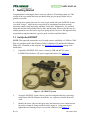
1.
Unpack the PATRIOT SEU, source, sensor(s), USB and RS-232 cables,
PATRIOT Host Software CD, power supply and cables. See Figure 1-1.
Figure 1-1 PATRIOT System
2.
Set up the PATRIOT system close to your host computer and away from large
metal objects like file cabinets, metal desks, etc., and away from the floor and
walls.
3.
Identify the source (the two-inch gray cube) and insert the source connector into
the source receptacle, being careful to firmly engage it. Using your fingers,
tighten the two retaining screws to secure the connector. See Figure 1-2.
Rev. B
1
November 2004
USER MANUAL
Figure 1-2 Source Connection
4.
For getting started, use only one sensor. Identify the sensor and insert it into either
of the sensor receptacles as shown below. Firmly engage and lock the sensor
connector into place in the same manner as the source connector in step 3. See
Figure 1-3.
Figure 1-3 Sensor Connection
5.
Rev. B
For testing purposes, it is convenient to mount both the source and the sensor on a
single block of wood (2x4 or equivalent) about 16 inches apart. Exact placement
of the source and sensor is not important for this test; just make sure the cables of
both devices are not routed tightly together and that they come off opposite
ends of the wooden block. See Figure 1-4.
2
November 2004
USER MANUAL
Figure 1-4 Sensor/Source Test Setup
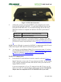
6.
Ensure the power switch is in the OFF position (logic “0”, DOWN). With the
separate power supply UNPLUGGED from the wall, connect the power input
cable to the PATRIOT. The power supply can now be plugged into a 110/220
VAC outlet. See Figure 1-5.
Figure 1-5 Power Connector
USB or RS-232 Communication
Only one I/O port (USB or RS-232) can be active at a time.
• For USB, continue with step 7.
• For RS-232, skip to step 11.
For USB Communication:
7.
Rev. B
Identify the USB cable and insert it into the receptacle as shown in Figure 1-6.
Connect the other end of the USB cable to the host computer.
3
November 2004
USER MANUAL
Figure 1-6 USB Cable Connection
8.
9.
At this point, you may turn on the PATRIOT system using the power switch
located on the back panel of the SEU. A system status indicator located on the
front panel should flash red for 5 to 10 seconds indicating self-test and set-up.
When these routines are completed, the indicator will reflect system status as
follows:
• Steady green
System operational – passed startup testing.
• Flashing red
Failed self-test and set-up.
The host should respond with a “Found New Hardware” message. Follow the
hardware wizard to install the required drivers from the PATRIOT Host Software
CD-ROM. For step-by-step instructions, refer to USB Driver Installation on page
6.
NOTE: Once the USB cable is connected to PATRIOT, it cannot return to RS-232 mode
without removing the USB connection and restarting (power OFF/ON).
10.
You may now use the Polhemus PiMgr GUI to exercise the system. If you have
not yet installed the Host Software, continue to Install the Host Software on page
6. Otherwise, continue to Use the Polhemus PiMgr GUI on page 6 and
Experiment with PATRIOT Data on page 9.
For RS-232 Communication:
11.
Locate the RS-232 cable and insert it into the receptacle as shown in Figure 1-7.
Most PC hosts have a 9 pin, male “D” type connector for COM1. If you are using
COM1, plug the remaining end of the cable into the COM1 port of the host PC,
engage, and lock as before.
If your host computer has a 25 pin “D” connector for the RS-232 port, you will
need a 9 to 25 pin “D” connector adapter with the proper genders. Note that this
adapter must not compromise the NULL MODEM sense of your cable.
Rev. B
4
November 2004
USER MANUAL
Figure 1-7 RS-232 Cable Connection
12.
You may now exercise the system. To use the Polhemus PiMgr GUI, return to
step 10. With the RS-232 connection, you may also use PATRIOT’s ASCII
interface through the Windows HyperTerminal program.
To do this, first set PATRIOT’s “CONFIG” hardware switches to all DOWN as
shown in Figure 1-7. (RS-232 switch settings are described in detail in RS-232 I/O
on page 78.)
Next, start the HyperTerminal program and create a serial connection using these
switch settings. The steps are as follows:
•
•
•
•
•
•
•
•
Navigate to HyperTerminal from the Windows Start menu. StartÖAll
ProgramsÖAccessoriesÖCommunicationsÖHyperTerminal.
In HyperTerminal, enter a session name, choose an icon, and click OK
In the “Connect using” field, select the desired COM port (COM1) and click OK.
In the “Bits per second” field, select 115200.
In the “Data bits” field, select 8 (default).
In the “Parity” field, select None (default).
In the “Stop bits” field, select 1 (default).
In the “Flow control” field, select None and click OK.
13.
You should now have a serial connection opened to PATRIOT. Turn PATRIOT
on. In 5 to 10 seconds, you will see “PATRIOT Ready!” in the HyperTerminal
screen.
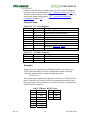
14.
Collect a single data record from PATRIOT by typing the ‘P’ – Single Data
Record Output command (see page 63) in the HyperTerminal screen. PATRIOT
will respond with a single frame of position and orientation data. The data
displayed in the HyperTerminal screen consists of a station number and six
columns of data as follows (these values represent an arbitrary placement of the
sensor and source.):
1
01
Rev. B
2
16.082
3
-0.387
4
0.713
5
5
3.051
6
1.126
7
-0.674
November 2004
USER MANUAL
15.
Continue experimenting with the position and orientation data. See Experiment
with PATRIOT Data on page 9. If the system fails to produce position and
orientation data, carefully go over the above procedure in a systematic fashion,
checking connections and switch settings especially. If you still need assistance,
refer to Customer Service on page F-1.
1.2 Install the Host Software
NOTE: PATRIOT Host Software is intended to be installed on a computer running
Windows 2000 or Windows XP only.
•
Insert the PATRIOT Host Software CD-ROM into your computer’s CD-ROM drive.
•
If the PATRIOT Host Software Installation Panel does not run automatically, then
navigate to the CD-ROM drive using Windows Explorer. Run “Setup.exe”. The Host
Software Installation Panel will appear. Click on “Install Host Software.” The
installation wizard will walk you through the installation.
•
For simplicity, it is recommended that you use the default installation settings
suggested by the installation wizard.
•
When the installation is complete, if you are planning to use your computer’s USB
port to connect to the PATRIOT System, leave the CD-ROM in the drive. It will be
needed when the initial USB connection is made.
•
If you are not planning to use the USB port, you may remove the CD-ROM from the
drive now.
1.2.1 USB Driver Installation
•
When PATRIOT is connected via USB to a Windows host for the first time, the host
will display a “Found New Hardware” message. The host will then launch the
“Found New Hardware Wizard” to locate and install the USB drivers for PATRIOT.
•
If the CD-ROM is not already in the drive, load it now.
•
When the Found New Hardware Wizard displays, select the “Install software
automatically” option and click “Next.”
•
The wizard will install the PATRIOT Loader. When it has completed, click “Finish.”
•
The same process will be launched again automatically to install the Polhemus
PATRIOT USB Driver. Repeat the same selections and the process will be complete.
1.3 Use the Polhemus PiMgr GUI
If you selected the default settings when you installed the PATRIOT Host Software on
your computer, you will find a shortcut to the PiMgr application on your Windows 2000
or XP desktop. It looks like this:
Rev. B
6
November 2004
USER MANUAL
Otherwise, navigate to the program through the windows Start menu:
StartÖAll ProgramsÖPolhemusÖPiMgr
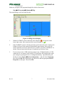
The initial PiMgr screen will look like this:
Figure 1-8 PiMgr Screen Display
1.
icon appears in the
With no PATRIOT system connected, notice that the
lower right corner. Once connected, the icon will change to
.
2.
If the PATRIOT system is already powered up and connected to the computer, the
PiMgr will discover the connection immediately upon startup. If not, you will
need to manually create the connection once you have powered up PATRIOT. To
do this, first you must select the type of connection you wish to create.
3.
If you want to create a USB connection, skip to step 4. PiMgr defaults to a USB
connection. If you want to create an RS-232 connection, first configure the serial
port settings by opening the Device Configuration dialog. Open this dialog off
the Device menu: DeviceÖDevice Configuration…, and select the Connection
tab. Select the RS-232 Connection Type on the left, and the appropriate RS-232
Properties on the right. Then Click OK.
Rev. B
7
November 2004
USER MANUAL
Figure 1-9 RS-232 Configuration Settings
4.
.
To create a connection, click the Connect button on the PiMgr toolbar:
When the connection has been established, the connection icon at the lower right
will change to
.
5.
To collect a single frame of motion data from the PATRIOT system, click the
Single button on the toolbar:
6.
You can also do this by typing ‘p’ or ‘P’ anywhere on the PiMgr window. This
will cause PiMgr to request a single data frame from the PATRIOT system. The
contents of the frame will be displayed in the text window at the top of the PiMgr
display. The airplane image(s) in the graphics portion of the screen will move to
the retrieved position and orientation:
Figure 1-10 PATRIOT Data Record Display
The text portion of the screen will display the retrieved position and orientation:
Station Number
1
Rev. B
Position in inches
X
Y
Z
0.389 34.603 0.000
8
Euler Orientation in degrees
Azimuth Elevation
Roll
-1.000
0.000
88.000
November 2004
USER MANUAL
1.4 Experiment with PATRIOT Data
1.
Take some initial samples of data using the ‘P’ – Single Data Record Output
command (see page 63). Because you have locked the sensor in one position
relative to the source (Set Up the PATRIOT, step 5), the data output will not
change regardless of the number of data samples you take.
2.
Remove the sensor, move it approximately six inches toward the source, secure it
in place, and take another single data frame. The value of the X position data will
decrease by approximately six inches. The Y and Z values will remain roughly the
same as the original data. If you left the attitude of the sensor approximately the
same as it was when you started, then the attitude data also will be approximately
the same.
3.
Again, remove the sensor and without moving its position, try twisting it in
azimuth (in the same plane as the wood support) approximately 45 degrees and
lock it down with tape. Now collect another data frame. The first four columns
will be approximately as they were in step 1, but the Azimuth data in column 5
will have changed by approximately 45 degrees.
4.
Continue to experiment with the system as described in step 3 to demonstrate that
it measures the position and orientation (six-degree-of-freedom) of the sensor
with respect to the source.
5.
For a more “hands-on” approach to communicating with PATRIOT, an RS-232
connection is available.
Rev. B
9
November 2004
USER MANUAL
1.5 Terms/Acronyms
Alignment
Obtaining congruence between the axes of the PATRIOT system
and the axes of the application. The process whereby the
PATRIOT system coordinate reference is brought into
coincidence, either physically or mathematically, with other
coordinates of the environment. Alignment in an active system is
not the same as a boresight operation, which concerns only the
sensor; in passive systems, alignment and boresight can be
identical.
Alignment Frame
The reference frame in which the position and orientation of the
sensor is measured. The default alignment frame is the source
frame.
API
Application Programming Interface. Programming library used to
develop custom host software for driving the instrument.
Sometimes used interchangeably with “SDK.”
ASCII
American national Standard Code for Information Interchange
defines a certain 8-bit code for display and control characters.
Attitude Matrix
A three-by-three matrix containing the direction cosines of the
sensor’s X axis in column one, the direction cosines of the sensor’s
Y axis in column two, and the direction cosines of the sensor’s Z
axis in column three. The order of the Euler angle rotation
sequence is azimuth, elevation, and roll.
X Direction Cosines
CA*CE
SA*CE
-SE
Y Direction Cosines
Z Direction Cosines
CA*SE*SR - SA*CR
CA*CR + SA*SE*SR
CE*SR
CA*SE*CR + SA*SR
SA*SE*CR – CA*SR
CE*CR
where:
CA = Cos (azimuth)
CE = Cos (elevation)
CR = Cos (roll)
SA = Sin (azimuth)
SE = Sin (elevation)
SR = Sin (roll)
Rev. B
10
November 2004
USER MANUAL
Azimuth
The coordinate of orientation tracking in the horizontal plane
where an increase in the angle is clockwise when viewed from
above. Azimuth is a rotation around the “Z” or vertical axis. The
term “yaw” is often substituted for azimuth, especially in the
context of flight.
Baud Rate
The signaling rate on a serial line. For example, to convey an 8-bit
byte normally requires at least two additional bit times, a start bit
and a stop bit so that synchronization is possible without a separate
clocking line. For example, such an arrangement implies for a
9600 baud rate conveyance of data at a 9600*8/10 = 7680 bit rate.
Benign Environment A tracking environment free of the need for special calibration or
compensation brought on by the unique features of a particular
installation and its environment (e.g. high light levels for optical
tracking, high sound levels for sonic tracking, high metallic
distortion for magnetic tracking). If not otherwise noted, all
measurements and statements pertaining to PATRIOT performance
shall be regarded as occurring in such a benign environment.
Binary
Mathematical system based on two digits: 0 and 1.
BIT
Built-In Test features monitoring the status and health of the
PATRIOT system, as well as flagging certain preset conditions
monitored by the PATRIOT system software. Not to be confused
with bit, a contraction of “binary digit.”
Boresight
Any procedure that rotates the sensor frame so as to precisely align
the sensor to the designated reference frame.
In a PATRIOT system context, the term usually refers to the
system software routine that, on command, performs a coordinate
rotation, which effectively aligns the sensor frame to a predefined
boresight reference orientation.
The boresight routine accomplishes the boresight orientation of the
sensor regardless of the sensor’s physical orientation at the instant
of boresight initiation. For applications that require the orientation
tracking of the body (or body member) to which the sensor is
attached, a prerequisite to initiating the boresight function is a
physical orientation of the body to be tracked to the boresight
reference orientation.
Rev. B
11
November 2004
USER MANUAL
bps
Bits per second. Not to be confused with the signaling, or baud
rate, which is always equal to or higher than the bit rate. (See baud
rate.)
Direction Cosines
The cosines of the angles between the sensor’s x, y, z axes and the
X, Y, Z axes of the measurement reference (alignment) frame.
Elevation
Coordinate of orientation tracking in the vertical plane where an
increase in the angle is upward from the horizontal. A term often
substituted for elevation, especially as it concerns flight, is “pitch.”
Factory Defaults
The values assigned to certain system variables by the factory.
Stored in non-volatile memory, they are used to reinitialize the
variables if configuration information is lost.
Firmware
Term used to describe the software programmed into PATRIOT
non-volatile memory.
Format
The interchange coding used to present data. PATRIOT outputs
either ASCII or BINARY data, but accepts only ASCII inputs from
the host.
Hemisphere
Because of the inversion symmetry of the magnetic fields
generated by the source, there are two possible mathematical
solutions for the X, Y, Z position coordinates for each set of sensor
data processed, and PATRIOT is unable to determine which
solution is the correct one without additional information. This
additional information is provided by the ‘H’ – Hemisphere of
Operation command on page 34, which defines the hemisphere in
which the sensors are operating. Therefore, only half of the total
spatial sphere surrounding the source can be utilized at any one
time for unambiguous position measurement.
The selected hemisphere is referred to as the “current hemisphere.”
It is defined by an LOS (line-of-sight) vector from the source
through a point at the zenith of the hemisphere, and is specified by
the direction cosines of the chosen LOS vector.
The orientation coordinates do not have a two-solution spherical
ambiguity and are therefore valid throughout the operating sphere
centered at the source.
Rev. B
12
November 2004
USER MANUAL
Host
Any device capable of supporting an RS-232C interface or the high
speed USB interface and capable of bi-directional data
transmission. Devices may range from a dumb terminal to a
mainframe computer.
I/O latency
The interval of time needed by the host computer to transfer data
from the PATRIOT system into the host application.
Lag
The interval of time between requesting a PATRIOT system data
point and receiving it into the host computer.
Latency
The interval of time between when measurement data were
collected and when the P&O result is formatted ready for transfer
to the host computer. In some systems, namely active PATRIOT
systems, there is a time interval between when the data is collected
and when the P&O computation can be done. Hence, this
definition is intended to correspond to the center point of data
collection time so that latency is straightforward and
understandable as stated. Other tracking systems (e.g., inertial)
may produce raw data continuously or nearly continuously.
PATRIOT latency in this case reduces to the computation time for
producing the answer ready for transfer to the host computer.
LIBERTY
A generation of flexible and expandable motion tracking
instruments after which the PATRIOT is modeled, using the same
sources and sensors. The LIBERTY 240/8 allows up to 8 sensors,
while the LIBERTY 240/16 allows up to 16 sensors.
Line of Sight (LOS) 1) The orientation angle of the source/sensor pair; 2) in active
tracking systems, the angle between the source of stimulation and
the sensor; 3) not obscured or blocked from view, such as a clear
line of sight for optical uses.
LSB
Least significant bit
LSD
Least significant digit.
MSB
Most significant bit.
Rev. B
13
November 2004
USER MANUAL
Motion Box
The volume in which motion tracking is specified to perform as
prescribed. Although this 3D volume usually is cubicle in nature,
many of the tracking technologies known as ‘active’ are dependent
on a source of stimulation (e.g., magnetic field, light source) which
actually performs equally well at a constant radius from the source
so that the “box” actually might be better described as spherical or
hemispherical.
Orientation Angles The azimuth, elevation, and roll angles that define the current
orientation of the sensor coordinate frame with respect to the
designated reference frame.
The Euler angle coordinates that are output by PATRIOT as one
measure of sensor orientation are graphically defined in Figure
1-11. Here, the x, y, z and X, Y, Z tri-axis arrays represent
independent, three-dimensional orthogonal coordinate frames. The
x, y, z triad represents the sensor frame in its current orientation
state. The X, Y, Z triad represents the reference frame against
which the relative orientation of the sensor frame is measured. By
definition, the X, Y, Z frame also represents the zero-orientation
reference state of the sensor frame.
The Euler angles, azimuth, elevation and roll, are designated ψ, θ,
and φ. These angles represent an azimuth-primary sequence of
frame rotations that define the current orientation of the sensor
with respect to its zero-orientation state. The defining rotation
sequence is an azimuth rotation followed by an elevation rotation
followed by a roll rotation.
The azimuth angle ψ is defined in the figure as a rotation of the X
and Y reference axes about the Z reference axis. The transition
axes labeled X’ and Y’ represent the orientation of the X and Y
axes after the azimuth rotation.
The elevation angle θ is defined as a rotation of the Z reference
axis and the X’ transition axis about the Y’ transition axis. The
transition axis labeled Z’ represents the orientation of the Z
reference axis after the elevation rotation. The current x-axis of the
current sensor frame represents the orientation of the X’ transition
axis after the elevation rotation.
Lastly, the roll angle φ is defined as a rotation of the Y’ and Z’
transition axes about the x-axis of the sensor frame. The y and zaxes of the current sensor frame represent the orientation of the Y’
and Z’ transition axes after the roll rotation.
Rev. B
14
November 2004
USER MANUAL
In the example of Figure 1-11, the azimuth, elevation and roll
rotations are positive, negative and positive respectively.
Legend
X, Y, Z = Alignment (Reference) Frame
x, y, z = Rotated Stylus or Sensor Coordinate Frame
Ψ
θ
φ
= Azimuth
= Elevation
= Roll
Figure 1-11 Euler Angles
Output List
A list of the data items included in a data record.
PATRIOT
A two-sensor low cost tracking instrument modeled after
LIBERTY.
P&O
Acronym for position and orientation, the six pieces of data needed
to fully describe tracking of an object in 3D space. Some tracking
devices, by virtue of their principle of operation, can produce only
position or only orientation whereas others can produce both P&O
(although the user usually can opt for only those parameters desired).
Pitch
Same as elevation.
Quaternion
A four-parameter quantity representing a vector and a scalar. The
quaternion q = q0 + i q1 + j q2 + k q3 can be used to represent the
sensor’s orientation without the need for trigonometric functions.
The attitude matrix output from PATRIOT can be equivalently
represented by the following matrix using quaternions:
X Directional Cosines
⎡ q2 + q2 - q2 - q2
⎢ 0 1 2 3
⎢
⎢ 2( q3 q0 + q1 q 2 )
⎢
⎢2( q1 q3 - q0 q 2 )
⎣
Rev. B
Y Directional Cosines
2( q1 q 2 - q0 q3 )
2
2
2
2
q0 - q1 + q 2 - q 3
2( q1 q0 + q3 q 2 )
15
Z Directional Cosines
2( q1 q3 + q0 q 2 )⎤
⎥
⎥
2( q 2 q3 - q0 q1 )⎥
⎥
2
2
2
2
q0 - q1 - q 2 + q3 ⎥⎦
November 2004
USER MANUAL
Response
The interval of time between a request to the PATRIOT system to
collect a data point and when that data is available for input from
the PATRIOT system.
Roll
Coordinate of orientation tracking about the azimuth-elevation axis
where an increase of the angle is clockwise as viewed from behind or
in the same direction as the object is facing.
SDK
Software Development Kit; software development toolset available
for LIBERTY/PATRIOT-based trackers, consisting of
programming libraries, help files, and sample code. SDK is
sometimes referred to as “API,” although API refers specifically to
the programming libraries used to interface with the instrument.
Sensor
The sensor measures the low-frequency magnetic field generated
by the source. The sensor is used to track both the position and
orientation of the object to which it is attached, relative to the
measurement reference frame.
Source
The source generates the low-frequency magnetic field measured
by the sensor. The source’s X, Y, and Z-axes are the default
measurement reference frame.
Station
The source-sensor pair. PATRIOT supports up to two sensors,
yielding a possible two stations.
Stylus
A pencil-shaped housing for the sensor with an integral switch and
used by the operator to indicate and/or select points to be digitized.
Sync
Shorthand for synchronization. For example, “sync signal.”
Units
The unit of assumed distance. PATRIOT allows measurement in
either inches or centimeters.
Update Rate
The rate at which motion-tracking data can be made available from
the PATRIOT system.
Useful Range
The maximum distance at which the resolution and noise
performance of the PATRIOT system can be realized.
Rev. B
16
November 2004
USER MANUAL
User Defaults
The values assigned to certain system variables by the user. Stored
in non-volatile memory, the system receives these variable values
at power-up.
XYZ or X, Y, Z
The Cartesian coordinates of position tracking where normally +X is
in the forward direction; +Y is in the right hand direction; and +Z is
downward.
XYZAER
The output string of data reporting the position, XYZ, and
orientation, AER – azimuth, elevation and roll – of the tracking
sensor.
Yaw
Same as azimuth.
<>
Used in text to indicate the “Enter” key.
^
Used in text to indicate the “Ctrl” key.
Rev. B
17
November 2004
USER MANUAL
2. PATRIOT System Commands
2.1 Overview
This section specifies the PATRIOT Command Interface. It defines the structure and
function of PATRIOT commands and responses.
The interface is comprised of ASCII commands and binary or ASCII response frames.
The ASCII commands are designed to work in a ‘dumb terminal’ mode, thus keeping the
communications protocol simple and easy to use. These commands are the basis of the
Polhemus APIs.
Additional information is provided in this document to give the reader some background
in the terminology and general science behind the Polhemus tracking technology.
All commands are input on the RS-232 serial port or USB port.
2.2 Command Syntax
2.2.1 Notation
The following notation is used in this manual to describe the PATRIOT command
syntax:
[]
Items shown inside square brackets are optional. To include
optional items, type only the information inside the brackets. Do
not type the brackets.
<>
Represents an ASCII carriage return or “enter” (‘^M’, 0x0d).
Whenever shown this value must be present to terminate the
command sequence.
...
An ellipsis indicates that you can repeat an item.
,
A comma represents a delimiter in a list of optional parameters.
The comma must be present for those parameters which are
omitted except for the case of trailing commas. For example:
Qs,p1,,,p4<>
is the proper command format when omitting parameters p2 and
p3. Commas following the parameter p4 are not required if
parameters p5 and p6 are omitted.
|
A vertical bar means either/or. Choose one of the separated items
and type it as part of the command. For example,
“ON|OFF” indicates that you should enter either ON or OFF, but
not both. Do not enter the vertical bar.
Rev. B
18
November 2004
USER MANUAL
^
A caret in front of a command letter indicates that the control key
should be held down while typing the command letter. Control
commands produce ASCII values between 0x00 and 0x1F.
For discussion purposes, examples assume that only one sensor is used, in the Sensor 1
position.
2.2.2 Command Format Notes
•
Commands and alphabetic parameters are NOT case sensitive.
•
Commands that use optional parameters use current system retained values for
parameters omitted from the command.
•
The term “station” refers to a source-sensor pair. For example, eight sensors paired
with the one available source are assigned station numbers one through eight (1-8).
•
Unless otherwise noted, commands do not take any punctuation immediately
following the command letter. However, if an optional first parameter is to be
omitted, a comma is necessary between the command letter and the next parameter.
•
A numeric floating point value will be accepted by the machine if any of the
following formats are used. For example, 3.0 may be specified as: 3, 3., 3.0 or
3.0E+00.
Station Wildcard
When using a command that requires a station number as the parameter, the user may
wish to apply the command to both stations of the PATRIOT system. In such situations a
‘*’ character may be used in place of the station number to apply the settings to both
stations in the PATRIOT system.
e.g. H*,0,0,1<> would change the hemisphere for every station to the positive Z
hemisphere.
e.g. H1,0,0,1<> would change the hemisphere for only station 1 to the positive Z
hemisphere.
Default Parameters
Commands that take multiple parameters can be used to change a subset of the
parameters and leave the remaining parameter values unchanged.
For example:
•
The command Gaz,el,roll<> changes the source mounting frame to (az, el, roll).
•
The command G0,180,0<> changes the source mounting frame to (0,180,0). By
omitting the el parameter from the command: G0,,180<> the source mounting frame
would then change to (0,180,180). The el setting remains unchanged.
Rev. B
19
November 2004
USER MANUAL
•
Similarly, the az parameter can be defaulted by: Gel,roll<> and the roll parameter
can be defaulted by Gaz,el<>. The trailing comma is not required when the last
parameter(s) are omitted.
2.2.3 Response Format Notes
Depending on the ‘F’ – Output Format configuration setting (see page 30), frames
received from PATRIOT in response to the commands detailed in this document will
conform to one of the following format definitions.
ASCII
ASCII response frames are described in this document using the following notation:
A............... Is an ASCII Character
B .............. Is a Blank or Space
S .............. Is the Sign byte (+,- or a space for (+))
x ............... Is a decimal digit (0-9)
<> .............Carriage Return + Line Feed (i.e. ^M^J, 0x0d 0x0a)
n() ............ Repeat contents of parentheses n times
Example:
A format 3(Sx.xxxxB), would be output as: -1.1111 2.2222 -3.3333
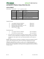
Except where noted, ASCII mode response includes a standard 5-character response
header. The default ASCII response frame format is as follows:
HEADER
Table 2-1 ASCII Response Format
Byte Index
0
1
2
3
4
5 thru n
n+1, n+2
Format
A
A
A
A
B
A
<>
Description
First Digit of Station Number
Second Digit of Station Number
Command Letter
Error Indicator
ASCII Blank character
Response Body
A P&O response frame may not contain a
Carriage Return/Line Feed as specified by
the user with the ‘O’ command
If the Station Number is not applicable to the command, the first two fields will be ASCII
zeros ‘0’.
Error codes presented in the Error Indicator field are detailed in PATRIOT Error Code
Summary on page 23. “No Error” is represented by an ASCII blank character ‘ ‘.
Binary
Binary response frames are described in this document using the following notation:
US ............unsigned short, 16 bits
SH ............signed short, 16 bits
UC ............unsigned char, 8 bits
Rev. B
20
November 2004
USER MANUAL
CH ............char, 8 bits
I ................signed integer, 32 bits
DW...........unsigned double word, 32 bits
FL.............32-bit single-precision floating-point in IEEE format consisting
of sign bit, 8-bit exponent, and 23-bit mantissa:
SXXX XXXX XMMM MMMM MMMM MMMM MMMM MMMM
[n].............Array of size n of type preceding square brackets (e.g. FL[3])
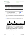
Binary response frames are composed of an 8 byte frame header followed by a variablelength frame body as follows:
HEADER
Table 2-2 Binary Response Format
Byte Index
0,1
2
3
4
5
6,7
8-n
TYPE
US
UC
UC
UC
UC
SH
Description
Frame Tag, always ‘PA’ or 0x5041 for PATRIOT HST
Station Number
Initiating command
Error Indicator
Reserved
Response size; number of bytes in the response body
Binary Response body
Error codes presented in the Error Indicator field are detailed in PATRIOT Error Code
Summary on page 23. “No Error” is represented by NULL (0x00).
Error Responses
When in binary mode, error responses are always prepended by the binary frame header,
followed by the ASCII error string. In ASCII mode, error responses have no header. See
PATRIOT Error Code Summary on page 23 for a complete listing of error responses.
Rev. B
21
November 2004
USER MANUAL
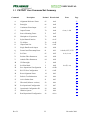
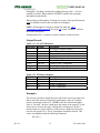
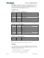
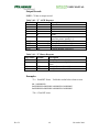
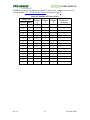
2.3 PATRIOT User Command Set Summary
Command
Description
Decimal Hexadecimal
Notes
Page
A
Alignment Reference Frame
65
0x41
25
B
Boresight
66
0x42
28
C
Continuous Print Output
67
0x43
62
F
Output Format
70
0x46
G
Source Mounting Frame
71
0x47
32
H
Hemisphere of Operation
72
0x48
34
L
Stylus Button Function
76
0x4C
37
N
Tip Offsets
78
0x4E
39
O
Output Data List
79
0x4F
41
P
Single Data Record Output
80
0x50
63
Q
FrameCount/Timestamp Reset
81
0x51
0=both;1=FC,2=TS
65
U
Set Units
85
0x55
0=in, 1=cm
43
X
Position Filter Parameters
88
0x58
45
Y
Attitude Filter Parameters
89
0x59
48
^B
UN-Boresight
2
0x02
51
^E
Set Echo Mode
5
0x05
^K
Save Operational Configuration
11
0x0B
66
^O
RS-232 Port Configuration
15
0x0F
53
^R
Reset Alignment Frame
18
0x12
55
^T
Built-in-Test Information
20
0x14
67
^U
Active Station State
21
0x15
56
^V
WhoAmI (Software versions)
22
0x16
69
^W
Set Operational Configuration
23
0x17
71
^X
Operational Configuration ID
24
0x18
59
^Y
Initialize System
25
0x19
72
^Z
Read Operational Configuration
26
0x1A
73
Rev. B
22
0=asc, 1=bin
0=off, 1=on
30
52
November 2004
USER MANUAL
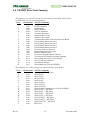
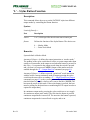
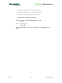
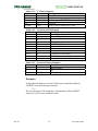
2.4 PATRIOT Error Code Summary
The following error codes may appear as binary values in binary mode frame headers.
In ASCII mode, only the text/meaning appears.
Error
Hexadecimal ASCII Text/Meaning
0
0x00
No Error
1
0x01
Invalid Command
2
0x02
Invalid Station
3
0x03
Invalid Parameter
4
0x04
Too Few Parameters
5
0x05
Too Many Parameters
6
0x06
Parameter Below Limit
7
0x07
Parameter Above Limit
8
0x08
Communication Failure with Sensor Processor Board
9
0x09
Error Initiating Sensor Processor 1
10
0x0a
Error Initiating Sensor Processor 2
11
0x0b
Error Initiating Sensor Processor 3
12
0x0c
Error Initiating Sensor Processor 4
13
0x0d
No Sensor Processors Detected
14
0x0e
Error Initiating Source Processor
15
0x0f
Memory Allocation Error
16
0x10
Excessive Command Characters Entered
17
0x11
You must exit UTH mode to send this command
18
0x12
Error reading source prom. Using Defaults
19
0x13
This is a read only command
20
0x14
Non-fatal text message
21
0x15
Error loading map (N/A for PATRIOT)
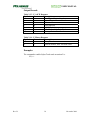
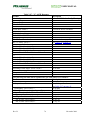
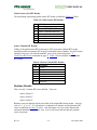
The remaining error codes may appear in ASCII and binary frame headers:
Error
‘‘
‘a’
‘b’
‘c’
‘d’
‘e’
‘f’
‘g’
‘u’
‘A’
‘B’
‘C’
‘D’
‘E’
‘F’
‘G’
‘I’
Rev. B
Hexadecimal
0x20
0x61
0x62
0x63
0x64
0x65
0x66
0x67
0x75
0x41
0x42
0x43
0x44
0x45
0x46
0x47
0x49
ASCII Text/Meaning
No Error (ASCII mode only)
Source Fail X
Source Fail Y
Source Fail XY
Source Fail Z
Source Fail XZ
Source Fail YZ
Source Fail XYZ
Position outside of mapped area (N/A for PATRIOT)
Source Fail X + BIT Errors
Source Fail Y + BIT Errors
Source Fail X + BIT Errors
Source Fail Z + BIT Errors
Source Fail XZ + BIT Errors
Source Fail YZ + BIT Errors
Source Fail XYZ + BIT Errors
BIT Errors
23
November 2004
USER MANUAL
2.5 Command Reference
2.5.1 Configuration Commands
Configuration Commands are typically issued during system setup. They affect the
overall operation of the PATRIOT system. Once a configuration has been established,
PATRIOT will operate in that configuration until power is removed, a reset is issued, or
the configuration is changed again through a command. The current configuration may be
saved and used at initialization time by commands discussed in this section.
Unless otherwise indicated, the default behavior of the configuration commands will be
as follows:
•
When no arguments (except station number, where applicable) are supplied with the
command, PATRIOT will respond with the current value of the setting in the
response frame body.
•
When arguments are supplied, the command modifies the setting, and PATRIOT
sends no response to the command. (If ‘^E’ – Set Echo Mode is enabled (see page
52), PATRIOT echoes back the command as verification that the command was
received and executed.)
•
Station-specific commands have an option to apply the setting to all stations. Refer to
Station Wildcard on page 19.
Rev. B
24
November 2004
USER MANUAL
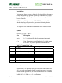
‘A’ – Alignment Reference Frame
Description:
The alignment command does two things. It defines a reference frame to
which all position and orientation output data is referred. In addition, it
creates a new origin point where the X, Y, Z measurements would equal
(0,0,0) if the sensor were placed there. An example of where this
command would be useful is a sloped test surface that the user wanted
referenced to the surface. This would obtain congruence between the
PATRIOT source and the source frame axes of the sloped surface.
Syntax:
Astation[ ,[Ox],[Oy],[Oz],[Xx],[Xy],[Xz],[Yx],[Yy],[Yz] ]<>
The Alignment Reference Frame Syntax has these parts:
Part
Description
station
1 or 2, which specifies the relevant source/sensor pair
Ox,Oy,Oz
the Cartesian coordinates of the origin of the new reference
frame
Xx,Xy,Xz
the coordinates of the point defining the positive direction
of the X-axis of the new reference frame
Yx,Yy,Yz
the coordinates of a third point that is in the positive Y
direction from the X-axis
Remarks:
The source reference frame is the default alignment reference frame.
(0,0,0,1,0,0,0,1,0) in inches.
Rev. B
25
November 2004
USER MANUAL
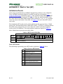
Output Record:
Table 2-3 ‘A’ ASCII Response
Byte Index Format
Description
0
A
First Digit of Station Number
1
A
Second Digit of Station Number
2
A
‘A’
3
A
Error Indicator
4
B
ASCII Blank character
5-25
3(Sxxx.xx)
Origin Coordinates
26-27
AA
Carriage Return/Line Feed
28-48
3(Sxxx.xx)
Positive X-Axis Coordinates
49-50
AA
Carriage Return/Line Feed
51-71
3(Sxxx.xx)
Positive Y-Axis Coordinates
72-73
AA
Carriage Return/Line Feed
Table 2-4 ‘A’ Binary Response
Byte Index Format
Description
0-7
Binary Header
8
FL
Ox
12
FL
Oy
16
FL
Oz
20
FL
Xx
24
FL
Xy
28
FL
Xz
32
FL
Yx
36
FL
Yy
40
FL
Yz
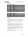
Examples:
To perform an alignment on station 1, follow the steps listed below:
Standard Alignment Procedure
Rev. B
1.
Send ^R1<>
2.
Place the sensor at the proposed origin location
3.
Press P and write down the X, Y, Z measurements (these will be
Ox, Oy, Oz)
4.
Move the sensor along the proposed X axis from the origin defined
in step 2 and place it about 24 inches in front of this origin
26
November 2004
USER MANUAL
Rev. B
5.
Press P and write down the X, Y, Z measurements (these will be
Xx, Xy, Xz)
6.
Move the sensor along the proposed Y-axis from the origin defined
in step 2 and place it about 24 inches from the source
7.
Press P and write down the X, Y, Z measurements (These will be
Yx, Yy, Yz)
8.
Using all of the data that has been written down in steps 1-7, send
the command A1,Ox,Oy,Oz,Xx,Xy,Xz,Yx,Yy,Yz<>
27
November 2004
USER MANUAL
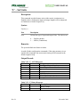
‘B’ – Boresight
Description:
This command causes the sensor to be electronically aligned in orientation
and optionally, position, with the user system coordinates and establishes
the boresight reference angles for the station. Azimuth, elevation and roll
outputs will equal the boresight reference values at the current orientation.
If the “Reset Origin” switch is set, X, Y and Z outputs will equal 0,0,0 at
the boresight location. PATRIOT then produces outputs relative to this
(these) reference(s). Any sensor orientation can be designated as the zero
orientation point.
If all the optional parameters are omitted, the system returns the boresight
reference angles for the specified station.
A station may be unboresighted by issuing a ^B command. See the section
describing the ‘^B’ – Un-Boresight Command on page 51.
Syntax:
Bstation[ ,Azref,Elref,Rlref,ResetOrigin ]<>
Part
Description
station
1 or 2, which specifies the relevant source/sensor pair
Azref
The azimuth reference angle
Elref
The elevation reference angle
Rlref
The roll reference angle
ResetOrigin
A switch to enable/disable setting the X, Y and Z origin
values to 0,0,0 upon boresight. 0 = disable the origin reset.
1 = reset origin upon boresight. Default is 0.
Remarks:
The system default boresight reference values are: 0, 0, 0
Rev. B
28
November 2004
USER MANUAL
Output Record:
Table 2-5 ‘B’ ASCII Response
Byte Index Format
Description
0
A
First Digit of Station Number
1
A
Second Digit of Station Number
2
A
‘B’
3
A
Error Indicator
4
B
ASCII Blank character
5-12
Sxxx.xxB
Azimuth Reference
13-20
Sxxx.xxB
Elevation Reference
21-28
Sxxx.xxB
Roll Reference
29-30
AA
Carriage Return/Line Feed
Table 2-6 ‘B’ Binary Response
Byte Index Format
Description
0-7
Binary Header
8
FL
Azimuth Reference
12
FL
Elevation Reference
16
FL
Roll Reference
Examples:
The sensor may be mounted on a person’s head to measure where it is
pointing. When the user’s head is looking at a given object, the user may
want the system angular outputs to be zero. The user can designate this
sensor orientation as the zero orientation by sending the boresight
command:
B1,0,0,0,0<>
This results in azimuth, elevation, and roll outputs of zero at this
orientation. As the user’s head moves away from the boresight point, the
orientation angles are still measured relative to the source, with the zero
points shifted to the point where the boresight occurred.
The user may wish to set the boresight reference values to an orientation
that corresponds with the application. For example, if the application
required an output of 0, -15, 0 following a boresight, reference angles
should be included with the B command:
B1,0,-15,0,0<>
The boresight command will now cause the azimuth, elevation, and roll
data output to be 0, -15, 0 respectively.
Rev. B
29
November 2004
USER MANUAL
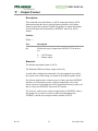
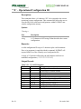
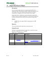
‘F’ – Output Format
Description:
This command selects the Binary or ASCII output data format. ASCII
format means that the data is generally human readable, while binary
format is generally computer readable. Regardless of output data format
selected, all input data (commands) to PATRIOT must be in ASCII
format.
Syntax:
F[fmt] <>
Part
Description
fmt
Defines the type of output from PATRIOT. The choices
are:
0 …. ASCII output
1 …. Binary output
Remarks:
The default output data format is ASCII.
The Polhemus SDK uses binary output exclusively.
As with other configuration commands, if no fmt argument is provided,
the current value of the setting is returned in the default response frame.
If a software application is written to receive binary data from PATRIOT
and there is a requirement to take it off line temporarily to do visual
checks, the user would enable the ASCII output data format in order to be
able to easily read PATRIOT data on the PC monitor.
The user may wish to write a software application for PATRIOT where a
fast update rate is crucial. In order to reduce data throughput size,
PATRIOT could be set to output in binary instead of ASCII.
Rev. B
30
November 2004
USER MANUAL
Output Record:
Table 2-7 ‘F’ ASCII Response
Byte Index Format
Description
0
A
First Digit of Station Number
1
A
Second Digit of Station Number
2
A
‘F’
3
A
Error Indicator
4
B
ASCII Blank character
5
A
‘0’
6-7
AA
Carriage Return/Line Feed
Table 2-8 ‘F’ Binary Response
Byte Index Format
Description
0-7
Binary Header
8
I
0x00000001
Examples:
The command to enable binary output mode for the system is:
F1<>
Rev. B
31
November 2004
USER MANUAL
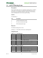
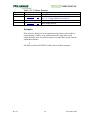
‘G’ – Source Mounting Frame
Description:
This command allows the user to modify the mounting frame coordinates
of the source. It is basically a non-physical rotation of the source and
becomes the new orientation reference for each sensor’s measurements.
Source mounting frame is not a sensor-specific setting.
Syntax:
G[ [A],[E],[R] ]<>
Part
Description
A
Azimuth mounting frame angle
E
Elevation mounting frame angle
R
Roll mounting frame angle
Remarks:
The default mounting frame is 0,0,0.
Issuing a G<> will read the current source mounting frame.
Output Record:
Table 2-9 ‘G’ ASCII Response
Byte Index Format
Description
0
A
First Digit of Station Number (n/a)
‘0’
1
A
Second Digit of Station Number (n/a) ‘0’
2
A
‘G’
3
A
Error Indicator
4
B
ASCII Blank character
5-13
Sxxx.xxxB
Azimuth Mounting Frame Angle
14-22
Sxxx.xxxB
Elevation Mounting Frame Angle
23-31
Sxxx.xxxB
Roll Mounting Frame Angle
32-33
AA
Carriage Return/Line Feed
Table 2-10 ‘G’ Binary Response
Byte Index Format
Description
0-7
Binary Header
8
FL
Azimuth Mounting Frame Angle
12
FL
Elevation Mounting Frame Angle
16
FL
Roll Mounting Frame Angle
Rev. B
32
November 2004
USER MANUAL
Examples:
If there was a requirement to mount the source upside down (more
mechanically feasible), then the following command should be used:
G0,0,180<>
The orientation measurements for all stations will now look as if the
source had not been mounted upside down.
Rev. B
33
November 2004
USER MANUAL
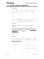
‘H’ – Hemisphere of Operation
Description:
This command allows the user to set or change the “hemisphere of
operation” vector.
Since the sensor(s) can only operate in one hemisphere at a time relative to
the source, it is necessary to tell PATRIOT which side of the source they
will be on, for each station.
PATRIOT also provides hemisphere tracking, a feature whereby
PATRIOT can continuously modify its operating hemisphere, given that it
is started in a known, valid hemisphere.
Because of the symmetry of the magnetic fields generated by the source,
there are two mathematical solutions to each set of sensor data processed.
Therefore, only half of the total spatial sphere surrounding the source is
practically used at any one time without experiencing an ambiguity
(usually sign flips) in the X, Y, Z measurements. This half sphere is
referred to as the current hemisphere. The chosen hemisphere is defined
by an LOS vector from the source through a point at the zenith of the
hemisphere, and is specified by the LOS direction cosines.
Syntax:
Hstation[ ,[p1],[p2],[p3] ]<>
Part
Description
station
1 or 2, which specifies the relevant source/sensor pair
p1
The initial x-component of a vector pointing in the
direction of the operational hemisphere’s zenith.
p2
The initial y-component of a vector pointing in the
direction of the operational hemisphere’s zenith.
p3
The initial z-component of a vector pointing in the
direction of the operational hemisphere’s zenith.
Remarks:
The arguments p1-p3 above are the vector components of the operational
hemisphere’s zenith. The default hemisphere values are: 1,0,0 which is
positive X or “forward” hemisphere.
Rev. B
34
November 2004
USER MANUAL
Hemisphere Tracking is enabled by sending Hstation,0,0,0<>. It is not
enabled by default. When enabled, PATRIOT modifies the operating
hemisphere automatically.
When turning on Hemisphere Tracking, the sensor of the specified station
must be initially located in the currently set hemisphere.
NOTE: If Hemisphere Tracking is turned ON when the ‘^X’ –
Operational Configuration ID (see page 59) is sent, PATRIOT will save
the default hemisphere.
Issuing an Hstation<> returns a record of structure as shown below.
Output Record:
Table 2-11 ‘H’ ASCII Response
Byte Index Format
Description
0
A
First Digit of Station Number
1
A
Second Digit of Station Number
2
A
‘H’
3
A
Error Indicator
4
B
ASCII Blank character
5-11
Sxx.xxx
Current Vector X component
12-18
Sxx.xxx
Current Vector Y component
19-25
Sxx.xxx
Current Vector Z component
26-27
AA
Carriage Return/Line Feed
Table 2-12 ‘H’ Binary Response
Byte Index Format
Description
0-7
Binary Header
8
FL
Vector X component
12
FL
Vector Y component
16
FL
Vector Z component
Examples:
The user may decide to mount the source above the test area in order to be
able to move the sensor to the positive and negative sides of X and the
positive and negative sides of Y. (NOTE: since the default hemisphere
value is “forward”, the user cannot move the sensor to the negative X side
of the source, because the signs will flip and it will appear as if the X
measurement never goes negative.) If the source is positioned above the
test area, the positive Z or “lower” hemisphere should be selected. This
can be accomplished with the following command:
H1,0,0,1<>
Rev. B
35
November 2004
USER MANUAL
Station 1 of PATRIOT will now be set for the positive Z or “lower”
hemisphere.
Although the hemisphere vector is not limited to 1s and 0s, the following
table of hemisphere commands may be useful:
Forward Hemisphere (+X)
Back Hemisphere (-X)
Right Hemisphere (+Y)
Left Hemisphere (-Y)
Lower Hemisphere (+Z)
Upper Hemisphere (-Z)
Rev. B
36
H1,1,0,0<>
H1,-1,0,0<>
H1,0,1,0<>
H1,0,-1,0<>
H1,0,0,1<>
H1,0,0,-1<>
November 2004
USER MANUAL
‘L’ – Stylus Button Function
Description:
This command allows the user to put the PATRIOT stylus into different
output modes by controlling the button function.
Syntax:
Lstation[,fbutton]<>
Part
Description
station
1 or 2, which specifies the relevant source/sensor pair
fbutton
Defines the function of the Stylus Button. The choices are:
0 …. Marker Mode
1 …. Point/Track Mode
Remarks:
System default is Marker Mode.
An entry of fbutton = 0 defines the output interaction as “marker mode.”
The pushing of the stylus switch has no effect on system output other than
setting an event marker in the output record when the button is pressed. In
this case, a 1 is reported in the output record when the switch is pressed
and a 0 when it is not pressed. NOTE: Output of this marker must be
enabled through the ‘O’ – Output Data List command (see page 41).
An entry of fbutton = 1 defines a pseudo “point/track” mode interaction
with the switch. In non-continuous mode of output, pressing the stylus
switch has the same effect as sending a ‘P’ – Single Data Record Output
command (see page 63) to the system (point mode). In point mode, every
time the button is pressed, a data record is sent to the host. [NOTE: The
host must be aware of this mode. If the stylus button is pressed, the host
must be polling for the data frame or monitoring RS232 output in order to
capture the output data.]
In continuous output mode, pressing the stylus switch serves as a toggle
for continuous output (track mode). The first time the button is pressed,
continuous output mode is turned off. The next time the button is pressed,
continuous output mode is turned back on again, and so on.
Rev. B
37
November 2004
USER MANUAL
Output Record:
Table 2-13 ‘L’ ASCII Response
Byte Index Format
Description
0
A
First Digit of Station Number
1
A
Second Digit of Station Number
2
A
‘L’
3
A
Error Indicator
4
B
ASCII Blank character
5
A
0 for Marker, 1 for Point/Track
6-7
AA
Carriage Return/Line Feed
Table 2-14 ‘L’ Binary Response
Byte Index Format
Description
0-7
Binary Header
8
I
0x00 for Marker, 0x01 for Point/Track
Examples:
The command to enable Stylus Track mode on station 2 is:
L2,1<>
Rev. B
38
November 2004
USER MANUAL
‘N’ – Tip Offsets
Description:
This command allows the user to override the factory defaults for the
stylus tip offsets. Although changing the tip offsets is not recommended,
the ability to do so is available.
Each stylus has been factory calibrated with custom tip offsets. This is the
offset of the sensor from the tip of the stylus. The tip offsets allow the tip
to act as the measurement reference instead of the sensor coil inside the
handle.
Tip Offset settings are not saved in the PATRIOT configuration. They
must be re-applied each time PATRIOT is restarted.
Syntax:
Nstation[ ,[Xoff],[Yoff],[Zoff] ]<>
Part
Description
station
1 or 2, which specifies the relevant source/sensor pair
Xoff
X direction Tip offset.
Yoff
Y direction Tip offset
Zoff
Z direction Tip offset
Remarks:
Factory default tip offsets are read from the PROM inside the stylus
connector on power-up. As a result, the ‘N’ command can only override
the factory defaults during the current operational session.
Rev. B
39
November 2004
USER MANUAL
Output Record:
Table 2-15 ‘N’ ASCII Response
Byte Index Format
Description
0
A
First Digit of Station Number
1
A
Second Digit of Station Number
2
A
‘N’
3
A
Error Indicator
4
B
ASCII Blank character
5-11
Sx.xxxB
X offset
12-18
Sx.xxxB
Y offset
19-25
Sx.xxxB
Z offset
26-27
AA
Carriage Return/Line Feed
Table 2-16 ‘N’ Binary Response
Byte Index Format
Description
0-7
Binary Header
8
FL
X offset
12
FL
Y offset
16
FL
Z offset
Examples:
If the user created a special stylus tip attachment that extended exactly one
inch from the end of the stylus, an adjustment to the tip offsets would have
to be made. To do so, the following steps should be taken.
1. Verify that PATRIOT is measuring units in “inches” by sending the
‘U’ – Set Units command (see page 43).
Read the factory tip offsets from the PROM in the connector by sending
the command N1<>. (A typical factory tip offset might be 2.523, 0.004,
0.03.)
2. To add one inch in X to the factory calibration, type
N1,3.523,0.004,0.03<>
To verify that the tip offset was entered correctly, type N1<> to read it
back.
Rev. B
40
November 2004
USER MANUAL
‘O’ – Output Data List
Description:
This command allows the user to define the list of variables to be output to
the host computer for the specified station. Any combination of up to 20
items that produces a P&O response frame of less than or equal to 1000
bytes is permissible.
NOTE: Due to the high output rate of PATRIOT, caution should be used
when defining large output records to prevent overwhelming the host
communications’ channel.
The output list refers to the subset of data items to be included in a data
record.
Syntax:
O[station] ,[p1],[p2],...,[pn]<>
Part
Description
station
1 or 2, which specifies the relevant source/sensor pair
p1-pn
Up to 20 parameters that define the list of variables output
to the host. The possible parameters are listed below:
Table 2-17 Output Data Types
Parameter
Value
0
1
2
3
4
5
6
7
8
9
10
Description
ASCII space character
ASCII carriage return, linefeed
X, Y, Z Cartesian coordinates of position
X, Y, Z Cartesian coords, extended precision
Az, El, Rl Euler orientation angles
Az, El, Rl Euler angles, extended precision
Direction Cosine Matrix
Orientation Quaternion
Timestamp
Frame Count
Stylus Flag (‘0’ or ‘1’)
ASCII Output Data
Format
A1
A2
3(Sxxx.xxxB)
3(Sx.xxxxxxESxxxB)
3(Sxxx.xxxB)
3(Sx.xxxxxxESxxxB)
3(3(Sx.xxxxxB)CRLF)
4(Sx.xxxxxB)
A1 ~ A10
A1 ~ A10
A1
Binary Output
Data Format
A1
A2
FL
FL
FL
FL
FL[3]
FL[3]
DWORD
DWORD
I
Remarks:
If the wildcard (*) is specified instead of a station, all station output lists
will be set to the programmed value. If output list parameters (p1-pn) are
omitted from the argument list, the current defined output list is returned.
Default is 0*,2,4,1: P&O <cr><lf> for all stations.
Rev. B
41
November 2004
USER MANUAL
Output Record:
Table 2-18 ‘O’ ASCII Response
Byte Index Format
Description
0
A
First Digit of Station Number
1
A
Second Digit of Station Number
2
A
‘O’
3
A
Error Indicator
4
B
ASCII Blank character
5
X
Data Item #1
6
B
7- .
xB..
Remaining data items separated by blanks
Table 2-19 ‘O’ Binary Response
Byte Index Format
Description
0-7
Binary Header
8
I
Data Item 1
12
I
Data Item 2
16
I
Data Item 3
...
84
I
Data Item #20
NOTE: In the binary output format, the list of valid data items will be
terminated with a -1 (0xFFFFFFFF).
Examples:
The user may decide to use X, Y, Z direction cosines instead of the default
output format. In order to do so, the following command should be sent:
O1,5,6,7,1<>
The output data for Station 1 will now be displayed as X, Y, Z direction
cosines, plus carriage return/line feed.
O*,2<>
The output for all stations will be position only.
Rev. B
42
November 2004
USER MANUAL
‘U’ – Set Units
Description:
This command sets the distance unit to either metric (centimeters) or
English (inches). Subsequent input and output lengths will be interpreted
as centimeters or inches respectively.
Syntax:
U[units] <>
Part
Description
units
Defines the type of input and output Units. The choices are:
0 …. English (Inches)
1 …. Metric (Centimeters)
Remarks:
The system default unit format is inches.
As with all other configuration commands, if the units parameter is not
stated in this command, the current units setting will be returned in the
default response body.
Output Record:
Table 2-20 ‘U’ ASCII Response
Byte Index Format
Description
0
A
First Digit of Station Number
1
A
Second Digit of Station Number
2
A
‘U’
3
A
Error Indicator
4
B
ASCII Blank character
5
A
0 for inches, 1 centimeters
6-7
AA
Carriage Return/Line Feed
Table 2-21 ‘U’ Binary Response
Byte Index Format
Description
0-7
Binary Header
8
I
0x00 for inches, 0x01 for centimeters
Rev. B
43
November 2004
USER MANUAL
Examples:
Assuming the system units had already been changed to centimeters the
following command could be sent to change back to inches:
U0<>
The system will now output data in inches and interpret input data in
inches.
If the operator wanted the system to output its measurements in
centimeters, the following command should be sent:
U1<>
The system will now output data in centimeters.
Rev. B
44
November 2004
USER MANUAL
‘X’ – Position Filter Parameters
Description:
This command establishes the sensitivity, boundary, and transition control
parameters for the adaptive filter that operates on the position outputs of
the PATRIOT system. The user can adjust the parameters of this
command to fine-tune the overall dynamic response of PATRIOT.
The filter is a single-pole low-pass type with an adaptive pole location
(i.e., a floating filter “parameter/variable”). The pole location is
constrained within the boundary values FLow and FHigh but is
continuously self-adaptive between these limits as a function of the
sensitivity parameter F and the sensed (ambient noise plus rotational rate)
input conditions. For input “rate” conditions that fall within the adaptive
range, the adaptive feature varies the pole location between the FLow and
FHigh limits so as to maximize the output resolution for static inputs
while minimizing the output lag for dynamic inputs. Whenever the input
conditions cause the filter to make a transition to a narrower bandwidth
(i.e., increased filtering), the transition rate of the pole location is
constrained to a maximum allowable rate by the parameter FACTOR. If all
of the optional parameters are omitted the current value of each parameter
is returned to the user as an output record of type “X”.
Syntax:
X[ [F],[FLow],[FHigh],[Factor] ]<>
Part
F
Description
a scalar value that establishes the sensitivity of the filter to
dynamic input conditions by specifying the proportion of new
input data to recent average data that is to be used in updating
the floating filter parameter/variable.
Allowable range of values: 0 < F < 1
FLow
a scalar value that specifies the maximum allowable filtering to
be applied to the outputs during periods of relatively static
input conditions. Setting this value to 1.0 disables the filter
completely.
Allowable range of values: 0 < FLow < FHigh or 1.0 to
disable filter
Rev. B
45
November 2004
USER MANUAL
FHigh
a scalar value that specifies the minimum allowable filtering to
be applied to the outputs during periods of highly dynamic
input conditions.
Allowable range of values: FLow < FHigh < 1
FACTOR a scalar value that specifies the maximum allowable transition
rate from minimum filtering (for highly dynamic input
conditions) to maximum filtering (for relatively static input
conditions) by proportionately limiting the decay to the low
filter limit whenever the input conditions effect a transition to a
narrower bandwidth.
Allowable range of values: 0 < FACTOR < 1
When the form of the command is X,0,1,0,0<> the position filter is
disabled.
Remarks:
The default mode for all filter parameters is shown below. Although these
parameters are a function of the user’s particular environment, the
following settings may be used as a starting point for determining
optimum filtering in your particular environment.
F
Set to 0.2
FLow
Set to 0.2
FHigh
Set to 0.8
FACTOR Set to 0.95
Output Record:
Table 2-22 ‘X’ ASCII Response
Byte Index Format
Description
0
A
First Digit of Station Number (n/a)
1
A
Second Digit of Station Number (n/a)
2
A
‘X’
3
A
Error Indicator
4
B
ASCII Blank character
5-11
Sx.xxxB
Filter Sensitivity
12-18
Sx.xxxB
Filter Low Value
19-25
Sx.xxxB
Filter High Value
26-32
Sx.xxxB
Transition Rate Maximum Value
33-34
AA
Carriage Return/Line Feed
Rev. B
46
November 2004
USER MANUAL
Table 2-23 ‘X’ Binary Response
Byte Index Format
Description
0-7
Binary Header
8
FL
Filter Sensitivity
12
FL
Filter High Value
16
FL
Filter Low Value
20
FL
Transition Rate Maximum Value
Examples:
To select the above filtering, send the following command to the system:
X .2,.2,.8,.95<>
All active stations will now have filtering applied to the position
measurements.
To turn off position filters:
X0,1,0,0<>
Rev. B
47
November 2004
USER MANUAL
‘Y’ – Attitude Filter Parameters
Description:
This command establishes the sensitivity, boundary, and transition control
parameters for the adaptive filter that operates on the attitude outputs of
the PATRIOT system. The user can adjust the parameters of this
command to fine-tune the overall dynamic response of PATRIOT.
The filter is a single-pole low-pass type with an adaptive pole location
(i.e., a floating filter “parameter/variable”). The pole location is
constrained within the boundary values FLow and FHigh but is
continuously self-adaptive between these limits as a function of the
sensitivity parameter F and the sensed (ambient noise plus rotational rate)
input conditions. For input “rate” conditions that fall within the adaptive
range, the adaptive feature varies the pole location between the FLow and
FHigh limits so as to maximize the output resolution for static inputs
while minimizing the output lag for dynamic inputs. Whenever the input
conditions cause the filter to make a transition to a narrower bandwidth
(i.e., increased filtering), the transition rate of the pole location is
constrained to a maximum allowable rate by the parameter FACTOR. If all
of the optional parameters are omitted, the current value of each parameter
is returned to the user as an output record of type “Y”.
Syntax:
Y[ [F],[FLow],[FHigh],[Factor] ]<>
Part
F
Description
a scalar value that establishes the sensitivity of the filter to
dynamic input conditions by specifying the proportion of new
input data to recent average data that is to be used in updating
the floating filter parameter/variable.
Allowable range of values: 0 < F < 1
FLow
a scalar value that specifies the maximum allowable filtering to
be applied to the outputs during periods of relatively static
input conditions. Setting this value to 1.0 disables the filter
completely.
Allowable range of values: 0 < FLow < FHigh or 1.0 to
disable filter
Rev. B
48
November 2004
USER MANUAL
FHigh
a scalar value that specifies the minimum allowable filtering to
be applied to the outputs during periods of highly dynamic
input conditions.
Allowable range of values: FLow < FHigh < 1
FACTOR a scalar value that specifies the maximum allowable transition
rate from minimum filtering (for highly dynamic input
conditions) to maximum filtering (for relatively static input
conditions) by proportionately limiting the decay to the low
filter limit whenever the input conditions effect a transition to a
narrower bandwidth.
Allowable range of values: 0 < FACTOR < 1
When the form of the command is Y0,1,0,0<> the attitude filter is
disabled. This is the system default configuration.
Remarks:
The default mode for all filter parameters is shown below. Although these
parameters are a function of the user’s particular environment, the
following settings may be used as a starting point for determining
optimum filtering in your particular environment.
F
Set to 0.2
FLow
Set to 0.2
FHigh
Set to 0.8
FACTOR
Set to 0.95
Output Record:
Table 2-24 ‘Y’ ASCII Response
Byte Index Format
Description
0
A
First Digit of Station Number (n/a)
1
A
Second Digit of Station Number (n/a)
2
A
‘Y’
3
A
Error Indicator
4
B
ASCII Blank character
5-11
Sx.xxxB
Filter Sensitivity
12-18
Sx.xxxB
Filter Low Value
19-25
Sx.xxxB
Filter High Value
26-32
Sx.xxxB
Transition Rate Maximum Value
33-34
AA
Carriage Return/Line Feed
Rev. B
49
November 2004
USER MANUAL
Table 2-25 ‘Y’ Binary Response
Byte Index Format
Description
0-7
Binary Header
8
FL
Filter Sensitivity Value
12
FL
Filter Low Value
16
FL
Filter High Value
20
FL
Transition Rate Maximum Value
Examples:
To select the above filtering, send the following command to the system:
Y.2,.2,.8,.95<>
All active stations will now have filtering applied to the attitude
measurements.
To turn off attitude filters:
Y0,1,0,0<>
Rev. B
50
November 2004
USER MANUAL
‘^B’ – Un-Boresight
Description:
This command causes the sensor boresight rotation matrix to be reset to
the identity matrix for the specified station. If the origin of the station was
previously reset using the ‘B’ – Boresight command (see page 28), the
origin will revert back to the source origin.
Syntax:
^Bstation<>
Part
Description
station
1 or 2, which specifies the relevant source/sensor pair
Remarks:
None.
Output Record:
None.
Examples:
^B1<> Resets Station 1
Rev. B
51
November 2004
USER MANUAL
‘^E’ – Set Echo Mode
Description:
This command enables and disables the communications “echo” mode. In
echo mode, Patriot responds to configuration-modifying commands by
“echoing” back the command that was received. (Recall that without echo
mode, configuration-modifying commands generate no response message
from the tracker. See Configuration Commands on page 24.) This allows
feedback to the user when modifying configuration settings. In binary
mode, the echo is prefixed by the standard 8-byte binary header.
Syntax:
^E[echo]<>
Part
Description
echo
Defines the echo mode. The choices are:
0 …. No echo mode
1 …. Echo mode
Output Record:
Table 2-26 ‘^E’ ASCII Response
Byte Index Format
Description
0
A
First Digit of Station Number
1
A
Second Digit of Station Number
2
A
‘e’
3
A
Error Indicator
4
B
ASCII Blank character
5
A
1 = on, 0 = off
6-7
AA
Carriage Return/Line Feed
Table 2-27 ‘^E’ Binary Response
Byte Index Format
Description
0-7
Binary Header
8
I
1 = on, 0 = off
Remarks:
The system default for echo mode is “off.”
Examples:
^E1<>
^E0<>
Rev. B
52
November 2004
USER MANUAL
‘^O’ – RS-232 Port Configuration
Description:
This command sets the RS-232 port configuration. The system output port
settings include RS-232 BAUD rate and parity only.
Syntax:
^O [rate],[parity]<>
Part
Description
rate
100 bits per second. Valid arguments include:
Table 2-28 ASCII Baud Rate Values
Rate Baud Rate
“24”
2,400
“48”
4,800
“96”
9,600
“192”
19,200
“384”
38,400
“576”
57,600
“1152”
115,200
parity
Table 2-29 ASCII Parity Values
Parity
“0”
“1”
“2”
Meaning
None
Odd
Even
Remarks:
See RS-232 I/O on page 78 for reference on the use of RS-232 for
communicating with PATRIOT.
By default, the baud rate and parity RS-232 parameters are determined by
the state of the RS-232 CONFIG switches (located on the back panel of
PATRIOT) upon PATRIOT startup or initialization. See Hardware
Switches on page 78 for switch values.
In addition:
Rev. B
The number of data bits is always eight (8).
The number of stop bits is always one (1).
Hardware Handshake is always disabled.
53
November 2004
USER MANUAL
Changes to the RS-232 port settings using ^O will be ignored during the
next power up or system initialize (‘^Y’ – Initialize System, page 72) in
deference to the hardware switch settings, even if the new port settings are
saved as the startup configuration (‘^W’ – Set Default Operational
Configuration on page 71).
Output Record:
Table 2-30 ‘^O’ ASCII Response
Byte Index Format
Description
0
A
First Digit of Station Number
1
A
Second Digit of Station Number
2
A
‘o’
3
A
Error Indicator
4
B
ASCII Blank character
5-10
A
Baud Rate (See Table 2-28 above.)
11
B
Blank
12
A
Parity (See Table 2-29 above.)
13-14
A
Carriage Return/Line Feed
Table 2-31 ‘^O’ Binary Response
Byte Index Format
Description
0-7
Binary Header
8
I
Baud Rate (See Table 2-32 below.)
12
I
Parity (See Table 2-32 below.)
Examples:
Suppose there is a requirement to change the baud rate (in software) to
19,200 baud after startup. It can be accomplished with the following
command, without turning off and restarting the system.
^O192,1,8,0<>
The system serial communication parameters will now be 19200-baud, no
parity, 8 data bits, and 1 stop bit. The host communication software may
have to be reset to the new baud rate (19,200) in order for communication
with PATRIOT to continue.
Table 2-32 Binary RS-232 Codes
Code Baud Rate
Code Parity
1
2400
0
None
2
4800
1
Odd
3
9600
2
Even
4
19200
5
38400
6
57600
7
115200
Rev. B
54
November 2004
USER MANUAL
‘^R’ – Reset Alignment Frame
Description:
This command resets the alignment reference frame for the specified
station to the station reference frame. It provides an easy way to re-align
the reference frame to the factory default values. The command parameter
is defined as:
Syntax:
^Rstation<>
Part
Description
station
1 or 2, which specifies the relevant source/sensor pair
Remarks:
None.
Output Record:
None.
Examples:
To reset the alignment reference frame for station 2 execute the following:
^R2<>
Rev. B
55
November 2004
USER MANUAL
‘^U’ – Active Station State
Description:
The purpose of this command is to allow the host to turn a station “on” or
“off” in software.
A station is defined as a source/sensor port pair. The two sensors paired
with the one source are assigned station numbers one and two (1,2).
Although stations are enabled simply by plugging the sensors into the
ports on PATRIOT, the stations can then be disabled (or enabled again) by
using a software command. When a station exists and is enabled, data
records for that sensor will be transmitted from that station. If the station is
disabled, no data records from that station will be transmitted.
Syntax:
^U[station][,state ]<>
or
^U0[,bitmap]<>
Part
Description
station
1 or 2, which specifies the relevant source/sensor pair
0: causes active station bitmap to be retrieved or set.
state
0 … Off
1 … On
n/a if station = 0
bitmap
8-bit bitmap reflecting state of each sensor, represented as a
hexadecimal number
Remarks:
If a station is supplied without a state, then the current states of all
stations are returned. See output record below. The default condition
depends on the number of sensors that are currently connected to
PATRIOT. The default condition of a station that has a sensor connected
to it is a “1” or station “on”. The default condition of a station that does
not have a sensor connected to it is a “0” or station “off.”
If zero ‘0’ is supplied as the station number, this command will take a
hexadecimal bitmap to identify ALL the enabled stations:
E.g.: ^U0,03<> enables all sensors.
NOTE: Do not place ‘0x’ in front of the input hex bitmap!
Rev. B
56
November 2004
USER MANUAL
If no bitmap is supplied, the current active sensor bitmap will be returned
in the default response body. This bitmap will indicate the detected
sensors in the upper 16 bits, and the active sensors in the lower 16 bits. A
sensor must be detected AND enabled to be active.
Output Record:
Table 2-33 ‘^U[station]’ ASCII Response
Byte Index Format
Description
0
A
First Digit of Station Number
1
A
Second Digit of Station Number
2
A
‘u’
3
A
Error Indicator
4
B
ASCII Blank character
5
X
Station #1 state (1=Active, 0=Inactive)
6
X
Station #2 state (1=Active, 0=Inactive)
7,8
AA
Carriage Return/Line Feed
Table 2-34 ‘^U0’ ASCII Response
Byte Index Format
Description
0
A
First Digit of Station Number
1
A
Second Digit of Station Number
2
A
‘u’
3
A
Error Indicator
4
B
ASCII Blank character
5-8
xxxx
Hex bitmap for detected sensors
9-12
xxxx
Hex bitmap for active sensors
13,14
AA
Carriage Return/Line Feed
Table 2-35 ‘^U’ Binary Response
Byte Index Format
Description
0-7
Binary Header
8
I
Detected and Active Station bitmap
Binary output is the same for both ^U[station]<> and ^U0<>
Examples:
A user could connect two sensors to a PATRIOT and then collect a data
point from one sensor at a time, after disabling the other one. To do so, the
following commands would be sent:
1. Send the command ^U2,0<> to turn station 2 off.
2. Press P to collect a data point from station 1.
Rev. B
57
November 2004
USER MANUAL
3. Send the command ^U2,1<> to turn station 2 on.
4. Send the command ^U1,0<> to turn station 1 off.
5. Press P to collect a data point from station 2.
6. Repeat steps 1 through 6 as necessary.
To turn on station 1 while turning off station 2, send:
^U0,1<>
where 1 corresponds to:
0x01 = 0001
Bits corresponding to station 1 are set and those corresponding to 2 are
cleared.
Rev. B
58
November 2004
USER MANUAL
‘^X’ – Operational Configuration ID
Description:
This command allows a 16 character “ID” to be assigned to the current
operational system configuration. This command also allows the user to
view the IDs of all valid stored configurations within PATRIOT nonvolatile configuration memory.
Syntax:
^Xstring<>
Part
Description
string
A 15 character ASCII string ID that describes the current
configuration.
Remarks:
A valid configuration ID is up to 15 characters plus a null-terminator.
If no string argument is supplied with this command, PATRIOT will
respond with a list of the currently saved configuration IDs.
A string of 15 asterisks followed by the null character indicates an
undefined configuration. (“***************\0”)
Output Record:
Table 2-36 ‘^X’ ASCII Response
Byte Index Format
Description
0
A
First Digit of Station Number
1
A
Second Digit of Station Number
2
A
‘x’
3
A
Error Indicator
4
B
ASCII Blank character
5-21
16(A)B
Current Configuration Record ID
21-37
16(A)B
Configuration Record ID #1
38-53
16(A)B
Configuration Record ID #2
54-69
16(A)B
Configuration Record ID #3
72-71
AA
Carriage Return/Line Feed
Rev. B
59
November 2004
USER MANUAL
Table 2-37 ‘^X’ Binary Response
Byte Index Format
Description
0-7
Binary Header
8
CH[16]
Current Config ID
24
CH[16]
Default Config ID
40
CH[16]
Config Slot 1 10
56
CH[16]
Config Slot 2 10
72
CH[16]
Config Slot 3 10
88
CH[16]
Startup Config ID
Examples:
To determine what configurations are available in the PATRIOT system
issue the following command:
^X<>
The returned record could display the following:
Current:
0
1
2
3
Startup
Configuration 1
Default
Configuration 1
Configuration 2
***************
Configuration 1
In this case two unique configurations are stored in PATRIOT
configuration memory. The third configuration is not defined.
To set an ID for the third configuration, do the following:
^XConfiguration#3<>
^K3<>
To make this configuration the startup configuration:
^W3<>
Rev. B
60
November 2004
USER MANUAL
2.5.2 Operational Commands
Operational commands are typically executed during normal system operation. They do
not affect the current configuration of the PATRIOT system.
Rev. B
61
November 2004
USER MANUAL
‘C’ – Continuous Print Output
Description:
This command enables the continuous output mode. When the system is in
continuous mode, the data points from all stations are requested
automatically and are streamed to the host continuously. If more than one
station is enabled, then the data from each station will be sent in numerical
order (station 1 first, station 2 second).
Output mode refers to whether the system automatically transmits data
records to the host (continuous mode), or the host must request data
records by polling the system each time (non-continuous mode).
Syntax:
C<>
Remarks:
By default continuous mode is disabled.
If the system is being used in an application where a fast update rate is
critical, then the continuous print output configuration should be enabled.
Issuing a ‘P’ command disables continuous print output mode.
Frames will be received from the PATRIOT at 60 frames/sec.
Output Record:
The format of each frame of continuous output data is identical to that of a
single frame generated by the ‘P’ command. See Table 2-38 on page 63
and Table 2-39 on page 64.
Examples:
To enable continuous output mode, send the command as follows:
C<>
Data from PATRIOT will now flow continuously to the host computer.
To disable, send a ‘P’. Continuous data will stop and the response to the
terminating ‘P’ will be returned.
Rev. B
62
November 2004
USER MANUAL
‘P’ – Single Data Record Output
Description:
In non-continuous output mode, this command polls PATRIOT for a
single data record. If more than one station is enabled, then data from each
active station will be sent in numerical order (station 1 first, station 2
second; that is, a complete cycle of active stations will be output).
Output mode refers to whether the system automatically transmits data
records to the host (continuous output mode), or the host must request data
records by polling the system each time (non-continuous output mode).
Syntax:
P
NOTE: This is the only PATRIOT command that does NOT
require a <>.
Remarks:
The system default enables single data record output mode.
Output Record:
The body of each individual frame of output data is comprised of output
data types configured by the ‘O’ command.
Table 2-38 ‘P’ ASCII Response
Byte Index Format
0
A
1
A
2
A
3
B
4-m
See Table 2-17, page 41.
m+1 - n
..
Rev. B
See Table 2-17, page 41.
See Table 2-17, page 41.
63
Description
First Digit of Station Number
Second Digit of Station Number
Error Indicator
Blank
Data Output Item #1 configured by ‘O’
command (See ‘O’ – Output Data List on
page 41
Data Output Item #2
Data Output Item #n
November 2004
USER MANUAL
Table 2-39 ‘P’ Binary Response
Byte Index Format
Description
0-7
Binary Header
See Table 2-17, page 41.
8-n
Data Output Item #1, configured by ‘O’ command.
(See ‘O’ – Output Data List on page 41.
See
Table
2-17,
page
41.
n+1 - m
Data Output Item #2
See Table 2-17, page 41.
..
Data Output Item #n
Examples:
If the system is being used in an application where data is only needed a
certain number of times, or on command, then the single data record
output should be used. To poll the system for a single data record, send the
command as follows:
P
One data record from PATRIOT will be sent to the host computer.
Rev. B
64
November 2004
USER MANUAL
‘Q’ – Reset Counters
Description:
This command allows the user to zero the frame counting and the frame
timestamp feature. The frame counting feature is always enabled;
however, it is only output when specified through the ‘O’ – Output Data
List command (see page 41). The framecount is a positive integer value
indicating the relative frame number since system start or the last reset.
Rollover occurs after 232 frames.
The timestamp feature is always enabled; however, the timestamp is only
output if it has been specified in the ‘O’ – Output Data List command. The
timestamp is a positive integer value indicating the number of
milliseconds since the last reset operation or system start. Rollover occurs
after 232 milliseconds.
Syntax:
Qcounter<>
Part
Description
counter
0
1
2
Reset both framecount and timestamp
Reset framecount only
Reset timestamp only
Remarks:
None.
Output Record:
None.
Examples:
To zero the framecount execute the following:
Q1<>
Rev. B
65
November 2004
USER MANUAL
‘^K’ – Save Operational Configuration
Description:
This command allows the user to save an operational configuration to one
of three configuration records stored in PATRIOT non-volatile
configuration memory. The configuration saved is the configuration
currently defined.
Syntax:
^Kslotnum<>
Part
Description
slotnum
1 - 3 = One of three user-definable operational
configurations that are stored within PATRIOT.
Remarks:
Configuration slot number 0 is reserved for the factory default
configuration.
A 15 character null-terminated ID string should be assigned to the user
defined configuration before a ^K is issued. See the ‘^X’ – Operational
Configuration ID command (page 59).
Output Record:
None.
Examples:
Assume a user wants to save the current custom operational configuration
for use later. The user also wants to make this configuration the default
‘power up’ configuration for the user’s PATRIOT system. The following
commands should be issued:
Rev. B
^XNewIDstring<>
Assigns an ID string to current
configuration
^K1
Saves current configuration to first
config slot
^W1
Sets Config Slot 1 to startup config
66
November 2004
USER MANUAL
‘^T’ – Read/Clear BIT Errors
Description:
This command allows the user or technician to read and clear any start-up
Built-In Test (BIT) errors that occur during system initialization. This
command will return 9 integer values that can be decoded as described in
APPENDIX C.
Syntax:
^T[clear]<>
Part
Description
clear
0 clears all start-up BIT errors.
Remarks:
If no clear command is supplied, this command will display the current
start-up errors.
This is a diagnostic command that allows the user or technician to
determine the cause of any start-up test failures and to clear those errors.
If a start-up test fails, PATRIOT will display a message to the host, and an
error code of ‘I’ (or ‘A’ – ‘G’ if run-time errors also exist) will be placed
in any P&O frame output header. Once a user clears the errors, the P&O
frame output header error will disappear. The user can determine at a
glance which sensor channel failed initialization by looking at words 2-9.
Any word that does not contain all zeros indicates a failure for that sensor
channel. If further information is needed, Appendix C can be used to
further decode these BIT results.
This command will not clear run-time BIT errors.
Example:
Word = 0x00000000
Rev. B
67
November 2004
USER MANUAL
Output Record:
NOTE: ^T0 has no output record.
Table 2-40 ‘^T’ ASCII Response
Byte Index Format
Description
0
A
‘0’
1
A
‘0’
2
A
‘t’
3
B
Blank
4
B
Blank
5-14
AAxxxxxxxx
Bitmap of source and global sensor
processor errors, sensors 1-8
15,16
AA
Carriage Return / Line Feed
17-27
AAxxxxxxxxB Bitmap of sensor channel 1 errors
28-38
AAxxxxxxxxB Bitmap of sensor channel 2 errors
60,61
AA
Carriage Return / Line Feed
Table 2-41 ‘^T’ Binary Response
Byte Index Format
Description
0-7
Binary Header
8
DW
Bitmap of source and global sensor processor
errors
12
DW
Bitmap of sensor channel 1 errors
16
DW
Bitmap of sensor channel 2 errors
Examples:
^T<> Read BIT Errors – Yields the results below when no error
00t 0x00000000
0x00000000 0x00000000 0x00000000 0x00000000
0x00000000 0x00000000 0x00000000 0x00000000
^T0<> Clear BIT errors
Rev. B
68
November 2004
USER MANUAL
‘^V’ – WhoAmI
Description:
This command returns the basic identification and firmware version of
PATRIOT system.
Syntax:
^V[station]<>
Remarks:
None.
Output Record:
Table 2-42 ‘^V’ ASCII Response
Byte Index Format
Description
0
A
First Digit of Station Number (n/a) 0
1
A
Second Digit of Station Number (n/a) 0
2
A
‘v’
3
A
Error Indicator
4
B
ASCII Blank character
5-6
A
Carriage Return/Line Feed
7-22
A
“Polhemus PATRIOT”
23-24
A
Carriage Return/Line Feed
25-26
A
Carriage Return/Line Feed
27-45
A
“Boot Loader Version:”
46-52
A
Boot Version #
53-54
A
Carriage Return/Line Feed
55-79
A
“PATRIOT Firmware Version:”
80-86
A
System Controller Version #
87-88
A
Carriage Return/Line Feed
89-110
A
“I/O Processor Version:”
111-117
A
I/O Processor Version #
118-119
A
Carriage Return/Line Feed
Rev. B
69
November 2004
USER MANUAL
Table 2-43 ‘^V’ Binary Response
Byte Index Format
Description
0-7
Binary Header
8
UC
Sensor count
9
UC
Tracker Type 1=PATRIOT
10
UC
Reserved
11-end
CH[]
Same as ASCII output bytes 5-end
Table 2-44 ‘^V[station] ASCII Response
Byte Index Format
Description
0
A
First Digit of Station Number (‘0’)
1
A
Second Digit of Station Number
2
A
‘v’
3
A
Error Indicator
4
B
ASCII Blank character
5-17
A
“Station # ID:”
18-n
A
ID
n+1 – n+2
A
Carriage Return/Line Feed
n+24
A
“Station # Serial Number:”
n+24 – m
A
Serial Number
m+1 – m+2 A
Carriage Return/Line Feed
Table 2-45 ‘^V[station]’ Binary Response
Byte Index Format
Description
0-7
Binary Header
8
I
ID
12
CH[16]
Serial Number
Examples:
To determine the firmware version of the System Controller module in
PATRIOT issue the following command:
^V<>
The record returned will contain the version number of the PATRIOT
Firmware, I/O Processor, and Boot Loader.
Rev. B
70
November 2004
USER MANUAL
‘^W’ – Set Default Operational Configuration
Description:
This command sets the system non-volatile operational configuration to
one of four values. This new ‘default’ configuration will be used upon
subsequent system initializations. This command does not change the
current configuration of the device until the device is restarted.
Syntax:
^Wslotnum<>
Part
Description
slotnum
0 = Default Factory configuration
1-3 = User-defined configurations
Remarks:
When using the ‘^W’ command, the ‘^Y’ – Initialize System command
(page 72) or system power cycle must be used to make PATRIOT use the
operational configuration.
Output Record: None
Examples:
If the PATRIOT system’s configuration had been altered (by sending
various other commands and saving the result to the configuration nonvolatile memory) and the user wanted to return the system to its original
factory default settings, then the following commands should be sent:
^W0
^Y
After initialization, the system non-volatile configuration memory will be
set with all of the factory default parameters. This exercise is especially
useful when the system has been modified to the point where the user is
not sure how to get back to factory defaults. However, care should be
taken because all non-saved custom settings will be lost as a result of the
reset.
Rev. B
71
November 2004
USER MANUAL
‘^Y’ – Initialize System
Description:
This command reinitializes the entire system to an advanced power up
state. The user should allow sufficient time for the system to run through
its self test and initialization (as signified by completion of LED flashing
explained in step 8 of Getting Started) before attempting to send the
system additional commands.
Syntax:
^Y<>
Remarks:
None.
Output Record:
None.
Examples:
If the user wanted to set the system configuration back to its original,
factory default condition, the following commands should be sent:
^W0<>
^Y<>
The system will now be in its original factory default condition. The Ctrl
Y simulates turning the system power off, then back on again.
Rev. B
72
November 2004
USER MANUAL
‘^Z’ – Read Operational Configuration
Description:
This command allows the user to view the operational configuration
settings for the current, factory default and saved custom configurations.
Syntax:
^Z [slotnum]<>
Part
Description
slotnum
0 = factory default configuration
1 - 3 = One of three User-definable operational
configurations that are stored within PATRIOT.
Remarks:
If no slotnum is supplied, the current operational configuration will be
returned.
Output Record:
The ASCII response to ‘^Z’ will be prepended by only the first 3
characters of the normal 5-byte ASCII header:
Table 2-46 ‘^Z’ ASCII Response Header
Byte Index Format Description
0
A
First Digit of Station Number (n/a) ‘0’
1
A
Second Digit of Station Number (n/a) ‘0’
2
A
‘z’
The body of the response will be a variable length block of text in the
format below. Data in italics will vary according to the configuration
settings being reported. Table 2-47 describes the text block line-by-line.
The binary response frame is described by Table 2-48.
Rev. B
73
November 2004
USER MANUAL
Table 2-47 ‘^Z’ ASCII Response
Format
Description
00z Configuration name<>
3-char ASCII Header Config ID string
<>
Binary: Yes|No<>
Metric: Yes|No<>
<>
Frame Rate: 60Hz<>
Fixed at 60 Hz for PATRIOT
<>
Verbosity Level: 1<>
Echo Mode: ON|OFF<>
<>
RS-232 Baud Rate: baudrate<>
See Table 2-28 on page 53.
RS-232 Parity: parity<>
See Table 2-29 on page 53.
<>
Position Filter Sensitivity: Sx.xxx<>
Position Filter Low Value: Sx.xxx<>
Position Filter High Value: Sx.xxx<>
Position Transition Rate Maximum Value: Sx.xxx<>
<>
Attitude Filter Sensitivity: Sx.xxx<>
Attitude Filter Low Value: Sx.xxx<>
Attitude Filter High Value: Sx.xxx<>
Attitude Transition Rate Maximum Value: Sx.xxx<>
<>
Mounting Frame Angle: 3(Sxxx.xxx)B<>
Az El Roll
<>
Compensation: Off<>
<>
The following text data will be repeated once for each station on PATRIOT:
Format
Description
Station x<>
Station number
Output List: (xB)..<>
List of Output Data Items
See Table 2-17 on page 41.
Hemisphere: 3(Sxx.xxxB)<>
Az El Roll
Boresight Reference Angles: 3(xxx.xxB)<>
Az El Roll
Stylus Function: Marker|Point/Track Mode<>
Alignment Coordinates:<>
Origin Coordinates: 3(Sxxx.xxB)<>
Ox Oy Oz
Pos X-Axis: 3(Sxxx.xxB)<>
Xx Xy Xz
Pos Y-Axis: 3(Sxxx.xxB)<>
Yx Yy Yz
Rev. B
74
November 2004
USER MANUAL
Table 2-48 ‘^Z’ Binary Response
Byte Index
0-7
8
24
Format
A
I
28
I
Description
Binary Header
Config ID
Bits
0-2
3-4
4-31
Bits
0
1
2
3-4
5-7
8-9
10-25
26
27-31
Meaning
Baud rate (Table 2-32, on page 53)
Parity
(Table 2-32, on page 53)
Reserved
Meaning
Continuous Mode (0=Off/1=On)
Binary Mode (0=ASCII/1=Binary)
Units Mode (0=Inches/1=CM)
Sync Mode (N/A for PATRIOT)
Reserved
Compensation (N/A for PATRIOT)
Station Bitmap (1=Active)
Echo Mode (0=Off/1=On)
Reserved
32
FL
Attitude Filter: Sensitivity
36
FL
Attitude Filter: FLow
40
FL
Attitude Filter: FHigh
44
FL
Attitude Filter: FACTOR
48
FL
Position Filter: Sensitivity
52
FL
Position Filter: FLow
56
FL
Position Filter: FHigh
60
FL
Position Filter: FACTOR
64
FL
Source Mounting Frame: Az
68
FL
Source Mounting Frame: El
72
FL
Source Mounting Frame: Roll
76
I
Frame Rate (2 = 60 Hz)
The following 64 bytes will be repeated once for each station on PATRIOT:
Byte Index
Format
Description
80 + (64 * (station-1))
FL
Alignment Origin: X
84 + (64 * (station-1))
FL
Alignment Origin: Y
88 + (64 * (station-1))
FL
Alignment Origin: Z
92 + (64 * (station-1))
FL
Alignment X-Axis: X
96 + (64 * (station-1))
FL
Alignment X-Axis: Y
100 + (64 * (station-1))
FL
Alignment X-Axis: Z
104 + (64 * (station-1))
FL
Alignment Y-Axis: X
108 + (64 * (station-1))
FL
Alignment Y-Axis: Y
112 + (64 * (station-1))
FL
Alignment Y-Axis: Z
116 + (64 * (station-1))
FL
Hemisphere: X
120 + (64 * (station-1))
FL
Hemisphere: Y
124 + (64 * (station-1))
FL
Hemisphere: Z
128 + (64 * (station-1))
FL
Boresight: Az
132 + (64 * (station-1))
FL
Boresight: El
136 + (64 * (station-1))
FL
Boresight: Roll
140 + (64 * (station-1))
I
Stylus Mode (0=Marker/1=PointTrack)
The following 80 bytes will be repeated once for each station on PATRIOT:
Byte Index
Format
Description
144 + (64 * (station count-1))
I[20]
Output Data List (Table 2-17, page 41)
Rev. B
75
November 2004
USER MANUAL
Examples:
To view the configuration settings for the current configuration issue the
following command:
^Z<>
To view the configuration settings for the factory default configuration
issue the following command:
^Z0<>
Rev. B
76
November 2004
USER MANUAL
3. Component Description
3.1 System Electronics Unit (SEU)
The SEU is a stand-alone unit that may be located anywhere that is convenient to the
work area, AC power and the host computer. It contains the required input and output
connectors and controls to support up to two sensors, a single magnetic source, a USB
port, and an RS-232 port. See Getting Started, Figure 1-1 on page 1 for a picture of the
SEU. PATRIOT sources and sensors are compatible with, and identical to, LIBERTY
sources and sensors.
3.1.1 Source Port
The single source port is a 15 pin plug “D” type connector located on the front of the
SEU as shown in Figure 1-2 on page 1. The source should be connected to the SEU
before the unit is powered on and disconnected after the unit is powered off.
CAUTION: Do not disconnect or connect the source while the PATRIOT SEU is
powered on. Be sure the source cable is routed separately from the sensor cables.
Source Frequency
The PATRIOT is shipped with a source designed to operate at a standard frequency. It is
possible to operate multiple PATRIOT units in close proximity by using sources designed
to operate at alternate frequencies. The source frequency is automatically detected, and
no operator action is needed. Contact Polhemus Customer Service (see page F-1) for
more information.
3.1.2 Sensor Ports
The sensor ports are 15 pin high density receptacle “D” type connectors located on the
front of the SEU as shown in Figure 1-3 on page 2. The SEU can be configured to accept
up to two sensors. The sensor(s) can be connected or disconnected from the SEU at any
time. The sensors are automatically detected and will begin sending data about one
second after being connected.
CAUTION: Route the sensor cables separately from the source cable, as there may be
some cross-coupling between the sensor cables and the source cable.
3.1.3 LED Indicator
An LED “power on” indicator is located on the front of the SEU. Upon power up, the
indicator will blink red for 5 to 10 seconds while the system performs its initialization
and self-test routines. When these routines are completed, the indicator changes from
blinking read to steady green, indicating that the system is ready for operation. If the
LED continues to flash red after 10 seconds, the self-test has failed. Table 3-1 below
summarizes the LED condition.
Rev. B
77
November 2004
USER MANUAL
Table 3-1 LED conditions
•
Steady green
System operational – passed startup testing.
•
Flashing red
Failed self-test and set-up.
A malfunctioning sensor or source can cause a poor quality signal that will trigger a solid
red LED. This condition should be accompanied by a Built-In Test (BIT) error. See
APPENDIX C for a description of BIT errors.
If no sensors are plugged into the SEU and the initialization test passes, the LED will be a
solid green.
3.1.4 RS-232 I/O
Serial Connector
The RS-232 I/O serial connector is a standard 9 pin plug “D” type connector located on
the rear panel of the SEU as shown in Figure 1-7 on page 5. The pinout identification for
this connector is as follows:
Table 3-2 RS-232 Pin Outs
Pin PATRIOT
Host
1
Not used
Not used
2
RxD
TxD
←⎯⎯⎯⎯
3
TxD
RxD
⎯⎯⎯⎯→
4
Not used
Not used
5
GND
⎯⎯⎯⎯⎯ GND
6
Not used
Not used
7
Not used
Not used
8
Not used
Not used
9
Not used
Not used
Hardware Switches
NOTE: UP switch position is a logic ‘1’ and DOWN is logic ‘0.’
The hardware switches located on the rear panel of the SEU to the left of the RS-232
serial port connector as depicted in Figure 1-7 on page 5. PATRIOT reads baud rate and
parity RS-232 connection settings from these switches only on power up. If you change
the switches to obtain a different setting, you must restart PATRIOT either by using the
‘^Y’ – Initialize System command (page 72) or by cycling the power.
Alternatively, the ‘^O’ – RS-232 Port Configuration command (page 53) may be used to
configure the RS-232 connection during operation. However, after using this command
and saving the new settings to the startup configuration (‘^W’ – Set Default Operational
Rev. B
78
November 2004
USER MANUAL
Configuration, page 71), the saved settings will be ignored during the next power up or
system initialize (‘^Y’ – Initialize System) in deference to the hardware switch settings.
The hardware switches are numbered 1 to 5 from left to right. Switch setting definitions
are provided in Table 3-3.
Table 3-3 Switch Settings
Baud Rate Switches
1
2
3
Ø
Ø
Ø
Ø
Ø
×
Ø
×
Ø
Ø
×
×
×
Ø
Ø
×
Ø
×
×
×
Ø
×
×
×
115,200
57600
38400
19200
9600
4800
2400
reserved
Parity Switches
4
5
Ø
Ø
Ø
×
×
Ø
×
×
None
Odd
Even
reserved
3.2 Magnetic Source
The Source is the device which produces the electro-magnetic field and is normally the
reference for the position and orientation measurements of the sensors. It is usually
mounted in a fixed position to a non-metallic surface or stand, which is located in close
proximity to the sensors. The standard source is the 2” cube and the specifications in this
manual are based on the 2” source, shown in Figure 3-1. Other source sizes are available.
Review the Polhemus web site at www.Polhemus.com or contact Polhemus Customer
Service on page F-1 for more information.
Figure 3-1 Source Diagram
Rev. B
79
November 2004
USER MANUAL
3.3 Sensor(s)
The sensor is the smaller device whose position and orientation is measured relative to
the Source. The sensor is dimensionally shown in Fig. 4-1 including the position of the
electrical center. The sensor package provides two mounting holes for #4 nylon screws
(supplied) in the event that sensor mounting is required.
NOTE: Nylon hardware is only required when the hardware will be in direct contact
with the source or sensor. A testing surface where the devices will be used (a table for
example), could have small metal hardware like screws, nuts, and bolts, which probably
would not affect the accuracy of the PATRIOT system.
Figure 3-2 Sensor
3.4 Stylus
The stylus is a pen-shaped device with a sensor coil assembly built inside and a push
button switch mounted on the handle to effect data output. The position measurements
are relative to the tip of the stylus, due to a precise factory calibration. The stylus is
dimensionally shown in Figure 3-3 and may be used in any of the sensor ports. The stylus
functions as a sensor with the electrical center offset from the tip of the stylus via
firmware. Single or Continuous output records may be obtained as a function of the
integral switch. See ‘L’ – Stylus Button Function on page 37 and ‘N’ – Tip Offsets on
page 39 for stylus configuration details.
Rev. B
80
November 2004
USER MANUAL
Figure 3-3 Stylus
Rev. B
81
November 2004
USER MANUAL
4. SYSTEM OPERATION
4.1 I/O Considerations
There are two possible communication options available on the PATRIOT system: USB
or RS-232. Each option supports either Binary or ASCII formats.
Upon power up or system initialization, if the USB cable is not plugged into the SEU, the
PATRIOT will automatically send data to the RS-232 interface. The USB cable can be
plugged in at any time and the PATRIOT will shift to USB operation. If the USB is
unplugged, the PATRIOT system’s power must be recycled to shift back to RS-232
operation.
4.2 Powering Up PATRIOT
To power-up the PATRIOT system, first ensure that the power switch on the back panel
of PATRIOT is in the OFF (DOWN) position and that the power supply is not plugged
into the AC. Then connect the power cable from the power supply to the power
connector on the rear panel of PATRIOT.
Plug in the source and the desired number of sensors.
Plug in the desired I/O cable (USB or RS-232).
Plug the power supply into the AC outlet and turn the Power Switch to the ON (UP)
position.
On power up, the power indicator will blink red for 5 to 10 seconds to indicate the
system’s performance of an initialization and self test routine. During this time, system
operation is not possible. At the completion of this routine, the power indicator will
change from a flashing red state to a steady green state. See LED Indicator on page 77 for
a description of the LED status.
If PATRIOT is connected via RS-232, it will send a “PATRIOT Ready!” text message to
the RS-232 port when initialization is complete.
4.3 Configuration Changes
PATRIOT will start up with a default configuration unless otherwise set to a different
start-up configuration. Up to three user-defined configuration settings can be stored in the
PATRIOT system. Any one of these configurations can be set as the startup
configuration. See ‘^K’ – Save Operational Configuration on page 66 and ‘^W’ – Set
Default Operational Configuration on page 71 for instructions on how to set and store
configurations.
4.4 Output Update Rate
The data output update rate for the PATRIOT is 60 Hz.
Rev. B
82
November 2004
USER MANUAL
4.5 Output Considerations
Most applications of the PATRIOT system involve using its data output to manipulate
some type of computer graphics in real time. In this condition, it is extremely important
to allow the data to be utilized as quickly as possible and to avoid latency or lag. Lag is
defined as the interval of time between requesting a PATRIOT data point and receiving it
into the host computer. Factors that could increase this lag are:
•
Output Record Length
•
Data Format (Binary is more efficient than ASCII)
•
Filtering (data are produced at normal times but will show effects of filter lag)
•
Background software and applications running on the host computer.
The PATRIOT also contains an adaptive filter that is designed to control noise in the data
output. The filter can be applied to Position or Orientation or both. It should be noted that
the effect that is seen in the data may have (or appear to have) a slower dynamic response
with medium or heavy filtering selected. Although data is transferred at normal time, the
filtering gives it the appearance of lag. See ‘X’ – Position Filter Parameters on page 45
and ‘Y’ – Attitude Filter Parameters on page 48 for more information on setting the
filters.
4.6 Useful Range
An X, Y, or Z position value exceeding PATRIOT’s useful range of 60 inches (152 cm)
will be output as zero.
Rev. B
83
November 2004
USER MANUAL
APPENDIX A. Alignment Reference Frame
Legend
X, Y, Z = Alignment (Reference) Frame
x, y, z = Rotated Stylus or Sensor Coordinate Frame
Ψ
θ
φ
= Azimuth
= Elevation
= Roll
Figure 4-1 Alignment Reference Frame
Rev. B
A-1
November 2004
USER MANUAL
APPENDIX B. System Output Data Records
ASCII FORMAT
INITIATING COMMANDS .... P or C (continuous mode)
Byte Index
0
1
2
3
4
5-x
(x+1)-(x+2)
Format
A
A
A
A
B
Variable
AA
Description
First Digit of Station Number
Second Digit of Station Number
Initiating Command
Error Indicator
ASCII Blank character
See Possible Formats below
Carriage Return/Line Feed
Original Precision:
?* ..
?* ..
?* ..
?* ..
?* ..
x,y,z position Cartesian Coordinates
az,el,roll Euler orientation angles
direction cosines of the sensor’s x,y,z axis
Orientation Quaternion (Q0-Q3)
Stylus Switch x where:
x = 0 or 1
3(Sxxx.xxx)
3(Sxxx.xxx)
3(Sx.xxxxx)
4(Sx.xxxxx)
Extended precision:
?* ..
?* ..
?*
x,y,z position Cartesian coordinates
az,el,roll Euler orientation angles
3(Sx.xxxxxESxxb)
3(Sx.xxxxxESxxb)
The system data record contents are specified by the user using the ‘O’ command
and may vary from configuration to configuration. Therefore, the specific location
of a data item in the output record is not determined until the record contents are
defined.
NOTE: Original precision is retained for compatibility with previous Polhemus 3SPACE
systems. Also, note that some item values are repeated as extended precision items,
although no output difference is made (i.e., space, <cr lf>). Original and extended
precision may be freely mixed in an output record, but it is recommended that extended
precision be used if compatibility is not required, as the original precision may be deleted
in future systems.
Rev. B
B-1
November 2004
USER MANUAL
BINARY FORMAT
INITIATING COMMANDS ..... P or C (continuous mode)
Byte #
0,1
2
3
4
5
6,7
8-n
Type
US
UC
UC
UC
UC
SH
Description
Frame Tag, always ‘PA’ or 0x5041 for PATRIOT HST
Station Number
Initiating command
Error Indicator
Reserved
Response size – number of bytes in the response body.
Binary Response body
FL[3] 2
FL[3]
FL[3]
?* ..... x,y,z position Cartesian coordinates
?* ..... az,el,roll Euler orientation angles
?* ..... direction cosines of the sensor’s x,y,z axes.
?*
The system data record contents are specified by the user using the ‘O’ command
and may vary from configuration to configuration. Therefore, the specific location
of a data item in the output record is not determined until the record contents are
defined.
2
The notation FL[3] refers to the ANSI/IEEE Standard for Binary FloatingPoint Arithmetic 754-1985 format of data. This is defined in the standard as:
MSB
LSB
Bit 31
Bit 30-23
Bit 22-0
Sign
Exponent
Fraction
Byte 3
Byte 2
Byte 1
Byte 0
The IEEE floating-point format uses sign magnitude notation for the mantissa,
and an exponent offset by 127. In a 32-bit word representing a floating-point
number, the first bit is the sign bit. The next 8 bits are the exponent, offset by
127 (i.e., the actual exponent is e - 127). The last 23 bits are the absolute value
of the mantissa with the most significant 1 implied. The decimal point is after
the implied 1, or in other words, the mantissa is actually expressed in 24 bits. In
the normal case an IEEE value is expressed as:
(-1)S * (2**(e-127)) * (01.f) If 0 < e < 255
Rev. B
B-2
November 2004
USER MANUAL
APPENDIX C. Built In Test (BIT)
Initialization Results
Upon startup and initialization, PATRIOT automatically performs a series of Built-In
Tests. PATRIOT initialization Built-In Test (BIT) results are read using the ‘^T’ –
Read/Clear BIT Errors command on page 67. This command returns initialization BIT
results in a series of three bitmapped 32-bit words. When any initialization BIT errors
have been detected, the P&O output frame header contains an ‘I’ (or ‘A’–’G’ if runtime
errors also exist) in the header’s error field. See Table 4-5 for more about BIT-related
error codes.
The initialization BIT results words contain sub-bitmaps that represent Source, Global
Sensor (GS), and individual Sensor Channel BIT results. A SET bit (1) position indicates
that a BIT error occurred. If no errors were detected, each bit in all nine or eighteen
words will be CLEARED (0). The words and their content are depicted in Table 4-1
below. Shaded areas represent reserved bit fields.
Table 4-1 BIT Results DWORDs
BITMAP
Word
0
1
2
31 30 29 28 27 26 25 24 23 22 21 20 19 18 17 16 15 14 13 12 11 10 9 8 7 6 5 4 3 2 1 0
Source
GS
Sensor Channel 1
Sensor Channel 2
Source BIT Results
The sub-bitmap representing source BIT results is defined in Table 4-2 below.
Table 4-2 Source BIT Results
Bit Definition
0
Magnitude X Error
1
Magnitude Y Error
2
Magnitude Z Error
3
Noise X Error
4
Noise Y Error
5
Noise Z Error
6
Source PROM Read Error
7
Reserved
8
Reserved
Rev. B
C-1
November 2004
USER MANUAL
Global Sensor (GS) BIT Results
The sub-bitmap representing global sensor BIT results is defined in Table 4-3 below.
Table 4-3 Global Sensor BIT Results
Bit
0
1
2
3
4
5
6
Definition
Sensor Errors
Sensor 1 PROM Read Error
Sensor 2 PROM Read Error
Reserved
Reserved
Reserved
Reserved
Sensor Channel BIT Results
If Bit 0 of the global sensor BIT result map is SET, then sensor channel BIT results
should be parsed to determine BIT errors for individual sensor channels. If a failed sensor
channel is not in use, the initialization BIT errors can be cleared using the ‘^T’ –
Read/Clear BIT Errors command on page 67. Table 4-4 below defines sensor channel
BIT results.
Table 4-4 Sensor Channel BIT Results
Bit Definition
0
Gain 0
1
Gain 1
2
Gain 2
3
Noise 0
4
Noise 1
5
Noise 2
6-30 Reserved
Runtime Results
There are only 3 runtime BIT errors defined. These are:
Source Failure X
Source Failure Y
Source Failure Z
Runtime errors are indicated in the error field of the output P&O frame header. An error
code of ‘a’–’g’ or ‘A’–’G’ will indicate a combination of runtime and initialization BIT
errors as indicated in Table 4-5 below. Note that upper case error codes indicate that
uncleared initialization errors also exist. Lower case errors indicate that only runtime
errors are present.
Rev. B
C-2
November 2004
USER MANUAL
NOTE: Because they are updated on a frame-by-frame basis, runtime errors cannot be
cleared with the ‘^T’ – Read/Clear BIT Errors command on page 67.
Table 4-5 Runtime BIT Error Codes
Initialization
Source
Source
Source
Error Code
BIT Errors
Failure Failure Failure
Occurred
Z
Y
X
ASCII HEX
‘a’
√
‘A’
√
√
‘b’
√
‘B’
√
√
‘c’
√
√
‘C’
√
√
√
‘d’
√
‘D’
√
√
‘e’
√
√
‘E’
√
√
√
‘f’
√
√
‘F’
√
√
√
‘g’
√
√
√
‘G’
√
√
√
√
‘I’
√
Rev. B
C-3
November 2004
USER MANUAL
APPENDIX D. Limited Warranty and Limitation of
Liability
Polhemus warrants that the Systems shall be free from defects in material and
workmanship for a period of two years from the date ownership of the System passed
from Polhemus to Buyer. Polhemus shall, upon notification within the warranty period,
correct such defects by repair or replacement with a like serviceable item at Polhemus’
option. This warranty shall be considered void if the System is operated other than in
accordance with the instructions in Polhemus’ User Manual or is damaged by accident or
mishandling. Parts or material, which are disposable or expendable or subject to normal
wear beyond usefulness within the warranty period such as lamps, fuses, etc., are not
covered by this warranty.
In the event any System or portion thereof is defective, Buyer shall promptly, and within
the warranty period, notify Polhemus in writing of the nature of the defect, and return the
defective parts at the direction of Polhemus Customer Service to Polhemus. Upon
determination by Polhemus that the parts or Systems are defective, in the reasonable
opinion of Polhemus, and covered by the warranty set forth above, Polhemus, at its
option shall repair or replace the same without cost to Buyer. Buyer shall pay in
advance all charges for transportation and delivery costs to Polhemus’ factory for
defective parts where directed to be sent to Polhemus, and Polhemus shall pay for
transportation costs to Buyer’s facility only for warranty replacement parts and
Systems. Removed parts covered by claims under this warranty shall become the
property of Polhemus.
In the event that allegedly defective parts are found not to be defective, or not covered by
warranty, Buyer agrees that Polhemus may invoice Buyer for all reasonable expenses
incurred in inspecting, testing, repairing and returning the Systems and that Buyer will
pay such costs on being invoiced therefore. Buyer shall bear the risk of loss or damage
during transit in all cases.
Any repaired or replaced part or System shall be warranted for the remaining period of
the original warranty or thirty (30) days, whichever is longer.
Warranties shall not apply to any Systems that have been:
repaired or altered other than by Polhemus, except when so authorized in advance and in
writing by Polhemus;
(a)
used in an unauthorized or improper manner, or without following normal
operating procedures; or
(b)
improperly maintained and where such activities in Polhemus’ sole judgment,
have adversely affected the Systems. Neither shall warranties apply in the case of
damage through accidents or acts of nature such as flood, earthquake, lightning,
tornado, typhoon, power surge or failure, environmental extremes or other
external causes; or
Rev. B
D-1
November 2004
USER MANUAL
(c)
used for any purpose without obtaining any applicable regulatory approvals.
POLHEMUS DOES NOT WARRANT AND SPECIFICALLY DISCLAIMS THE
WARRANTY OF MERCHANTABILITY OF THE PRODUCTS OR THE
WARRANTY OF FITNESS OF THE PRODUCTS FOR ANY PARTICULAR
PURPOSE. POLHEMUS MAKES NO WARRANTIES, EXPRESS OR IMPLIED,
EXCEPT OF TITLE AND AGAINST PATENT INFRINGEMENT, OTHER THAN
THOSE SPECIFICALLY SET FORTH HEREIN.
IN NO EVENT SHALL POLHEMUS BE LIABLE UNDER ANY CIRCUMSTANCES
FOR SPECIAL INCIDENTAL OR CONSEQUENTIAL DAMAGES, INCLUDING,
BUT NOT LIMITED TO LOSS OF PROFITS OR REVENUE OR FOR INJURY TO
PERSON. WITHOUT LIMITING THE FOREGOING POLHEMUS’ MAXIMUM
LIABILITY FOR DAMAGES FOR ANY CAUSE WHATSOEVER, EXCLUSIVE OF
CLAIMS FOR PATENT INFRINGEMENT AND REGARDLESS OF THE FORM OF
THE ACTION (INCLUDING BUT NOT LIMITED TO CONTRACT NEGLIGENCE
OR STRICT LIABILITY) SHALL BE LIMITED TO ACTUAL DIRECT DAMAGES,
NOT TO EXCEED THE PRICE OF THE GOODS UPON WHICH SUCH LIABILITY
IS BASED.
The systems are not certified for medical or bio-medical use. Any references to medical
or bio-medical use are examples of what medical companies have done with the systems
after obtaining all necessary or appropriate medical certifications. The end user/OEM
must comply with all pertinent FDA/CE and all other regulatory requirements.
Rev. B
D-2
November 2004
USER MANUAL
APPENDIX E. Specifications
Update Rate
60 Hz. per sensor, simultaneous samples
Latency
Less than 20 milliseconds
Number of Sensors
1 or 2
I/O Ports
USB; RS232 to 115,200 Baud, both standard
Static Accuracy
0.1 in. RMS for X, Y or Z position; 0.75° RMS for sensor orientation
Resolution
0.0015 in. (0.0038 mm) at 12 in. (30 cm) range; 0.1° orientation
Range
36 in. (90 cm) at above specifications; useful operation up to 60 in. (152 cm)
Multiple Systems
Provision available to operate two separate systems in same environment
Angular Coverage
All-attitude
Data Format
Operator selectable ASCII or IEEE 754 binary; English/Metric Units
Physical Characteristics
SEU:
6.75 in. (17.1 cm) L x 6.25 in. (15.9 cm) W x 1.75 in. (4.5 cm) H; weight 0.85 lbs. (0.4
kg)
Field Source:
2.3 in. (5.8 cm) L x 2.2 in. (5.6 cm) W x 2.2 in. (5.6 cm) H; weight 8.8 oz. (250 gms)
Sensor:
0.9 in. (22.9 mm) L x 1.1 in. (27.9 mm) W x 0.6 in. (15.2 mm) H; weight 0.8 oz. (23
gms)
Power Module
3.5 in. (8.9 cm) L x 2.4 in. (6.1 cm) W x 1.4 in. (3.6 cm) H; weight 6 oz. (160 gms)
Power Requirements
100-240VAC, 50/60 Hz. Nominal (85-264 VAC, 47 – 63 Hz. max rating), single phase
10 W
Rev. B
E-1
November 2004
USER MANUAL
APPENDIX F. Customer Service
If problems are encountered with the PATRIOT system or if you are having difficulty
understanding how the commands work, help is just a telephone call away.
Call Polhemus at the numbers listed below and follow the prompts (select “2” for
Customer Service and then “1” for Technical Support). Polhemus is open Monday
through Friday, 8:00 AM to 5:00 PM, Eastern Standard Time. For the most part, our
customer service representatives are usually able to solve problems over the telephone
and get you back into the fast lane right away.
Help is also available on our web page at www.polhemus.com. Simply double-click
Technical Support, then click [email protected] to send us an email describing
the problem or question.
If a problem requires repair of your system, the customer service representative will issue
a Return Merchandise Authorization (RMA) number and you may then return the system
to the factory. Do not return any equipment without first obtaining an RMA number.
Please retain and use the original shipping container, if possible, to avoid transportation
damages (for which you or your shipper would be liable). If your system is still under
warranty, Polhemus will repair it free of charge according to the provisions of the
warranty as stated in Appendix D of this document. The proper return address is:
Polhemus
40 Hercules Drive
Colchester, VT 05446
Attention RMA #_______
From within the U.S. and Canada: (800) 357-4777
From outside the U.S. or Canada: (802) 655-3159
Fax #:(802) 655-1439
Rev. B
F-1
November 2004
USER MANUAL
INDEX
^ ("Ctrl" key) ....................................................17
<> ("Enter" key) ...............................................17
active station state ............................................56
address for Polhemus...................................... F-1
alignment ................................10, 25, 26, 55, A-1
alignment frame (reset).....................................55
alignment procedure .........................................26
alignment reference frame ....................... 25, A-1
angular coverage.............................................E-1
API .............................................................10, 18
ASCII .................................................10, 20, B-1
attitude filter parameters...................................48
attitude matrix...................................................10
azimuth .............................................................11
baud rate .....................................................11, 53
benign environment ..........................................11
binary................................................................11
Binary ...............................................................20
BIT ...................................................................11
global sensor results ...................................C-2
sensor channel results.................................C-2
source results..............................................C-1
BIT (Built In Test)..........................................C-1
BIT errors .........................................................67
boresight .....................................................11, 28
bps ....................................................................12
Built In Test (BIT)..........................................C-1
centimeters........................................................43
CH ....................................................................21
command reference ..........................................24
command set summary .....................................22
Command syntax..............................................18
component description......................................77
configuration ....................................................82
configuration changes.......................................82
configuration commands ..................................24
contacting Polhemus....................................... F-1
continuous print output.....................................62
counters ............................................................65
Ctrl....................................................................17
customer service ............................................. F-1
data experiments.................................................9
data format......................................................E-1
data record ......................................................B-1
default operational configuration......................71
direction cosines ...............................................12
DW ...................................................................21
echo mode ........................................................52
EEPROM..........................................................71
elevation ...........................................................12
Enter .................................................................17
error code summary..........................................23
Rev. B
experiment with data ......................................... 9
F (filter parameter scalar value)..................45, 48
Factor..........................................................46, 49
factory defaults ................................................ 12
FHigh..........................................................46, 49
field source .....................................................E-1
filter parameters (attitude) ............................... 48
filter parameters (position) .............................. 45
firmware .......................................................... 12
FL .................................................................... 21
FLow ..........................................................45, 48
format .............................................................. 12
global sensor (GS) BIT results ...................... C-2
hardware switches............................................ 78
hemisphere..................................................12, 34
hemisphere of operation .................................. 34
host .................................................................. 13
I ..................................................................... 21
I/O.................................................................... 82
I/O considerations............................................ 82
I/O latency ....................................................... 13
I/O ports..........................................................E-1
ID (operational configuration)......................... 59
inches............................................................... 43
initialization results........................................ C-1
initialize system ............................................... 72
lag .................................................................... 13
latency ......................................................13, E-1
least significant bit. (LSB)............................... 13
least significant digit (LSD)............................. 13
LED indicator .................................................. 77
liability........................................................... D-1
LIBERTY ........................................................ 13
limited warranty/limitation of liability .......... D-1
Line of Sight (LOS)......................................... 13
List of Tables.................................................... vi
LOS (line of sight)......................................13, 34
LSB (least significant bit)................................ 13
LSD (least significant digit)............................. 13
Magnetic Source .............................................. 79
metric............................................................... 43
most significant bit (MSB) .............................. 13
motion box....................................................... 14
mounting frame ............................................... 32
MSB (most significant bit) .............................. 13
multiple systems .............................................E-1
non-continuous output mode ........................... 63
Notation ........................................................... 18
ASCII .......................................................... 20
Binary.......................................................... 20
null modem........................................................ 4
offsets .............................................................. 39
November 2004
USER MANUAL
operational commands......................................61
operational configuration......................66, 71, 73
operational configuration ID ............................59
orientation angles .............................................14
output..................................................63, 82, B-1
Output...............................................................83
Output Considerations ......................................83
output data list ..................................................41
output format ....................................................30
output list..........................................................15
output rate.........................................................82
P&O (position and orientation) ..........................15
parity.................................................................53
PATRIOT .........................................................15
PATRIOT System Commands .........................18
physical characteristics...................................E-1
pitch ..................................................................15
Polhemus contact information ........................ F-1
position filter parameters ..................................45
power module .................................................E-1
power requirements ........................................E-1
Powering Up.....................................................82
print output (continuous) ..................................62
PROM...............................................................39
quaternion.........................................................15
range ...............................................................E-1
read operational configuration..........................73
read/clear BIT errors.........................................67
record output.....................................................63
reset alignment frame .......................................55
reset counters....................................................65
resolution........................................................E-1
response............................................................16
Response Format ..............................................20
return merchandise authorization (RMA)....... F-1
RMA (return merchandise authorization)....... F-1
roll.....................................................................16
rotation .............................................................32
RS-232......................................3, 4, 9, 22, 53, 78
RS-232 Port Configuration...............................53
runtime results ................................................C-2
Safety Notices.................................................... ii
save operational configuration..........................66
SDK..................................................................16
sensor.................................................. 16, 80, E-1
sensor (number of)..........................................E-1
sensor channel BIT results..............................C-2
sensor ports.......................................................77
serial connector.................................................78
Rev. B
set default operational configuration ............... 71
set echo mode .................................................. 52
set units............................................................ 43
SEU (system electronics unit) ..................77, E-1
SH.................................................................... 20
shipping address ............................................. F-1
single data record output.................................. 63
source............................................................... 16
Source.............................................................. 79
source BIT results.......................................... C-1
source frequency.............................................. 77
source mounting frame .................................... 32
source port ....................................................... 77
Specifications .................................................E-1
standard alignment procedure.......................... 26
static accuracy ................................................E-1
station .........................................................16, 56
station state ...................................................... 56
stylus.....................................................16, 37, 80
stylus button function ...................................... 37
stylus tip .......................................................... 39
stylus tip offsets ............................................... 39
summary of command set................................ 22
summary of error codes ................................... 23
sync.................................................................. 16
Syntax.............................................................. 18
system electronics unit (SEU) ......................... 77
system operation .............................................. 82
system output data record .............................. B-1
table of figures................................................... v
technical support............................................. F-1
tip offsets ......................................................... 39
UC ................................................................... 20
un-boresight..................................................... 51
units ................................................................. 16
update rate .................................................16, E-1
US.................................................................... 20
USB ......................................................1, 3, 6, 13
useful range ...................................................... 16
user command set summary............................. 22
user defaults..................................................... 17
warnings ............................................................ ii
warranty......................................................... D-1
web address ..................................................... 79
WhoAmI .......................................................... 69
Wildcard .......................................................... 19
XYZ or X, Y, Z ............................................... 17
XYZAER ......................................................... 17
yaw................................................................... 17
3
November 2004