1
02/02 Rev. 2.14-01
USER MANUAL
TTK/Texxtile
Setup , Page 1
Setup
Winding diagram..............................................2
Designation of the parts...............................2
Materials ..........................................................3
Label material ..............................................3
Thermal printing ribbon................................3
Inserting label material ....................................4
Setting the gap photoelectric switch............5
Setting the material brake............................5
Setting the print head contact......................6
Inserting the ribbon..........................................7
Setting the ribbon tautness..........................8
Printing.............................................................9
Switching on the printer...............................9
Setting the print job......................................9
Transmitting print jobs .................................9
Programming example ..............................11
Index ..............................................................12
02/02 Rev. 2.14-01
USER MANUAL
TTK/Texxtile
Setup , Page 2
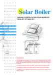
Winding diagram
12
1
4
3
2
6
7
13
8
9
11
5
Z0055.cdr
10
The diagram shows the winding directions of
material and ribbon. Always follow this
diagram when inserting/changing material and
ribbon.
Also pay attention to the diagrams on
the inside of the device lid.
Ribbon and material should only be
inserted/changed by specially instructed
personnel.
Designation of the parts
1
2
3
4
5
6
7
8
9
10
11
12
13
Ribbon roller
Ribbon unwinder
Ribbon take-up
Material unwinder
Material dancer rod
Ribbon dancer rod
Pressure roller
Transport roller
Print roller
Gap photoelectric switch
Material
Print head contact adjuster knob
Print head
02/02 Rev. 2.14-01
USER MANUAL
TTK/Texxtile
Setup , Page 3
Materials
Label material
The TTK is a universal printer for textile, self-adhesive and card labels.
Textile
Non-textile
Textile materials between 15 and 53 mm wide can be processed. The
textile stacker allows for a label length of between 30 and 120 mm.
The TTK is supplied with a textile unit, i.e. textile materials can be
processed up to a maximum width of 53 mm.
The metal sleeve must be removed from the ribbon guide rod before
processing self-adhesive and card labels. The material can have a
maximum width of 53 mm.
A different contact roller must be installed in the print unit and the textile
stacker removed before printing self-adhesive/card labels wider than
53 mm.
Notes about refitting the printer for non-textile material wider than 53 mm
can be found in the section "Processing card/self-adhesive material".
Recommendation
Pay attention to the following 3 factors when selecting the material:
– The abrasive behaviour of the surface structure of the material.
– The properties with regards to the chemical reaction during transfer of
the print colour.
– The temperature required for transferring the colour.
Thermal printing ribbon
Roll dimensions
Ribbon rolls with the following dimensions can be used:
– Outer diameter: maximum 90 mm
– Core diameter: maximum 1" (25.4 mm)
– Width: 30 to 110 mm
Recommendation
The following recommendations are given for ribbons:
– The ribbon reverse must have an anti-static and friction-reducing coating
(backcoating).
– Ribbons must be specifically designed for "flathead-type print heads".
– Ribbons should be suitable for print speeds of up to 12 inch/sec.
Ribbons without these properties can reduce the performance of the printer
or the print quality and also damage the print head!
02/02 Rev. 2.14-01
USER MANUAL
TTK/Texxtile
Setup , Page 4
Inserting label material
1. Cut off the end of the material at an
angle.
2. Pull the guide disc (1) off the material
unwinder.
3. Push the material roll onto the unwinder
using the appropriate adapter ring. T he
material roll should turn in an anticlockwise direction (looking from the
right) when unwinding.
21
4. Push on the outer guide disc of the
unwinder.
5. Guide the material over the bouncer arm
(2) and thread it through the slot
opening (3) in the back of the printer.
Pull the material under the tubular guide
(4).
5
6. Set the material guide to the width of the
label material. To do this, unscrew the
thumb screw (5) on the front material
guide (6) and push the material guide to
the side. Retighten the thumb screw.
Be careful when inserting textile material
– do not press the material together at
the sides
5
2
3
4
3
4
7. Press the lever (7) and adjust the
contact roller (8) as required. T he rollers
should press down on the material as
evenly as possible. Only one of the
contact rollers needs to be used for very
narrow material.
8
8. Push the material up to the contact roller
in the material guide.
8
Continued on the next page.
5
7
6
02/02 Rev. 2.14-01
USER MANUAL
TTK/Texxtile
Setup , Page 5
9. Switch on the device. T he print head
lowers itself a little.
10. Loosen the contact lever (1) of the draw
unit. The contact lever points upwards
when it is loosened.
1
11. Transport the material in an anticlockwise direction up to the stacker by
turning the hand wheel (2) .
12. Close the contact lever of the draw unit.
Do not rest the free hand on the printing
module or the textile stacker. Danger of
injury from the textile stacker cutter!
There is a danger of fingers, hair,
clothing, jewellery etc. being drawn into
the machine in the vicinity of the ribbon
and material transport unit.
Setting the gap photoelectric switch
2
The gap photoelectric switch sits behind the
brake unit (viewed in the direction of transport).
Push the gap photoelectric switch (3) to
the side so that the material runs through.
4
Setting the material brake
The degree of brake force can be set by turning
the red cap nut (4) on the brake unit.
Turning it in a clockwise direction
increases the brake force.
Turning it in an anti-clockwise direction
reduces the brake force.
Set the brake with the lowest possible
brake force for textile materials.
2
3
3
02/02 Rev. 2.14-01
USER MANUAL
TTK/Texxtile
Setup , Page 6
Setting the print head contact
The setting screw for the print head
4
contact (4) for textile material should not
be set any higher than position two (2).
Try a test print with position one (1) first.
Tool
Coin or wide screwdriver
4
1
3
2
02/02 Rev. 2.14-01
USER MANUAL
TTK/Texxtile
Setup , Page 7
Inserting the ribbon
3
Use the adjacent winding diagram for
orientation when inserting the ribbon.
2
1. Open the hood of the printer.
1
2. Push the ribbon roll (1) onto the right
ribbon mandrel (2) so that the ribbon
unrolls in an anti-clockwise direction.
3. Push the empty ribbon sleeve onto the
left mandrel (3).
4. Twisting the beginning of the ribbon
makes it easier to thread in.
z0055a.cdr
5. First of all thread the beginning of the
ribbon past the print head (4), and then
pull it an angle underneath the print
head.
6. Pull the ribbon under the print head and
smoothen it out (6).
Continued on the next page.
3
1
2
4
6
4
02/02 Rev. 2.14-01
USER MANUAL
TTK/Texxtile
7. Guide the ribbon around the ribbon
dancer rod (1) and ribbon roller (2) and
wrap it around the ribbon sleeve (3) as
shown here.
The metal sleeve (2) supplied with the
printer must be pushed over the ribbon
roller when printing with textile
material.
Setup , Page 8
2
3
1
It may be necessary to readjust the
ribbon tautness if the ribbon gets
folded during the printing process.
Setting the ribbon tautness
The rotation torque of the ribbon unwind
mandrel (4) and ribbon roll-up mandrel (5)
can be adjusted using the red plastic
hexagonal screw (6) on the ribbon mandrel.
Increase the rotation torque by turning it in a
clockwise direction.
During feeding, the ribbon must run between
the mandrels evenly and without folds over
the whole length.
Ribbon is slack or has folds, or is not wound
up tightly enough on the roll-up mandrel.
Increase the unwinding/roll-up torque.
The ribbon stretches visibly or tears during
printing. Ribbon is not transported properly.
Increase the unwinding/roll-up torque.
Although the factory settings cover a large
range of varying ribbon widths, slight
adjustment may be necessary when using
very narrow or very wide ribbon.
6
5
6
4
02/02 Rev. 2.14-01
USER MANUAL
TTK/Texxtile
Setup , Page 9
Printing
Switching on the printer
Have you inserted the material and ribbon and carried out all the settings
described in "Commissioning"? If so:
Switch on the mains switch on the back of the printer.
OPEN
Appears because the contact lever of the draw unit was open
for inserting the material
Press the ENTER button.
OFF
Press the ENTER button.
ON
The TTK is now ready for operation.
Setting the print job
Easy Plug
A simple text editor is sufficient for determining a label layout using the
Easy Plug command language, and for sending commands relating to the
print procedure to the printer. An example of this is shown in the following
section "Programming example".
The complete Easy Plug range of commands can be found in the EASY
PLUG MANUAL.
Jetmark
The inexperienced operator will have to frequently refer to the Easy Plug
commands when creating his first print jobs in the text editor. The label
layout software Jetmark is easier to use. The programme allows label
layouts to be created simply by clicking with the mouse in the user
interface.
Transmitting print jobs
There are two ways to send print jobs from the PC to the printer: per data
cable (parallel or serial) or by using a plug-in card.
Per data cable
The simplest way to transmit a print job is to create a text file with the
necessary Easy Plug commands, and then to copy it – in the MS-DOS
window of Windows – onto the appropriate output device.
Example: copy test.txt lpt1
Printer drivers
Another possibility is to set up a printer in Windows using the standard
driver ("Universal/Text only"). The file with the Easy Plug-command can
then be sent to the printer using the print command in the text editor
(file/printing...).
02/02 Rev. 2.14-01
USER MANUAL
TTK/Texxtile
Setup , Page 10
A printer must be set up in Windows using the special TTK driver in order to
print with Jetmark. Drivers are included on the documentation CD supplied
with the printer.
Per plug-in card
Print jobs can also be transmitted to the TKK using a plug-in card. There
are two plug-in card slots on the back of the printer. Not only print jobs, but
also for example fonts, logos or bar codes can be stored on plug-in cards.
A plug-in card with a special character set for laundry symbols is supplied
with the TTK. A summary of the characters and their use is given on a
separate information sheet.
Notes about the different plug-in card types and their application
possibilities can be found in the card manual.
02/02 Rev. 2.14-01
USER MANUAL
TTK/Texxtile
Setup , Page 11
Programming example
No. Easy Plug code
1
2
3
4
5
6
7
8
9
10
11
12
13
14
15
#!A1
#IMN50.0/100.0
Example, comment
Activate interface
Material information (here: reel material
without gaps, 50 mm wide, 100 mm
long)
#ERY1
Start label format (change label
according to series; cut after every label)
#J66.0#T15.0#M2/2#YT107/0///TTK
Text field "TTK"
#J60.0#T14.0#M1/1#YT106/0///Textile Printer
Text field "Textile Printer"
#J53.5#T10.0#YT104/0///T he easy way
Text field "T he easy way"
#J48.0#T15.0#YT104/0///to create your
Text field "to create your"
#J42.5#T20.0#YT104/0///textile labels
Text field "textile labels"
1)
#J25.0#T10.0#YB1/0M/10/3///1234567890
Bar code field
#J15.0#T8.0M1/1#YT104/0///PRICE
Text field "PRICE"
#J15.0#T30.0#M2/2#YT106/0///120,95
Text field "120,95"
#J10.0#T5.0#M1/1#YT103/1///90-degree rotation Text field "90-degree rotation"
#J7.0#T45.0#YT104/2///180-degree rotation
Text field "180-degree rotation"
#Q5/
End label format, print quantity: 5
#CIM
Cut
1) Condition: parameter PRTP/BCHI = 1
The above Easy Plug code – sent to a TKK
printer as a pure text file – produces five
printouts as shown on the right (in line 14
the print quantity is set at 5).
Change label
A cut follows each printed label (line 3). T he
fifth label is pushed forwards a little further
than the other labels before being cut. It
then protrudes out of the label stack and
marks the end of a print series (defined in
line 3). How far the so-called change label
protrudes out of the stack can be set using
the parameter PRTP/CLEN in a range of
between 0 and 30 mm.
You can find a summary of all the
parameters and settings in the chapter
"Info Print-outs and Parameters".
02/02 Rev. 2.14-01
USER MANUAL
TTK/Texxtile
Setup , Page 12
Index
P
B
Brake torque, ribbon .....................................8
Brake unit, setting.........................................5
Part names....................................................2
Photoelectric switch, gap..............................5
Print head contact, adjusting........................6
Print job, setting............................................9
Print jobs, transmitting..................................9
Print quality ...................................................3
C
Change label...............................................11
D
Designation of the parts................................2
E
Easy Plug, sample label .............................11
Example, label layout..................................11
G
Gap photoelectric switch...............................5
I
Inserting label material..................................4
Inserting material ..........................................4
Inserting material and ribbon, diagram.........2
L
Label material ...............................................3
Laundry symbols.........................................10
M
Material brake, setting ..................................5
Material guide, setting...................................4
Metal sleeve on ribbon roller ........................8
R
Ribbon roller, metal sleeve for .....................8
Ribbon selection...........................................3
Ribbon slack .................................................8
Ribbon tautness, setting...............................8
Ribbon tears .................................................8
Ribbon, inserting...........................................7
Roll-up speed, ribbon ...................................8
S
Switching on, printer .....................................9
T
Textile labels.................................................3
Transport unit................................................5
W
Winding diagram...........................................2