1
Cat.No.V108-E1-03 NB-series NB3Q-TWB NB5Q-TWB NB7W-TWB NB10W-TW01B Programmable Terminals HOST CONNECTION MANUAL OMRON, 2012 All rights reserved. No part of this publication may be reproduced, stored in a retrieval system, or transmitted, in any form, or by any means, mechanical, electronic, photocopying, recording, or otherwise, without the prior written permission of OMRON. No patent liability is assumed with respect to the use of the information contained herein. Moreover, because OMRON is constantly striving to improve its high-quality products, the information contained in this manual is subject to change without notice. Every precaution has been taken in the preparation of this manual. Nevertheless, OMRON assumes no responsibility for errors or omissions. Neither is any liability assumed for damages resulting from the use of the information contained in this publication. NB-series NB3Q-TW B NB5Q-TW B NB7W-TW B NB10W-TW01B Programmable Terminals Host Connection Manual Revised August 2012 Introduction Thank you for purchasing an NB-series Programmable Terminal. NB-Series Programmable Terminals (PTs) are designed to handle information generated in FA production sites. Be sure to understand the functions and performances etc thoroughly before using PT correctly. Intended Audience This manual is intended for the following personnel, who must also have knowledge of electrical systems (an electrical engineer or the equivalent). • Personnel in charge of introducing FA systems into production facilities. • Personnel in charge of designing FA systems. • Personnel in charge of installing and connecting FA facilities. • Personnel in charge of managing FA systems and facilities General Precautions • The user must operate the product according to the performance specifications described in the operation manuals. • Do not use the PT touch switch input functions for applications where danger to human life or serious property damage is possible, or for emergency switch applications. • Before using the product under conditions which are not described in the manual or applying the product to nuclear control systems, railroad systems, aviation systems, vehicles, combustion systems, medical equipment, amusement machines, safety equipment, and other systems, machines and equipment that may have a serious influence on lives and property if used improperly, consult your OMRON representative. • Make sure that the ratings and performance characteristics of the product are sufficient for the systems, machines, and equipment, and be sure to provide the systems, machines, and equipment with double safety mechanisms. • This manual provides information for connecting and setting up an NB-Series PT. Be sure to read this manual before attempting to use the PT and keep this manual close at hand for reference during installation and operation. NB-series Programmable Terminals Host Connection Manual(V108) 1 NB-series Manuals NB-series manuals are organized in the sections listed in the following tables. Refer to the appropriate section in the manuals as required. Programmable Terminals Host Connection Manual (Cat. No. V108) (This Manual) Section Contents Section 1 List for All PLCs Supported by NB series This section lists all PLCs supported by NB Units. Section 2 Connecting to SIEMENS PLCs This section describes the connection to SIEMENS PLCs. Section 3 Connecting to Mitsubishi PLCs This section describes the connection to Mitsubishi PLCs. Section 4 Connecting to Schneider PLCs This section describes the connection to Schneider PLCs. Section 5 Modbus Connection This section describes the connection on Modbus protocol. Section 6 Connecting to Delta PLCs This section describes the connection to Delta PLCs. Section 7 Connecting to LG PLCs This section describes the connection to LG PLCs. Section 8 Connecting to Panasonic PLCs This section describes the connection to Panasonic PLCs. Section 9 Connecting to AllenBradley (Rockwell) PLC This section describes the connection to Allen-Bradley PLC. Section 10 Connecting to PLC of GE Fanuc Automation Inc. This section describes the connection to PLC of GE Fanuc Automation Inc. Programmable Terminals NB-Designer Operation Manual (Cat. No. V106) Section 2 Contents Section 1 Introduction This section provides an outline of the NB-series PTs, including their functions, features, connection types and communication methods. Section 2 Installation and Startup of NB-Designer This section describes how to install and start the NB-Designer. Section 3 Functions of NB-Designer This section describes the functions of NB-Designer. Section 4 Functions of NBManager This section describes the functions of NBManager. Section 5 Maintenance and Abnormality Handling This section describes the maintenance and check to prevent the abnormality occurrence and the handling of the abnormalities occurred in NB Unit. Section 6 Descriptions of New Functions Added into NBTW01B This section describes the new functions added into NB-TW01B, the system attributes and the component attributes. Appendices The appendices provide lists of the NB Units, the Communication Units, the applicable PLCs, and the list of NB-Designer functions. NB-series Programmable Terminals Host Connection Manual(V108) Programmable Terminals Setup Manual (Cat. No. V107) Section Contents Section 1 Part Names and Functions This section describes the names and functions of the various parts of an NB Unit. Section 2 Installing the NB Unit and Connecting Peripheral Devices This section describes the methods used to install the NB Unit and connect peripheral devices. Section 3 System Setting Mode This section describes the System Setting Mode. Section 4 Calibrate Mode This section describes the Calibrate Mode. Appendices The appendices provide information on specifications, dimensions, wirings, and lists of the NB Units, the applicable PLCs and options. Programmable Terminals Startup Guide Manual (Cat. No. V109) Section Contents Section 1 NB Overview This section provide specifications of the NB Unit, describes its names and functions of the various parts. Section 2 System Design This section describes the manual structure, takes NB7W as an example to introduce the operation procedures of the NB system. Section 3 Installation and Wiring This section describes how to install and wire the NB Unit. Section 4 Screen Creation This section describes how to create a demonstration project through NB-Designer. Section 5 Run This section describes how to start running at the Host side and prepare to send screen data to NB7W. Section 6 Maintenance and Troubleshooting This section describes the maintenance and inspection methods for preventing errors occurring, and troubleshooting measures when errors occur. WARNING Failure to read and understand the information provided in this manual may result in personal injury or death, damage to the product, or product failure. Please read each section in its entirety and be sure you understand the information provided in the section and related sections before attempting any of the procedures or operations given. NB-series Programmable Terminals Host Connection Manual(V108) 3 Manual Structure Page Structure and Icons The following page structure and icons are used in this manual. Level 1 heading Level 2 heading Level 3 heading 2 Installing the NB Unit and Connecting Peripheral Devices Level 3 heading 2-1-2 Installation onto the Operation Panel Use the metal kit and tool (a crosshead screwdriver) supplied with the Unit for installation. Proceed the installation following the procedures below. Step in a procedure 1 Panel cutout with dimensions is shown below. Fit the NB Unit into the panel from the front side. Width Indicates a step in a procedure. 2-1 Installing the NB Unit Install the NB Unit by embedding it into the operation panel. 2 Height Models NB3Q-TW00B/TW01B NB5Q-TW00B/TW01B 2 Opening Dimension (W H mm) 119.0(+0.5/-0) 93.0(+0.5/-0) 172.4(+0.5/-0) 131.0(+0.5/-0) NB7W-TW00B/TW01B 191.0(+0.5/-0) 137.0(+0.5/-0) NB10W-TW01B 258.0(+0.5/-0) 200.0(+0.5/-0) As follows, insert panel fixators at the locations indicated by red box around the back of the NB Unit. Insert the hooks of positioners into the square holes on the Unit to hold the fixators properly, and tighten the screws firmly with the screwdriver. 2-1-2 Installation onto the Operation Panel Opening dimensions Gives the current headings. Page tab Gives the number of the section. NB5Q/NB7W-TWB Special Information (See below.) Icons are used to indicate precautions and additional information. Precautions for Safe Use • When operating on the operation panel, make sure to keep metal particles from entering the Unit. The mounting panel must be between 1.6 and 4.8 mm thick. The NB Unit must be installed in a control panel. For the sake of waterproof and dustproof, all the fixators must be evenly tightened to a torque of 0.5~0.6 Nm. If the tightening torque exceeds the specified value, or the tightening is not even, deformation of the front panel may occur. Make sure that the operation panel is clean, unbent, and strong enough for the installation process. Manual name 2-3 NB-series Programmable Terminals Setup Manual(V107) This illustration is provided only as a sample and may not literally appear in this manual. Special Information Special information in this manual is classified as follows: Precautions for Safe Use Precautions on what to do and what not to do to ensure using the product safely. Precautions for Correct Use Precautions on what to do and what not to do to ensure proper operation and performance. Additional Information Additional information to increase understanding or make operation easier. 4 NB-series Programmable Terminals Host Connection Manual(V108) Terminology The following terminology is used in this manual. Terms Descriptions NB Unit Indicates the main Unit of the products in the OMRON NB Series of Programmable Terminal. NB Series Indicates products in the OMRON NB Series of Programmable Terminal. In this manual, unless otherwise specified, NB Series is taken as the subject concerned. PLC Indicates a Programmable Controller. CP Series Indicates the following products in the OMRON CP Series of Programmable Controllers: CP1H, CP1L, CP1E CS/CJ Series Indicates the following products in the OMRON CS/CJ Series of Programmable Controllers: CS1G, CS1H, CS1G-H, CS1H-H, CJ1G, CJ1M, CJ2M, CJ2H C Series Indicates the following products in the OMRON C Series of Programmable Controllers: C200HX(-Z), C200HG(-Z), C200HE(-Z), CQM1, CQM1H, CPM1A, CPM2A, CPM2C Serial Communication Unit Indicates a Serial Communication Unit for an OMRON SYSMAC CS/CJ-Series PLC. Serial Communication Board Indicates a Serial Communication Board for an OMRON SYSMAC CS/CJ-Series PLC. Communication Board Indicates a Communication Board for an OMRON C200HX/HG/HE(-Z) PLC. CPU Unit Indicates a CPU Unit in the OMRON CP, CS/CJ or SYSMAC C Series of Programmable Controllers. NB-Designer Indicates the OMRON NB-Designer. Host Indicates the PLC and other units functioning as the control devices for NB-Series Units. PT Indicates an OMRON Programmable Terminal. HMI Indicates an OMRON Programmable Terminal. NB-series Programmable Terminals Host Connection Manual(V108) 5 6 NB-series Programmable Terminals Host Connection Manual(V108) CONTENTS Introduction............................................................................................................... 1 NB-series Manuals.................................................................................................... 2 Manual Structure ...................................................................................................... 4 Terminology .............................................................................................................. 5 Safety Precautions ................................................................................................. 14 Precautions for Safe Use ....................................................................................... 16 Precautions for Correct Use .................................................................................. 18 Conformance to EC Directives .............................................................................. 19 Related Manuals ..................................................................................................... 20 Sec. 1 List for All PLCs Supported by NB Series ........................... 1-1 1-1 Lists for Supported PLC.......................................................... 1-2 1-2 Definition and Description of Serial Port COM ..................................................................... 1-5 Sec. 2 Connecting to SIEMENS PLCs ............................................. 2-1 2-1 Serial Port Communication..................................................................................................... 2-2 2-2 Serial Port Communication Parameters and Cable Fabrication.......................................... 2-3 2-3 2-4 2-5 Sec. 3 Serial Port Communication Parameter Setting ..................................................................... 2-4 2-3-1 When Using SIEMENS S7-200 Communication Protocol .......................................................... 2-4 2-3-2 When Using SIEMENS S7-300/400 (PC Adapter Direct) Communication Protocol................... 2-5 Supported Registers ............................................................................................................... 2-8 2-4-1 SIEMENS S7-200 ....................................................................................................................... 2-8 2-4-2 SIEMENS S7-300/400 (PC Adapter Direct)................................................................................ 2-9 Cable Fabrication................................................................................................................... 2-10 Connecting to Mitsubishi PLCs............................................ 3-1 3-1 Serial Port Communication..................................................................................................... 3-2 3-2 Serial Port Communication Parameters and Cable Fabrication.......................................... 3-4 3-3 Serial Port Communication Parameter Setting ..................................................................... 3-5 3-3-1 When Using Mitsubishi FX1S, Mitsubishi FX0N/1N/2N/3G and Mitsubishi FX3U Communication Protocols3-5 3-3-2 When Using Mitsubishi FX-485ADP/485BD/232BD (Multi-station) Communication Protocols .. 3-7 3-3-3 When Using FX2N-10GM/20GM Communication Protocol ...................................................... 3-10 3-3-4 When Using Mitsubishi Q00J (CPU Port) Communication Protocol......................................... 3-11 3-3-5 When Using Mitsubishi Q series (CPU Port) Communication Protocol .................................... 3-11 3-3-6 When Using Mitsubishi Q06H Communication Protocol........................................................... 3-12 3-3-7 When Using Mitsubishi Q_QnA (Link Port) Communication Protocol ...................................... 3-13 3-4 Supported Registers ............................................................................................................. 3-18 3-5 Cable Fabrication................................................................................................................... 3-21 NB-series Programmable Terminals Host Connection Manual(V108) 7 Sec. 4 Connecting to Schneider PLCs ............................................ 4-1 4-1 Serial Port Communication..................................................................................................... 4-2 4-2 Communication Parameters and Cable Fabrication............................................................. 4-3 4-3 Communication Parameter Setting ........................................................................................ 4-4 4-4 Supported Registers ............................................................................................................. 4-13 4-5 Cable Fabrication................................................................................................................... 4-14 Sec. 5 Modbus Connection .............................................................. 5-1 5-1 Serial Port and Network Interface Communication .............................................................. 5-2 5-2 Communication Parameters and Cable Fabrication............................................................. 5-3 5-3 Communication Parameter Setting ........................................................................................ 5-4 5-4 Supported Registers ............................................................................................................... 5-7 5-5 Cable Fabrication..................................................................................................................... 5-9 5-6 Modbus Protocol .................................................................................................................. 5-10 5-7 Sec. 6 Introduction to Modbus Protocol ............................................................................................... 5-10 5-6-2 When NB adopts Modbus TCP protocol (Master/Slave mode) ................................................. 5-11 Example of NB as Modbus Slave ......................................................................................... 5-12 Connecting to Delta PLCs..................................................... 6-1 6-1 Serial Port Communication..................................................................................................... 6-2 6-2 Communication Parameters and Cable Fabrication............................................................. 6-3 6-3 Communication Parameter Setting ........................................................................................ 6-4 6-4 Supported Registers ............................................................................................................... 6-6 6-5 Cable Fabrication..................................................................................................................... 6-7 Sec. 7 Connecting to LG PLCs......................................................... 7-1 7-1 Serial Port Communication ........................................................7-2 7-2 Communication Parameters and Cable Fabrication..................................7-3 7-3 Communication Parameter Setting ........................................................................................ 7-4 7-4 Supported Registers ............................................................................................................... 7-9 7-5 Cable Fabrication................................................................................................................... 7-11 Sec. 8 8 5-6-1 Connecting to Panasonic PLCs............................................ 8-1 8-1 Serial Port Communication ........................................................8-2 8-2 Communication Parameters and Cable Fabrication..................................8-3 8-3 Communication Parameter Setting.................................................8-4 8-4 Supported Registers ............................................................................................................... 8-5 8-5 Cable Fabrication..................................................................................................................... 8-6 NB-series Programmable Terminals Host Connection Manual(V108) Sec. 9 Connecting to Allen-Bradley (Rockwell) PLC...................... 9-1 9-1 Serial Port Communication..................................................................................................... 9-2 9-2 Serial Port Communication Parameters and Cable Fabrication.......................................... 9-3 9-3 Serial Port Communication Parameter Setting ..................................................................... 9-4 9-4 Supported Registers ............................................................................................................... 9-9 9-5 Cable Fabrication................................................................................................................... 9-10 Sec. 10 Connecting to PLC of GE Fanuc Automation Inc. ............ 10-1 10-1 Serial Port Communication................................................................................................... 10-2 10-2 Serial Port Communication Parameters and Cable Fabrication........................................ 10-3 10-3 Serial Port Communication Parameter Setting ................................................................... 10-4 10-4 Supported Registers ............................................................................................................. 10-7 10-5 Cable Fabrication................................................................................................................... 10-8 Revision History ....................................................................................................... 1 NB-series Programmable Terminals Host Connection Manual(V108) 9 10 NB-series Programmable Terminals Host Connection Manual(V108) Read and Understand this Manual Please read and understand this manual before using the product. Please consult your OMRON representative if you have any questions or comments. Warranty and Limitations of Liability WARRANTY OMRON’s exclusive warranty is that the products are free from defects in materials and workmanship for a period of one year (or other period if specified) from date of sale by OMRON. OMRON MAKES NO WARRANTY OR REPRESENTATION, EXPRESS OR IMPLIED, REGARDING NONINFRINGEMENT, MERCHANTABILITY, OR FITNESS FOR PARTICULAR PURPOSE OF THE PRODUCTS. ANY BUYER OR USER ACKNOWLEDGES THAT THE BUYER OR USER ALONE HAS DETERMINED THAT THE PRODUCTS WILL SUITABLY MEET THE REQUIREMENTS OF THEIR INTENDED USE. OMRON DISCLAIMS ALL OTHER WARRANTIES, EXPRESS OR IMPLIED. LIMITATIONS OF LIABILITY OMRON SHALL NOT BE RESPONSIBLE FOR SPECIAL, INDIRECT, OR CONSEQUENTIAL DAMAGES, LOSS OF PROFITS OR COMMERCIAL LOSS IN ANY WAY CONNECTED WITH THE PRODUCTS, WHETHER SUCH CLAIM IS BASED ON CONTRACT, WARRANTY, NEGLIGENCE, OR STRICT LIABILITY. In no event shall the responsibility of OMRON for any act exceed the individual price of the product on which liability is asserted. IN NO EVENT SHALL OMRON BE RESPONSIBLE FOR WARRANTY, REPAIR, OR OTHER CLAIMS REGARDING THE PRODUCTS UNLESS OMRON’S ANALYSIS CONFIRMS THAT THE PRODUCTS WERE PROPERLY HANDLED, STORED, INSTALLED, AND MAINTAINED AND NOT SUBJECT TO CONTAMINATION, ABUSE, MISUSE, OR INAPPROPRIATE MODIFICATION OR REPAIR. NB-series Programmable Terminals Host Connection Manual(V108) 11 Application Considerations SUITABILITY FOR USE OMRON shall not be responsible for conformity with any standards, codes, or regulations that apply to the combination of products in the customer’s application or use of the products. At the customer’s request, OMRON will provide applicable third party certification documents identifying ratings and limitations of use that apply to the products. This information by itself is not sufficient for a complete determination of the suitability of the products in combination with the end product, machine, system, or other application or use. The following are some examples of applications for which particular attention must be given. This is not intended to be an exhaustive list of all possible uses of the products, nor is it intended to imply that the uses listed may be suitable for the products: • Outdoor use, uses involving potential chemical contamination or electrical interference, or conditions or uses not described in this manual. • Nuclear energy control systems, combustion systems, railroad systems, aviation systems, medical equipment, amusement machines, vehicles, safety equipment, and installations subject to separate industry or government regulations. • Systems, machines, and equipment that could present a risk to life or property. Please know and observe all prohibitions of use applicable to the products. NEVER USE THE PRODUCTS FOR AN APPLICATION INVOLVING SERIOUS RISK TO LIFE OR PROPERTY WITHOUT ENSURING THAT THE SYSTEM AS A WHOLE HAS BEEN DESIGNED TO ADDRESS THE RISKS, AND THAT THE OMRON PRODUCTS ARE PROPERLY RATED AND INSTALLED FOR THE INTENDED USE WITHIN THE OVERALL EQUIPMENT OR SYSTEM. PROGRAMMABLE PRODUCTS OMRON shall not be responsible for the user’s programming of a programmable product, or any consequence thereof. 12 NB-series Programmable Terminals Host Connection Manual(V108) Disclaimers CHANGE IN SPECIFICATIONS Product specifications and accessories may be changed at any time based on improvements and other reasons. It is our practice to change model numbers when published ratings or features are changed, or when significant construction changes are made. However, some specifications of the products may be changed without any notice. When in doubt, special model numbers may be assigned to fix or establish key specifications for your application on your request. Please consult with your OMRON representative at any time to confirm actual specifications of purchased products. DIMENSIONS AND WEIGHTS Dimensions and weights are nominal and are not to be used for manufacturing purposes, even when tolerances are shown. PERFORMANCE DATA Performance data given in this manual is provided as a guide for the user in determining suitability and does not constitute a warranty. It may represent the result of OMRON’s test conditions, and the users must correlate it to actual application requirements. Actual performance is subject to the OMRON Warranty and Limitations of Liability. ERRORS AND OMISSIONS The information in this manual has been carefully checked and is believed to be accurate; however, no responsibility is assumed for clerical, typographical, or proofreading errors, or omissions. NB-series Programmable Terminals Host Connection Manual(V108) 13 Safety Precautions Notation Used for Safety Information The following notation is used in this manual to provide precautions required to ensure safe usage of the product. The safety precautions that are provided are extremely important to safety. Always read and heed the information provided in all safety precautions. WARNING Indicates an imminently hazardous situation which, if not avoided, will result in death or serious injury. Additionally, there may be severe property damage. Precautions for Safe Use Indicates precautions on what to do and what not to do to ensure using the product safely. Precautions for Correct Use Indicates precautions on what to do and what not to do to ensure proper operation and performance. Note Indicates suggestive information and precautions on operation of the product. Symbols • Prohibition Indicates a general prohibition. • Caution Indicates general cautionary, warning, or danger level information. 14 NB-series Programmable Terminals Host Connection Manual(V108) WARNING Do not attempt to take the product apart and do not touch the product inside while the power is being supplied. Otherwise it may result in electric shock. Always ensure that the personnel in charge confirm that installation, inspection, and maintenance were properly performed for the NB Unit. “Personnel in charge” refers to individuals qualified and responsible for ensuring safety during machine design, installation, operation, maintenance, and disposal. Ensure that installation and post-installation checks are performed by personnel in charge who possess a thorough understanding of the machinery to be installed. Do not use the input functions of the touch switch, etc. of the NB Unit, in applications that involve human life, in applications that may result in serious injury, or for emergency stop switches. Do not attempt to disassemble, repair, or modify the NB Unit. Otherwise it may impair the safety functions. Never press more than two points on the touch panel of the NB Unit at a time. Otherwise, it may activate a switch somewhere between the two points. NB-series Programmable Terminals Host Connection Manual(V108) 15 Precautions for Safe Use • When unpacking the NB Units and the peripheral devices, check carefully for any external scratches or other damages. Also, shake the Units gently and check for any abnormal sound. • The NB Unit must be installed in a control panel. • The mounting panel must be between 1.6 and 4.8 mm thick. Tighten the Mounting Brackets evenly to a torque of between 0.5 and 0.6 Nxm to maintain water and dust resistance. If the tightening torque exceeds the specified value, or the tightening is not even, deformation of the front panel may occur. What is more, make sure the panel is not dirty or warped and that it is strong enough to hold the Units. • Do not let metal particles enter the Units when preparing the panel. • Do not connect an AC power supply to the DC power terminals. • Use a DC power with a slight voltage fluctuation and that will provide a stable output even if the input is momentarily interrupted for 10 ms. Rated Power Supply Voltage: DC 24 V (Allowable range DC 20.4 ~ 27.6 V) • Do not perform a dielectric voltage test. • Making the connection by using terminal screws crimping on a twisted-pair cable with a crimping range of 12~26 AWG, and only 6.5 mm of insulation peel of the cable needs to be peeled off. Tighten the terminal screws at a torque of between 0.3 and 0.5 Nxm. Make sure the screws are properly tightened. • To prevent malfunctions caused by noise, ground the Unit correctly. • Do not touch the packaging part of the circuit board with your bare hands. Discharge any static electricity from your body before handling the board. • When using the No. 6 pin of the serial communication port COM1 connector for a voltage of DC+5V, make sure the supply equipment’s current capacity is below 250mA before using it. The DC+5V voltage output of the NB unit is +5V±5%, and the maximum current is 250mA. (The serial communication port COM1 of NB3Q-TW00B and NB3Q-TW01B is unable to output the current.) • Turn OFF the power supply before connecting or disconnecting cables. • Always keep the connector screws firmly tightened after the communication cable is connected. • The maximum tensile load for cables is 30 N. Do not apply loads greater than this. • Confirm the safety of the system before turning ON or OFF the power supply, or pressing the reset button. • The whole system may stop depending on how the power supply is turned ON or OFF. Turn ON/OFF the power supply according to the specified procedure. • Reset by pressing the reset button, or restart the power supply, once the DIP switch settings are changed. • To ensure the system’s safety, make sure to incorporate a program that can confirm the normal functionality of the NB Unit before running the system. • Start actual system application only after sufficiently checking screen data, macros and the operation of the program at the host side. • Do not press the touch panel with a force greater than 30 N. • Do not use hard or pointed objects to operate or scrub the screen, otherwise, the surface of the screen may be damaged. • Confirm the safety of the system before pressing the touch panel. • Signals from the touch switches may not be input if the touch switches are pressed consecutively at high speed. Confirm each input before proceeding to the next one. • Do not accidentally press the touch panel when the backlight is not lit or when the display does not appear. Make sure of the safety of the system before pressing the touch panel. • To use numeric input functions safely, always make maximum and minimum limit settings. • Before initializing screen data, confirm that existing data is backed up at the NB-Designer. 16 NB-series Programmable Terminals Host Connection Manual(V108) • When changing the password with the screen, do not reset or turn OFF the power supply until writing is finished. Failure to save the password may cause the screen to fail to function. • When using an equipment monitor, confirm the safety of the system before carrying out the following operations: • Changing monitor data. • Changing operation mode. • Forced setup/reset. • Changing the current value or the set value. • Do not connect a USB connector to any device that is not applicable. • When connecting the equipment with the USB HOST connector, make sure the supply equipment's current capacity is below 150mA before using it. The DC+5V voltage output of the NB Unit is +5V±5%, and the maximum current is 150mA. • Before connecting a USB connector to a device, make sure that the device is free of damage. • Commercially available and the recommended USB HUBs are different from the general specifications of the NB Unit. The unit may not function well in an environment subject to noise, static electricity. Therefore, when using a USB HUB, employ sufficient noise and static electricity insulation measures, or install it at a site free of noise or static electricity. • While uploading or downloading screen data or system programs, do not perform the following operations that may corrupt the screen data or the system program: • Turning OFF the power supply of the NB Unit. • Pressing the PT’s reset switch. • Dispose of the Units and batteries according to local ordinances as they apply. • When exporting products with lithium primary batteries containing perchlorate at 6ppb or above to or delivering them through California, USA, the following precautionary measures have to be publicized. Perchlorate material - applicable through special processing. Refer to http://www.dtsc.ca.gov/hazardouswaste/perchlorate. NB-Series products contain lithium primary batteries. When exporting products containing this kind of batteries to or delivering them through California, USA, label all the product packages as well as the appropriate delivery packages. • Do not use benzene, paint thinner, or other volatile solvents, and do not use chemically treated cloths. • Do not dispose the Units together with general waste at waste yards. When disposing them, follow the related local ordinances or rules. • Customers may not replace the backlight lamp inside the NB Unit. Please contact OMRON’s customer service center. • Deterioration over time can cause the touch points to move. Calibrate the touch panel periodically. • Water and oil resistance will be lost if the front sheet is torn or is peeling off. Do not use the Unit, if the front sheet is torn or is peeling off. • The rubber packing will deteriorate, shrink, or harden depending on the operating environment. Inspect and replace the rubber packing periodically. • The communication cables of the COM1 and COM2 connectors are not interchangeable. Confirm the pins of the ports before carrying out communications. (NB3Q-TW00B and NB3Q-TW01B only have COM1.) • Periodically check the installation conditions in applications where the PT is subject to contact with oil or water. • Do not perform the following operations during the communication of the USB memory: • Turning off the power supply of the NB Unit. • Pressing the Reset button on the NB Unit. • Removing the USB memory. • Do not use the USB memory in the environment subject to strong vibration. NB-series Programmable Terminals Host Connection Manual(V108) 17 Precautions for Correct Use • Do not install the unit in any of the following locations: Locations subject to severe changes in temperature Locations subject to temperatures or humidity outside the range specified in the specifications Locations subject to condensation as the result of high humidity Locations subject to corrosive or flammable gases Locations subject to strong shock or vibration Locations outdoors subject to direct wind and rain Locations subject to strong ultraviolet light Locations subject to dust Locations subject to direct sunlight Locations subject to splashing oil or chemicals • Take appropriate and sufficient countermeasures when installing systems in the following locations: Locations subject to static electricity or other forms of noise Locations subject to strong electric field or magnetic field Locations close to power supply lines Locations subject to possible exposure to radioactivity • Precautions for software: The update, restoration, uninstall and reinstallation of software in running status is prohibited in order to guarantee the correct use of the product. 18 NB-series Programmable Terminals Host Connection Manual(V108) Conformance to EC Directives NB-Series Programmable Terminals are EMC compliant. Concepts OMRON products are electronic devices that are incorporated in machines and manufacturing installations. OMRON PTs conform to the related EMC Directives (see note) so that the devices and machines into which they are built can more easily conform to EMC Directives. The actual products have been through inspections and are completely in accordance with EMC directives. However, when they are built into customers’ systems, whether the systems also comply with these Directives is up to the customers for further inspection. EMC-related performance of OMRON PTs will vary depending on the configuration, wiring, and other conditions of the OMRON equipment or control panel. The customer must, therefore, perform final checks to confirm that the overall machine or device conforms to EMC standards. Note The applicable EMC (Electromagnetic Compatibility) standards are as follows: EMS (Electromagnetic sensitivity): EN61131-2: 2007 EMI (Electromagnetic Interference): EN61131-2: 2007 Conformance to EC Directives NB-Series Programmable Terminals are EC compliant. Heed the following precautions in order to ensure that the customer’s overall machine and device conform to EC Directives. 1 2 3 4 The PT must be installed in a control panel. You must use reinforced insulation or double insulation for the DC power supply and the DC power supply must have minimal voltage fluctuations and provide a stable output even if the power supply input is interrupted for 10 ms. The PTs conform to the standard EN 61131-2, but radiated emission characteristics (10m regulations) may vary depending on the configuration of the control panel used, other devices connected to the control panel, wiring, and other conditions. You must therefore confirm that the overall machine or equipment complies with EC Directives. This is a Class A product (Product for industry purpose). It may cause radio interference in residential areas, in which case the user may be required to take adequate measures to reduce interference. NB-series Programmable Terminals Host Connection Manual(V108) 19 Related Manuals The related manuals are as follows: Devices and Software NB series PLC Manual Name Manual No. NB Series NB-Designer Operation Manual V106 NB Series Setup Manual V107 NB Series Host Connection Manual (This manual) V108 NB Series Startup Guide V109 SYSMAC CP Series CP1L CPU Unit Operation Manual W462 SYSMAC CP Series CP1H/L CPU Unit Programming Manual W451 SYSMAC CP Series CP1H CPU Unit Operation Manual W450 SYSMAC CP Series CP1E CPU Unit Hardware USER’S Manual W479 SYSMAC CP Series CP1E CPU Unit Software USER’S Manual W480 SYSMAC C200HX/HG/HE(-E/-ZE) Installation Guide W302 SYSMAC C200HX/HG/HE Operation Manual W303 SYSMAC C200HX/HG/HE(-ZE) Operation Manual W322 SYSMAC CPM1A Operation Manual W317 SYSMAC CPM2A Operation Manual W352 SYSMAC CPM1/CPM1A/CPM2A/CPM2C/SRM1(-V2) Programming Manual W353 SYSMAC CPM2C Operation Manual W356 SYSMAC CS1 Series CS1G/H Operation Manual W339 SYSMAC CS/CJ Series Serial Communications Boards and Serial Communications Units Operation Manual W336 SYSMAC CJ Series CJ1G/H(-H) CJ1M CJ1G Operation Manual W393 SYSMAC CS/CJ Series Programming Manual W394 SYSMAC CS/CJ Series INSTRUCTIONS Reference Manual W340 SYSMAC CS/CJ Series Programming Consoles Operation Manual W341 SYSMAC CS/CJ Series Communications Commands Reference Manual W342 SYSMAC CJ Series CJ2 CPU Unit Hardware USER’S Manual W472 SYSMAC CJ Series CJ2 CPU Unit Software USER’S Manual W473 SYSMAC CS/CJ Series CS1W/CJ1W-ETN21 (100Base-TX) Ethernet Units Operation Manual Construction of Networks W420 SYSMAC CS/CJ Series CS1W/CJ1W-ETN21 (100Base-TX) Ethernet Units Operation Manual Construction of Applications W421 SYSMAC CS/CJ Series CS1W/CJ1W-EIP21 (100Base-TX) EtherNet/IP Units Operation Manual W465 SYSMAC CP Series CP1L-EL/EM CPU Unit Operation Manual W516 External Tool 20 CX-Programmer Ver.9. Operation Manual W446 NB-series Programmable Terminals Host Connection Manual(V108) 1 List for All PLCs Supported by NB Series This section lists all PLCs supported by NB Units. 1-1 Lists for Supported PLC . . . . . . . . . . . . . . . . . . . . . . . . . . . . . . . . . . . . . . . . 1-2 1-2 Definition and Description of Serial Port COM . . . . . . . . . . . . . . . . . . . . . . 1-5 NB-series Programmable Terminals Host Connection Manual(V108) 1-1 1 List for All PLCs Supported by NB Series 1-1 Lists for Supported PLC Names Displayed in NB-Designer AB CompactLogix/ControlLogix Series(DF1) PLC Models CompactLogix 1769-L20 PLC Manufacturers Allen-Bradley(AB) CompactLogix 1769-L30 CompactLogix 1769-L31 CompactLogix 1769-L32E CompactLogix 1769-L35E ControlLogix 1756-L61 ControlLogix 1756-L63 AB SLC500/PLC5/MicroLogix Series(DF1) MicroLogix 1000/1200/1400/1500 SLC 5/03 SLC 5/04 SLC 5/05 PLC-5 11 PLC-5 20 PLC-5 30 PLC-5 40/40L PLC-5 60/60L Delta DVP DVP-xxES/EX/SS Delta DVP-xxSA/SX/SC DVP-xxEH/EH2/SV GE Fanuc Series SNP IC693CPU311/313 GE IC693CPU321/323 IC693CPU331/340/341 IC693CPU350/351/352 IC693CPU360/363/364/374 IC693CSE311 IC693CSE313 IC693CSE323 IC693CSE331 IC693CSE340 GE SNP-X IC693CPU311/313/321/323 IC693CPU331/340/341 IC693CPU350/351/352 IC693CPU360/363/364/374 CPU001/002/005 CPUE05 IC200UAL004/005/006 IC200UDD110/120/212 IC200UDR005/006/010 IC200UAA007 IC200UAR028 IC693CMM311 1-2 NB-series Programmable Terminals Host Connection Manual(V108) 1 List for All PLCs Supported by NB Series LS Master-K Cnet PLC Models K120s PLC Manufacturers LG K200s LS Master-K CPU Direct K120s K200s LS Master-K Modbus RTU K120s 1-1 Lists for Supported PLC Names Displayed in NB-Designer K200s LS XGT CPU Direct 1 XGT XGB LS XGT Cnet XBC-DN64H XBC-DR32H Mitsubishi FX0N/1N/2N/3G FX0N Mitsubishi FX1N FX2N FX3G FX1NC FX2NC Mitsubishi FX1S FX1S Mitsubishi FX2N-10GM/20GM FX2N_10GM FX2N_20GM Mitsubishi FX3U FX3U FX3UC Mitsubishi FX-485ADP/485BD/232BD (Multi-station) FX-485ADP/485BD/232BD Mitsubishi Q Series (CPU Port) Q02 CPU Q02H CPU Q12H CPU Q25H CPU Mitsubishi Q_QnA (Link Port) Q00 CPU Q01 CPU QJ71C24 module QJ71C24-R2 module QJ71C24N module QJ71C24N-R2 module QJ71C24N-R4 module Mitsubishi Q00J (CPU Port) Q00J Mitsubishi Q06H Q06H CPU Modbus ASCII Modbus Compatible External Device Modbus RTU Modbus Compatible External Device Modbus RTU Extend Modbus Compatible External Device Modbus RTU Slave Modbus Compatible External Device Modbus TCP Slave Modbus Compatible External Device Omron C Series C200HX/HG/HE(-Z) Modbus Omron CQM1H CPM1 /2 Omron CJCS Series CS1 /CJ1 /CJ2 Omron CP1H/L/E CP1H/L/E NB-series Programmable Terminals Host Connection Manual(V108) 1-3 1 List for All PLCs Supported by NB Series Names Displayed in NB-Designer Omron CJ/CS Series Ethernet (UDP Slave) PLC Models CS1W-ETN21/EIP21 PLC Manufacturers Omron CJ1W-ETN21/EIP21 CJ2H- -EIP CJ2M-CPU3 Omron CP Series Ethernet (UDP Slave) CP1L-EM CP1L-EL CP1W-CIF41 CP1H CP1L Panasonic FP FP0/FP1/FP2/FP3 Panasonic FP2SH FP10SH/FP10S FP-M FP-e FP-X Schneider Modicon Uni-TelWay Micro Series Schneider Premium Series Nano Series Schneider Twido Modbus RTU TWD LCAA 10DRF TWD LCAA 16DRF TWD LCAA 24DRF TWD LMDA 20DTK TWD LMDA 20DUK TWD LMDA 20DRT TWD LMDA 40DTK TWD LMDA 40DUK Siemens S7-200 CPU212/214/215/216 Siemens CPU221/222/224/226 CPU224 XP CN CPU226 XP CN SIEMENS S7-300/400 (PC Adapter Direct) CPU312IFM/CPU313/CPU313C CPU314IFM/CPU314 CPU315/CPU315-2 DP CPU316/CPU316-2 DP CPU318-2 CPU412-1/CPU412-2 DP CPU413-1/CPU413-2 DP CPU414-1/CPU414-2 DP/CPU414-3 DP CPU416-1/CPU416-2 DP/CPU416-3 DP CPU417-4 1-4 NB-series Programmable Terminals Host Connection Manual(V108) 1 List for All PLCs Supported by NB Series 1-2 Definition and Description of Serial Port COM 1-2 Definition and Description of Serial Port COM z NB5Q/NB7W/NB10W-TW B Serial port COM1 of NB5Q/NB7W/NB10W-TW B is a 9-pin D-type socket port. This port supports RS-232C communication function, making it connectable to a controller which features RS232C function, and it can also be used for downloading programs or debugging for the product. The pins are defined as follows: NB5Q/NB7W/NB10W-TW B Pins COM1 Signals COM2 Signals 1 NC SDB+ 2 SD SD 3 RD RD 4 RS(RTS)* Terminal R1 5 CS(CTS)* Terminal R2 6 DC+5V RDB+ 7 NC SDA- 8 NC RDA- 9 SG SG * Pin 4 and 5 are not used, thus not compliant with RS or CS function. z NB3Q-TW B NB3Q-TW B has only 1 serial port COM1, and this port supports communication based on RS232C, RS-422 and RS-485, of which only 1 connection mode can be applied at one time. By means of the RS-232C mode (PIN 2~5), it can be connected to a controller based on RS-232C, and can also be used for downloading programs, as well as debugging for the product (connected to a PC). While with the RS-422 or the RS-485 mode (PIN 1, PIN 6~8), only a PLC can be connected. The pins are defined as follows: NB3Q-TW B Pins COM1 Signals 1 SDB+ 2 SD 3 RD 4 RS(RTS)* 5 CS(CTS)* 6 RDB+ 7 SDA- 8 RDA- 9 SG * Pin 4 and 5 are not used, thus not compliant with RS or CS function. z Precaution for Cable Fabrication The COM 2 ports included in this manual and marked by cable manufacturers are intended for the HMI of NB5Q/NB7W/NB10W-TW B models, therefore when communication connection is carried out with the COM 1 port of NB3Q-TW B, please refer to the pin definitions in this section prior to connection. NB-series Programmable Terminals Host Connection Manual(V108) 1-5 1 1 List for All PLCs Supported by NB Series 1-6 NB-series Programmable Terminals Host Connection Manual(V108) \ 2 Connecting to SIEMENS PLCs This section describes the connection to SIEMENS PLCs. 2-1 Serial Port Communication . . . . . . . . . . . . . . . . . . . . . . . . . . . . . . . . . . . . . . 2-2 2-2 Serial Port Communication Parameters and Cable Fabrication . . . . . . . . 2-3 2-3 Serial Port Communication Parameter Setting . . . . . . . . . . . . . . . . . . . . . . 2-4 2-3-1 2-3-2 When Using SIEMENS S7-200 Communication Protocol . . . . . . . . . . . . . . . . 2-4 When Using SIEMENS S7-300/400 (PC Adapter Direct) Communication Protocol . . . . . . . . . . . . . . . . . . . . . . . . . . . . . . . . . . . . . . . . . . . . . . . . . . . . .2-5 2-4 Supported Registers . . . . . . . . . . . . . . . . . . . . . . . . . . . . . . . . . . . . . . . . . . . 2-8 2-4-1 2-4-2 SIEMENS S7-200 . . . . . . . . . . . . . . . . . . . . . . . . . . . . . . . . . . . . . . . . . . . . . . 2-8 SIEMENS S7-300/400 (PC Adapter Direct) . . . . . . . . . . . . . . . . . . . . . . . . . . . 2-9 2-5 Cable Fabrication . . . . . . . . . . . . . . . . . . . . . . . . . . . . . . . . . . . . . . . . . . . . . 2-10 NB-series Programmable Terminals Host Connection Manual(V108) 2-1 2 Connecting to SIEMENS PLCs 2-1 Series 2-2 Serial Port Communication CPU Link Module Driver RS485 on the CPU unit SIEMENS S7-200 S7-200 CPU212 CPU214 CPU215 CPU216 CPU221 CPU222 CPU224 CPU226 CPU224 XP CN CPU226 XP CN MPI port on the CPU unit SIEMENS S7-300/400 (PC Adapter Direct) S7-300 CPU312IFM CPU313 CPU313C CPU314 CPU314IFM CPU315 CPU315-2 DP CPU316 CPU316-2 DP CPU318-2 MPI port on the CPU unit S7-400 CPU412-1 CPU412-2 DP CPU413-1 CPU413-2 DP CPU414-1 CPU414-2 DP CPU414-3 DP CPU416-1 CPU416-2 DP CPU416-3 DP CPU417-4 NB-series Programmable Terminals Host Connection Manual(V108) 2 Connecting to SIEMENS PLCs Series Serial Port Communication Parameters and Cable Fabrication CPU Link Module RS485 on the CPU unit S7-200 CPU222 CPU224 CPU226 CPU224 XP CN CPU226 XP CN MPI port on the CPU unit S7-300 CPU312IFM CPU313 CPU313C CPU314 CPU314IFM CPU315 CPU315-2 DP CPU316 CPU316-2 DP CPU318-2 MPI port on the CPU unit S7-400 CPU412-1 CPU412-2 DP CPU412-3H CPU413-1 CPU413-2 DP CPU414-1 CPU414-2 DP CPU414-3 DP CPU416-1 CPU416-2 DP CPU416-3 DP CPU417-4 COMM Type RS232 RS485 Parameter Refer to Section 2-3 Cable Self-made cable required 2 RS232 S7-300/400 (PC Adapter Direct) protocol NB-series Programmable Terminals Host Connection Manual(V108) 2-2 Serial Port Communication Parameters and Cable Fabrication 2-2 RS232 S7-300/400 (PC Adapter Direct) protocol 2-3 2 Connecting to SIEMENS PLCs 2-3 Serial Port Communication Parameter Setting 2-3-1 When Using SIEMENS S7-200 Communication Protocol HMI Settings HMI default communication parameters: 9600bps (Baud Rate), 8 (Data Bit), 1 (Stop Bit), even(Parity Check) and 2 (PLC Station No.) Note The maximum communication baud rate is 187.5K that is not supported by the direct online. The PLC No. should match with the PLC No. in HMI. Because the PLC address of S7-200 ranges from 1 to 126, so the PLC No. in HMI should also range from 1 to 126. RS485 Communication RS232 Communication 2-4 NB-series Programmable Terminals Host Connection Manual(V108) 2 Connecting to SIEMENS PLCs 2-3 Serial Port Communication Parameter Setting PLC Settings 2 2-3-2 When Using SIEMENS S7-300/400 (PC Adapter Direct) Communication Protocol 2-3-2 When Using SIEMENS S7-300/400 (PC Adapter Direct) Communication Protocol HMI Settings HMI default communication parameters: 19200bps(Baud Rate), 8(Data Bit), 2(Stop Bit), odd (Parity Check) and 2 (PLC Station No.) (Multiple Station No. is not supported.) RS232 Communication NB-series Programmable Terminals Host Connection Manual(V108) 2-5 2 Connecting to SIEMENS PLCs Note 1 The PLC Station No. is not needed if the PC adapter is used, which realize one for one communication. 2 The PLC baud rate and HMI baud rate are set to 187.5Kbps and 19200bps respectively when 6ES79720CA1-0XA0 adapter is used to perform communications. 3 DB blocks should be established in PLC program configuration, otherwise the relevant registers (DB.DBX, DB.DBW, DB.DBD) can not be written. The even parity should be used on the initial addresses of DBm.DBW and DBm.DBD. PLC Settings 1 2 2-6 The PLC baud rate at MPI port is set to 187.5Kbps when 6ES7972-0CA1-0XA0 adapter (HMI Adapter) is used to perform communications. The MPI address must be 2. NB-series Programmable Terminals Host Connection Manual(V108) 2 Connecting to SIEMENS PLCs 2-3 Serial Port Communication Parameter Setting 3 Download the set parameters to PLC after the setting is completed. Then open [SIMATIC Manager] menu-[Option]-[PG/PC Interface Setting], select PC Adapter (MPI) and modify the transmission rate of MPI port to be 187.5K, as shown below: 2 2-3-2 When Using SIEMENS S7-300/400 (PC Adapter Direct) Communication Protocol NB-series Programmable Terminals Host Connection Manual(V108) 2-7 2 Connecting to SIEMENS PLCs 2-4 2-4-1 Supported Registers SIEMENS S7-200 Device SCR Nodes Bit Address S.B 0.0-31.7 Word Address ------ Format Notes DD.O Special Memory Bit SM.B 0.0-549.7 ------ DDD.O Counter Bit Cnt 0-255 ------ DDD.O Counter Bit Tim 0-255 ------ DDD.O Variable Memory Nodes V.B 0.0-10238.7 ------ DDDDD.O Internal Memory Bit M.B 0.0-31.7 ------ DD.O Discrete Output and Map Register Nodes Q.B 0.0-15.7 ------ DD.O Discrete Input and Map Register Nodes I.B 0.0-15.7 ------ DD.O Analog Output ------ AQW 0-62 DD Analog Input: ------ AIW 0-62 DD SCR (32-bit) ------ SD 0-28 DD SCR ------ SW 0-30 DD Special Memory Registers (32-bit) ------ SMD 0-546 DDD Special Memory Registers ------ SMW 0-548 DDD Internal Memory Bit (32-bit) ------ MD 0-28 DD Internal Memory ------ MW 0-30 DD Discrete Output and Map Registers (32-bit) ------ QD 0-12 DD Discrete Output and Map Registers ------ QW 0-14 DD Discrete Input and Map Registers (32-bit) ------ ID 0-12 DD Discrete Input and Map Registers ------ IW 0-14 DD Counter PV ------ Cnt 0-255 DDD Timer PV ------ Tim 0-255 DDD Variable Memory (32-bit) ------ VD 0-10236 DDDDD Variable Memory ------ VW 0-10238 DDDDD Note The initial addresses of VW and VD must be even. Address format description: D: decimal, O: octonary, H: hexadecimal. 2-8 NB-series Programmable Terminals Host Connection Manual(V108) 2 Connecting to SIEMENS PLCs 2-4-2 SIEMENS S7-300/400 (PC Adapter Direct) Bit Address Word Address ------ Format 2-4 Supported Registers Device Notes I 0.0~511.7 DDDD.O External Output Nodes Q 0.0~511.7 ------ DDDD.O Internal Auxiliary Nodes M 0.0~4095.7 ------ DDDD.O Data Register Nodes DBm.DBX 0~65535.7 ------ DDDDD.O m:10~60 Data Registers ------ DBm.DBW 0-65534 DDDDD m:10~60 Data Registers (32-bit) ------ DBm.DBD 0-65532 DDDDD m:10~60 Internal Registers ------ MW 0~2046 DDDD Internal Registers (32-bit) ------ MD 0~2044 DDDD External Output Registers ------ QW 0~126 DDD External Output Registers (32-bit) ------ QD 0~124 DDD External Input Registers ------ IW 0~126 DDD External Input Registers (32-bit) ------ ID 0~124 DDD 2 2-4-2 SIEMENS S7-300/400 (PC Adapter Direct) External Input Nodes Note The initial addresses of DBm.DBW and DBm.DBD must be even. Address format description: D: decimal, O: octonary, H: hexadecimal. NB-series Programmable Terminals Host Connection Manual(V108) 2-9 2 Connecting to SIEMENS PLCs 2-5 Cable Fabrication When Using SIEMENS S7-200 Communication Protocol z RS232 Communication Cable Use RS-232/PPI multi-host cable and self-made RS232 cable manufactured by SIEMENS to communicate with HMI. • Self-made RS-232 Cable HMI (COM1/COM2) Signal Pin No. D-Sub SD 2 9Pin RD 3 (Female) SG 9 RS-232/PPI cable connector Pin No. Signal D-Sub 2 RXD 9Pin 3 TXD (Female) 5 GND z RS485 Communication Cable HMI (COM2) Signal Pin No. D-Sub RDB+ 6 9Pin RDA8 (Female) SG 9 Pin No. 3 8 5 PLC Signal D+ DGND D-Sub 9Pin (Female) When Using SIEMENS S7-300/400 (PC Adapter Direct) Communication Protocol z RS232 Communication Cable Use 6ES7972-0CA1-0XA0 communication cables for HMI Adapter to perform communications. HMI (COM1/COM2) D-Sub 9Pin (Female) 2-10 Signal SD RD SG Pin No. 2 3 9 PC Adapter RS-232 cable connector Pin No. Signal 2 RXD D-Sub 3 TXD 9Pin 5 GND (Female) 7 RTS 8 CTS NB-series Programmable Terminals Host Connection Manual(V108) Ü Connecting to Mitsubishi PLCs 3 This section describes the connection to Mitsubishi PLCs. 3-1 Serial Port Communication . . . . . . . . . . . . . . . . . . . . . . . . . . . . . . . . . . . . . . 3-2 3-2 Serial Port Communication Parameters and Cable Fabrication . . . . . . . . 3-4 3-3 Serial Port Communication Parameter Setting . . . . . . . . . . . . . . . . . . . . . . 3-5 3-3-1 3-3-2 When Using Mitsubishi FX1S, Mitsubishi FX0N/1N/2N/3G and Mitsubishi FX3U Communication Protocols . . . . . . . . . . . . . . . . . . . . . . . . . . . . . . . . . . . . . . . . 3-5 When Using Mitsubishi FX-485ADP/485BD/232BD (Multi-station) Communication Protocols . . . . . . . . . . . . . . . . . . . . . . . . . . . . . . . . . . . . . . . . . . . . . . . . . . . . . 3-7 3-3-3 3-3-4 3-3-5 3-3-6 When Using FX2N-10GM/20GM Communication Protocol . . . . . . . . . . . . . . When Using Mitsubishi Q00J (CPU Port) Communication Protocol . . . . . . . When Using Mitsubishi Q series (CPU Port) Communication Protocol . . . . . When Using Mitsubishi Q06H Communication Protocol . . . . . . . . . . . . . . . . 3-10 3-11 3-11 3-12 3-3-7 When Using Mitsubishi Q_QnA (Link Port) Communication Protocol . . . . . . 3-13 3-4 Supported Registers . . . . . . . . . . . . . . . . . . . . . . . . . . . . . . . . . . . . . . . . . . 3-18 3-5 Cable Fabrication . . . . . . . . . . . . . . . . . . . . . . . . . . . . . . . . . . . . . . . . . . . . . 3-21 NB-series Programmable Terminals Host Connection Manual(V108) 3-1 3 Connecting to Mitsubishi PLCs 3-1 Series FXCPU Serial Port Communication CPU FX1S Driver RS422 on the CPU unit Mitsubishi FX1S *2 FX2NC-485-ADP (FX1N-CNV-BD) FX0N-485-ADP (FX1N-CNV-BD) FX1N--BD Mitsubishi FX1S *2 Mitsubishi FX-485ADP/485BD/232BD (Multi-station) *1 RS422 on the CPU unit Mitsubishi FX0N/1N/2N/3G *2 FX2NC-485-ADP (FX1N-CNV-BD) FX0N-485-ADP (FX1N-CNV-BD) Mitsubishi FX0N/1N/2N/3G *2 Mitsubishi FX-485ADP/485BD/232BD (Multi-station) *1 RS422 on the CPU unit Mitsubishi FX0N/1N/2N/3G *2 FX2NC-485-ADP (FX1N-CNV-BD) FX0N-485-ADP (FX1N-CNV-BD) FX1N--BD Mitsubishi FX0N/1N/2N/3G *2 Mitsubishi FX-485ADP/485BD/232BD (Multi-station) *1 RS422 on the CPU unit Mitsubishi FX0N/1N/2N/3G *2 FX2NC-485-ADP (FX1N-CNV-BD) FX0N-485-ADP (FX1N-CNV-BD) FX2N--BD Mitsubishi FX1S *2 Mitsubishi FX-485ADP/485BD/232BD (Multi-station) *1 RS422 on the CPU unit Mitsubishi FX0N/1N/2N/3G *2 FX2NC-485-ADP (FX1N-CNV-BD) FX0N-485-ADP (FX1N-CNV-BD) Mitsubishi FX0N/1N/2N/3G *2 Mitsubishi FX-485ADP/485BD/232BD (Multi-station) RS422 on the CPU unit Mitsubishi FX0N/1N/2N/3G *2 FX2NC-485-ADP (FX1N-CNV-BD) FX0N-485-ADP (FX1N-CNV-BD) Mitsubishi FX0N/1N/2N/3G *2 Mitsubishi FX-485ADP/485BD/232BD (Multi-station) FX2N-10GM FX2N-20GM RS422 on the CPU unit Mitsubishi FX2N_10GM/20GM FX3UFX3UC RS422 on the CPU unit Mitsubishi FX3U *2 FX3U--BD FX3U-485-ADP (FX3U-CNV_BD) Mitsubishi FX3U *2 Mitsubishi FX-485ADP/485BD/232BD (Multi-station) *1 RS422 on the CPU unit Mitsubishi FX0N/1N/2N/3G *2 FX3G--BD FX3U-485-ADP (FX3G-CNV-ADP) Mitsubishi FX-485ADP/485BD/232BD (Multi-station) *1 FX0N FX1N FX2N FX1NC FX2NC FX3G 3-2 Link Module (The products in ( ) are also needed) NB-series Programmable Terminals Host Connection Manual(V108) 3 Connecting to Mitsubishi PLCs Series QCPU CPU Q00JCPU Link Module (The products in ( ) are also needed) Driver Mitsubishi Q00J (CPU Port) QJ71C24 QJ71C24-R2 QJ71C24N QJ71C24N-R2 QJ71C24N-R4 Mitsubishi Q_QnA (Link Port) Q00CPU Q01CPU RS232 on the CPU unit Mitsubishi Q_QnA (Link Port) Q02CPU Q02HCPU Q12HCPU Q25HCPU RS232 on the CPU unit Mitsubishi Q Series (CPU Port) QJ71C24 QJ71C24-R2 QJ71C24N QJ71C24N-R2 QJ71C24N-R4 Mitsubishi Q_QnA (Link Port) Q06HCPU RS232 on the CPU unit Mitsubishi Q06H QJ71C24 QJ71C24-R2 QJ71C24N QJ71C24N-R2 QJ71C24N-R4 Mitsubishi Q_QnA (Link Port) 3-1 Serial Port Communication RS232 on the CPU unit QJ71C24 QJ71C24-R2 QJ71C24N QJ71C24N-R2 QJ71C24N-R4 3 *1 This protocol supports Multiple Station No.. *2 This protocol does not support Multiple Station No.. NB-series Programmable Terminals Host Connection Manual(V108) 3-3 3 Connecting to Mitsubishi PLCs 3-2 Series FXCPU Serial Port Communication Parameters and Cable Fabrication CPU RS422 on the CPU unit RS422 RS232 Module RS232 RS485 Module RS422 FX0N FX1NC FX2NC RS422 on the CPU unit RS232 RS485 Module RS422 FX2N-10GM FX2N-20GM RS422 on the CPU unit RS422 RS422 on the CPU unit RS422 RS232 Module RS232 RS485 Module RS422 RR422 on the CPU unit RS422 RS232 Module RS422 RS485 Module RS422 Q00JCPU Q00CPU Q01CPU Q02CPU Q02HCPU Q12HCPU Q25HCPU Q06HCPU RS232 on the CPU unit RS232 Q00JCPU Q00CPU Q01CPU Q02CPU Q02HCPU Q12HCPU Q25HCPU Q06HCPU QJ71C24 QJ71C24-R2 QJ71C24N QJ71C24N-R2 RS232 QJ71C24 QJ71C24N QJ71C24N-R4 RS422 FX3UC FX3U 3-4 COMM Type FX1S FX1N FX2N FX3G Melsec Q Link Module Parameter Refer to Section 3-3 Cable Self-made cable required NB-series Programmable Terminals Host Connection Manual(V108) 3 Connecting to Mitsubishi PLCs 3-3 Serial Port Communication Parameter Setting 3-3 Serial Port Communication Parameter Setting 3-3-1 When Using Mitsubishi FX1S, Mitsubishi FX0N/1N/2N/3G and Mitsubishi FX3U Communication Protocols HMI Settings HMI default communication parameters: 9600bps (Baud Rate), 7 (Data Bit), even (Parity Check), 1 (Stop Bit) and 0 (PLC Station No.) The PLC Communication Time Out, Max interval of word (bit) block pack, Max word block package size on the right vary with PLC protocols. Generally the defaults are selected. NB-series Programmable Terminals Host Connection Manual(V108) 3-3-1 When Using Mitsubishi FX1S, Mitsubishi FX0N/1N/2N/3G and Mitsubishi FX3U Communication Protocols RS422 Communication 3 3-5 3 Connecting to Mitsubishi PLCs RS232 Communication PLC Settings The PLC setting is as shown below when Mitsubishi FX1S, Mitsubishi FX0N/1N/2N/3G and Mitsubishi FX3U communication protocols are used: Click the [Default] button to make settings without checking the [Communication Setting]: Note 1 The communication protocols such as Mitsubishi FX1S, Mitsubishi FX0N/1N/2N/3G and Mitsubishi FX3U etc. can be selected according to PLC model if the Station No. is not used when the communication is realized through the communication function expansion board. 2 Make sure the value of communication format D8120 is 0 when the communication is realized through the communication function expansion board. 3-6 NB-series Programmable Terminals Host Connection Manual(V108) 3 Connecting to Mitsubishi PLCs When Using Mitsubishi FX-485ADP/485BD/232BD (Multi-station) Communication Protocols HMI Settings HMI default communication parameters: 19200bps (Baud Rate), 7(Data Bit), even (Parity Check), 2 (Stop Bit) and 0 (PLC Station No.) Note: The protocols are only applicable to PLCs communicating through communication function expansion board and support Multiple Station No. and Baud Rate settings. RS422 Communication 3-3 Serial Port Communication Parameter Setting 3-3-2 3 3-3-2 When Using Mitsubishi FX-485ADP/485BD/232BD (Multi-station) Communication Protocols RS232 Communication NB-series Programmable Terminals Host Connection Manual(V108) 3-7 3 Connecting to Mitsubishi PLCs PLC Settings The PLC setting is as shown below when FX-485ADP/485BD/232BD (Multi-station) communication protocols are used: 1 Double-click the [PLC Parameter] under [Project Data List] in GX Developer software. 2 Open the [FX Parameter] dialog box. (1) FX1S/FX1N/FX2N/3G Series PLC Check the [Operate communication setting] option. Note 1 FX0N Series PLCs do not support the [FX Parameter] operation, but the communication parameters can be set through writing values to the special data registers D8120, D8121and D8129. 2 The [Dedicated Protocol] must be selected and the [Sum Check] must be checked with [Form4] selected for the Transmission Control Sequence. 3 The [H/W Type] is “Regular/RS-232C” and “RS-485” when FX-232-BD and FX-485BD/FX-485-ADP communication are used respectively. 3-8 NB-series Programmable Terminals Host Connection Manual(V108) 3 Connecting to Mitsubishi PLCs 3-3 Serial Port Communication Parameter Setting (2) FX3U/3UC Series PLC 3 Note 1 The [CH1] should be selected for FX3U/3UC Series PLC. 2 The [Dedicated Protocol] must be selected and the [Sum Check] must be checked with [Form4] selected for the Transmission Control Sequence. 3 The [H/W Type] is “Regular/RS-232C” and “RS-485” when FX -232-BD and FX -485BD/FX -485-ADP communication are used respectively. Aside from using [FX Parameter], the user can use the special data register D8120 in PLC to set the communication parameters for PLC. Special Data Registers Descriptions D8120 Communication format D8121 Station No. setting D8129 Data network out-time counting Applicable to FX3U/3UC and other FX Series PLCs using CH1 • For example: If the PLC communication parameters are: 9600bps (Baud Rate), 7 (Data Bit), even (Parity Check), 2 (Stop Bit), 1(PLC Station No.), RS485 (Communication Method) and 1 (PLC Communication Time Out), then D8120=0xE08E, D8121=1, and D8129=1. Note The settings will be valid when the PLC is turned OFF and then back ON again after the D8120 setting is modified. NB-series Programmable Terminals Host Connection Manual(V108) 3-9 3-3-2 When Using Mitsubishi FX-485ADP/485BD/232BD (Multi-station) Communication Protocols Check the [Operate communication setting] option. 3 Connecting to Mitsubishi PLCs . 3-3-3 When Using FX2N-10GM/20GM Communication Protocol HMI Settings HMI default communication parameters: 9600bps (Baud Rate), 8 (Data Bit), even (Parity Check), 1 (Stop Bit) and 0 (PLC Station No.) RS232 Communication RS422 Communication 3-10 NB-series Programmable Terminals Host Connection Manual(V108) 3 Connecting to Mitsubishi PLCs When Using Mitsubishi Q00J (CPU Port) Communication Protocol HMI Settings HMI default communication parameters: 115200bps (Baud Rate), 8 (Data Bit), odd (Parity Check), 1 (Stop Bit) and 0 (PLC Station No.) (Multiple Station No. is not supported.) RS232 Communication 3-3 Serial Port Communication Parameter Setting 3-3-4 3 3-3-5 When Using Mitsubishi Q series (CPU Port) Communication Protocol HMI Settings HMI default communication parameters: 115200bps (Baud Rate), 8 (Data Bit), odd (Parity Check), 1 (Stop Bit) and 0 (PLC Station No.) (Multiple Station No. is not supported.) NB-series Programmable Terminals Host Connection Manual(V108) 3-11 3-3-4 When Using Mitsubishi Q00J (CPU Port) Communication Protocol Note There is no need to set PLC baud rate that will automatically vary with the baud rate set by HMI. 3 Connecting to Mitsubishi PLCs RS232 Communication Note There is no need to set PLC baud rate that will automatically vary with the baud rate set by HMI. 3-3-6 When Using Mitsubishi Q06H Communication Protocol HMI Settings HMI default communication parameters: 115200bps (Baud Rate), 8 (Data Bit), odd (Parity Check), 1 (Stop Bit) and 0 (PLC Station No.) (Multiple Station No. is not supported.) RS232 Communication Note There is no need to set PLC baud rate that will automatically vary with the baud rate set by HMI. 3-12 NB-series Programmable Terminals Host Connection Manual(V108) 3 Connecting to Mitsubishi PLCs When Using Mitsubishi Q_QnA (Link Port) Communication Protocol HMI Settings HMI default communication parameters: 9600bps (Baud Rate), 8 (Data Bit), odd (Parity Check), 1 (Stop Bit) and 0 (PLC Station No.) RS232 Communication 3-3 Serial Port Communication Parameter Setting 3-3-7 3 3-3-7 When Using Mitsubishi Q_QnA (Link Port) Communication Protocol RS422 Communication NB-series Programmable Terminals Host Connection Manual(V108) 3-13 3 Connecting to Mitsubishi PLCs PLC Settings The PLC settings is as shown below when Mitsubishi Q_QnA (Link Port) or Mitsubishi Melsec Q communication protocols are used: Communication through CPU Port Communication through C24 Serial Port Communication Module 1 3-14 Open [Parameter] on Project Data List and double-click [PLC parameter], and select [I/O assignment] after the [Qn (H) Parameter] dialog box is opened. NB-series Programmable Terminals Host Connection Manual(V108) 3 Connecting to Mitsubishi PLCs 3-3 Serial Port Communication Parameter Setting 2 Click the [Type] dropdown list to select the [Intelli.] option. 3 3-3-7 When Using Mitsubishi Q_QnA (Link Port) Communication Protocol 3 Click the [Switch setting] button and make settings as shown below: NB-series Programmable Terminals Host Connection Manual(V108) 3-15 3 Connecting to Mitsubishi PLCs The attribute descriptions of Switch1, Switch2, Switch3, Switch4 and Switch5 are as shown below: Switch Content [Example] CH1:Baud rate , transmission setting 15 Bit 87 Baud rate Switch 1 Switch 2 Switch 3 Switch 4 Switch 5 bps 4800 9600 19200 38400 57600 115200 0 transmission setting Settings 04H 05H 07H 09H 0AH 0BH Bit 0 1 2 3 4 5 6 7 Content OFF Action set Independent Data bit 7 Parity check bit Reserved Parity check Odd Stop bit 1 Sum check Reserved Run write disable Set to change disable ON Linked 8 Served Even 2 Served enable enable CH1:Communication protocol MC protocol Form 5 Binary code CH2:Baud rate,transmission setting (The same with the switch 1) CH2:Communication protocol MC protocol Form 5 Binary code Set the station number 0~31 0BEEH 115Kbps 8bit 1bit Even 0005H 0BEEH 0005H 000H • Setting Example The Switch3, Switch4 and Switch5 can be set as shown below if the CH2 RS422 communication parameters and Station No. are set to 19200/8/Odd/1 and 0 respectively: 3-16 Setting Switch Setting Value Switch 3 07E6 19200/8/With/Odd/1 Switch 4 0005 Mode = Form 5 Switch 5 0000 Station No. = 0 Setup Description NB-series Programmable Terminals Host Connection Manual(V108) 3 Connecting to Mitsubishi PLCs Setting Switch Setting Value Switch 1 07E6 19200/8/With/Odd/1 Switch 2 0005 Mode = Form 5 Switch 5 0000 Station No. = 0 Setup Description The difference between Mitsubishi Q_QnA (Link Port) protocol and Mitsubishi Melsec Q protocol: • Mitsubishi Q_QnA (Link Port) protocol features fast communication speed while RS232 communication of module is not supported. • Mitsubishi Melsec Q protocol features support for RS232 and RS485 communications of module while the communication speed is slower. 3-3 Serial Port Communication Parameter Setting The Switch1, Switch2 and Switch5 can be set as shown below if the CH1 RS232 communication parameters and Station No. are set to 19200/8/Odd/1 and 0 respectively: 3 3-3-7 When Using Mitsubishi Q_QnA (Link Port) Communication Protocol NB-series Programmable Terminals Host Connection Manual(V108) 3-17 3 Connecting to Mitsubishi PLCs 3-4 Supported Registers FX1S Device Bit Address Word Address Format Input Relay X 00-17 ------ OO Output Relay Y 00-15 ------ OO Internal Relay M 000-511 ------ DDD Timer Contact T 00-63 ------ DD Counter Contact C 00-31 ------ DD Data Contact D 000.0-255.F ------ DDD.H State S 000-127 ------ DDD Timer Value ------ T 00-63 DD Counter Value ------ C 00-31 DD Data Register ------ D 000-255 DDD Special Data Register ------ SD 8000-8255 DDDD Counter Value ------ C_dword 235-255 DDD Notes 32 bit device FX1N/FX1NC Device Input Relay Bit Address X 000-177 Word Address ------ Format Notes OOO Output Relay Y 000-177 ------ OOO Internal Relay M 0000-1535 ------ DDDD Timer Contact T 000-255 ------ DDD Counter Contact C 000-199 ------ DDD Special Internal Relay SM 8000-8255 ------ DDDD State S 000-999 ------ DDD Timer Value ------ T 000-255 DDD Counter Value ------ C 000-199 DDD Data Register ------ D 0000-7999 DDDD Special Data Register ------ SD 8000-8255 DDDD Counter Value ------ C_dword 200-255 DDD 32 bit device FX2N/FX2NC Device Input Relay 3-18 Bit Address X 000-377 Word Address ------ Format Notes OOO Output Relay Y 000-377 ------ OOO Internal Relay M 0000-3071 ------ DDDD Timer Contact T 000-255 ------ DDD Counter Contact C 000-199 ------ DDD Special Internal Relay SM 8000-8255 ------ DDDD State S 000-999 ------ DDD Timer Value ------ T 000-255 DDD Counter Value ------ C 000-199 DDD Data Register ------ D 0000-7999 DDDD Special Data Register ------ SD 8000-8255 DDDD Counter Value ------ C_dword 200-255 DDD 32 bit device NB-series Programmable Terminals Host Connection Manual(V108) 3 Connecting to Mitsubishi PLCs FX2N-10GM/20GM Device Input Relay Bit Address X 00-67 Word Address ------ Format OO Notes *1 Y 00-67 ------ OO *1 Internal Relay M 000-511 ------ DDD *1 Special Internal Relay SM9000-9175 ------ DDDD *1 Data Register ------ D 000-3999 DDDD *2 Special Data Register ------ SD 9000-9599 DDDD *2 Special Data Register ------ FD 4000-6999 DDDD *2 3-4 Supported Registers Output Relay *1 does not support batch transmission while *2 supports batch transmission. FX3UC Device Bit Address Word Address Format X000-377 ------ OOO Output Relay Y000-377 ------ OOO Timer Contact T_bit 000-511 ------ DDD Counter Contact C_bit 000-199 ------ DDD Data Contact D_bit0.0-7999.F ------ DDDD.H State S0000-4095 ------ DDDD Internal Relay M0000-7679 ------ DDDD Special Internal Relay SM8000-8511 ------ DDDD Timer Value ------ T000-511 DDD Counter Value ------ C000-199 DDD Data Register ------ D0000-7999 DDDD Extension Register ------ R0000-32767 DDDDD Special Data Register ------ SD8000-8511 DDDD Counter Value ------ C_dword200-255 DDD 3-3-7 When Using Mitsubishi Q_QnA (Link Port) Communication Protocol Input Relay 3 Notes 32 bit device Q00JCPU Device Bit Address Word Address Format Counter Coil CC0-1023 DDDD Counter Contact CS0-1023 DDDD Timer Coil TC0-2047 DDDD Timer Contact TS0-2047 DDDD Special Link Relay SB000-7FF ------ HHH Link Relay B0000-1FFF ------ HHHH Step Relay S0000-1FFF ------ HHHH Edge Relay V0000-2047 ------ DDDD Annunciator F0000-2047 ------ DDDD Latch Relay L0000-8191 ------ DDDD Special Internal Relay SM0000-2047 ------ DDDD Internal Relay M0000-8191 ------ DDDD Output Relay Y0000-1FFF ------ HHHH Input Relay X0000-1FFF ------ HHHH File Register ------ R000-32767 DDDDD SW0-3FF HHH Special Link Register NB-series Programmable Terminals Host Connection Manual(V108) Notes 3-19 3 Connecting to Mitsubishi PLCs Device Bit Address Word Address Format Link Register ------ W000-7FF HHH Special Data Register ------ SD0-2047 DDDD Data Register ------ D0-12287 DDDDD Counter Value ------ CN0-1023 DDDD Retentive Timer Value ------ SN0-2047 DDDD Timer Value ------ TN0-2047 DDDD Notes Q00CPU/Q01CPU/Q02HCPU/Q06HCPU/Q12HCPU/Q25HCPU Device Bit Address Word Address Format Special Link Relay SB 00000- 7FFF ------ HHHH Link Relay B 00000- 7FFF ------ HHHH Edge relay V 00000-32767 ------ DDDDD Annunciator F 00000-32767 ------ DDDDD Latch relay L 00000-32767 ------ DDDDD Special Internal Relay SM 0000-2047 ------ DDDD Internal Relay M 00000-32767 ------ DDDDD Output Relay Y 0000-1FFF ------ HHHH Input Relay X 0000-1FFF ------ HHHH Link Register ------ W 00000- 291F HHHHH Timer Value ------ TN 00000-23087 DDDDD Counter Value ------ CN 00000-23087 DDDDD File Register ------ R 00000-32767 DDDDD Retentive Timer Value ------ SN 0-23087 DDDDD Special Link Register ------ SW 0000- 7FF HHHH ZR 00000-65535 DDDDD File Register -----(Block switching is not necessary) Data Register ------ D 00000-25983 DDDDD Special Data Register ------ SD 0000-2047 DDDD Notes Q02CPU Device Bit Address Word Address ------ Format Special Link Relay SB000-7FF Link Relay B0000-1FFF ------ HHHH Edge Relay V0000-2047 ------ DDDD Annunciator F0000-2047 ------ DDDD Latch Relay L0000-8191 ------ DDDD Special Internal Relay SM0000-2047 ------ DDDD Internal Relay M0000-8191 ------ DDDD Output Relay Y0000-1FFF ------ HHHH Input Relay X0000-1FFF ------ HHHH Link Register ------ W0000-1FFF HHHH Timer Value ------ TN0000-2047 DDDD Counter Value ------ CN0000-1023 DDDD File Register ------ R00000-32767 DDDDD Special Link Register ------ SW000-7FF HHH Data Register ------ D00000-12287 DDDDD Special Data Register ------ SD0000-2047 DDDD Notes HHH Note Address format description: D: decimal, O: octonary, H: hexadecimal. 3-20 NB-series Programmable Terminals Host Connection Manual(V108) 3 Connecting to Mitsubishi PLCs 3-5 Cable Fabrication FX Series RS232 Communication Cable HMI (COM1/COM2) D-Sub 9Pin (Female) Signal SD RD SG Pin No. 2 3 9 3-5 Cable Fabrication z FX -232-BD Communication Cable Communication expansion board or special communication adaptor Pin No. Signal D-Sub 2 RXD 9Pin 3 TXD (Female) 5 GND 3 FX Series RS485/422 Communication Cable 3-3-7 When Using Mitsubishi Q_QnA (Link Port) Communication Protocol z Communication Cable for CPU Port/FX -422-BD Communication Cable HMI (COM2) D-Sub 9Pin (Female) Signal SDB+ RDB+ SDARDASG Pin No. 1 6 7 8 9 Built-in standard port or communication expansion board Pin No. Signal 2 RX+ 8Pin Mini 7 TX+ DIN 1 RX(Female) 4 TX3 GND z FX -485-BD/FX -485 ADP Communication Cable HMI (COM2) D-Sub 9Pin (Female) Signal SDB+ RDB+ SDARDASG Pin No. 1 6 7 8 9 NB-series Programmable Terminals Host Connection Manual(V108) Communication expansion board or special communication adaptor Signal RDB+ SDB+ RS-422 connector RDASDAGND 3-21 3 Connecting to Mitsubishi PLCs Q Series RS232 Communication Cable z Communication Cable for CPU Port HMI (COM1/COM2) Signal Pin No. D-Sub SD 2 9Pin RD 3 (Female) SG 9 Pin No. 1 2 3 PLC Signa l RXD TXD GND 6Pin Mini DIN (Female) z RS232 communication cable for C24 communication module HMI (COM1/COM2) Signal Pin No. D-Sub SD 2 9Pin RD 3 (Female) SG 9 C24 serial communication module Pin No. Signa l 2 RXD 3 TXD 5 SG D-Sub 9Pin 1 CD (Female) 4 DTR 6 DSR 7 RTS 8 CTS Q-Series RS485/422 Communication Cable z RS422 Communication Cable for C24 Communication Module HMI (COM2) Signal Pin No. SDB+ 1 D-Sub RDB+ 6 9Pin SDA7 (Female) RDA8 SG 9 3-22 C24 serial communication module Signal RDB+ SDB+ RS-422 connector RDASDASG NB-series Programmable Terminals Host Connection Manual(V108) 4 Connecting to Schneider PLCs This section describes the connection to Schneider PLCs. 4 4-1 Serial Port Communication . . . . . . . . . . . . . . . . . . . . . . . . . . . . . . . . . . . . . . 4-2 4-2 Communication Parameters and Cable Fabrication . . . . . . . . . . . . . . . . . . 4-3 4-3 Communication Parameter Setting . . . . . . . . . . . . . . . . . . . . . . . . . . . . . . . 4-4 4-4 Supported Registers . . . . . . . . . . . . . . . . . . . . . . . . . . . . . . . . . . . . . . . . . . 4-13 4-5 Cable Fabrication . . . . . . . . . . . . . . . . . . . . . . . . . . . . . . . . . . . . . . . . . . . . . 4-14 NB-series Programmable Terminals Host Connection Manual(V108) 4-1 4 Connecting to Schneider PLCs 4-1 Serial Port Communication Series 4-2 CPU Link Module Micro TSX3705001 TSX 37 05 028DR1 TSX 37 08 056DR1 TSX 37 10 128DT1 TSX 37 10 128DR1 TSX 37 10 128DTK1 TSX 37 10 164DTK1 TSX 37 10 028AR1 TSX 37 10 028DR1 TSX 37 21 101 TSX 37 22 101 TSX 37 21 001 TSX 37 22 001 TER port on the CPU Premium TSX P57 103M TSX P57 153M TSX P57 203M TSX P57 253M TSX P57 303M TSX P57 353M TSX P57 453M TER port on the CPU Nano TSX 07 3L 28 TSX 07 30 10 TSX 07 31 16 TSX 07 31 24 TSX 07 32 28 TSX 07 33 28 Programming port on CPU Twido TWD TWD TWD TWD TWD TWD TWD TWD RS485 on the CPU unit LCAA 10DRF LCAA 16DRF LCAA 24DRF LMDA 20DTK LMDA 20DUK LMDA 20DRT LMDA 40DTK LMDA 40DUK Driver Schneider Modicon UniTelWayModbus RTU Schneider Twido Modbus RTU NB-series Programmable Terminals Host Connection Manual(V108) 4 Connecting to Schneider PLCs Communication Parameters and Cable Fabrication Series Modicon TSX Twido CPU Link Module Driver TSX3705001 TSX3705001 TSX 37 05 028DR1 TSX 37 08 056DR1 TSX 37 10 128DT1 TSX 37 10 128DR1 TSX 37 10 128DTK1 TSX 37 10 164DTK1 TSX 37 10 028AR1 TSX 37 10 028DR1 TSX 37 21 101 TSX 37 22 101 TSX 37 21 001 TSX 37 22 001 RS485 on the CPU unit TSX3705001 TSX3705001 TSX 37 05 028DR1 TSX 37 08 056DR1 TSX 37 10 128DT1 TSX 37 10 128DR1 TSX 37 10 128DTK1 TSX 37 10 164DTK1 TSX 37 10 028AR1 TSX 37 10 028DR1 TSX 37 21 101 TSX 37 22 101 TSX 37 21 001 TSX 37 22 001 RS485 on the CPU unit TWD TWD TWD TWD TWD TWD TWD TWD RS485 on the CPU unit LCAA 10DRF LCAA 16DRF LCAA 24DRF LMDA 20DTK LMDA 20DUK LMDA 20DRT LMDA 40DTK LMDA 40DUK Schneider Modicon Uni-TelWay COMM Type RS232 RS485 Parameter Refer to Section 4-3 4-2 Communication Parameters and Cable Fabrication 4-2 Cable Self-made cable required 4 NB-series Programmable Terminals Host Connection Manual(V108) Modbus RTU RS232 RS485 RS232 RS485 4-3 4 Connecting to Schneider PLCs 4-3 Communication Parameter Setting HMI Settings When Using Schneider Modicon Uni-TelWay Protocol HMI default communication parameters: 9600bps (Baud Rate), 8 (Data Bit), odd (Parity Check), 1 (Stop Bit) and 4 (PLC Station No.) RS232 Communication RS485 Communication 4-4 NB-series Programmable Terminals Host Connection Manual(V108) 4 Connecting to Schneider PLCs When Using Modbus RTU Protocol HMI default communication parameters: 9600bps (Baud Rate), 8 (Data Bit), even (Parity Check), 1 (Stop Bit) and 1 (PLC Station No.) RS232 Communication 4-3 Communication Parameter Setting 4 RS485 Communication NB-series Programmable Terminals Host Connection Manual(V108) 4-5 4 Connecting to Schneider PLCs PLC Settings z PL7 Software Setting 1 2 4-6 Open “Programs” menu - Select [XWAY Driver Manager] from Modicon Telemecanique: Select [UNITELWAY Driver]Æ[Configuration]Æ[Edit] in the popup window and modify relevant communication parameters: NB-series Programmable Terminals Host Connection Manual(V108) 4 Connecting to Schneider PLCs 4-3 Communication Parameter Setting 4 3 The following prompt information will appear after the [OK] button is clicked: NB-series Programmable Terminals Host Connection Manual(V108) 4-7 4 Connecting to Schneider PLCs 4-8 4 Click [XWAY Test][Connect] and the Connected prompt information will appear when the connection is successful. 5 Open PL7 SoftwareNewClick [Hardware Configuration] in [STATION]Double-click [comm] in popup window. NB-series Programmable Terminals Host Connection Manual(V108) 4 Connecting to Schneider PLCs The settings are as shown below if Schneider Modicon Uni-TelWay Protocol is used: 4-3 Communication Parameter Setting 4 The settings are shown as below if Modbus RTU Protocol is used: 6 Download the project to PLC after the settings are completed. NB-series Programmable Terminals Host Connection Manual(V108) 4-9 4 Connecting to Schneider PLCs HMI Settings When Using Schneider Twido Modbus RTU Protocol HMI default communication parameters: 19200bps (Baud Rate), 8 (Data Bit), none (Parity Check), 1 (Stop Bit) and 1 (PLC Station No.) RS485 Communication RS232 Communication 4-10 NB-series Programmable Terminals Host Connection Manual(V108) 4 Connecting to Schneider PLCs PLC Settings When Using Schneider Twido Modbus RTU Protocol 1 Controller Communications Setup 4-3 Communication Parameter Setting Note The memory addresses of Twido are under dynamic management, which may lead to communication failure when address link is available. It is recommended the user to add one statement after PLC program. Only after the user has made the correct settings of the words or bits, referring to the following PLC Settings, PLC can communicate with the HMI device. 4 NB-series Programmable Terminals Host Connection Manual(V108) 4-11 4 Connecting to Schneider PLCs 2 3 0 4-12 Extend the range of word memory address and change the [Auto] option in the [Assigned] column for the internal word to a larger value through the [Controller]Æ[Used Memory]Æ[Edit] and download it to the PLC. It is assumed that the “Auto” is set to 3000 as shown below, all addresses before %MW3000 can perform the data swap. Extend the range of open bit address and drive the coil with a maximum address through the programming. It is assumed that a %M127 coil is driven as shown below, all addresses before %M127 can perform the data swap. %M0 %M127 NB-series Programmable Terminals Host Connection Manual(V108) 4 Connecting to Schneider PLCs 4-4 Supported Registers Modicon TSX Device Bit Address Word Address Format System Internal Nodes S00000-32767 ------ DDDDD Internal Auxiliary Nodes M00000-32767 ------ DDDDD MW.B0000-9999.F ------ DDDD.H Data Registers ------ MW0000-7999 DDDD Data Registers (32-bit) ------ MD0000-7999 DDDD Twido Device Internal Auxiliary Nodes Data Registers Bit Address Word Address Format 0X 1-9999 ------ DDDD 1X 1-9999 ------ DDDD ------ 3X 1-9999 DDDD ------ 4X 1-9999 DDDD Notes 4 Note The registers M and MW in TWIDO software correspond to 0X and 4X of HMI respectively. The address offset of HMI and PLC is 1. Do not use 1X and 3X of HMI for there are no registers in TWIDO software corresponding to them. The HMI address must be “PLC address + 1”. For example: The M0 in PLC corresponds to 0X1 of HMI. Address format description: D: decimal, O: octonary, H: hexadecimal. NB-series Programmable Terminals Host Connection Manual(V108) 4-4 Supported Registers Data Register Bit Nodes Notes 4-13 4 Connecting to Schneider PLCs 4-5 Cable Fabrication When Using Schneider Modicon Uni-TelWay Protocol z RS232 Communication Cable Use serial port programming cable manufactured by Schneider directly to communicate with HMI. Note Direct the middle cable knob to position 2 and add a RS232 cable directly between the HMI and programming cable. z RS485 Communication Cable HMI (COM2) Signa l Pin No. D-Sub RDB+ 6 9Pin RDA8 (Female) SG 9 Pin No. 1 2 7 PLC Signal D+ DGND 8Pin Mini DIN (Female) When Using Modicon modbus Protocol z RS232 Communication Cable Use serial port programming cable manufactured by Schneider directly to communicate with HMI. Note Direct the middle cable knob to position 3 z RS485 Communication Cable HMI (COM2) Signa l Pin No. D-Sub RDB+ 6 9Pin RDA8 (Female) SG 9 Pin No. 1 2 5 7 PLC Signal D+ DDPT GND 8Pin Mini DIN (Female) When Using Schneider Twido Modbus RTU Protocol z RS232 Communication Cable Use serial port communication cable manufactured by Schneider directly to communicate with HMI. z RS485 Communication Cable HMI (COM2) Signa l Pin No. D-Sub RDB+ 6 9Pin RDA8 (Female) SG 9 4-14 Pin No. 1 2 5 7 PLC Signal A+ BDPT GND 8Pin Mini DIN (Female) NB-series Programmable Terminals Host Connection Manual(V108) Modbus Connection This section describes the connection on Modbus protocol. 5 5-1 Serial Port and Network Interface Communication . . . . . . . . . . . . . . . . . . . 5-2 5-2 Communication Parameters and Cable Fabrication . . . . . . . . . . . . . . . . . . 5-3 5-3 Communication Parameter Setting . . . . . . . . . . . . . . . . . . . . . . . . . . . . . . . 5-4 5-4 Supported Registers . . . . . . . . . . . . . . . . . . . . . . . . . . . . . . . . . . . . . . . . . . . 5-7 5-5 Cable Fabrication . . . . . . . . . . . . . . . . . . . . . . . . . . . . . . . . . . . . . . . . . . . . . . 5-9 5-6 Modbus Protocol . . . . . . . . . . . . . . . . . . . . . . . . . . . . . . . . . . . . . . . . . . . . . 5-10 5-6-1 Introduction to Modbus Protocol . . . . . . . . . . . . . . . . . . . . . . . . . . . . . . . . . . 5-10 5-6-2 When NB adopts Modbus TCP protocol (Master/Slave mode) . . . . . . . . . . . 5-11 5-7 Example of NB as Modbus Slave . . . . . . . . . . . . . . . . . . . . . . . . . . . . . . . . 5-12 NB-series Programmable Terminals Host Connection Manual(V108) 5-1 5 Modbus Connection 5-1 Serial Port and Network Interface Communication Series Modbus RTU Modbus RTU Extend CPU Modbus Compatible External Device Link Module SIO Type RS232 on the CPU unit - Driver Modbus RTU RS485 on the CPU unit RS232 on the CPU unit - Modbus RTU Extend RS485 on the CPU unit Modbus RTU Slave RS232 on the CPU unit - Modbus RTU Slave RS485 on the CPU unit Modbus ASCII RS232 on the CPU unit - Modbus ASCII RS485 on the CPU unit - 5-2 Modbus TCP - Ethernet Modbus TCP Modbus TCP Slave - Ethernet Modbus TCP Slave NB-series Programmable Terminals Host Connection Manual(V108) 5 Modbus Connection 5-2 Communication Parameters and Cable Fabrication Modbus RTU Modbus RTU Extend Modbus RTU Slave Modbus ASCII CPU Link Module COMM Type RS232 on the Modbus CPU unit Compatible External Device RS485 on the CPU unit RS232 RS232 on the CPU unit RS232 RS485 on the CPU unit RS422 RS232 on the CPU unit RS232 RS485 on the CPU unit RS422 RS232 on the CPU unit RS232 RS485 on the CPU unit RS422 Parameter Refer to Section 5-3 Cable Self-made cable required RS422 5 Modbus TCP - Ethernet Network cable Modbus TCP Slave - Ethernet Network cable NB-series Programmable Terminals Host Connection Manual(V108) 5-2 Communication Parameters and Cable Fabrication Series 5-3 5 Modbus Connection 5-3 Communication Parameter Setting HMI Settings z When Using Modbus RTU Protocol HMI default communication parameters: 9600bps (Baud Rate), 8 (Data Bit), even (Parity Check), 1 (Stop Bit) and 1 (PLC Station No.) Note 1 Modbus RTU protocol supports broadcast station number, but the broadcast function only supports the write operation only i.e. the broadcast function cannot be used for the components with read attribute. 2 The broadcast function has two usage methods. (a) For the components with write-only attribute (Bit State Setting component and “Toggle” excluded) and the Multiple State Setting components (“Add value”, “Sub value”, “JOG++” and “JOG--” excluded) (b) Use Macro instruction in the Macro programming to perform the write operation for the address of the Broadcast Station No.. z When Using Modbus RTU Extend Protocol HMI default communication parameters: 9600bps (Baud Rate), 8 (Data Bit), even (Parity Check), 1 (Stop Bit) and 1 (PLC Station No.) 5-4 NB-series Programmable Terminals Host Connection Manual(V108) 5 Modbus Connection When Using Modbus RTU Slave Protocol HMI default communication parameters: 9600bps (Baud Rate), 8 (Data Bit), even (Parity Check), 1 (Stop Bit) and 1 (PLC Station No.) 5-3 Communication Parameter Setting 5 When Using Modbus ASCII Protocol HMI default communication parameters: 9600bps (Baud Rate), 8 (Data Bit), even (Parity Check), 1 (Stop Bit) and 1 (PLC Station No.) NB-series Programmable Terminals Host Connection Manual(V108) 5-5 5 Modbus Connection z When Using Modbus TCP Slave Protocol HMI serves as the master, the network configuration is as follows. z When Using Modbus TCP Protocol HMI serves as the slave, the network configuration is as follows. Refer to 5-7 Example of NB as Modbus Slave for example. 5-6 NB-series Programmable Terminals Host Connection Manual(V108) 5 Modbus Connection 5-4 Supported Registers Modbus RTU Device Bit Address Word Address Format System Internal/External Output Nodes 0X 1-65535 ------ DDDDD System Internal/External Input Nodes 1X 1-65535 ------ DDDDD Analog Input Data Registers ------ 3X 1-65535 DDDDD Data Registers ------ 4X 1-65535 DDDDD Notes 5-4 Supported Registers Modbus RTU Extend Device Bit Address Word Address Format System Internal/External Output Nodes 0X 1-65535 ------ DDDDD System Internal/External Input Nodes 1X 1-65535 ------ DDDDD Analog Input Data Nodes 3X_bit 1.00-65535.15 ------ DDDDD.DD Data Nodes 4X_bit 1.00-65535.15 ------ DDDDD.DD 4X Single Write Data Nodes 6X_bit 1.00-65535.15 ------ DDDDD.DD Analog Input Data Registers ------ 3X 1-65535 DDDDD Data Registers ------ 4X 1-65535 DDDDD Data Registers ------ 5X 1-65535 DDDDD 4X Single Write ------ 6X 1-65535 DDDDD Notes 5 Note The bytes in 5X are displayed in reverse order. For example, if 4X (1word) is H: 1234, the corresponding bytes in 5X (1word) will be displayed in reverse order as H: 3412. Modbus RTU Slave Device Bit Address Word Address Format Notes System Internal/External Output Nodes LB 0-9999 ------ DDDDD Mapping to 0x 1~9999 Data Registers ------ LW 0-65535 DDDDD Mapping to 4x 1~9999 Modbus ASCII Device Bit Address Word Address Format System Internal/External Output Nodes 0X 1-65535 ------ DDDDD System Internal/External Input Nodes 1X 1-65535 ------ DDDDD Analog Input Data Registers ------ 3X 1-65535 DDDDD Data Registers ------ 3X 1-65535 DDDDD NB-series Programmable Terminals Host Connection Manual(V108) Notes 5-7 5 Modbus Connection Modbus TCP Slave Device Bit Address Word Address Format System Internal/External Output Nodes 0X 1-65535 ------ DDDDD System Internal/External Input Nodes 1X1-65535 ------ DDDDD Analog Input Data Nodes 3X_bit 1.00-65535.15 ------ DDDDD.DD Data Nodes 4X_bit 1.00-65535.15 ------ DDDDD.DD Analog Input Data Registers ------ 3X1-65535 DDDDD Data Registers ------ 4X1-65535 DDDDD Data Registers ------ 4X-DINV 1-65535 DDDDD Data Registers ------ 3X-DINV 1-65535 DDDDD Notes Note Address format description: D: decimal, O: octonary, H: hexadecimal. 5-8 NB-series Programmable Terminals Host Connection Manual(V108) 5 Modbus Connection 5-5 Cable Fabrication z RS232 Communication Cable HMI (COM1/COM2) Signal Pin No. D-Sub SD 2 9Pin RD 3 (Female) SG 9 Pin No. 2 3 5 PLC Signal RXD TXD GND D-Sub 9Pin z RS422 Communication Cable D-Sub 9Pin (Female) Signa l SDB+ RDB+ SDARDASG Pin No. 1 6 7 8 9 Communication expansion board or special communication adaptor Signal RDB+ SDB+ RS-422 connector RDASDASG 5-5 Cable Fabrication HMI (COM2) 5 z RS485 Communication Cable HMI (COM2) Signa l Pin No. D-Sub RDB+ 6 9Pin RDA8 (Female) SG 9 PLC Signal SDB+/RDB+ SDA-/RDASG RS-485 connector z Ethernet Communication Cable Connect with twisted-pair cable. Please refer to A-1-3 Communication Specifications in the NBseries Setup Manual for specifications. NB-series Programmable Terminals Host Connection Manual(V108) 5-9 5 Modbus Connection 5-6 Modbus Protocol 5-6-1 Introduction to Modbus Protocol Modbus is a kind of request/response protocol, providing the service specified by the function codes. Modbus protocol including ASCII, RTU and TCP modes etc. does not specify the physical layer, but defines the message structure identified and used by the controllers regardless of communication through what kind of network. ASCII, RTU modes included in Modbus protocol specify the structures of message and data, commands and the response methods. The data communication adopts MasterSlave mode: the master sends out the data request message(s) first, and then the slave sends the data to the master in response to the request after receiving the correct message(s); the master also can directly send the message(s) to modify the data in the slave, thus realizing the two-way reading/writing. Modbus specifies that only the master has the initiative while the slave can only make response passively, including answering the error message(s). When NB-series HMIs perform communications by Modbus protocol, it follows the standard Modbus communication process. Universal data frame format is as follows: Address code Function code Data area Error checking code 8 bits 8 bits N × 8 bits 16 bits z Address code The data field in the message frame contains two characters (ASCII) or 8 bits (RTU). The possible slave device addresses range from 0 to 247 (decimal), and the single device addresses range from 1 to 247. The master device selects the slave device through the data field in the message, where addresses of slave device(s) to communicate with the master are put. When sending back the response message(s), the slave device puts its own address into the data field of the response in order to make the master know which device has made the response. Address 0 is used as the broadcast address in order to make all the slave devices identify it. z Function code Modbus Function Code 5-10 Name Function Corresponding Address Type 01 Read coil status Reads the bit data (N bits) 0x 02 Read input discrete value Reads the bit data 1x 03 Read multiple registers Reads the integer type/character type/status word /floating-point data (N words) 4x 04 Read input registers Reads the integer type/status word/ floating-point type data 3x 05 Write single coil Writes the bit data (one bit) 0x 06 Write single register Writes the integer type/character type/status word /floating-point data (one word) 4x 15 Write multiple coils Writes the bit data (N bits) 0x 16 Write multiple registers Writes the integer type/character type/status word /floating-point data (N words) 4x NB-series Programmable Terminals Host Connection Manual(V108) 5 Modbus Connection The read/write function codes corresponding to each mode are as follows: Mode Modbus RTU, Modbus RTU Extend, Modbus RTU Slave, Modbus ASCII Function Modbus TCP Bit Word Bit Word Read 01, 02 03, 04 01, 02* 03, 04* Write 05, 15 06, 16 05, 15 06, 16 * This function code is not supported when the HMI operates as the slave. z Data area z Error checking code Modbus protocol specifies that the data needs to be checked: besides the parity check for serial protocol, ASCII mode adopts LRC check, and RTU mode adopts 16-bit CRC check, while TCP mode has no requirements for extra check. 5-6 Modbus Protocol The data area includes the data needed by the terminals to perform the specific functions or the data sampled during the terminal responding to the query. These data may be the number, reference addresses or set values. For example, when the function codes inform the terminal to read one register, the date area needs to specify which register the data is read from and how much data to be read. The imbedded address and the data type vary with the slave contents. 5 5-6-2 When NB adopts Modbus TCP protocol (Master/Slave mode) Method 1 2 Mater/Slave Protocol used Descriptions HMI as the master Modbus TCP The HMI accesses the 0X, 1X, 3X and 4X registers mapped out by the PLC. PLC as the slave Modbus TCP Slave HMI as the slave Modbus TCP Slave The HMI local address LW is mapped as the 4X register, and the LB as the 0X register. PLC as the master Modbus TCP As the master, the PLC can initiate communications. (1) HMI as the master, and PLC as the slave (HMI adopts Modbus TCP protocol) The PLC and the HMI communicate via the standard Modbus TCP protocol, with the HMI as the master control terminal and the PLC as the slave terminal. The PLC should support the Modus TCP Slave protocol, and also map out the 0X, 1X, 3X and 4X registers (hereof, the 0X and 1X are bit registers, while 3X and 4X are word registers.) (2) PLC as the master, and HMI as the slave (HMI adopts Modbus TCP protocol) The PLC and the HMI communicate via the standard Modbus TCP protocol, with the PLC as the master control terminal and the HMI as the slave terminal. The PLC should support the Modbus TCP protocol. The HMI local addresses LW and LB are mapped as the 4X and 0X registers, written and read by the PLC. The corresponding relations of the registers are as below: Modbus register address range The corresponding HMI local address range 1X(1---9000) LB(0---8999) 4X(1---9000) LW(0---8999) NB-series Programmable Terminals Host Connection Manual(V108) 5-11 5-6-2 When NB adopts Modbus TCP protocol (Master/Slave mode) When the PLC and the HMI are connected via the Modbus protocol, 2 situations exist depending on the master and slave statuses of the devices. 5 Modbus Connection 5-7 Example of NB as Modbus Slave Communication by Modbus RTU protocol System description: Use CP1E-N30D- (30-point I/O type) as Modbus master and 2 NB Units as Modbus slave to perform the communication. PLC Setting CP1E-N30D- should connect to CP1W-CIF11 module functioning as RS485 communication port. Use CX-Programmer to configure the peripheral port. Make the communication settings as follows: 9600, 8, 1, Even and Modbus-RTU simple master. 5-12 NB-series Programmable Terminals Host Connection Manual(V108) 5 Modbus Connection NB Unit Setting We take one NB7W-TW00B and NB5Q-TW00B respectively as example with the system configuration as shown below: 5-7 Example of NB as Modbus Slave NB7W-TW00B communication settings: 9600 (Baud Rate), 8 (Data Bit), 1 (Stop Bit), Even (Parity Check) and 1 (Slave No.), as shown below: 5 NB5Q-TW00B communication settings: 9600 (Baud Rate), 8 (Data Bit), 1 (Stop Bit), Even (Parity Check) and 2 (Slave No.) 5-6-2 When NB adopts Modbus TCP protocol (Master/Slave mode) NB-series Programmable Terminals Host Connection Manual(V108) 5-13 5 Modbus Connection Cable Fabrication NB7W-TW00B COM2(female) 1 6 5 9 NB5Q-TW00B COM2(female) 1 6 5 9 Signal SDB+ SD(TXD) RD(RXD ) Terminal 1 Terminal 2 RDB+ SDARDASG FG Signal SDB+ SD(TXD) RD(RXD ) Terminal 1 Terminal 2 RDB+ SDARDASG FG Pin No. 1 2 3 4 5 6 7 8 9 Connector shell OMRON PLC side CP1W-CIF11 Signal Pin No. 1 RDA2 RDB+ 3 SDA4 SDB+ 5 FG Pin No. 1 2 3 4 5 6 7 8 9 Connector shell Use Modbus TCP protocol to perform the communication, HMI serving as the slave. 5-14 NB-series Programmable Terminals Host Connection Manual(V108) 5 Modbus Connection Use Modbus TCP protocol to perform the communication, HMI serving as the slave. PLC Setting Make the settings for Schneider PLC which supports Modbus TCP protocol as follows. 5-7 Example of NB as Modbus Slave 5 5-6-2 When NB adopts Modbus TCP protocol (Master/Slave mode) PLC Setting For the details on network configuration, refer to “When Using Modbus TCP Protocol” in 5-3 Communication Parameter Setting. NB-series Programmable Terminals Host Connection Manual(V108) 5-15 5 Modbus Connection 5-16 NB-series Programmable Terminals Host Connection Manual(V108) 6 Connecting to Delta PLCs This section describes the connection to Delta PLCs 6-1 Serial Port Communication . . . . . . . . . . . . . . . . . . . . . . . . . . . . . . . . . . . . . . 6-2 6-2 Communication Parameters and Cable Fabrication . . . . . . . . . . . . . . . . . . 6-3 6-3 Communication Parameter Setting . . . . . . . . . . . . . . . . . . . . . . . . . . . . . . . 6-4 6-4 Supported Registers . . . . . . . . . . . . . . . . . . . . . . . . . . . . . . . . . . . . . . . . . . . 6-6 6-5 Cable Fabrication . . . . . . . . . . . . . . . . . . . . . . . . . . . . . . . . . . . . . . . . . . . . . . 6-7 NB-series Programmable Terminals Host Connection Manual(V108) 6-1 6 6 Connecting to Delta PLCs 6-1 Serial Port Communication Series DVP 6-2 CPU DVP-XXES/EX/SS DVP-XXSA/SX/SC DVP-XXEH/EH2/SV Link Module RS232 on the CPU unit Driver Delta DVP RS485 on port NB-series Programmable Terminals Host Connection Manual(V108) 6 Connecting to Delta PLCs 6-2 Communication Parameters and Cable Fabrication Series DVP-XXES/EX/SS DVP-XXSA/SX/SC DVP-XXEH/EH2/SV Link Module COMM Type RS232 on the CPU unit RS232 RS485 on port RS485 Parameter Refer to Section 6-3 Cable Self-made cable required 6-2 Communication Parameters and Cable Fabrication DVP CPU 6 NB-series Programmable Terminals Host Connection Manual(V108) 6-3 6 Connecting to Delta PLCs 6-3 Communication Parameter Setting HMI Settings HMI default communication parameters: 9600bps (Baud Rate), 7 (Data Bit), even (Parity Check), 1 (Stop Bit) and 1(PLC Station No.) RS232 Communication RS485 Communication Note The communication parameters should be set through modification of D1120 value when RS485 communication is used. 6-4 NB-series Programmable Terminals Host Connection Manual(V108) 6 Connecting to Delta PLCs PLC Settings 1 Monitor and modify the value of D1120 after PLC is connected to Wpl207. For example: If the communication parameters are 110bps (Baud Rate), 7 (Data Length), None (Parity) and 1 bit (Stop Bits), then D1120=H0010 (Protocol Setting). 6-3 Communication Parameter Setting 2 You can check the different values of D1120 corresponding to the different baud rates in the “RS-485 Protocol Setting (D1120)” dialog box through selecting the “RS-485 Protocol Setting (D1120)” from the “Auxiliary Editing” menu in the “Help” menu in the Wpl207 software. 6 NB-series Programmable Terminals Host Connection Manual(V108) 6-5 6 Connecting to Delta PLCs 6-4 Supported Registers Device External Input Nodes Bit Address Word Address Format X0-23417 ------ OOOOO External Output Nodes Y0-23417 ------ OOOOO Internal Auxiliary Nodes M0-9999 ------ DDDD Sequence Control Nodes S0-9999 ------ DDDD Timer Nodes T0-9999 ------ DDDD Counter Nodes C0-9999 ------ DDDD Timer Buffers ------ TV0-9999 DDDD Counter Buffers ------ CV0-127 DDD Counter Buffers (double-word, 32-bit) ------ CV2 232-255 DDD Data Registers ------ D0-9999 DDDD Notes Note Address format description: D: decimal, O: octonary, H: hexadecimal. 6-6 NB-series Programmable Terminals Host Connection Manual(V108) 6 Connecting to Delta PLCs 6-5 Cable Fabrication z RS232 Communication Cable HMI (COM1/COM2) Signa l Pin No. D-Sub SD 2 9Pin RD 3 (Female) SG 9 Pin No. 4 5 8 PLC Signal RXD TXD GND 8Pin Mini Din (Male) z RS485 Communication Cable HMI (COM2) Signa l Pin No. D-Sub RDB+ 6 9Pin RDA8 (Female) SG 9 PLC Signal SDB+/RDB+ SDA-/RDASG RS-485 connector 6-5 Cable Fabrication 6 NB-series Programmable Terminals Host Connection Manual(V108) 6-7 6 Connecting to Delta PLCs 6-8 NB-series Programmable Terminals Host Connection Manual(V108) 7 Connecting to LG PLCs This section describes the connection to LG PLCs 7-1 Serial Port Communication . . . . . . . . . . . . . . . . . . . . . . . . . . . . . . . . . . . . . . 7-2 7-2 Communication Parameters and Cable Fabrication . . . . . . . . . . . . . . . . . . 7-3 7-3 Communication Parameter Setting . . . . . . . . . . . . . . . . . . . . . . . . . . . . . . . 7-4 7-4 Supported Registers . . . . . . . . . . . . . . . . . . . . . . . . . . . . . . . . . . . . . . . . . . . 7-9 7-5 Cable Fabrication . . . . . . . . . . . . . . . . . . . . . . . . . . . . . . . . . . . . . . . . . . . . . 7-11 7 NB-series Programmable Terminals Host Connection Manual(V108) 7-1 7 Connecting to LG PLCs 7-1 Serial Port Communication Series Master-K Type K120S CPU Link Module Driver K7M-DR10UE Port1 on CPU unit LS Master-K CPU Direct K7M-DR20U Port2 on CPU unit LS Master-K Cnet LS Master-K Modbus RTU K7M-DT30U K7M-DT40U K7M-DT60U K200S XGT XGB K3P-07AS RS232 on the CPU unit XBC-DN64H RS232 on the CPU unit LS XGT CPU Direct XBC-DR32H Built-in RS-232C/RS-485 LS XGT Cnet The differences between LS Master-K CPU Direct, LS Master-K Cnet and LS Master-K Modbus RTU protocols are as shown below: Communication Protocol 7-2 PLC Settings Supported Communication Methods Multiple Station No. Supported Baud Rate (bps) LS Master-K Cnet Tweak the pin 2 (up) of DIP switch to ON and pin 1 (low) of DIP switch to OFF RS-232/RS-485 Supported 9600/19200/38400 LS Master-K MODBUS RTU Tweak the pin 2 (up) of DIP switch to ON and pin 1 (low) of DIP switch to OFF RS-232/RS-485 Supported 9600/19200/38400 LS Master-K CPU Direct Pin 1 and pin 2 remain OFF RS-232 Not supported 38400 NB-series Programmable Terminals Host Connection Manual(V108) 7 Connecting to LG PLCs 7-2 Communication Parameters and Cable Fabrication Series K120S CPU K7M-DR10UE Link Module COMM Type RS232 Port2 on CPU unit RS485 K7M-DR20U Port1 on CPU unit RS232 Port2 on CPU unit RS485 K200S K3P-07AS RS232 on the CPU unit RS232 XGB XBC-DN64H XBC-DR32H RS232 on the CPU unit RS232 Built-in RS-232C RS232 Built-in RS-485 RS485 Refer to Section 7-3 Cable Self-made cable required 7-2 Communication Parameters and Cable Fabrication Port1 on CPU unit Parameter 7 NB-series Programmable Terminals Host Connection Manual(V108) 7-3 7 Connecting to LG PLCs 7-3 Communication Parameter Setting HMI Settings When Using LS Master-K Cnet Protocol HMI default communication parameters: 38400bps (Baud Rate), 8 (Data Bit), none (Parity Check), 1 (Stop Bit) and 1(PLC Station No.) RS232 Communication RS485 Communication When Using LS Master-K CPU Direct Protocol HMI default communication parameters: 38400bps (Baud Rate), 8 (Data Bit), none (Parity Check), 1 (Stop Bit) and 1 (PLC Station No.) 7-4 NB-series Programmable Terminals Host Connection Manual(V108) 7 Connecting to LG PLCs RS232 Communication Note LS Master-K CPU Direct protocol only supports communication speed of 38400bps. HMI default communication parameters: 38400bps (Baud Rate), 8 (Data Bit), none (Parity Check), 1 (Stop Bit) and 1 (PLC Station No.) RS232 Communication 7-3 Communication Parameter Setting When Using LS Master-K Modbus RTU Protocol 7 NB-series Programmable Terminals Host Connection Manual(V108) 7-5 7 Connecting to LG PLCs When Using LS XGT CPU Direct Protocol HMI default communication parameters: 115200bps (Baud Rate), 8 (Data Bit), none (Parity Check), 1 (Stop Bit) and 0 (PLC Station No.) RS232 Communication Note LS XGT CPU Direct protocol only supports communication speed of 115200bps and the Multiple Station No. is not supported. When Using LS XGT Cnet Protocol HMI default communication parameters: 9600bps (Baud Rate), 8 (Data Bit), none (Parity Check), 1 (Stop Bit) and 0 (PLC Station No.) RS232 Communication RS485 Communication 7-6 NB-series Programmable Terminals Host Connection Manual(V108) 7 Connecting to LG PLCs PLC Settings z When Using LS Master-K Cnet Protocol The software settings are as shown below (Please pay attention to the settings on the right selection area.): 7-3 Communication Parameter Setting z When Using LS Master-K Modbus RTU Protocol The software settings are as shown below (Please pay attention to the settings on the right selection area.): The “Cannot Change PLC Mode” will appear when [Connect+Write+Run+Monitor Start] is clicked, then manual control is needed and download operation is available only when the RUN light is OFF. After the download operation is completed, the RUN light should maintain ON. NB-series Programmable Terminals Host Connection Manual(V108) 7-7 7 7 Connecting to LG PLCs When Using LS XGT Cnet Protocol 7-8 1 Set the communication parameters through the [Tools]-[Network Manager] menu option. 2 PLC must operate in [OPR] mode, which can be set on PLC NB-series Programmable Terminals Host Connection Manual(V108) 7 Connecting to LG PLCs 7-4 Supported Registers K120S K7M-DR10UE Device Bit Address Word Address Format I/O Relay P 0.0-63.f ------ DD.H Auxiliary Relay M 0.0-191.f ------ DDD.H Link Relay L 0.0-63.f ------ DD.H Keep Relay K 0.0-31.f ------ DD.H Special Relay F 0.0-31.f Timer ------ T 0-255 DDD Counter ------ C 0-255 DDD D 0-4999 DDDD Notes DD.H Data Register Note For bit registers, if the address in PLC is F01, then the address in HMI should be set to F0.1; and if the address in PLC is F2A, then the address in HMI should be set to F2.A, and the others can be deduced according to this rule. 7-4 Supported Registers LS XGT Cnet Device Bit Address Word Address Format File Relay R_bit 0.0-10239.F DDDDD.H Data Relay D_bit 0.0-10239.F DDDDD.H Communication Relay N_bit 0.0-5119.F DDDD.H Link Relay L_bit 0.0-2047.F DDDD.H Index Relay Z_bit 0.0-127.F ------ DDD.H Counter Contact Relay C_bit 0-1023 ------ DDDD Timer Contact Relay T_bit 0-1023 ------ DDDD Special Relay F_bit 0.0-1023.F ------ DDDD.H Keep Relay K_bit 0.0-4095.F ------ DDDD.H Auxiliary Relay M_bit 0.0-1023.F ------ DDDD.H I/O Relay P_bit 0.0-1023.F ------ DDDD.H File Register ------ R_word 0-10239 DDDDD Data Register ------ D_ word 0-10239 DDDDD Communication Register ------ N_ word 0-5119 DDDD Link Register ------ L_ word 0-2047 DDDD S_ word 0-127 DDD Step Control Register Index Register Z_ word 0-127 DDD Counter ------ C_ word 0-1023 DDDD Timer ------ T_ word 0-1023 DDDD Special Register ------ F_ word 0-1023 DDDD Keep Register ------ K_ word 0-4095 DDDD Auxiliary Register ------ M_ word 0-1023 DDDD I/O Register ------ P_ word 0-1023 DDDD 7 Note T_bit and C_bit registers do not support batch transmission. Address format description: D: decimal, O: octonary, H: hexadecimal. NB-series Programmable Terminals Host Connection Manual(V108) 7-9 7 Connecting to LG PLCs LS XGT CPU Direct Device File Relay Bit Address Word Address Format R_bit 0.0-10239.F ------ DDDDD.H Data Relay D_bit 0.0-10239.F ------ DDDDD.H Communication Relay N_bit 0.0-5119.F ------ DDDD.H Link Relay L_bit 0.0-2047.F ------ DDDD.H Index Relay Z_bit 0.0-127.F ------ DDD.H ZR_bit 0.0-10239.F ------ DDDDD.H Counter Contact Relay C_bit 0-1023 ------ DDDD Timer Contact Relay T_bit 0-1023 ------ DDDD Special Relay F_bit 0.0-1023.F ------ DDDD.H Keep Relay K_bit 0.0-4095.F ------ DDDD.H Auxiliary Relay M_bit 0.0-1023.F ------ DDDD.H I/O Relay P_bit 0.0-1023.F ------ DDDD.H File Register ------ R 0-10239 DDDDD Data Register ------ D 0-10239 DDDDD Communication Register ------ N 0-5119 DDDD Link Register ------ L 0-2047 DDDD Step Control Register ------ S 0-127 DDD Index Register ------ Z 0-127 DDD ------ ZR 0-10239 DDDDD Counter Set Value ------ C_ SV 0-1023 DDDD Timer Set Value ------ T_ SV 0-1023 DDDD Counter Current Value ------ C_ CV 0-1023 DDDD Timer Current Value ------ T_ CV 0-1023 DDDD Special Register ------ F 0-1023 DDDD Keep Register ------ K 0-4095 DDDD Auxiliary Register ------ M 0-1023 DDDD I/O Register ------ P 0-1023 DDDD Note Address format description: D: decimal, O: octonary, H: hexadecimal. 7-10 NB-series Programmable Terminals Host Connection Manual(V108) 7 Connecting to LG PLCs 7-5 Cable Fabrication When Using LS Master-K Cnet/LS Master-K Modbus RTU Protocol z RS232 Communication Cable HMI (COM1/COM2) Signal Pin No. D-Sub SD 2 9Pin RD 3 (Female) SG 9 Pin No. 4 7 5 PLC Signal RX TX SG D-Sub 9Pin (Female) z RS485 Communication Cable HMI (COM2) Signal Pin No. D-Sub RDB+ 6 9Pin RDA8 (Female) SG 9 PLC Signa l SDB+/RDB+ SDA-/RDASG RS-485 connector 7-5 Cable Fabrication When Using LS Master-K CPU Direct Protocol z RS232 Communication Cable HMI (COM1/COM2) Signal Pin No. D-Sub SD 2 9Pin RD 3 (Female) SG 9 Pin No. 2 3 5 PLC Signal RX TX GND D-Sub 9Pin (Female) 7 When Using LS XGT CPU Direct Protocol z RS232 Communication Cable HMI (COM1/COM2) Signal Pin No. D-Sub SD 2 9Pin RD 3 (Female) SG 9 NB-series Programmable Terminals Host Connection Manual(V108) Pin No. 2 6 3 PLC Signal RX TX GND 6Pin Mini Din (Female) 7-11 7 Connecting to LG PLCs When Using LS XGT Cnet Protocol z RS232 Programming Cable D-Sub 9Pin ( Male) PC Signal SD RD SG Pin No. 2 3 9 Pin No. 2 6 3 PLC Signa l RX TX GND 6Pin Mini Din (Female) z RS232 Communication Cable HMI (COM1/COM2) Signal Pin No. D-Sub SD 2 9Pin RD 3 (Female) SG 9 PLC Signal RX TX GND Built-in RS-232C connector z RS485 Communication Cable HMI (COM2) Signal Pin No. D-Sub RDB+ 6 9Pin RDA8 (Female) SG 9 7-12 PLC Signal SDB+/RDB+ SDA-/RDASG Built-in RS-485 connector NB-series Programmable Terminals Host Connection Manual(V108) 8 Connecting to Panasonic PLCs This section describes the connection to Panasonic PLCs. 8-1 Serial Port Communication . . . . . . . . . . . . . . . . . . . . . . . . . . . . . . . . . . . . . . 8-2 8-2 Communication Parameters and Cable Fabrication . . . . . . . . . . . . . . . . . . 8-3 8-3 Communication Parameter Setting . . . . . . . . . . . . . . . . . . . . . . . . . . . . . . . 8-4 8-4 Supported Registers . . . . . . . . . . . . . . . . . . . . . . . . . . . . . . . . . . . . . . . . . . . 8-5 8-5 Cable Fabrication . . . . . . . . . . . . . . . . . . . . . . . . . . . . . . . . . . . . . . . . . . . . . . 8-6 8 NB-series Programmable Terminals Host Connection Manual(V108) 8-1 8 Connecting to Panasonic PLCs 8-1 Serial Port Communication Series FP CPU FP Link Module Tool port on the Control unit Driver Panasonic FP AFPG801 AFPG802 AFPG803 AFPG806 FP0 Tool port on the Control unit FP1 RS232C port on the Control unit FP-M FP2 Tool port on the Control unit FP2SH RS232C port on the Control unit AFP2462 AFP2465+(AFP2803,AFP2804, FP2805) FP3 Tool port on the Control unit AFP3462 FP-e Tool port on the Control unit AFPE224300 AFPE224302 AFPE224305 AFPE214322 AFPE214325 FP10SH Tool port on the Control unit FP10S RS232C port on the Control unit AFP3462 FP-X 8-2 RS232C port on the Control unit NB-series Programmable Terminals Host Connection Manual(V108) 8 Connecting to Panasonic PLCs 8-2 Communication Parameters and Cable Fabrication Series FP CPU FP Link Module Tool port on the Control unit COMM Type RS232C Parameter Refer to Section 8-3 AFPG801 Cable Self-made cable required AFPG802 AFPG806 AFPG803 RS485 AFPG806 FP0 Tool port on the Control unit RS232C 8-2 Communication Parameters and Cable Fabrication RS232C port on the Control unit FP1 Tool port on the Control unit FP-M RS232C port on the Control unit FP2 Tool port on the Control unit FP2SH RS232C port on the Control unit RS232C RS232C AFP2462 AFP2465 FP3 AFP2803 AFP2804 RS422 AFP2805 RS485 Tool port on the Control unit RS232C AFP3462 FP-e AFP3463 RS422 Tool port on the Control unit RS232C AFPE224300 RS232C AFPE214325 8 AFPE224305 AFPE224302 RS485 AFPE214322 FP10SH Tool port on the Control unit FP10S RS232C port on the Control unit RS232C AFP3462 FP-X RS232C port on the Control unit RS232C Note 1 Only FP0 (C10CRM/C10CRS/C14CRM/C14CRS/C16T/C16CP/C32CT/C32CP) has RS232C communication port. 2 Only FP1 (C24/C40/C56/C72) has RS232C communication port. 3 Only FP1 (C20R/C20T/C32T) has RS232C communication port. 4 AFP245 is the combination of multi-communication of FP2/FP2SH. AFP2803, AFP2084 and AFP2085 are the communication modules connecting to AFP2465. NB-series Programmable Terminals Host Connection Manual(V108) 8-3 8 Connecting to Panasonic PLCs 8-3 Communication Parameter Setting HMI Settings HMI default communication parameters: 9600bps (Baud Rate), 8 (Data Bit), odd (Parity Check), 1 (Stop Bit) and 1 (PLC Station No.) RS232 Communication RS485 Communication RS422 Communication PLC Settings Please refer to relevant instruction manual of communication device on parameter settings. 8-4 NB-series Programmable Terminals Host Connection Manual(V108) 8 Connecting to Panasonic PLCs 8-4 Supported Registers FP0-C16 Device Bit Address Word Address Format External Output Nodes Y0.0-12.F --- DD.H External Input Nodes X0.0-12.F --- DD.H Timer Nodes T0-99 --- DD Counter Nodes C100-143 --- DDD R0.0-62.F --- DD.H Internal Auxiliary Nodes R900.0-903.F Notes DDD.H Setting Value Registers for Timer/Counter --- SV0-143 DDD Actual Value Registers for Timer/Counter --- EV0-143 DDD Data Registers --- DT0-1659 DDDD FPX Device Bit Address Word Address Format --- DDD.H External Output Nodes Y0.0~109.F --- DDD.H Timers T0~1007 --- DDDD Counters C1008~1023 --- DDDD Link Nodes L0.0~127.F --- DDD.H Internal Nodes R0.0~255.F --- DDD.H Notes 8-4 Supported Registers External Input Nodes X0.0~109.F R900.0~911.F Actual Value Registers for Timer/Counter --- EV0-1023 DDDD Setting Value Register for Timer/Counter --- SV0-1023 DDDD Data Registers --- DT0-32764 DDDDD 8 Note 1 For X registers, if the address in PLC is X01,then the address in HMI should be set to X0.1; and if the address in PLC is X1F, then the address in HMI should be set to X1.F and Y, R registers can be deduced according to this rule. 2 The address range of EV register in HMI can be set to 32767 (max.), while the protocol only supports 9999 (max.). 3 Address format description: D: decimal, O: octonary, H: hexadecimal. NB-series Programmable Terminals Host Connection Manual(V108) 8-5 8 Connecting to Panasonic PLCs 8-5 Cable Fabrication z RS232 Communication Cable • Tool port HMI (COM1/COM2) Signal Pin No. D-Sub SD 2 9Pin RD 3 (Female) SG 9 PLC Signa l RXD TXD SG Pin No. 3 2 1 5Pin Mini Din (Female) • CPU port PLC FP0 CPU HMI (COM1/COM2) D-Sub 9Pin (Female) Signal SD RD SG Pin No. 2 3 9 Signal R S G RS-232 communication port • COM port HMI (COM1/COM2) Signal Pin No. D-Sub SD 2 9Pin RD 3 (Female) SG 9 Pin No. 3 2 7 4 5 8 9 PLC Signal RXD TXD GND RTS CTS CD ER D-Sub 9Pin (Female) z RS485 Communication Cable D-Sub 9Pin (Female) 8-6 HMI (COM2) Signal Pin No. RDB+ 6 RDA8 PLC Signa l SDB+/RDB+ SDA-/RDA- RS-485 connector NB-series Programmable Terminals Host Connection Manual(V108) 8 Connecting to Panasonic PLCs z RS422 Communication Cable • FP3 RS422 programming port HMI (COM2) Signal Pin No. SDB+ 1 D-Sub RDB+ 6 9Pin SDA7 (Female) RDA8 SG 9 Pin No. 3 2 10 9 7 4 5 11 12 PLC Signal RXDB TXDB RXDA TXDA GND RTA+ CTS+ RTSCTS- D-Sub 15Pin (Female) • RS422 communication port for other modules HMI (COM2) Signal Pin No. SDB+ 1 D-Sub RDB+ 6 9Pin (Female) SDA7 RDA8 PLC RS-422 connector Pin No. Signal 3 RD+ D-Sub 2 SD+ 9Pin (Female) 5 RD4 SD- 8-5 Cable Fabrication 8 NB-series Programmable Terminals Host Connection Manual(V108) 8-7 8 Connecting to Panasonic PLCs 8-8 NB-series Programmable Terminals Host Connection Manual(V108) 9 Connecting to Allen-Bradley (Rockwell) PLC This section describes the connection to Allen-Bradley PLC. 9-1 Serial Port Communication . . . . . . . . . . . . . . . . . . . . . . . . . . . . . . . . . . . . . . 9-2 9-2 Serial Port Communication Parameters and Cable Fabrication . . . . . . . . 9-3 9-3 Serial Port Communication Parameter Setting . . . . . . . . . . . . . . . . . . . . . . 9-4 9-4 Supported Registers . . . . . . . . . . . . . . . . . . . . . . . . . . . . . . . . . . . . . . . . . . . 9-9 9-5 Cable Fabrication . . . . . . . . . . . . . . . . . . . . . . . . . . . . . . . . . . . . . . . . . . . . . 9-10 9 NB-series Programmable Terminals Host Connection Manual(V108) 9-1 9 Connecting to Allen-Bradley (Rockwell) PLC 9-1 Serial Port Communication Series MicroLogix CPU MicroLogix 1500 Link Module Channel 1 Driver AB DF1 (1764-LRP) SLC500 MicroLogix 1000 MicroLogix 1200 MicroLogix 1500 (1764-LSP, 1764-LRP) Channel 0 MicroLogix 1400 (1766-L32BWAA) Channel 0 SLC 5/03 SLC 5/04 SLC 5/05 Channel 0 AIC + Advanced Interface Converter1761-NET-AIC Channel 2 1770-KF3 2760-RB 1775-KA 5130-RM 1771-KGM PLC-5 PLC-5/11 Channel 0 PLC-5/20 PLC-5/30 PLC-5/40 PLC-5/40L PLC-5/60 PLC-5/60L CompactLogix ControlLogix 1769-L20 1769-L30 1769-L31 1769-L32E 1769-L35E Channel 0 1756-L61 CPU Direct AB CompactLogix/ControlLogix Channel 1 1756-L63 9-2 NB-series Programmable Terminals Host Connection Manual(V108) 9 Connecting to Allen-Bradley (Rockwell) PLC 9-2 Series MicroLogix Serial Port Communication Parameters and Cable Fabrication CPU MicroLogix 1500 (1764-LRP) Link Module Channel 1 COMM Type RS232C Parameter Cable Refer to Section 9-3 Self-made cable required MicroLogix 1000 Channel 0 MicroLogix 1200 AIC +Advanced MicroLogix 1500 Interface Converter 1761-NET-AIC MicroLogix 1400 Channel 0 SLC500 SLC 5/03 Channel 0 SLC 5/04 1770-KF3 2760-RB 1775-KA 5130-RM SLC 5/05 9-2 Serial Port Communication Parameters and Cable Fabrication Channel 2 RS232C 1771-KGM PLC-5/11 PLC-5/20 PLC-5/30 PLC-5/40 PLC-5/40L PLC-5/60 PLC-5/60L Channel 0 RS232C CompactLogix 1769-L20 1769-L30 1769-L31 1769-L32E 1769-L35E Channel 0 RS232C ControlLogix CPU Direct PLC-5 1756-L61 Channel 1 RS232C 9 NB-series Programmable Terminals Host Connection Manual(V108) 9-3 9 Connecting to Allen-Bradley (Rockwell) PLC 9-3 Serial Port Communication Parameter Setting When Using AB SLC500/PLC5/MicroLogix Series Protocol HMI Settings MicroLogix / PLC-5 default communication parameters: 19200 (Baud Rate), 8 (Data Bit), none (Parity), 1 (Stop Bit) and 0 (Station No.) SLC500 default communication parameters: 9600 (Baud Rate), 8 (Data Bit), none (Parity), 1 (Stop Bit) and 0 (Station No.) 9-4 NB-series Programmable Terminals Host Connection Manual(V108) 9 Connecting to Allen-Bradley (Rockwell) PLC z PLC Settings • RSLogix500 software setting (Take MicroLogix 1500 as example) Select the “DF1 Full Duplex” in the Driver option and “CRC” in the Error Detection option in the Channel Configuration dialog box of the software. 9-3 Serial Port Communication Parameter Setting And the register setting is also available. 9 Rules of register setting: (1) The file number should be unique. This number is set when the register is created, and after the creation, the file number will be fixed and therefore cannot be modified. (2) The register address opening range of the PLC should be greater than the range set in the HMI configuration. (3) The PLC has a limited memory capacity. During downloading, if a message “Program has errors, cannot download” pops up, it indicates the occurrence of an over-range caused by too much address opening. (4) Neither C nor T register supports batch transmission. NB-series Programmable Terminals Host Connection Manual(V108) 9-5 9 Connecting to Allen-Bradley (Rockwell) PLC When Using AB CompactLogix/ControlLogix Series Protocol HMI Settings CompactLogix/ControlLogix default communication parameters: 19200 (Baud Rate), 8 (Data Bit), none (Parity), 1 (Stop Bit) and 0 (Station No.) PLC Settings • RSLogix5000 Software Settings Note “DF1 Point to Point” is selected as Protocol; “CRC” is selected as Error Detection and “Enable Duplicate Detection” is not checked. 1 9-6 Set communication parameters - Controller Properties NB-series Programmable Terminals Host Connection Manual(V108) 9 Connecting to Allen-Bradley (Rockwell) PLC 2 Define the tag and set the data types, then select “Controller Tags” and right-click the “New Tag” option in the dropdown list to create a new tag. Note 1 The internal registers of the controller to be accessed by the HMI needs to be pre-defined in the RSLogix5000 software. 2 Controller Tags apply to all the routines in the controller. For the control, these tags are global, so they need to be created in “Controller Tags”. Make the Name correspond to the File Number, and then select “Map PLC/SLC Messages” in the dropdown list after “Logic” being selected. Note The software must be changed to “Offline” status. 9 • Setting Example Create a new tag with Name of a and Data Type of INT. NB-series Programmable Terminals Host Connection Manual(V108) 9-3 Serial Port Communication Parameter Setting 3 9-7 9 Connecting to Allen-Bradley (Rockwell) PLC Note 1 When selecting the Data Type, please note that the CompactLogix/ControlLogix protocol only supports 3 data types, i.e. INT, BOOL and REAL. 2 The protocol does not support multidimensional array, therefore only the Dim0 range can be defined. 3 The ranges supported by the protocol are 0 to 254 for INT, 0 to 254 for REAL and 0 to 999 for BOOL respectively. Continue to create 2 tags: one with Name of b and Data Type of REAL and the other with name of c and Data Type of BOOL, as shown below: Note The address range of BOOL variable is defined to 1024 in the PLC, but the protocol only supports the range up to 999, so the HMI can only access the address up to 999. After defining the tags, you also need to make the mapping between the Name and the File Number. Note 1 The file number should be unique, i.e. the same File Number cannot be mapped to the different Names. 2 The File Number supported by the protocol ranges from 0 to 254. The mapping of the above-mentioned items with NB-Designer addresses is shown as the following table. Name 9-8 Data Type Support Range File Number NB-Designer Address a INT[255] 0~254 0 INT 000000~000254 s REAL[255] 0~254 1 REAL 001000~001254 b BOOL[1024] 0~999 254 B_BOOL 254000~254999 NB-series Programmable Terminals Host Connection Manual(V108) 9 Connecting to Allen-Bradley (Rockwell) PLC 9-4 Supported Registers AB MicroLogix Series Device Bit Address Word Address Format Internal Auxiliary Nodes B10: 0.0~255.15 ------ DDD.DD Internal Auxiliary Nodes B3: 0.0~255.15 ------ DDD.DD External Output Nodes O0: 0.0~255.15 ------ DD.DD External Input Nodes I1: 0.0~255.15 ------ DD.DD Data Registers ------ N15: 0~255 DDD Data Registers ------ N14: 0~255 DDD Data Registers ------ N11: 0~255 DDD Data Registers ------ N7: 0~255 DDD Floating-point Data Registers ------ F8: 0~255 DDD Actual Value Registers for Counter ------ C5PV: 0~255 DDD Setting Value Register for Counter ------ C5SV: 0~255 DDD Actual Value Registers for Timer ------ T4PV: 0~255 DDD Setting Value Registers for Timer ------ T4SV: 0~255 DDD AB Compactlogix Series Device Integer data file bit level Bit Address N_BOOL000000.00~254254.15 Word Address ------ Format FFFDDD.DD Bit data file B_BOOL000000~254991 ------ FFFDDD Floating point data file ------ REAL000000~254254 FFFDDD Integer data file ------ INT000000~254254 FFFDDD Note 1 FFF refers to the File Number and DDD refers to the Variable No. Address. Take N_ BOOL 112087.12 as example, the first three number 112 is the File Number, and 087.12 is the Variable No. Address. The blanks before the Variable No. Address less than three digits should be filled with 0. 2 The File Number can be customized by the user. 3 INT000000~254254 indicates that the range of the File Number is 0 to 254 (the first 3 digits), and the Address Range of the variable is 0 to 254 (the last 3 digits). If 001255 is input, a dialog box “over read address” will pop up, requesting the user to input again. NB-series Programmable Terminals Host Connection Manual(V108) 9-9 9-4 Supported Registers Note The format of I/O address for bit register is “I/O e.s/b”, where, “e” is the slot number, “s” is the pixel number, and “b” is the bit number. If the address in PLC is O0 0.0/11, then the address in HMI should be set to “O0 0.11”; and if the address in PLC is O0 0.1/8, then the address in HMI should be set to “O0 1.8”. When AB with the different CPU types uses the I/O modules, the addresses of I point and O point in HMI are arranged consecutively. Take Micrologix1400 with output module 1762-OW16 as example, the address corresponding to O0 1.0/3 in HMI is O0 6.3. 9 9 Connecting to Allen-Bradley (Rockwell) PLC 9-5 Cable Fabrication z RS232 Communication Cable for MicroLogix • Communication Cable 1761-CBL-PM02 manufactured by AB Corp. (The 8-pin mini din produced by AB Corp. is non-standard 8-pin) HMI (COM1/COM2) Signal Pin No. D-Sub SD 2 9Pin RD 3 (Female) SG 9 Pin No. 4 7 2 PLC Signal RXD TXD GND 8Pin Mini Din (Female) • Communication Module AIC with (P/No. 1761-NET-AIC) RS232 Communication Cable HMI (COM1/COM2) Signal Pin No. D-Sub SD 2 9Pin RD 3 (Female) SG 9 Micrologix series AIC-terminal Pin No. Signal D-Sub 2 RXD 9Pin 3 TXD (Female) 5 GND z RS232 Communication Cable for SLC 5 / 03 HMI (COM1/COM2) Signal Pin No. D-Sub SD 2 9Pin RD 3 (Female) SG 9 Pin No. 2 3 5 PLC Signal RXD TXD GND D-Sub 9Pin (Female) z RS232 Communication Cable for PLC-5 HMI (COM1/COM2) Signal Pin No. D-Sub SD 2 9Pin RD 3 (Female) SG 9 Pin No. 3 2 7 4 5 6 8 20 PLC Signal RXD TXD SG RTS CTS DSR DCD DTR D-Sub 25Pin (Female) z RS232 Communication Cable for CompactLogix/ControlLogix HMI (COM1/COM2) Signal Pin No. D-Sub SD 2 9Pin RD 3 (Female) SG 9 9-10 PLC CH0/CH1 terminal Pin No. Signal D-Sub 2 RXD 9Pin 3 TXD (Male) 5 GND NB-series Programmable Terminals Host Connection Manual(V108) Connecting to PLC of GE Fanuc Automation Inc. This section describes the connection to PLC of GE Fanuc Automation Inc. 10-1 Serial Port Communication . . . . . . . . . . . . . . . . . . . . . . . . . . . . . . . . . . . . . . . . .10-2 10-2 Serial Port Communication Parameters and Cable Fabrication . . . . . . . . . . . .10-3 10-3 Serial Port Communication Parameter Setting . . . . . . . . . . . . . . . . . . . . . . . . .10-4 10-4 Supported Registers . . . . . . . . . . . . . . . . . . . . . . . . . . . . . . . . . . . . . . . . . . . . . .10-7 10-5 Cable Fabrication . . . . . . . . . . . . . . . . . . . . . . . . . . . . . . . . . . . . . . . . . . . . . . . . .10-8 10 NB-series Programmable Terminals Host Connection Manual(V108) 10-1 10 Connecting to PLC of GE Fanuc Automation Inc. 10-1 Serial Port Communication Series CPU Link Module Driver Serial Connector on Power Supply GE Fanuc Series SNP (Break-free mode)* IC693CPU311 IC693CPU313 IC693CPU321 IC693CPU323 IC693CPU331 IC693CPU340 IC693CPU341 IC693CPU350 IC693CPU360 IC693CPU364 Connector on Power Supply GE SNP-X IC693CPU351 IC693CPU352 IC693CPU363 Connector on Power Supply GE Fanuc Series 90-30 IC693CPU311 IC693CPU313 IC693CPU321 IC693CPU323 IC693CPU331 IC693CPU341 IC693CPU350 IC693CPU351 IC693CPU352 IC693CPU360 IC693CPU363 IC693CPU364 IC693CPU374 IC693CSE311 IC693CSE313 IC693CSE323 IC693CSE331 IC693CSE340 IC693CMM311 Port1 on CPU unit Port2 on CPU unit IC693CMM311 IC693CPU374 Port on Power Supply IC693CMM311 VersaMax Series VersaMax Micro & Nano Series CPU001/002/005 CPUE05 RS232 on port1 IC200UAL004/005/006 IC200UDD110/120/212 IC200UDR005/006/010 IC200UAA007 IC200UAR028 RS232 on port1 RS422 on port2 RS422 on port2 * Series 90 Product Supporting Break-free SNP Feature is as follows: Product Break-free SNP Series 90-30 CPU350-364 Support on all serial communication ports starting with firmware release 9.00 Series 90-30 CPU311, 313, 323, 331, 341 Supported starting with firmware release 8.20 Note When you use the above-mentioned CPU(s) for communication, be sure to update it (them) to the specified version(s) in order to make communications with GE Fanuc Series SNP protocol. 10-2 NB-series Programmable Terminals Host Connection Manual(V108) 10 Connecting to PLC of GE Fanuc Automation Inc. 10-2 Serial Port Communication Parameters and Cable Fabrication Series GE Fanuc Series 90-30 CPU IC693CPU374 Link Module COMM Type RS422 on the CPU unit RS232 IC693CMM311 RS232 RS422 Parameter Refer to Section 10-3 Cable Self-made cable required RS422 VersaMax Series CPU001/002/005 RS232 on port1 RS232 RS422 on port2 RS422 VersaMax Micro & Nano Series IC200UAL004/005/006 RS232 on port1 IC200UDD110/120/212 RS422on port2 IC200UDR005/006/010 IC200UAA007 IC200UAR028 RS232 RS422 10-2 Serial Port Communication Parameters and Cable Fabrication 10 NB-series Programmable Terminals Host Connection Manual(V108) 10-3 10 Connecting to PLC of GE Fanuc Automation Inc. 10-3 Serial Port Communication Parameter Setting HMI Settings Default communication parameters for GE Fanuc Series SNP Protocol: 19200 (Baud Rate), 8 (Data Bit), odd (Parity), 1 (Stop Bit), 1 (Station No.). RS232 Communication RS422 Communication Default communication parameters for GE SNP-X Protocol: 19200 (Baud Rate), 8 (Data Bit), odd (Parity), 1 (Stop Bit), 1 (Station No.). 10-4 NB-series Programmable Terminals Host Connection Manual(V108) 10 Connecting to PLC of GE Fanuc Automation Inc. RS232 Communication RS422 Communication 10-3 Serial Port Communication Parameter Setting Note The maximum baud rate for the communication with serial port of GE Host is 19200 bps. PLC Settings Take the settings of IC693CPU331 and IC693CMM311 as example: Select the PLC and devices with the correct models in the Proficy Machine Edition window and you can see the default settings here. There is no need to change the settings unless for some special conditions. But please note the SNP settings. And it only needs to set the related parameters in the HMI to be the same as that herein. NB-series Programmable Terminals Host Connection Manual(V108) 10-5 10 10 Connecting to PLC of GE Fanuc Automation Inc. Note "SNP Only" should be selected during the configuration Mode setting. 10-6 NB-series Programmable Terminals Host Connection Manual(V108) 10 Connecting to PLC of GE Fanuc Automation Inc. 10-4 Supported Registers Device Bit Address Word Address Format System SC 01~32 ------ DD System SB 01~32 ------ DD System SA 01~32 ------ DD System S 01~32 ------ DD Temporary T 001~256 ------ DDD Internal M 0001~4096 ------ DDDD Genius Global G 0001~1280 ------ DDDD Output Q 0001~2048 ------ DDDD Input I 001~256 ------ DDD Analog Output ------ AQ 001~512 DDD Analog Input ------ AI 0001~2048 DDDD Register ------ R 0001~9999 DDDD Notes Note Address format description: D: decimal, O: octonary, H: hexadecimal 10-4 Supported Registers 10 NB-series Programmable Terminals Host Connection Manual(V108) 10-7 10 Connecting to PLC of GE Fanuc Automation Inc. 10-5 Cable Fabrication z RS232 Communication for GE Fanuc Series SNP Communicating with HMI by directly using the communication cable provided by GE z RS232 Communication for VersaMax Series HMI (COM1/COM2) Signal Pin No. D-Sub SD 2 9Pin RD 3 (Female) SG 9 VersaMax series PLC Pin No. Signal D-Sub 3 RD 9Pin 2 TD (Female) 5 GND z RS232 Communication for VersaMax Micro & Nano Series HMI (COM1/COM2) Signal Pin No. D-Sub SD 2 9Pin RD 3 (Female) SG 9 VersaMax Micro&Nano series PLC Pin No. Signal 6 RX RJ45 terminal 5 TX 1 GND z RS232 Communication Cable for Communication Module CMM311 HMI (COM1/COM2) Signal Pin No. D-Sub SD 2 9Pin RD 3 (Female) SG 9 10-8 CMM311 port1/port2 teminal Pin No. Signal 3 RXD 2 TXD D-Sub 7 GND 25Pin 4 RTS (Female) 5 CTS 8 DCD 20 DTR NB-series Programmable Terminals Host Connection Manual(V108) 10 Connecting to PLC of GE Fanuc Automation Inc. z RS422 Communication Cable for Communication Module CMM311 HMI (COM2) Signal Pin No. SDB+ 1 D-Sub RDB+ 6 9Pin SDA7 (Female) RDA8 SG 9 CMM311 port2 terminal Pin No. Signal 25 RDB 21 SDB 13 RDA 9 SDA D-Sub 7 GND 25Pin (Female) 10 RTSA 11 CTSA 12 TER CTS 22 RTSB 23 CTSB z RS422 Communication for 90-30/VersaMax HMI (COM2) Signal Pin No. SDB+ 1 D-Sub RDB+ 6 9Pin SDA7 (Female) RDA8 SG 9 Pin No. 11 13 10 12 7 9 8 14 6 15 PLC Signal RDB SDB RDA SDA GND RTSA CTSA TER CTS RTSB CTSB D-Sub 15Pin (Female) 10-5 Cable Fabrication 10 NB-series Programmable Terminals Host Connection Manual(V108) 10-9 10 Connecting to PLC of GE Fanuc Automation Inc. 10-10 NB-series Programmable Terminals Host Connection Manual(V108) Revision History A manual revision code appears as a suffix to the catalog number on the front cover of the manual. Cat. No. V108-E1- Revision code Revision code Date 01 October 2011 02 April 2012 03 August 2012 Revised content Original production Adding descriptions of Modbus network interface communication and Modbus protocol. Adding descriptions of connecting to PLCs manufactured by Allen-Bradley and GE Fanuc Automation INC. NB-series Programmable Terminals Host Connection Manual(V108) Revision-1 Revision-2 NB-series Programmable Terminals Host Connection Manual(V108) OMRON Corporation Industrial Automation Company Authorized Distributor: Tokyo, JAPAN Contact: www.ia.omron.com Regional Headquarters OMRON EUROPE B.V. Wegalaan 67-69-2132 JD Hoofddorp The Netherlands Tel: (31)2356-81-300/Fax: (31)2356-81-388 OMRON ELECTRONICS LLC One Commerce Drive Schaumburg, IL 60173-5302 U.S.A. Tel: (1) 847-843-7900/Fax: (1) 847-843-7787 OMRON ASIA PACIFIC PTE. LTD. No. 438A Alexandra Road # 05-05/08 (Lobby 2), Alexandra Technopark, Singapore 119967 Tel: (65) 6835-3011/Fax: (65) 6835-2711 OMRON (CHINA) CO., LTD. Room 2211, Bank of China Tower, 200 Yin Cheng Zhong Road, PuDong New Area, Shanghai, 200120, China Tel: (86) 21-5037-2222/Fax: (86) 21-5037-2200 © OMRON Corporation 2012 All Rights Reserved. In the interest of product improvement, specifications are subject to change without notice. Cat. No. V108-E1-03 0812


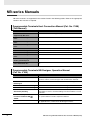


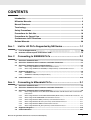


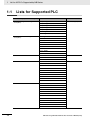
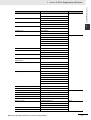
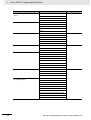


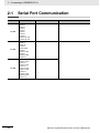
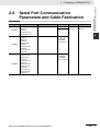
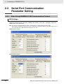
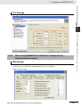
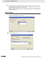
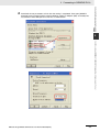
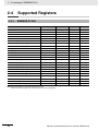

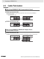
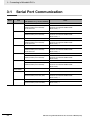
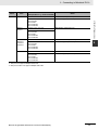
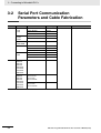
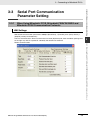
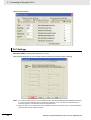
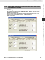
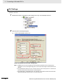
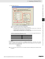

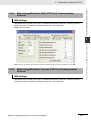
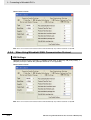
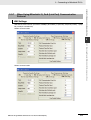
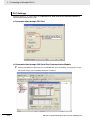

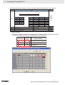


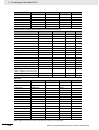
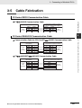
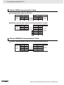

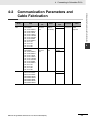
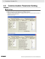
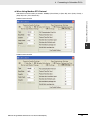

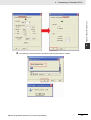
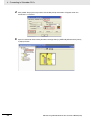
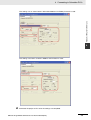
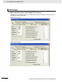
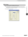
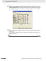
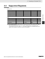
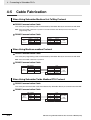

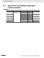
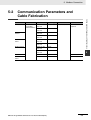
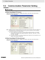
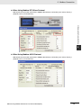
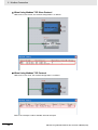
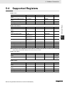
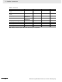
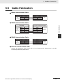
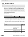
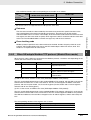
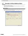
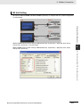
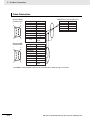
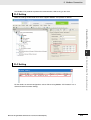

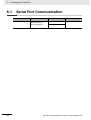
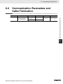
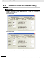
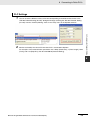
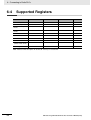
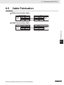


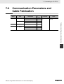
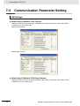
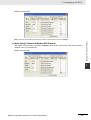
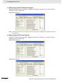
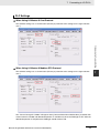
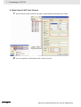
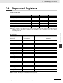

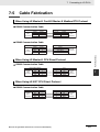
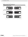
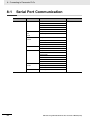
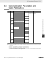
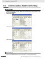
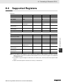
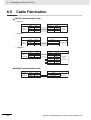
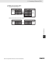

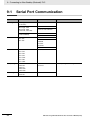
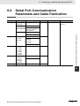

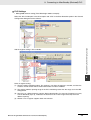

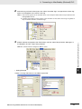
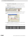
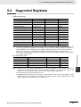
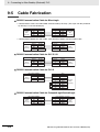
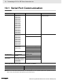
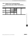
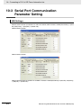
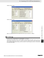
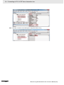
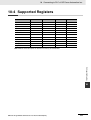
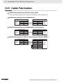
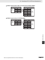


![Rockwell (Allen-Bradley) PLCs [Ethernet Communication] - Pro](http://vs1.manualzilla.com/store/data/005902559_1-37f0d35b01d224110d582dd04f222df0-150x150.png)