1
&DW1R9( 1%VHULHV 1%47:% 1%47:% 1%:7:% 1%:7:% 3URJUDPPDEOH7HUPLQDOV STARTUP GUIDE MANUAL OMRON, 2011 All rights reserved. No part of this publication may be reproduced, stored in a retrieval system, or transmitted, in any form, or by any means, mechanical, electronic, photocopying, recording, or otherwise, without the prior written permission of OMRON. No patent liability is assumed with respect to the use of the information contained herein. Moreover, because OMRON is constantly striving to improve its high-quality products, the information contained in this manual is subject to change without notice. Every precaution has been taken in the preparation of this manual. Nevertheless, OMRON assumes no responsibility for errors or omissions. Neither is any liability assumed for damages resulting from the use of the information contained in this publication. Trademarks • Sysmac and SYSMAC are trademarks or registered trademarks of OMRON Corporation in Japan and other countries for OMRON factory automation products. • Windows, Windows XP, Windows Vista, Windows 7, Windows 8, Excel are registered trademarks of Microsoft Corporation in the USA and other countries. • EtherCAT® is registered trademark and patented technology, licensed by Beckhoff Automation GmbH, Germany. • ODVA, CIP, CompoNet, DeviceNet, and EtherNet/IP are trademarks of ODVA. • The SD and SDHC logos are trademarks of SD-3C, LLC. Other company names and product names in this document are the trademarks or registered trademarks of their respective companies. NB-series NB3Q-TW B NB5Q-TW B NB7W-TW B NB10W-TW01B Programmable Terminals Startup Guide Manual Revised February 2014 Introduction Thank you for purchasing an NB-series Programmable Terminal. NB-Series Programmable Terminals (PTs) are designed to handle information generated in FA production sites. Be sure to understand the functions and performances etc thoroughly before using PT correctly. Intended Audience This manual is intended for the following personnel, who must also have knowledge of electrical systems (an electrical engineer or the equivalent). • Personnel in charge of introducing FA systems into production facilities. • Personnel in charge of designing FA systems. • Personnel in charge of installing and connecting FA facilities. • Personnel in charge of managing FA systems and facilities General Precautions • The user must operate the product according to the performance specifications described in the operation manuals. • Do not use the PT touch switch input functions for applications where danger to human life or serious property damage is possible, or for emergency switch applications. • Before using the product under conditions which are not described in the manual or applying the product to nuclear control systems, railroad systems, aviation systems, vehicles, combustion systems, medical equipment, amusement machines, safety equipment, and other systems, machines and equipment that may have a serious influence on lives and property if used improperly, consult your OMRON representative. • Make sure that the ratings and performance characteristics of the product are sufficient for the systems, machines, and equipment, and be sure to provide the systems, machines, and equipment with double safety mechanisms. • This manual provides information for connecting and setting up an NB-Series PT. Be sure to read this manual before attempting to use the PT and keep this manual close at hand for reference during installation and operation. NB-series Programmable Terminals Startup Guide Manual(V109) 1 NB-series Manuals NB-series manuals are organized in the sections listed in the following tables. Refer to the appropriate section in the manuals as required. Programmable Terminals Startup Guide Manual (Cat. No. V109) (This manual) Section Contents Section 1 NB Overview This section provide specifications of the NB Unit, describes its names and functions of the various parts. Section 2 System Design This section describes the manual structure, takes NB7W as an example to introduce the operation procedures of the NB system. Section 3 Installation and Wiring This section describes how to install and wire the NB Unit. Section 4 Screen Creation This section describes how to create a demonstration project through NB-Designer. Section 5 Run This section describes how to start running at the Host side and prepare to send screen data to NB7W. Section 6 Maintenance and Troubleshooting This section describes the maintenance and inspection methods for preventing errors occurring, and troubleshooting measures when errors occur. Programmable Terminals NB-Designer Operation Manual (Cat. No. V106) Section 2 Contents Section 1 Introduction This section provides an outline of the NB-series PTs, including their functions, features, connection types and communication methods. Section 2 Installation and Startup of NB-Designer This section describes how to install and start the NB-Designer. Section 3 Functions of NB-Designer This section describes the functions of NB-Designer. Section 4 Functions of NBManager This section describes the functions of NBManager. Section 5 Maintenance and Abnormality Handling This section describes the maintenance and check to prevent the abnormality occurrence and the handling of the abnormalities occurred in NB Unit. Section 6 Descriptions of New Functions Added into NBTW01B This section describes the new functions added into NB-TW01B, the system attributes and the component attributes. Section 7 Pictbridge Printing This section describes the Pictbridge printing function. Appendices The appendices provide lists of the NB Units, the Communication Units, the applicable PLCs, the registers supported by PLC, and the list of NBDesigner functions. NB-series Programmable Terminals Startup Guide Manual(V109) Programmable Terminals Setup Manual (Cat. No. V107) Section Contents Section 1 Part Names and Functions This section describes the names and functions of the various parts of an NB Unit. Section 2 Installing the NB Unit and Connecting Peripheral Devices This section describes the methods used to install the NB Unit and connect peripheral devices. Section 3 System Setting Mode This section describes the System Setting Mode. Section 4 Calibrate Mode This section describes the Calibrate Mode. Appendices The appendices provide information on specifications, dimensions, wirings, and lists of the NB Units, the applicable PLCs and options. Programmable Terminals Host Connection Manual (Cat. No. V108) Section Contents Section 1 List for All PLCs Supported by NB series This section lists all PLCs supported by NB Units. Section 2 Connecting to SIEMENS PLCs This section describes the connection to SIEMENS PLCs. Section 3 Connecting to Mitsubishi PLCs This section describes the connection to Mitsubishi PLCs. Section 4 Connecting to Schneider PLCs This section describes the connection to Schneider PLCs. Section 5 Modbus Connection This section describes the connection on Modbus protocol. Section 6 Connecting to Delta PLCs This section describes the connection to Delta PLCs. Section 7 Connecting to LSIS PLCs This section describes the connection to LSIS PLCs. Section 8 Connecting to Panasonic Industrial Devices SUNX PLCs This section describes the connection to Panasonic Industrial Devices SUNX PLCs. Section 9 Connecting to AllenBradley (Rockwell) PLC This section describes the connection to Allen-Bradley PLC. Section 10 Connecting to PLC of GE Fanuc Automation Inc. This section describes the connection to PLC of GE Fanuc Automation Inc. WARNING Failure to read and understand the information provided in this manual may result in personal injury or death, damage to the product, or product failure. Please read each section in its entirety and be sure you understand the information provided in the section and related sections before attempting any of the procedures or operations given. NB-series Programmable Terminals Startup Guide Manual(V109) 3 Manual Structure Page Structure and Icons The following page structure and icons are used in this manual. Level 1 heading Level 2 heading Level 3 heading 2 Installing the NB Unit and Connecting Peripheral Devices Level 3 heading 2-1-2 Installation onto the Operation Panel Use the metal kit and tool (a crosshead screwdriver) supplied with the Unit for installation. Proceed the installation following the procedures below. Step in a procedure 1 Indicates a step in a procedure. Panel cutout with dimensions is shown below. Fit the NB Unit into the panel from the front side. Width 2-1 Installing the NB Unit Install the NB Unit by embedding it into the operation panel. 2 Height Models NB3Q-TW00B/TW01B NB5Q-TW00B/TW01B 2 Opening Dimension (W H mm) 119.0(+0.5/-0) 93.0(+0.5/-0) 172.4(+0.5/-0) 131.0(+0.5/-0) NB7W-TW00B/TW01B 191.0(+0.5/-0) 137.0(+0.5/-0) NB10W-TW01B 258.0(+0.5/-0) 200.0(+0.5/-0) As follows, insert panel fixators at the locations indicated by red box around the back of the NB Unit. Insert the hooks of positioners into the square holes on the Unit to hold the fixators properly, and tighten the screws firmly with the screwdriver. 2-1-2 Installation onto the Operation Panel Opening dimensions Gives the current headings. Page tab Gives the number of the section. NB5Q/NB7W-TWB Special Information (See below.) Icons are used to indicate precautions and additional information. Precautions for Safe Use • When operating on the operation panel, make sure to keep metal particles from entering the Unit. The mounting panel must be between 1.6 and 4.8 mm thick. The NB Unit must be installed in a control panel. For the sake of waterproof and dustproof, all the fixators must be evenly tightened to a torque of 0.5~0.6 Nm. If the tightening torque exceeds the specified value, or the tightening is not even, deformation of the front panel may occur. Make sure that the operation panel is clean, unbent, and strong enough for the installation process. Manual name 2-3 NB-series Programmable Terminals Setup Manual(V107) This illustration is provided only as a sample and may not literally appear in this manual. Special Information Special information in this manual is classified as follows: Precautions for Safe Use Precautions on what to do and what not to do to ensure using the product safely. Precautions for Correct Use Precautions on what to do and what not to do to ensure proper operation and performance. Additional Information Additional information to increase understanding or make operation easier. 4 NB-series Programmable Terminals Startup Guide Manual(V109) Terminology The following terminology is used in this manual. Terms Descriptions NB Unit Indicates the main Unit of the products in the OMRON NB Series of Programmable Terminal. NB Series Indicates products in the OMRON NB Series of Programmable Terminal. In this manual, unless otherwise specified, NB Series is taken as the subject concerned. PLC Indicates a Programmable Controller. CP Series Indicates the following products in the OMRON CP Series of Programmable Controllers: CP1H, CP1L, CP1E CS/CJ Series Indicates the following products in the OMRON CS/CJ Series of Programmable Controllers: CS1G, CS1H, CS1G-H, CS1H-H, CJ1G, CJ1M, CJ2M, CJ2H NJ Series Indicates the following OMRON SYSMAC NJ Series of Programmable Controllers: NJ501, NJ301 C Series Indicates the following products in the OMRON C Series of Programmable Controllers: C200HX(-Z), C200HG(-Z), C200HE(-Z), CQM1, CQM1H, CPM1A, CPM2A, CPM2C Serial Communication Unit Indicates a Serial Communication Unit for an OMRON SYSMAC CS/CJ-Series PLC. Serial Communication Board Indicates a Serial Communication Board for an OMRON SYSMAC CS/CJ-Series PLC. Communication Board Indicates a Communication Board for an OMRON C200HX/HG/HE(-Z) PLC. CPU Unit Indicates a CPU Unit in the OMRON CP, CS/CJ or SYSMAC C Series of Programmable Controllers. NB-Designer Indicates the OMRON NB-Designer. Host Indicates the PLC and other units functioning as the control devices for NB-Series Units. PT Indicates an OMRON Programmable Terminal. NB-series Programmable Terminals Startup Guide Manual(V109) 5 6 NB-series Programmable Terminals Startup Guide Manual(V109) CONTENTS Introduction............................................................................................................... 1 NB-series Manuals.................................................................................................... 2 Manual Structure ...................................................................................................... 4 Terminology .............................................................................................................. 5 Terms and Conditions Agreement .......................................................................... 9 Safety Precautions ................................................................................................. 11 Precautions for Safe Use ....................................................................................... 14 Precautions for Correct Use .................................................................................. 16 Conformance to EC Directives .............................................................................. 17 Related Manuals ..................................................................................................... 18 Sec. 1 NB Overview........................................................................... 1-1 1-1 Models of NB Series................................................................................................................ 1-2 1-2 Part Names and Functions ..................................................................................................... 1-3 Sec. 2 System Design ....................................................................... 2-1 2-1 About this Manual ................................................................................................................... 2-2 2-2 Demonstration System ........................................................................................................... 2-3 Sec. 3 Installation and Wiring .......................................................... 3-1 3-1 Installation................................................................................................................................ 3-2 3-2 Equipment Wiring.................................................................................................................... 3-5 Sec. 4 Screen Creation ..................................................................... 4-1 4-1 Starting NB-Designer .............................................................................................................. 4-2 4-2 Main Window of NB-Designer................................................................................................. 4-3 4-3 Creating Project ....................................................................................................................... 4-5 4-4 Screen Creation ..................................................................................................................... 4-13 4-5 PT Property ............................................................................................................................ 4-27 4-6 Save and Load Project .......................................................................................................... 4-28 NB-series Programmable Terminals Startup Guide Manual(V109) 7 Sec. 5 Run .......................................................................................... 5-1 5-1 Preparations............................................................................................................................. 5-2 5-2 Run NB7W ................................................................................................................................ 5-5 Sec. 6 Maintenance and Troubleshooting....................................... 6-1 6-1 Maintenance ............................................................................................................................. 6-2 6-2 Checking and Cleaning ........................................................................................................... 6-3 6-3 Troubleshooting....................................................................................................................... 6-5 6-3-1 6-3-2 6-3-3 6-3-4 6-3-5 6-4 Countermeasures for errors ........................................................................................................ 6-5 Communication-related Troubles .............................................................................................. 6-25 Hardware Troubles .................................................................................................................... 6-29 Errors occurred when the UDP communications with OMRON PLC ........................................ 6-31 Other Troubles........................................................................................................................... 6-31 Unit Replacement Precautions............................................................................................. 6-33 Revision History ........................................................................................................ 1 8 NB-series Programmable Terminals Startup Guide Manual(V109) Terms and Conditions Agreement Warranty, Limitations of Liability Warranties z Exclusive Warranty Omron’s exclusive warranty is that the Products will be free from defects in materials and workmanship for a period of twelve months from the date of sale by Omron (or such other period expressed in writing by Omron). Omron disclaims all other warranties, express or implied. z Limitations OMRON MAKES NO WARRANTY OR REPRESENTATION, EXPRESS OR IMPLIED, ABOUT NON-INFRINGEMENT, MERCHANTABILITY OR FITNESS FOR A PARTICULAR PURPOSE OF THE PRODUCTS. BUYER ACKNOWLEDGES THAT IT ALONE HAS DETERMINED THAT THE PRODUCTS WILL SUITABLY MEET THE REQUIREMENTS OF THEIR INTENDED USE. Omron further disclaims all warranties and responsibility of any type for claims or expenses based on infringement by the Products or otherwise of any intellectual property right. z Buyer Remedy Omron’s sole obligation hereunder shall be, at Omron’s election, to (i) replace (in the form originally shipped with Buyer responsible for labor charges for removal or replacement thereof) the non-complying Product, (ii) repair the non-complying Product, or (iii) repay or credit Buyer an amount equal to the purchase price of the non-complying Product; provided that in no event shall Omron be responsible for warranty, repair, indemnity or any other claims or expenses regarding the Products unless Omron’s analysis confirms that the Products were properly handled, stored, installed and maintained and not subject to contamination, abuse, misuse or inappropriate modification. Return of any Products by Buyer must be approved in writing by Omron before shipment. Omron Companies shall not be liable for the suitability or unsuitability or the results from the use of Products in combination with any electrical or electronic components, circuits, system assemblies or any other materials or substances or environments. Any advice, recommendations or information given orally or in writing, are not to be construed as an amendment or addition to the above warranty. See http://www.omron.com/global/ or contact your Omron representative for published information. Limitation on Liability; Etc OMRON COMPANIES SHALL NOT BE LIABLE FOR SPECIAL, INDIRECT, INCIDENTAL, OR CONSEQUENTIAL DAMAGES, LOSS OF PROFITS OR PRODUCTION OR COMMERCIAL LOSS IN ANY WAY CONNECTED WITH THE PRODUCTS, WHETHER SUCH CLAIM IS BASED IN CONTRACT, WARRANTY, NEGLIGENCE OR STRICT LIABILITY. Further, in no event shall liability of Omron Companies exceed the individual price of the Product on which liability is asserted. NB-series Programmable Terminals Startup Guide Manual(V109) 9 Application Considerations Suitability of Use Omron Companies shall not be responsible for conformity with any standards, codes or regulations which apply to the combination of the Product in the Buyer's application or use of the Product. At Buyer's request, Omron will provide applicable third party certification documents identifying ratings and limitations of use which apply to the Product. This information by itself is not sufficient for a complete determination of the suitability of the Product in combination with the end product, machine, system, or other application or use. Buyer shall be solely responsible for determining appropriateness of the particular Product with respect to Buyer's application, product or system. Buyer shall take application responsibility in all cases. NEVER USE THE PRODUCT FOR AN APPLICATION INVOLVING SERIOUS RISK TO LIFE OR PROPERTY WITHOUT ENSURING THAT THE SYSTEM AS A WHOLE HAS BEEN DESIGNED TO ADDRESS THE RISKS, AND THAT THE OMRON PRODUCT(S) IS PROPERLY RATED AND INSTALLED FOR THE INTENDED USE WITHIN THE OVERALL EQUIPMENT OR SYSTEM. Programmable Products Omron Companies shall not be responsible for the user's programming of a programmable Product, or any consequence thereof. Disclaimers Performance Data Data presented in Omron Company websites, catalogs and other materials is provided as a guide for the user in determining suitability and does not constitute a warranty. It may represent the result of Omron's test conditions, and the user must correlate it to actual application requirements. Actual performance is subject to the Omron's Warranty and Limitations of Liability. Change in Specifications Product specifications and accessories may be changed at any time based on improvements and other reasons. It is our practice to change part numbers when published ratings or features are changed, or when significant construction changes are made. However, some specifications of the Product may be changed without any notice. When in doubt, special part numbers may be assigned to fix or establish key specifications for your application. Please consult with your Omron's representative at any time to confirm actual specifications of purchased Product. Errors and Omissions Information presented by Omron Companies has been checked and is believed to be accurate; however, no responsibility is assumed for clerical, typographical or proofreading errors or omissions. 10 NB-series Programmable Terminals Startup Guide Manual(V109) Safety Precautions Notation Used for Safety Information The following notation is used in this manual to provide precautions required to ensure safe usage of the product. The safety precautions that are provided are extremely important to safety. Always read and heed the information provided in all safety precautions. WARNING Indicates an imminently hazardous situation which, if not avoided, will result in death or serious injury. Additionally, there may be severe property damage. Precautions for Safe Use Indicates precautions on what to do and what not to do to ensure using the product safely. Precautions for Correct Use Indicates precautions on what to do and what not to do to ensure proper operation and performance. Note Indicates suggestive information and precautions on operation of the product. Symbols The circle and slash symbol indicates operations that you must not do. The specific operation is shown in the circle and explained in text. This example indicates prohibiting disassembly. The triangle symbol indicates precautions (including warnings). The specific operation is shown in the triangle and explained in text. This example indicates a general precaution. NB-series Programmable Terminals Startup Guide Manual(V109) 11 WARNING Do not attempt to take the product apart and do not touch the product inside while the power is being supplied. Otherwise it may result in electric shock. Always ensure that the personnel in charge confirm that installation, inspection, and maintenance were properly performed for the NB Unit. “Personnel in charge” refers to individuals qualified and responsible for ensuring safety during machine design, installation, operation, maintenance, and disposal. Ensure that installation and post-installation checks are performed by personnel in charge who possess a thorough understanding of the machinery to be installed. Do not use the input functions of the touch switch, etc. of the NB Unit, in applications that involve human life, in applications that may result in serious injury, or for emergency stop switches. Do not attempt to disassemble, repair, or modify the NB Unit. Otherwise it may impair the safety functions. Never press more than two points on the touch panel of the NB Unit at a time. Otherwise, it may activate a switch somewhere between the two points. 12 NB-series Programmable Terminals Startup Guide Manual(V109) Precaution WARNING Wiring In the case of the NB Series, when grounding the positive terminal of power supply of 24 V to the NB, do not ground functional grounding terminal at NB side. Some functions of a PC connected to the NB may cause a short circuit and the NB Unit may cause damage. • Caution: Depending on the types of PC, SG terminals of RS-232C port or USB port and contour of connector can be connected. As the contour of tool port of the NB and the functional grounding terminal are not insulated, they are connected. Therefore, connecting the PC allows GND terminal and functional grounding terminal of the NB to be connected. If the power supply of 24V to the NB is grounded positively, grounding the functional grounding terminal allows a short circuit as shown in the diagram below and may result in damage. Power Supply NB 24V PC 0V GND SG Cable SG Functional Grounding Contour Contour Grounding Grounding Do not ground the functional grounding. Test Function The Test Function is performed on PC so that a problem may occur affected by the timing or the differences with communication route. When the test function is performed, considering possible unexpected circumstances on PC, confirm that any dangerous event will not occur beforehand. NB-series Programmable Terminals Startup Guide Manual(V109) 13 Precautions for Safe Use • When unpacking the NB Units and the peripheral devices, check carefully for any external scratches or other damages. Also, shake the Units gently and check for any abnormal sound. • The NB Unit must be installed in a control panel. • The mounting panel must be between 1.6 and 4.8 mm thick. Tighten the Mounting Brackets evenly to a torque of between 0.5 and 0.6 Nxm to maintain water and dust resistance. If the tightening torque exceeds the specified value, or the tightening is not even, deformation of the front panel may occur. What is more, make sure the panel is not dirty or warped and that it is strong enough to hold the Units. • Do not let metal particles enter the Units when preparing the panel. • Do not connect an AC power supply to the DC power terminals. • Use a DC power with a slight voltage fluctuation and reinforced or double insulation, and that will provide a stable output even if the input is momentarily interrupted for 10 ms. Rated Power Supply Voltage: DC 24 V (Allowable range DC 20.4 ~ 27.6 V) • Do not perform a dielectric voltage test. • Before connecting the power supply to the NB unit, mount the cable on the terminal block. Make the connection by using terminal screws crimping on a twisted-pair cable with a crimping range of 12~26 AWG, and only 6.5 mm of insulation peel of the cable needs to be peeled off. Tighten the terminal screws at a torque of between 0.3 and 0.5 Nxm. Make sure the screws are properly tightened. Do not use the terminal block of NB3Q-TW B for other models. NB3Q-TW B has different pin definitions on the terminal block. • To prevent malfunctions caused by noise, ground the Unit correctly. • Do not touch the packaging part of the circuit board with your bare hands. Discharge any static electricity from your body before handling the board. • When using the No. 6 pin of the serial communication port COM1 connector for a voltage of DC+5V, make sure the supply equipment’s current capacity is below 250mA before using it. The DC+5V voltage output of the NB unit is +5V±5%, and the maximum current is 250mA. (The serial communication port COM1 of NB3Q-TW B is unable to output the current.) • Turn OFF the power supply before connecting or disconnecting cables. • Always keep the connector screws firmly tightened after the communication cable is connected. • The maximum tensile load for cables is 30 N. Do not apply loads greater than this. • Confirm the safety of the system before turning ON or OFF the power supply, or pressing the reset button. • The whole system may stop depending on how the power supply is turned ON or OFF. Turn ON/OFF the power supply according to the specified procedure. • Reset by pressing the reset button, or restart the power supply, once the DIP switch settings are changed. • To ensure the system’s safety, make sure to incorporate a program that can confirm the normal functionality of the NB Unit before running the system. • Start actual system application only after sufficiently checking screen data, macros and the operation of the program at the host side. • Do not press the touch panel with a force greater than 30 N. • Do not use hard or pointed objects to operate or scrub the screen, otherwise, the surface of the screen may be damaged. • Confirm the safety of the system before pressing the touch panel. • Signals from the touch switches may not be input if the touch switches are pressed consecutively at high speed. Confirm each input before proceeding to the next one. • Do not accidentally press the touch panel when the backlight is not lit or when the display does not appear. Make sure of the safety of the system before pressing the touch panel. • To use numeric input functions safely, always make maximum and minimum limit settings. • Before initializing screen data, confirm that existing data is backed up at the NB-Designer. 14 NB-series Programmable Terminals Startup Guide Manual(V109) • When changing the password with the screen, do not reset or turn OFF the power supply until writing is finished. Failure to save the password may cause the screen to fail to function. • When using an equipment monitor, confirm the safety of the system before carrying out the following operations: • Changing monitor data. • Changing operation mode. • Forced set/reset. • Changing the current value or the set value. • Do not connect a USB connector to any device that is not applicable. • When connecting the equipment with the USB HOST connector, make sure the supply equipment’s current capacity is below 150mA before using it. The DC+5V voltage output of the NB Unit is +5V±5%, and the maximum current is 150mA. • Before connecting a USB connector to a device, make sure that the device is free of damage. • Commercially available and the recommended USB HUBs are different from the general specifications of the NB Unit. The unit may not function well in an environment subject to noise, static electricity. Therefore, when using a USB HUB, employ sufficient noise and static electricity insulation measures, or install it at a site free of noise or static electricity. • While uploading or downloading screen data or system programs, do not perform the following operations that may corrupt the screen data or the system program: • Turning OFF the power supply of the NB Unit. • Pressing the PT’s reset switch. • Dispose of the Units and batteries according to local ordinances as they apply. • Do not dispose the product into a fire. Doing so may cause the damage with the battery or electronic components. • Do not apply an impact with the lithium cell, charge it, dispose it into a fire, or heat it. Doing either of them may cause an ignition or a bursting. • When exporting products with lithium primary batteries containing perchlorate at 6ppb or above to or delivering them through California, USA, the following precautionary measures have to be publicized. Perchlorate material - applicable through special processing. Refer to http://www.dtsc.ca.gov/hazardouswaste/perchlorate. NB-Series products contain lithium primary batteries. When exporting products containing this kind of batteries to or delivering them through California, USA, label all the product packages as well as the appropriate delivery packages. • Do not use benzene, paint thinner, or other volatile solvents, and do not use chemically treated cloths. • Do not dispose the Units together with general waste at waste yards. When disposing them, follow the related local ordinances or rules. • Cannot replace the backlight lamp inside the NB Unit. • Deterioration over time can cause the touch points to move. Calibrate the touch panel periodically. • Water and oil resistance will be lost if the front sheet is torn or is peeling off. Do not use the Unit, if the front sheet is torn or is peeling off. • The rubber packing will deteriorate, shrink, or harden depending on the operating environment. Inspect the rubber packing periodically. • The communication cables of the COM1 and COM2 connectors are not interchangeable. Confirm the pins of the ports before carrying out communications. (NB3Q-TW B only has COM1.) • Periodically check the installation conditions in applications where the PT is subject to contact with oil or water. • Do not perform the following operations during the communication of the USB memory: • Turning off the power supply of the NB Unit. • Pressing the Reset button on the NB Unit. • Removing the USB memory. • Do not use the USB memory in the environment subject to strong vibration. NB-series Programmable Terminals Startup Guide Manual(V109) 15 Precautions for Correct Use • Do not install the unit in any of the following locations: Locations subject to severe changes in temperature Locations subject to temperatures or humidity outside the range specified in the specifications Locations subject to condensation as the result of high humidity Locations subject to corrosive or flammable gases Locations subject to strong shock or vibration Locations outdoors subject to direct wind and rain Locations subject to strong ultraviolet light Locations subject to dust Locations subject to direct sunlight Locations subject to splashing oil or chemicals • Take appropriate and sufficient countermeasures when installing systems in the following locations: Locations subject to static electricity or other forms of noise Locations subject to strong electric field or magnetic field Locations close to power supply lines Locations subject to possible exposure to radioactivity • Precautions for software: The update, restoration, uninstall and reinstallation of software in running status is prohibited in order to guarantee the correct use of the product. 16 NB-series Programmable Terminals Startup Guide Manual(V109) Conformance to EC Directives NB-Series Programmable Terminals are EMC compliant. Concepts OMRON products are electronic devices that are incorporated in machines and manufacturing installations. OMRON PTs conform to the related EMC Directives (see note) so that the devices and machines into which they are built can more easily conform to EMC Directives. The actual products have been through inspections and are completely in accordance with EMC directives. However, when they are built into customers’ systems, whether the systems also comply with these Directives is up to the customers for further inspection. EMC-related performance of OMRON PTs will vary depending on the configuration, wiring, and other conditions of the OMRON equipment or control panel. The customer must, therefore, perform final checks to confirm that the overall machine or device conforms to EMC standards. Note The applicable EMC (Electromagnetic Compatibility) standards are as follows: EMS (Electromagnetic sensitivity): EN61131-2: 2007 EMI (Electromagnetic Interference): EN61131-2: 2007 Conformance to EC Directives NB-Series Programmable Terminals are EC compliant. Heed the following precautions in order to ensure that the customer’s overall machine and device conform to EC Directives. 1 2 3 4 The PT must be installed in a control panel. You must use reinforced insulation or double insulation for the DC power supply and the DC power supply must have minimal voltage fluctuations and provide a stable output even if the power supply input is interrupted for 10 ms. The PTs conform to the standard EN 61131-2, but radiated emission characteristics (10m regulations) may vary depending on the configuration of the control panel used, other devices connected to the control panel, wiring, and other conditions. You must therefore confirm that the overall machine or equipment complies with EC Directives. This is a Class A product (Product for industry purpose). It may cause radio interference in residential areas, in which case the user may be required to take adequate measures to reduce interference. Conformance to KC Standards Observe the following precaution if you use NB-series Programmable Terminals in Korea. Class A Device (Broadcasting Communications Device for Office Use) This device obtained EMC registration for office use (Class A), and it is intended to be used in places other than homes. Sellers and/or users need to take note of this. NB-series Programmable Terminals Startup Guide Manual(V109) 17 Related Manuals The related manuals are as follows: Devices and Software NB series PLC Manual Name Manual No. NB Series NB-Designer Operation Manual V106 NB Series Setup Manual V107 NB Series Host Connection Manual V108 NB Series Startup Guide (This manual) V109 SYSMAC CP Series CP1L CPU Unit Operation Manual W462 SYSMAC CP Series CP1H/L CPU Unit Programming Manual W451 SYSMAC CP Series CP1H CPU Unit Operation Manual W450 SYSMAC CP Series CP1E CPU Unit Hardware USER’S Manual W479 SYSMAC CP Series CP1E CPU Unit Software USER’S Manual W480 SYSMAC C200HX/HG/HE(-E/-ZE) Installation Guide W302 SYSMAC C200HX/HG/HE Operation Manual W303 SYSMAC C200HX/HG/HE(-ZE) Operation Manual W322 SYSMAC CPM1A Operation Manual W317 SYSMAC CPM2A Operation Manual W352 SYSMAC CPM1/CPM1A/CPM2A/CPM2C/SRM1(-V2) Programming Manual W353 SYSMAC CPM2C Operation Manual W356 SYSMAC CS1 Series CS1G/H Operation Manual W339 SYSMAC CS/CJ Series Serial Communications Boards and Serial Communications Units Operation Manual W336 SYSMAC CJ Series CJ1G/H(-H) CJ1M CJ1G Operation Manual W393 SYSMAC CS/CJ Series Programming Manual W394 SYSMAC CS/CJ Series INSTRUCTIONS Reference Manual W340 SYSMAC CS/CJ Series Programming Consoles Operation Manual W341 SYSMAC CS/CJ Series Communications Commands Reference Manual W342 SYSMAC CJ Series CJ2 CPU Unit Hardware USER’S Manual W472 SYSMAC CJ Series CJ2 CPU Unit Software USER’S Manual W473 SYSMAC CS/CJ Series CS1W/CJ1W-ETN21 (100Base-TX) Ethernet Units Operation Manual Construction of Networks W420 SYSMAC CS/CJ Series CS1W/CJ1W-ETN21 (100Base-TX) Ethernet Units Operation Manual Construction of Applications W421 SYSMAC CS/CJ Series CS1W/CJ1W-EIP21 (100Base-TX) EtherNet/IPTM Units Operation Manual W465 SYSMAC CP Series CP1L-EL/EM CPU Unit Operation Manual W516 18 NJ Series CPU Unit Hardware USER’S Manual W500 NJ Series CPU Unit Software USER’S Manual W501 NJ Series CPU Unit Built-in EtherNet/IPTM Port USER’S Manual W506 NJ Series Troubleshooting Manual W503 Safety Controller G9SP Series Safety Controller OPERATION MANUAL Z922 External Tool CX-Programmer Ver.9. Operation Manual W446 Sysmac Studio Version 1 Operation Manual W504 NB-series Programmable Terminals Startup Guide Manual(V109) 1 NB Overview This section provide specifications of the NB Unit, describes its names and functions of the various parts. 1-1 Models of NB Series . . . . . . . . . . . . . . . . . . . . . . . . . . . . . . . . . . . . . . . . . . . 1-2 1-2 Part Names and Functions . . . . . . . . . . . . . . . . . . . . . . . . . . . . . . . . . . . . . . 1-3 NB-series Programmable Terminals Startup Guide Manual(V109) 1-1 1 NB Overview 1-1 Models of NB Series There are 7 models of NB series PTs available now: NB3Q-TW00B/TW01B, NB5Q-TW00B/TW01B, NB7W-TW00B/TW01B and NB10W-TW01B. With TFT display used, NB series has higher cost performance. The LED backlight used is more environmentally-friendly, energy-efficient and with longer service life compared to traditional CCFL backlight. The display device of NB series (PT: Programmable Terminals) can be used for information display and receive-input operation. It can show operating states of the system and devices in graphic forms to users. z Major Parameters NB3Q Models TW00B NB5Q TW01B TW00B TW01B NB7W TW00B TW01B NB10W TW01B Performance Specifications Display Size 3.5”TFT LCD 5.6”TFT LCD 7”TFT LCD 10.1”TFT LCD Resolution QVGA 320×240 QVGA 320×234 WVGA 800×480 Display Color 65536 colors Backlight LED Memory 128M FLASH + 64M DDR2 RAM (NB -TW01B supports the USB storage) Downloading Programs USB / Serial Port / Ethernet (Only NB -TW01B supports the Ethernet downloading) Pictbridge printing By the USB Slave port (The user must use the NB-Designer of version 1.22 or later to update the kernel and file system of NB Unit when using the Pictbridge printing function for the first time. For details, refer to Section 7 Pictbridge Printing in NBDesigner Operation Manual.) USB Port Equivalent of USB 2.0 Full speed NB -TW00B: USB Slave ×1 NB -TW01B: USB Slave ×1, USB Host ×1 Communication Serial Ports Port COM1: RS-232C/ 422A/485 COM1: RS-232C COM2: RS-232C/422A/485 Network Ethernet Interface Electrical Specifications Rated Power 5W Rated Voltage DC24V 9W 6W 10W 7W 11W 14W Structural Specifications Case Color Black Dimensions W×H×D(mm) 129.8×103.8×52.8 184.0×142.0×46.0 202.0×148.0×46.0 268.8×210.8 ×54.0 Weight 300g 620g 710g 1525g 305g 627g 715g Software Tools Version No. NB-Designer Ver1.2X For download the application programs, please access your local Omron website. If local site cannot be found, please access Omron IA global site “http://www.ia.omron.com/” at first and select the area where you are. Note 1-2 NB7W is used as the abbreviated name of NB7W-TW B hereinafter. NB-series Programmable Terminals Startup Guide Manual(V109) 1 NB Overview 1-2 Part Names and Functions 1-2 Part Names and Functions This section describes the names and functions of each part of the NB Unit. z NB3Q-TW00B/NB3Q-TW01B model Front view 1 Power Indicator Display Back view : NB-TW01B only Precautions for Safe Use Confirm the safety of the system before turning ON or OFF the power supply, or pressing the reset button. NB-series Programmable Terminals Startup Guide Manual(V109) 1-3 1 NB Overview z NB5Q-TW00B/NB5Q-TW01B model Front view Power Indicator Display Back view : NB-TW01B only Precautions for Safe Use Confirm the safety of the system before turning ON or OFF the power supply, or pressing the reset button. 1-4 NB-series Programmable Terminals Startup Guide Manual(V109) 1 NB Overview 1-2 Part Names and Functions z NB7W-TW00B/NB7W-TW01B model Front view 1 Power Indicator Display Back view : NB-TW01B only Precautions for Safe Use Confirm the safety of the system before turning ON or OFF the power supply, or pressing the reset button. NB-series Programmable Terminals Startup Guide Manual(V109) 1-5 1 NB Overview z NB10W-TW01B model Front view Power Indicator Display Back view Precautions for Safe Use Confirm the safety of the system before turning ON or OFF the power supply, or pressing the reset button. 1-6 NB-series Programmable Terminals Startup Guide Manual(V109) 1 NB Overview • NB5Q/NB7W/NB10W-TW B Serial port COM1 is a 9-pin D-type socket port. This port supports RS-232C communication function, making it connectable to a controller which features RS-232C function, and it can also be used for downloading programs or debugging for the product. The pins are defined as follows: Pins Signals I/O Functions - 1 1 NC - 2 SD O 3 RD I Receiving data 4 RS(RTS) O Request to send* 5 CS(CTS) I Clear to send* 6 DC+5V - DC+5V output (Max. current: 250mA) 7 NC - - 8 NC - - 9 SG - Sending data Signal ground * Pins 4 and 5 are not used, thus not compliant with RS or CS functions. Precautions for Safe Use When using the No. 6 pin of the serial communications port COM1 connector for a voltage of DC+5V, make sure the supply equipment’s current capacity is below 250 mA before using it. The DC+5V voltage output of the NB Unit is +5V±5%, and the maximum current is 250 mA. • NB3Q-TW B NB3Q-TW B has only 1 serial port COM1, and this port supports communication (non-isolated) based on RS-232C, RS-422 and RS-485, of which only 1 connection mode can be applied at one time. By means of the RS-232C mode (PIN 2~5), it can be connected to a controller based on RS232C, and can also be used for downloading programs, as well as debugging for the product (connected to a PC). While with the RS-422 or the RS-485 mode (PIN 1, PIN 6~8), only a PLC can be connected. The pins are defined as follows: Pins Signals I/O Functions RS-232C RS-485 RS-422A - - Sending data(+) 1 SDB+ I/O 2 SD O Sending data - - 3 RD I Receiving data - - 4 RS(RTS) O Request to send* - - 5 CS(CTS) I Clear to send* - - 6 RDB+ I/O - 7 SDA- I/O - 8 RDA- I/O - 9 SG - RS485B Send/Receive data(+) RS485A Send/Receive data(-) Receiving data(+) Sending data(-) Receiving data(-) Signal ground * Pins 4 and 5 are not used, thus not compliant with RS or CS functions. NB-series Programmable Terminals Startup Guide Manual(V109) 1-2 Part Names and Functions z Serial Port COM1 1-7 1 NB Overview z Precaution for Cable Fabrication The COM 2 ports included in this manual and marked by cable manufacturers are intended for the PT of NB5Q/NB7W/NB10W-TW B models, therefore when communication connection is carried out with the COM 1 port of NB3Q-TW B, please refer to the pin definitions in this section prior to connection. z Serial Port COM2 • NB5Q/NB7W/NB10W-TW B Serial port COM2 is a 9-pin D-type socket port. This port supports RS-232C/RS-485/RS-422A communication function. The pins are defined as follows: Pins Signals Functions I/O RS-232C RS-485 RS-422A - - Sending data(+) - - - - 1 SDB+ I/O 2 SD O Sending data 3 RD I Receiving data 4 Terminal R1 - - Terminal resistor 5 Terminal R2 - - Terminal resistor 6 RDB+ I/O - Send/Receive data(+) 7 SDA- I/O - - 8 RDA- I/O - Send/Receive data(-) 9 SG - Signal ground Receiving data(+) Sending data(-) Receiving data(-) z USB HOST NB -TW01B is equipped with USB HOST port, which is USB A-type port. Through this port, USB memory can be connected to perform uploading, downloading, project operation and storage of related data. And its pins are defined as follows: Pins 1 2 3 4 Signals Functions 1 Vbus USB +5V power supply output (Max. current: 150mA) 2 D- Data - 3 D+ Data + 4 GND USB power supply ground Precautions for Safe Use When connecting the equipment with the USB HOST connector, make sure the supply equipment’s current capacity is below 150mA before using it. The DC+5V voltage output of the NB Unit is +5V±5%, and the maximum current is 150mA. 1-8 NB-series Programmable Terminals Startup Guide Manual(V109) 1 NB Overview USB SLAVE port is USB B-type port, which can connect the USB port on PC side to perform the uploading, downloading, debugging of the programs for the product and the Pictbridge printing. And its pins are defined as follows: Pins 3 4 Signals Functions 2 1 Vbus USB +5V power supply output 1 2 D- Data - 3 D+ Data + 4 GND USB power supply ground 1 z Ethernet Interface NB -TW01B is equipped with Ethernet Interface, which is adaptive RJ-45 type interface with the transmission rate of 10M / 100M. It can be connected with PC to perform the uploading and downloading of the programs and the system refreshing, and can also be used to realize the communication with the controller supporting the Ethernet communication. And its pins are defined as follows: TOP Bottom Pins 8 1 1 8 NB-series Programmable Terminals Startup Guide Manual(V109) 1-2 Part Names and Functions z USB SLAVE Signals Functions 1 TD+ Sending data + 2 TD- Sending data - 3 RD+ Receiving data + 4 --- Not used 5 --- Not used 6 RD- Receiving data - 7 --- Not used 8 --- Not used 1-9 1 NB Overview z DIP Switch NB5Q/NB7W only has 2 switches SW1 and SW2, while for the NB3Q and NB10W, there are totally 4 DIP switches, and for all models, SW1 and SW2 feature the same functions. The settings and corresponding operating modes are as follows: ON SW1 ON 1 2 SW2 Operating modes ON ON System Setting Mode OFF ON Calibrate Mode ON OFF Downloader Mode OFF OFF User Project Mode • System Setting Mode: The PT will be launched into a built-in system setup screen, and is subject to the user for the settings of brightness, system time, buzzer and Pictbridge printing function. • Calibrate Mode: When the user touches the panel, a symbol “+” will pop up on the screen, with which the touch control precision level can be calibrated. • Downloader Mode: This is used for updating Kernel and root file system. • User Project Mode: This is the User Project Mode of NB-Series PTs. The PT will display the startup screen of the project already downloaded. As mentioned above, the settings and corresponding operating modes of the switches SW1 and SW2 of NB3Q and NB10W are the same as those of NB5Q/NB7W (see the table above), and the functions of SW3 and SW4 of NB3Q and NB10W are stated as below: 4 3 Switch No. (corresponding model(s)) 2 1 ON SW3 (NB3Q) Status Descriptions of Function ON Terminal resistance ON OFF Terminal resistance OFF SW3 (NB10W) Reserved SW4 (NB3Q/NB10W) Reserved z Reset Switch When pressing the reset switch located on the back side of the PT, the system will be rebooted. 1-10 NB-series Programmable Terminals Startup Guide Manual(V109) 2 System Design This section describes the manual structure, takes NB7W as an example to introduce the operation procedures of the NB system. 2-1 About this Manual . . . . . . . . . . . . . . . . . . . . . . . . . . . . . . . . . . . . . . . . . . . . . 2-2 2-2 Demonstration System . . . . . . . . . . . . . . . . . . . . . . . . . . . . . . . . . . . . . . . . . 2-3 NB-series Programmable Terminals Startup Guide Manual(V109) 2-1 2 System Design 2-1 About this Manual This section describes the manual structure and operation procedures of the NB7W system by way of example. z Manual Structure The case of the system using the NB Series (Take NB7W as an example) is described in the following sequence in this manual: Chapter 1. NB overview, NB model and components names description Chapter 2. Introduce example, components and program applications Chapter 3. Installation and wiring Chapter 4. Screen Creation Chapter 5. Start running Chapter 6. Maintenance and troubleshooting The examples of circuit configuration, wiring and applications are used for reference only. Be sure to refer to the relevant manuals for the specifications, performance and safety of each component when configuring practical systems. 2-2 NB-series Programmable Terminals Startup Guide Manual(V109) 2 System Design 2-2 Demonstration System z Operation • The demonstration project is the system which opens/closes the garage door responding to the inputs from NB7W or the sensor installed to the garage. • The garage door opens when sensors detect headlight flashing three times per 10 seconds. b c d a a Light sensor b OPEN switch c STOP switch d CLOSE switch • The state of garage door is displayed on NB7W. The open, close or stop operations of garage door can also be controlled by related switches on display device. a a Vehicle sensor NB-series Programmable Terminals Startup Guide Manual(V109) 2-3 2-2 Demonstration System This section takes garage door control as a demonstration system. After NB-Designer is installed, the project file of this demonstration system will be shown in the Start Menu. Click [Sample Screen(NB7)] in the [Start]-[All Programs]-[OMRON]-[NB-Designer]-[Screen Data] to open the demonstration project. Please note that the demonstration project includes macro files, so it can only be edited by running as an administrator on operating systems other than XP. Run the NB-Designer as the administrator, and then open the demonstration project in the [project]-[DemoProject_NB7W] file of NB-Designer’s installation directory. 2 2 System Design • The garage door will not be closed before the CLOSE switch is pressed or the vehicle sensor is ON after being fully opened. a a [Deactivate Auto-close] button • The garage door will be closed when the sensors detect that the entire vehicle is in the garage. • If [Deactivate Auto-close] button is pressed, the garage door will not be closed even if the vehicle sensor is ON. • Please control the garage door using related switches on the display device when the vehicle is being driven out of the garage. a a Maintenance button • NB7W will display maintenance screen for checking input devices when the maintenance button is pressed. 2-4 NB-series Programmable Terminals Startup Guide Manual(V109) 2 System Design z System Components 2-2 Demonstration System The following components are used in the garage door control system: Display device • NB7W-TW B • XW2Z-200T(PT-PLC connecting cable: 2m) • XW2Z-500T(PT-PLC connecting cable: 5m) PLC • CP1E-N20D - (20-dot I/O type) Programming device and software 2 • Personal computer • USB cable (A-type connector(male) - B-type connector(female)) • NB-Designer (screen programming tool for NB series) • CX-Programmer (PLC programming tool) Input • OPEN / STOP / CLOSE switches; SW1 / SW2 / SW3 (Function Keys on the NB7W screen) • Vehicle sensor: SEN1 • Light sensor: SEN2 • Limit switch, being ON when the garage door is fully opened: LS1 • Limit switch, being ON when the garage door is fully closed: LS2 Output • The contact for activating the motor controlling the door opening: M01 • The contact for activating the motor controlling the door closing: M02 LS1 MO1 MO2 LS2 SEN2 NB-series Programmable Terminals Startup Guide Manual(V109) SW1 SW2 SW3 SEN1 2-5 2 System Design z CP1E The CP1E is an economical PLC with high performance, which can be ideally used for small-scale manufacturing machines and control systems. The CP1E-N20D - is shown below: Please refer to the SYSMAC CP series CP1E CPU Unit User Manual for details on CP1E. 2-6 NB-series Programmable Terminals Startup Guide Manual(V109) 2 System Design z Addresses allocation table Addresses Function Component Name Corresponding Screen W_bit 0.01 Automatically close (disabled) Bit Button Fully Open W_bit 0.02 Start the maintenance screen Bit Button Wait W_bit 1.00 Open Bit Button/ All Screens/Check 2 Bit Lamp W_bit 1.01 Stop Bit Button/ All Screens/Check 2 Bit Lamp W_bit 1.02 Close Bit Button/ LW.B 10.0 Texts on screen flash Bit Lamp Stop C0 Counter address Level Meter, Wait, Check 3 T0 Timer address Number Display Check 3 D0 Switch Screens PLC Control - D 11 Output Screen No. PLC Control - CIO_bit 0.03~0.06 (See the following table) Bit Lamp Check 1 2 All Screens/Check 2 Bit Lamp Number Display The I/O relays of the PLC are allocated as follows. Equipments Contactors Addresses Vehicle sensor SEN1 0.03 Light sensor SEN2 0.04 Upper limit LS LS1 0.05 Lower limit LS LS2 0.06 Motor for opening control (Rise motor) MO1 100.00 Motor for closing control (Down motor) MO2 100.01 LS1(0.05) MO1(100.00) MO2(100.01) LS2(0.06) SEN1(0.03) SEN2(0.04) NB-series Programmable Terminals Startup Guide Manual(V109) 2-2 Demonstration System Memory allocation table 2-7 2 System Design z NB7W Screen The screens below will be displayed on NB7W. (1) WAIT The screen will be displayed when the garage door is fully closed. The number of flash of headlights is indicated in the form of Level Meter. The transparent button on the upper left corner is used for switching to the maintenance screen. (2) OPEN The screen will be displayed when the motor for opening control is activated. (3) CLOSE The screen will be displayed when the motor for closing control is activated. (4) STOP The screen will be displayed when the STOP switch is pressed. 2-8 NB-series Programmable Terminals Startup Guide Manual(V109) 2 System Design (5) FULLY OPEN 2-2 Demonstration System The screen will be displayed when the garage door is fully opened. There is a button for keeping the garage door open. 2 (6) CHECK 1 This screen is used for maintenance by displaying the input states of the sensors. The screen will be displayed when the maintenance button on [1 WAIT] screen is pressed. (7) CHECK 2 This maintenance screen can check the operation through displaying the input states of Function Keys. (8) CHECK 3 The current values of the timer and counter (used for counting flash times of headlights)are displayed on this screen which is used for maintenance. NB-series Programmable Terminals Startup Guide Manual(V109) 2-9 2 System Design The screen switch flow chart is shown below. Maintenance Button ON 1.Wait 6.Check 1 Waiting Screen Button ON Headlight Status ON Open Button ON 2.Open Upper limit LS ON Next Screen Button ON Stop Button ON 5.Full Open Car enter Status ON Close Button ON 7.Check 2 Next Screen Button ON Open Button ON 4.Stop Last Screen Button ON Last Screen Button ON 8.Check 3 Waiting Screen Button ON Stop Button ON Close Button ON 3.Close Lower limit LS ON 2-10 NB-series Programmable Terminals Startup Guide Manual(V109) 2 System Design z Ladder programs Refer to the SYSMAC CP series CP1E Software Manual and SYSMAC CX-Programmer Operation Manual for details on creating ladder programs. 2-2 Demonstration System The ladder program examples are shown below. 2 NB-series Programmable Terminals Startup Guide Manual(V109) 2-11 2 System Design 2-12 NB-series Programmable Terminals Startup Guide Manual(V109) Installation and Wiring 3 This section describes how to install and wire the NB Unit. 3-1 Installation . . . . . . . . . . . . . . . . . . . . . . . . . . . . . . . . . . . . . . . . . . . . . . . . . . . 3-2 3-2 Equipment Wiring . . . . . . . . . . . . . . . . . . . . . . . . . . . . . . . . . . . . . . . . . . . . . 3-5 NB-series Programmable Terminals Startup Guide Manual(V109) 3-1 3 Installation and Wiring 3-1 Installation This section describes the installation environment of the NB Unit and how to mount the NB Unit to the control panel. When mounting the NB unit onto the operation panel, pay attention to the following precautions. WARNING Always ensure that the personnel in charge confirm that installation, inspection, and maintenance were properly performed for the NB Unit. “Personnel In charge” refers to individuals qualified and responsible for ensuring safety during machine design, installation, operation, maintenance, and disposal. Ensure that installation and post-installation checks are performed by personnel in charge who possess a thorough understanding of the machinery to be installed. Precautions for Correct Use • Do not install the Unit in any of the following locations: Locations subject to rapid changes in temperature Locations subject to temperatures or humidity outside the range specified in the specifications Locations subject to condensation as the result of high humidity Locations subject to corrosive or flammable gases Locations subject to strong shock or vibration Locations outdoors subject to direct wind and rain Locations subject to strong ultraviolet light Locations subject to dust Locations subject to direct sunlight Locations subject to splashing oil or chemicals • Take appropriate and sufficient countermeasures when the product is used in the following locations: Locations subject to static electricity or other forms of noise Locations subject to strong electric field or magnetic field Locations close to power supply lines Locations subject to possible exposure to radioactivity Precautions for Safe Use When unpacking the NB Units and the peripheral devices, check carefully for any external scratches or other damages. Also, shake the Unit gently and check for any abnormal sound. 3-2 NB-series Programmable Terminals Startup Guide Manual(V109) 3 Installation and Wiring z Mounting NB Unit to Control Panel Install the NB Unit by embedding it into the operation panel. Use the panel mounting brackets and Phillips screwdriver installation. Proceed the installation following the procedures below. 1 Panel cutout with dimensions is shown below. Fit the NB Unit into the panel from the front side. Width 3-1 Installation Opening dimensions Height 3 Models 2 Opening Dimension (W¯H mm) NB3Q-TW00B/TW01B 119.0(+0.5/-0)¯93.0(+0.5/-0) NB5Q-TW00B/TW01B 172.4(+0.5/-0)¯131.0(+0.5/-0) NB7W-TW00B/TW01B 191.0(+0.5/-0)¯137.0(+0.5/-0) NB10W-TW01B 258.0(+0.5/-0)¯200.0(+0.5/-0) As follows, insert the panel mounting brackets at the locations indicated by red box around the back of the NB Unit. Insert the hooks of positioners into the square holes on the Unit to hold the fixators properly, and tighten the screws firmly with the screwdriver. z NB5Q/NB7W-TW B NB-series Programmable Terminals Startup Guide Manual(V109) 3-3 3 Installation and Wiring z The insert positions on the body of NB3Q-TW B/NB10W-TW01B (same fixing method as above) NB3Q -TWB NB10W -TWB Precautions for Safe Use • Do not let metal particles enter the Units when preparing the panel. • The mounting panel must be between 1.6 and 4.8 mm thick. Tighten the Mounting Brackets evenly to a torque of between 0.5 and 0.6 N·m to maintain water and dust resistance. If the appropriate torque is not used or the torque does not tighten the brackets evenly, the panel may be deformed. What is more, make sure the panel is not dirty or warped and that it is strong enough to hold the Units. z Display Mode of NB Series touch panel NB Series touch panel has 2 display modes: horizontal and vertical. The display mode can be selected when dragging a PT from the Project library Window into the Configuration and Setup Window. Menu Task Bar Menu Task Bar Horizontal display 3-4 Vertical display NB-series Programmable Terminals Startup Guide Manual(V109) 3 Installation and Wiring 3-2 Equipment Wiring This section describes the wiring of the NB Unit and CP1E. Precautions for Safe Use • Do not connect an AC power supply to the DC power terminals. • Use a DC power with a slight voltage fluctuation and reinforced or double insulation, and that will provide a stable output even if the input is momentarily interrupted for 10 ms. Rated Power Supply Voltage: DC 24 V (Allowable range DC 20.4 ~ 27.6 V) 3 The connectable power supply specifications are as follows: figure out a suitable power supply specification so as to satisfy the requirement for power supply capacity. Models NB3Q-TW00B NB3Q-TW01B NB5Q-TW00B NB5Q-TW01B NB7W-TW00B NB7W-TW01B NB10W-TW01B Rated Voltage DC24V Allowable Voltage Range DC20.4V to 27.6V Power 5W 9W 6W 10W 7W 11W 14W z NB5Q/NB7W/NB10W-TW B The reverse side of NB 0V MCCB 24V DC24V z NB3Q -TW B The reverse side of NB 24V 0V MCCB DC24V NB-series Programmable Terminals Startup Guide Manual(V109) 3-2 Equipment Wiring Power Supply 3-5 3 Installation and Wiring Precautions for Safe Use • Firstly, wire the twisted power line to the terminal block, then install the terminal block to the NB Units. Use power lines with AWG#12 to #26 thick, peel the coating 6.5 mm length, followed by tightening the screw with 0.3 to 0.5N torque. Make sure the screw of the terminal block is tightened firmly. Only NB3Q-TW B has a different pin arrangement of the terminal block. Do not make use of the terminal block of NB3Q-TW B for other equipments. Grounding The NB unit has a functional earthing terminal ( ). Arrange the wiring according to the following conditions. 1 2 When a potential difference occurs between the NB Unit and the host, arrange the earthing as illustrated. If the distance is too long to realize a single-point earthing, do not ground the earthing terminal of the NB Unit. When the NB Unit, and noise source equipments such as motors and inverters, etc. are installed on the same panel, do not ground the earthing terminal of the NB unit. NB7W CP1E Precautions for Safe Use To prevent malfunctions caused by noise, ground the Unit correctly. 3-6 NB-series Programmable Terminals Startup Guide Manual(V109) 3 Installation and Wiring CP1E Wiring This section provides a brief of grounding wiring as an example. Please refer to the SYSMAC CP series CP1E CPU Unit User Manual for details on CP1E. z Power Connection and Grounding 3-2 Equipment Wiring Connect power and ground wires to terminal blocks. R S MCCB L1 L2/N COM 01 00 03 02 05 04 07 06 09 08 11 10 3 Note Tighten the AC power cable to the terminal block at a torque of between 0.3 and 0.5 N·m. Loose screws may occasionally result in fire or failure. z Connecting I/O Devices Connect I/O devices to the terminal block. Input SEN1 LS1 (0.03) (0.05) L1 L2/N COM 01 00 03 02 05 04 07 06 09 08 11 10 SEN2 LS2 (0.04) (0.06) Output MO1 L (100.00) 00 L 01 MO2 (100.01) 02 03 04 05 07 COM COM NC COM NC COM 06 NB-series Programmable Terminals Startup Guide Manual(V109) 3-7 3 Installation and Wiring Connecting NB Unit and CP1E Execute One-to-one connection between the Host (PLC) and the NB Unit. Connect CP1E and NB7W with a PT-PLC connecting cable (XW2Z-200T). NB CP1E RS-232C(15m max) Note Please use OMRON PT-PLC connecting cable. Using other cables may result in failure. Precautions for Safe Use • Always keep the connector screws firmly tightened after the communication cable is connected. • The maximum tensile load for cables is 30 N. Do not apply loads greater than this. • Always turn OFF the power supply before connecting or disconnecting cables. 3-8 NB-series Programmable Terminals Startup Guide Manual(V109) Screen Creation This section describes how to create a demonstration project through NB-Designer. 4 4-1 Starting NB-Designer . . . . . . . . . . . . . . . . . . . . . . . . . . . . . . . . . . . . . . . . . . . 4-2 4-2 Main Window of NB-Designer . . . . . . . . . . . . . . . . . . . . . . . . . . . . . . . . . . . . 4-3 4-3 Creating Project . . . . . . . . . . . . . . . . . . . . . . . . . . . . . . . . . . . . . . . . . . . . . . . 4-5 4-4 Screen Creation . . . . . . . . . . . . . . . . . . . . . . . . . . . . . . . . . . . . . . . . . . . . . . 4-13 4-5 PT Property . . . . . . . . . . . . . . . . . . . . . . . . . . . . . . . . . . . . . . . . . . . . . . . . . . 4-27 4-6 Save and Load Project . . . . . . . . . . . . . . . . . . . . . . . . . . . . . . . . . . . . . . . . . 4-28 NB-series Programmable Terminals Startup Guide Manual(V109) 4-1 4 Screen Creation 4-1 Starting NB-Designer This section describes how to start NB-Designer. NB-Designer is a programming tool (software) for creating screens displayed on the PT of NB Series. Select [Program]-[OMRON]-[NB-Designer]-[NB-Designer] from the Windows Starting Menu to start NBDesigner. The startup can also be realized by clicking the shortcut icon on the desktop. (Note: When using the NB-Designer on operating systems other than XP, run the NB-Designer as an administrator.) The main window will be displayed after starting NB-Designer completely. Note Please refer to the NB-Designer Operation Manual for details of NB-Designer, such as the operating environment, installation and operation. 4-2 NB-series Programmable Terminals Startup Guide Manual(V109) 4 Screen Creation 4-2 Main Window of NB-Designer This section describes the functions of each part of the main window of NB-Designer. a g c h d 4-2 Main Window of NB-Designer b 4 i e f (a) Title Bar Indicating the names of applications. (b) Menu Bar Classifying the functions of NB-Designer in groups. Grouping functions are indicated in the form of pull-down menu. (c) Toolbar Displaying icons for common functions. The function names will be indicated when the cursor is put on related icons. In the tool-bar, sub-tool bar includes basic functions is displayed. (d) Project Library Window The Project Library Window contains: Communication Connection, PT, PLC, Parts, Function Parts and Project Database. (e) Output Window Displaying the compilation process of a project and providing compilation error information. (f) Status Bar Displaying information such as the current cursor position, the width/height of the target object and the editing state, etc. (g) Edit Window The window is used for designing images and setting the communication method between the PT and PLC. NB-series Programmable Terminals Startup Guide Manual(V109) 4-3 4 Screen Creation (h) Project File Window The Window adopts a tree structure to show the correlations between the project-related touch panel and macro files & BMP files. (i) Project Work Space The Window displays a tree structure to show configuration of whole the project such as the PLC, the PT, and the screens. 4-4 NB-series Programmable Terminals Startup Guide Manual(V109) 4 Screen Creation 4-3 Creating Project This section describes the procedures to set parameters and creat a project effectively for NB7WTW00B by way of example. The date created through NB-Designer are regarded as “Project”. Creating New Project Project creation should be started with setting the configuration plan when using NB-Designer the first time. 4-3 Creating Project 1 Select [File]-[New] from the main menu. The [New Project] dialogue border will pop up. 4 2 Select [NB7W-TW00B] from [PT] Project Library, drag PT to the edit window after selecting it with a single-click. Select “horizontal” for PT display Mode. Note Even when the other model is used, the project can be created by the same operations. NB-series Programmable Terminals Startup Guide Manual(V109) 4-5 4 Screen Creation 3 4 4-6 Select [OMRON CP1H/L/E] from [PLC] Project Library, drag PLC to the Configuration and Setup Window after selecting it with a single-click. Select [Serial Port] from [Connector], drag it to the Configuration and Setup Window after selecting it with a single-click. NB-series Programmable Terminals Startup Guide Manual(V109) 4 Screen Creation 5 Adjust the positions of PT and PLC on the Configuration and Setup Window to connect serial communication cables to COM1 of HMI and COM0 of PLC. 4-3 Creating Project 4 Communication Setting 1 Click the project name on the Project Work Space Window and the connecting diagram of PT and PLC appears. Then double-click the PT and “PT Property” window pops up, select “COM1 Setting” page and set the communication mode to “RS232, 115200, 7, Even Parity Check, 2”. Click OK button and the settings of the communication mode of PT COM1 are completed. NB-series Programmable Terminals Startup Guide Manual(V109) 4-7 4 Screen Creation 2 To setting the PLC: In “CX-Programmer” open the project, in project workspace select [PLC Settings]. Be sure to set the communication mode of PLC [Built-in RS232C Port] to “Mode: Host Link, Baud: 115200, Format: 7,2,E”. Creating Macro This project uses Macro files to initialize the value of LW.B 10.0 to 1, thus initializing the Bit Lamp on the [Stop] screen. 1 4-8 User could establish a macro file with the icon through the menus or toolbar. NB-series Programmable Terminals Startup Guide Manual(V109) 4 Screen Creation 2 Then a macro code edit window will appear, use single right click in the “Macro Variable Table” window, select “Add Variable”, a “Macro Variable” window will open, user can define variable parameter with it. 4-3 Creating Project 4 3 After click “OK” there is a new variable added in the “Macro Variable Table” window, it can be used in macro program as a defined variable. Refer to the NB Series NB-Designer Operation Manual(V106) for the detail. Creating Vector Graphics With powerful vector graphics and bitmap libraries function in NB-Designer, users can create any graphics such as switches, lights or tubes at will. Each vector graphic or bitmap contains 256 statuses at max. Users can make the vector graphics in the system as templates, copy them into the new created vector graphics, and then add lines, boxes, words etc. for them to generate the new vector graphics. 1 Select [Draw]-[Add Graphics] from the main menu. The [New Graphics] window will appear. NB-series Programmable Terminals Startup Guide Manual(V109) 4-9 4 Screen Creation 2 3 4-10 After create a new graphics, double click to select “CTRL_BAR001.vg” in the Project File Window, select “state0” and right single click graph below and select “Copy”. Then select “Middle.vg” graphics, and copy the graphics to be copied into it. Copy the “state1” into the graphics by the same method, and then select “Rectangle” in the toolbar to draw it into the graphics. NB-series Programmable Terminals Startup Guide Manual(V109) 4 Screen Creation 4 Then make the settings in the “Shape property” dialog box to the Shape Property, as shown below: 4-3 Creating Project 4 Note Please save the project after the completing the creation of vector graphics. 5 Please create the vector graphics “Up.vg” (an upward hollow triangle) and “Down.vg” (a downward hollow triangle) referring to the above-mentioned method. Vector graphics: Up.vg NB-series Programmable Terminals Startup Guide Manual(V109) Vector graphics: Down.vg 4-11 4 Screen Creation 6 7 4-12 Create a vector graphics “Dashed.vg”: first add a light cyan rectangle into the graphics, and then make the related settings in the “Shape property” dialog box, as shown below: Create a vector graphics “BlueFrame.vg”: first add a blue hollow rectangle into the graphics, and then make the related settings in the “Shape property” dialog box, as shown below: NB-series Programmable Terminals Startup Guide Manual(V109) 4 Screen Creation 4-4 Screen Creation This part describes how to create screens displayed on NB7W. [1 Wait] [1 Wait] is the first display screen in the garage door control system. The screen will be displayed with the lower limit LS ON. Configure functions below: • Bit Button components, allocated to [Open], [Stop] and [Close] garage door operations respectively. • Bit Button component, for accessing the maintenance screen. The component turns ON when the button is pressed for 3 seconds. The whole screen is shown below. The following objects must be created and configured: a b 4 [Open] Use the vector graphic: Up.vg Address: W_bit 1.00 [Stop] Use the vector graphic: Middle.vg Address: W_bit 1.01 [Close] Use the vector graphic: Down.vg Address: W_bit 1.02 c d a Screen b Bit Button components c Texts d Level Meter component z Screen Start the following procedures after the NB7W operation is set. 1 Select [Add Screen] 4-4 Screen Creation • Level Meter component, indicating numbers of headlights flashing detected by the sensors in forms of graphics. from the toolbar. Input “Wait” at the screen name area. The initial design screen No. is 0, named “Frame0”, when user added a new frame, the screen No. start from 10 by default. Frame 1 to 9 are default frames for the system. NB-series Programmable Terminals Startup Guide Manual(V109) 4-13 4 Screen Creation User should use this method to create total 8 screens for this project, the screen No. and names are listed as below: Screen No 2 Screen Name 10 Wait 11 Open 12 Close 13 Stop 14 Fully Open 15 Check1 16 Check2 17 Check3 Double-click “Wait” Screen to open [Screen Property], select “Background Color” and set “Background Color” to “lightCyan”. z Bit Button Component 1 Bit Button component for switching to the maintenance screen The Bit Button component is placed on the upper left corner of the screen. Pressing this hiding button (Bit Button component) to switch to maintenance screen ([6 Check 1] screen). Function: Pressing the button and turn ON W_bit0.02, the display of PT will be switched to [6. check 1] by the ladder program of CP1E. The Function Key is set transparent and will not function until being pressed for 3 seconds for the purpose of avoiding being pressed accidentally. Select [Bit Button component] from [Parts], drag it to the edit window after selecting it with a single-click. The property settings are: Write Address W_bit0.02 Bit Button Types On Graphics Use the vector graphic: Dashed.vg (A vector graphic created by user, which is a light cyan rectangle) Control Setting ON Delay 3s (Security Setting) 4-14 NB-series Programmable Terminals Startup Guide Manual(V109) 4 Screen Creation 4-4 Screen Creation 4 NB-series Programmable Terminals Startup Guide Manual(V109) 4-15 4 Screen Creation 2 Bit Button component for Open/Stop/Close Function: After the component is pressed, the bits set as write address is set to ON, and then is reset. The write addresses for each component is shown in the table below. The property settings are: Component Name Open Stop Write Address W_bit 1.00 Bit Button Type Reset switch Graphics Use the vector graphic: Up.vg (A vector graphic created by user, which is an upward arrow) Close W_bit 1.01 W_bit 1.02 Use the vector graphic: Middle.vg (A vector graphic created by user, which is a square) Use the vector graphic: Down.vg (A vector graphic created by user, which is an downward arrow) z Fixed Text Select the “Text” button on the draw toolbar and set the property of fixed text. Determined by OS language. z Level Meter Component The function of the Level Meter Component is to indicate numbers of flash of headlights detected. The times of flash are related to the current value of the ladder program counter. Up to 3 times of flash can be counted when the maximum value of the Level Meter is set to “3”.Put fixed texts [1], [2] and [3] above the Level Meter as the scale to indicate times of flash. Select [Level Meter] from [Parts], drag it to the edit window after selecting it with a single-click. 4-16 NB-series Programmable Terminals Startup Guide Manual(V109) 4 Screen Creation The attribute settings are: Read Address C0 Bar Type Standard Display Direction Left Bar Shape Rectangle Frame Color Blue Pattern Color Light grey Light cyan Alarm Under Min Color Light cyan Min. / Max. Value 0/3 Alarm Under Value 0 4-4 Screen Creation Normal Color 4 [2 Open] The [2 Open] screen will be displayed when the motor for garage door opening control is activated. Configure functions below: • Fixed text indicating the garage door state. • Bit Button components, allocated to [Open], [Stop] and [Close] garage door operations respectively. NB-series Programmable Terminals Startup Guide Manual(V109) 4-17 4 Screen Creation The whole screen is shown below. The creating method is the same as that of [1 Wait]. a c b a Screen b Fixed Text c Bit Button components [3 Close] The [3 Close] screen will be displayed when the motor for garage door closing control is activated. Configure functions below: • Fixed text indicating the garage door state. • Bit Button components, allocated to [Open], [Stop] and [Close] garage door operations respectively. The whole screen is shown below. The creating method is the same as that of [1 Wait]. a c b a Screen b Fixed Text c Bit Button components [4 Stop] The [4 Stop] screen will be displayed when all the conditions below are satisfied. • The opening and closing motors are not activated. • The upper limit LS and lower limit LS are OFF. • The Maintenance button is OFF. Configure functions below: • Bit Lamp indicating the garage door state. To make the whole screen flashed to call attention. • Bit Button components, allocated to [Open], [Stop] and [Close] garage door operations respectively. 4-18 NB-series Programmable Terminals Startup Guide Manual(V109) 4 Screen Creation The whole screen is shown below. a b c The configuration of the Bit Lamp is shown below. The creating method of the Bit Button components is the same as that of [1 Wait]. 4 z Bit Lamp The Bit Lamp and a macro program are used in this project to flash the prompt information. 1 4-4 Screen Creation a Screen b Bit Lamp c Bit Button components Select [Bit Lamp] from [Parts], drag it to the edit window after selecting it with a single-click. The property settings for the Bit Lamp are: Read Address LW.B 10.0 Type Value 1 Blinking state 1, value 0 Showing state 0 Cycle 5∗100 ms Label Transport font: 0: blank 1: Shutter Stopped NB-series Programmable Terminals Startup Guide Manual(V109) 4-19 4 Screen Creation 2 Setting the value of the LW.B 10.0 to1, the Bit Lamp can be flashed. The value of LW.B 10.0 can be initialized by the macro below. (Refer to 4-3 Creating Project for the procedure to create macro file.) The project allows the initialization by the macro after the project downloading to PT. Accordingly, put a check in the option [Use Macro when loading project] in the tab [PT Extended Property] in the screen [PT Property] and set to execute “macro_0.c” which was created. (Refer to 4-5 PT Property for the setting method). 4-20 NB-series Programmable Terminals Startup Guide Manual(V109) 4 Screen Creation [5 Fully Open] The [5 Fully Open] screen will be displayed when the lower limit LS is ON. Configure functions below: • Fixed text indicating the garage door state. • Bit Button components to block the inputs from vehicle sensors to prevent the garage door from closing automatically. • Bit Button components, allocated to [Open], [Stop] and [Close] garage door operations respectively. a c b 4-4 Screen Creation The whole screen is shown below. The creating methods for fixed text and Bit Button components for [Open], [Stop] and [Close] garage door operations are the same as that of [1 Wait]. 4 a Screen b Fixed Texts c Bit Button components z Bit Button Components Function: Block inputs from vehicle sensors. W_bit0.01 turns ON and the input CIO_bit0.03 from vehicle sensors is blocked after the component is pressed. Herein, the garage door is to be closed through manual operations on Function Keys. W_bit0.01 will turn OFF when the garage door is closed and the lower limit LS turns ON. The property settings are: Write Address W_bit0.01 Bit Button Type On Label Transport font: 0: Deactivate Auto-close 1: Deactivate Auto-close Graphics Use the vector graphic: CTRL_BAR001.vg [6 Check 1] The [6 Check 1] screen will be displayed when the maintenance button on [1 WAIT] screen is pressed. Configure functions below: • Fixed text indicating the garage door state. • The Bit Lamp components activating relevant lamp when the vehicle sensor, light sensor, upper limit LS or lower limit LS turns ON. • Function Key components, buttons for switching to [1 Wait] and [7 Check 2] screens. • Bit Button components, allocated to [Open], [Stop] and [Close] garage door operations respectively. NB-series Programmable Terminals Startup Guide Manual(V109) 4-21 4 Screen Creation The whole screen is shown below. The creating methods for fixed text and Bit Button components for [Open], [Stop] and [Close] garage door operations are the same as that of [1 Wait]. a b e d c a Screen b Fixed Texts c Bit Lamp d Function Keys e Bit Button components z Bit Lamp Components The states of the vehicle sensor, light sensor, upper LS and lower LS are shown by the lamp. The property settings for the Bit Lamp are: Corresponding Name Vehicle Sensor Read Address CIO_bit0.03 Type Normal Light Sensor CIO_bit0.04 Upper LS CIO_bit0.05 Label Do not use Graphics Use the vector graphic: Lamp2State1-00.vg Lower LS CIO_bit0.06 z Function Key Components These are used for switching to [1 Wait] and [7 Check 2] screens. The property settings of the Function Key components are: Screen Name Wait Screen Next Screen Function Key Change screen [1 Wait] Change screen [7 Check 2] Label Transport font: 0: Wait Screen 1: Wait Screen Transport font: 0: Next Screen 1: Next Screen Graphics Use the vector graphic: CTRL_BAR001.vg [7 Check 2] The [7 Check 2] screen will appear after the screen-switching button on [6 Check 1] or [8 Check 3] screen is pressed. Configure functions below: • Fixed text indicating the garage door state. • Bit Lamp components activating relevant lamp to check operations when the [OPEN], [STOP] or [CLOSE] Function Key turns ON. • Function Key component, a button for switching to [6 Check 1] and [8 Check 3] screens. • Bit Button components, allocated to [Open], [Stop] and [Close] garage door operations respectively. 4-22 NB-series Programmable Terminals Startup Guide Manual(V109) 4 Screen Creation The whole screen is shown below. The creating methods for fixed text and Bit Button components for [Open], [Stop] and [Close] garage door operations are the same as that of [1 Wait]. a b e 4-4 Screen Creation d c a Screen b Fixed Texts c Bit Lamp d Function Keys e Bit Button components z Bit Lamp Components 4 The states of the [OPEN], [STOP] and [CLOSE] switches are shown by the lamp. The property settings for Bit Lamp are: Corresponding Name OPEN Switch STOP Switch CLOSE Switch Read Address W_bit 1.00 W_bit 1.01 W_bit 1.02 Function Normal Label Transport font: 0: blank 1: OPEN Transport font: 0: blank 1: STOP Transport font: 0: blank 1: CLOSE Graphics Use the vector graphic: Lamp2State1-00.vg z Function Key Components These are used for switching to [6 Check 1] and [8 Check 3] screens. The property settings for the Function Key components are: Screen Name Previous Screen Next Screen Function Key Change Screen[6 Check 1] Change Screen[8 Check 3] Label Transport font: 0: Previous Screen 1: Previous Screen Transport font: 0: Next Screen 1: Next Screen Graphics Use the vector graphic: CTRL_BAR001.vg [8 Check 3] The [8 Check 3] screen will be displayed when the screen-switching button on the [7 Check 2] screen is pressed. Configure functions below: • Fixed text indicating the garage door state. • Number Display components displaying the current values of TIM0 and CNT0 used in the ladder program. • Function Key components, buttons for switching to [7 Check 2] and [1 Wait] screens. • Bit Button components, allocated to [Open], [Stop] and [Close] garage door operations respectively. NB-series Programmable Terminals Startup Guide Manual(V109) 4-23 4 Screen Creation The whole screen is shown below. The creating methods for fixed text and Bit Button components for [Open], [Stop] and [Close] garage door operations are the same as that of [1 Wait]. a b e d c a Screen b Fixed Texts c Number Display components d Function Keys e Bit Button components z Number Display Components The current values of TIM0 and CNT0 on the ladder program. The property settings for the Number Display are: Corresponding Name TIM0 CNT0 Read Address T0 C0 Storage Format Unsigned int Unsigned int Graphics Use the vector graphic: BlueFrame.vg (A vector graphic consists of a Number Display component and a blue border.) z Function Key Components These are used for switching to [1 Wait] and [7 Check 2] screens. The property settings for the Function Key components are: Screen Name 4-24 Previous Screen Wait Screen Function Key Change Screen[7 Check 2] Change Screen[1 Wait] Label Transport font: 0: Previous Screen 1: Previous Screen Transport font: 0: Wait Screen 1: Wait Screen Graphics Use the vector graphic: CTRL_BAR001.vg NB-series Programmable Terminals Startup Guide Manual(V109) 4 Screen Creation PLC Control Setting In this project, the screen is controlled by PLC, to realize this function, the PLC Control component should be used. Using of PLC Control component allows to change screen from the PLC or to write a number of Current Base Screen to the PLC . When Switch Screens is used, the default Word Length of the specified memory is set to 2. When a value which is corresponds to the number of the Current Base Screen is set, the screen is automatically changed to a screen which corresponds to the number. In this example, the value D 0 is used as the corresponding screen number and the number of the Current Base Screen indicated at D 11 is output. 4-4 Screen Creation z Switch Screens Select [PLC Control] from [Project Database]. 4 After clicking the Add button, make the settings in the PLC Control dialog box as shown below. NB-series Programmable Terminals Startup Guide Manual(V109) 4-25 4 Screen Creation After click [OK], there is a new event added in the list. z Write Data to PLC (Current Base Screen) Add a control event which outputs the number of Current Base Screen from the PT to the PLC in the same procedure. Then the PLC control setting has been done. Refer to the NB Series NB-Designer Operation Manual (V106) for the details on PLC Control. 4-26 NB-series Programmable Terminals Startup Guide Manual(V109) 4 Screen Creation 4-5 PT Property 1 Select “Task Bar” page on “PT Property” window and in this project example, the “Display Task Bar” is not checked. Click OK button to save the settings. 4-5 PT Property 4 2 Select “PT Extended Property” page in “PT Property” window and in this project example, the “Use Macro when loading project” item is selected and the “Initial Screen” is set to “[10 Wait] screen”. Click OK button to save the settings. The default “Initial Screen” is “0: Frame0” when PT has not created a screen. The serial number and name of the screen will appear in the pull-down menu of “Initial Screen” after the user establishes the screen. NB-series Programmable Terminals Startup Guide Manual(V109) 4-27 4 Screen Creation 4-6 Save and Load Project This part describes how to save and open data created. It also provides a brief for test function of creating screen. z Save Project 1 2 4-28 Select [File]-[Save As] from the main menu. The [Project Save Path] dialogue border will pop up. Designate [Save File] location and input the file name. Click OK. The NB-Designer project file is saved. NB-series Programmable Terminals Startup Guide Manual(V109) 4 Screen Creation z Open Projects 1 Select [File]-[Open] from the main menu. The [Open] dialogue border will pop up. 4-6 Save and Load Project 2 Designate the [Look in] location and select the file name. Single-click [Open]. Open the NBDesigner project file. NB-series Programmable Terminals Startup Guide Manual(V109) 4-29 4 4 Screen Creation z Test function The display effect of the created screen can be checked by the NB-Designer itself through the offline test without need to connect it to the PLC. Select [Tools] - [Compile] from the main menu. After the successful compilation, select [Tools] - [Offline Test] and then right-click the mouse to select “close” to exit from the test. Please note that it needs to be recompiled and then tested each time when the setting or project is changed. The offline test is convenient for users to preview the screen effect visually without need to download programs to the PT, thus enhancing the efficient programming substantially, but the offline test can only show the display effect of the project screen. Because this project involves the data sampling and input/output control of PLC, the actual operating effect can be seen only after the edited project being downloaded into PT for operation and the communication with PLC being established. If the user just wants to see the created screen effect, it needs to place one Number Input component in the Common Screen with the address of LW0 (for example), and then add the same address into the PLC Control component with the Control Type of “Switch Screens” in the PLC Control dialog box. In this case, each created screen can be seen after the number of 10 to 17 input into the Number Input component during the offline test. Later, it just needs to delete the Number Input component and the added control conditions after the correct confirmation. Refer to the NB Series NB-Designer Operation Manual (V106) for the details of the test. 4-30 NB-series Programmable Terminals Startup Guide Manual(V109) Run This section describes how to start running at the Host side and transfer screen data to NB7W. 5-1 Preparations . . . . . . . . . . . . . . . . . . . . . . . . . . . . . . . . . . . . . . . . . . . . . . . . . . 5-2 5-2 Run NB7W . . . . . . . . . . . . . . . . . . . . . . . . . . . . . . . . . . . . . . . . . . . . . . . . . . . . 5-5 NB-series Programmable Terminals Startup Guide Manual(V109) 5-1 5 5 Run 5-1 Preparations This part describes how to start running at the Host side (CP1E) and tranfer screen data to NB7W. Connect CP1E and PC Use a USB cable to connect CP1E and a PC. a c b a. PC b. USB Cable c. CP1E Note USB driver is needed to be installed when CP1E is connected to a PC the first time. Refer to the SYSMAC CP series CP1E CPU Unit Operation Manual for details on installing USB driver. Connect CP1E CX-Programmer is a programming tool [software] for creating ladder programs executed by CP1E. Aside from the programming function, it also provides functions for setting and operating CP1E, such as debugging program, indication of current values, monitoring function, PLC settings and remote programming and monitoring through the internet, etc. Please refer to the SYSMAC CX-Programmer Operation Manual for details on CX-Programmer. Run CP1E after sending programs to CP1E. Create CP1E programs using CX-Programmer. 5-2 1 Start CX-Programmer and open the created program. 2 Select [PLC]-[Work Online] from the main menu of CX-Programmer. NB-series Programmable Terminals Startup Guide Manual(V109) 5 Run Select [PLC] - [Transfer] - [To PLC] from the main menu. 4 Send data according to the procedures described on the screen. 5 5-1 Preparations 3 Select [PLC]-[Operating Mode]-[Run] from the main menu. CP1E starts running. 5 Connect NB7W and PC z Using a USB cable to connect NB7W and a PC The screen programs created by NB-Designer can be sent to NB7W. Note • It is allowed to use USB cables of any standards. • Use a USB cable with a maximum length of 5 m. NB-series Programmable Terminals Startup Guide Manual(V109) 5-3 5 Run Note USB driver for NB Series must be installed in the PC if USB is used to connect NB7W and the PC. The USB driver should be installed automatically when NB-Designer is run on a PC the first time. Refer to the NB Series NB-Designer Operation Manual (V106) for the details of USB driver installation. z Using Ethernet to connect NB7W (NB -TW01B supporting Ethernet connection) with PC Ethernet Cable 1 2 3 4 5 6 Make Network Setting in the [PT] tab in [PT Property] dialog box of NB-Designer. (e.g. IP is 192.168.250.1; Subnet Mask is 255.255.255.0 and Default Gateway is 0.0.0.0.) Set the DIP Switch of this PT to “1 ON” and “2 ON”, and then make the Network Setting: IP, Port, Subnet Mask and Gateway (Network Setting also available for the PT with Ethernet interface). Make the Network Setting in this mode same as that in the PT tab of NB-Designer. (e.g. IP is 192.168.250.1 and Subnet Mask is 255.255.255.0.) Restart the PT, and then check if the IP and Subnet Mask are set successfully. Set the IP address of PC and that of PT locating in the same network segment with the first 3 parts being same and the last part being different (e.g. IP is 192.168.250.2 and Subnet Mask is 255.255.255.0.). Use the network cable to connect PT and PC, and then the project can be downloaded immediately. Note For the details of Ethernet connection, refer to NB-Designer Operation Manual. 5-4 NB-series Programmable Terminals Startup Guide Manual(V109) 5 Run 5-2 Run NB7W This part describes how to send screen programs of NB-Designer to NB7W . 1 Connect NB7W and a PC. 2 Start NB-Designer and open the screen program created. 3 Select [Tools]-[Compile] from the main menu. Select [Tools]-[Download] after compilation is completed. 5-2 Run NB7W 5 4 NB7W restarts after data sending is completed. NB-series Programmable Terminals Startup Guide Manual(V109) 5-5 5 Run Note When downloading the project to USB memory to operate, refer to the NB Series Setup Manual (V107). In this case, the exemplary project of garage door control system will work normally after the programs are transferred to CP1E successfully by CX-Programmer and the project are downloaded into HMI successfully by NB-Designer, as well as the NB Unit are connected to CP1E and the other devices according to the requirements. 5-6 NB-series Programmable Terminals Startup Guide Manual(V109) Maintenance and Troubleshooting This section describes the maintenance and inspection methods for preventing errors occurring, and troubleshooting measures when errors occur. 6-1 Maintenance . . . . . . . . . . . . . . . . . . . . . . . . . . . . . . . . . . . . . . . . . . . . . . . . . . 6-2 6-2 Checking and Cleaning . . . . . . . . . . . . . . . . . . . . . . . . . . . . . . . . . . . . . . . . . 6-3 6-3 Troubleshooting . . . . . . . . . . . . . . . . . . . . . . . . . . . . . . . . . . . . . . . . . . . . . . . 6-5 6-3-1 Countermeasures for errors . . . . . . . . . . . . . . . . . . . . . . . . . . . . . . . . . . . . . . . 6-5 6-3-2 6-3-3 6-3-4 Communication-related Troubles . . . . . . . . . . . . . . . . . . . . . . . . . . . . . . . . . . 6-25 Hardware Troubles . . . . . . . . . . . . . . . . . . . . . . . . . . . . . . . . . . . . . . . . . . . . . 6-29 Errors occurred when the UDP communications with OMRON PLC . . . . . . . 6-31 6-3-5 Other Troubles . . . . . . . . . . . . . . . . . . . . . . . . . . . . . . . . . . . . . . . . . . . . . . . . 6-31 6-4 Unit Replacement Precautions . . . . . . . . . . . . . . . . . . . . . . . . . . . . . . . . . . 6-33 NB-series Programmable Terminals Startup Guide Manual(V109) 6-1 6 6 Maintenance and Troubleshooting 6-1 Maintenance This section describes the maintenance methods for preventing errors occurring. Maintain the PT to keep it in its optimal condition. WARNING Do not attempt to disassemble the units or touch inside of the units while the power is ON. Otherwise it may result in electric shock. Always the personnel in charge confirm that installation, inspection, and maintenance were properly performed for the NB Units. “Personnel in charge” is qualified and responsible for obtaining safety in each phase of machine design, installation, operation, maintenance, and disposal. Do not attempt to disassemble, repair, or remodel the NB units. Otherwise it may impair the proper safety functions. z Backup of application When the unit needs to be repaired due to the occurrence of some faults or to be replaced by the substitute, be sure to make backup of the applications and keep it in a safe location. z Spare part of Unit It is recommended to prepare the spare part of NB Unit in advance in order to repair the system when the faults occurred in NB Unit or the screen is not clear due to the backlight life expires. z Replace of battery The lithium battery is used for the backup of the non-screen data such as calendar data, clock data etc. The life of the battery is approximate 5 years at 25 °C (1 year = 365 days ×12 hours /day). If the battery is used at high temperature, its life will be reduced. Ask for repairment after backup the project data according to the environment in which you are using the NB units. 6-2 NB-series Programmable Terminals Startup Guide Manual(V109) 6 Maintenance and Troubleshooting 6-2 Checking and Cleaning This section describes the inspection and cleaning method for the NB Unit. Please clean and check the NB Series periodically to ensure the NB Series always in the optimal status. z Cleaning method If the display part is dirty, then the screen will hard to see. Please perform cleaning periodically according to the following points: • During the daily cleaning, please use the dry soft cloth. But if use the dry soft cloth to clean forcefully when it is too dirty, the front panel may be damaged. In this case, use the wet cloth to clean it in advance. • Waste, ethylene products or tape sticking to the Unit for a long period will generate dirt. If there is dirt sticking to the Unit, please remove it during the cleaning. Precautions for Safe Use Do not use volatile solvents such as benzine or paint thinner, or chemical cloth. 6-2 Checking and Cleaning • When the dirt cannot be cleaned by dry cleaning, please dip the cloth into the diluted neutral washing agents (concentration of 2%) completely first, and then perform cleaning after the wet cloth is wringed out. 6 z Checking method Please perform checking once every 6 months to 1 year. But the frequent checking should be necessary when the Unit is used in the extreme environments such as the environment with high temperature, high humidity or more dust etc. z Checking items Please check the following items for the criterion. If the item does not conform to the criterion, please improve the surrounding environment, retighten the screw etc. to make it conform to the criterion. Checking Items Supply voltage Checking Contents Voltage fluctuation at power terminal Criterion Allowable voltage fluctuation range Checking Method Multimeter (DC24V, -15% to +15%) Surrounding environment state Ambient temperature (temperature inside operation panel) 0~50 °C Thermometer Ambient humidity (humidity inside operation panel) 10%~90% RH(without condensation) Hygrometer Dirt Without dirt Visual check Oil mist sticking No oil penetrating into the space between the front panel and Unit box Visual check NB-series Programmable Terminals Startup Guide Manual(V109) 6-3 6 Maintenance and Troubleshooting Checking Items Installation state Object with expected life Checking Contents Criterion Checking Method Looseness of fixing metal pieces etc. Specified torque Phillips screwdrivers Connection state of connector for the cable Inserted fully and without looseness. Phillips screwdrivers Looseness of screw for external wiring Without looseness Phillips screwdrivers State of external connection cable Without abnormality such as disconnection etc. Visual check + multimeter Backlight brightness With enough brightness Backlight life: approx. 50,000 hours (Typ) at room temperature (25 °C) with 40% brightness. Visual check Battery 5 years (at 25 °C) NB local time Precautions for Safe Use • Cannot replace the backlight lamp or rubber packing inside the NB Unit. • Deterioration over time can cause the touch points to move. Calibrate the touch panel periodically. • Water and oil resistance will be lost if the front sheet is torn or is peeling off. Do not use the Unit, if the front sheet is torn or is peeling off. • Dispose of the Units and batteries according to local ordinances as they apply. • Periodically check the installation conditions in applications where the PT is subject to contact with oil or water. • The rubber packing will deteriorate, shrink, or harden depending on the operating environment. Inspect the rubber packing periodically. • To replace the battery, the NB units are also necessary to replace. Although it is restricted to NB10W-01B, the battery replacement is available to be dealt as a repairment. 6-4 NB-series Programmable Terminals Startup Guide Manual(V109) 6 Maintenance and Troubleshooting 6-3 Troubleshooting This section describes troubleshooting measures when errors occur. When a problem occurs during operation, refer to the listed problems below for the corresponding solutions. 6-3-1 Countermeasures for errors 1 How to change system parameters like user level passwords and Baud rate These are all controlled by the local special register. These system parameters can be found by double-clicking the component attributes, and selecting [System Memory]. 6-3 Troubleshooting 2 The condition of the USB driver for the HMI If PT cannot perform download/upload normally it’s usually because the USB driver is not set up properly. Setup Method: During the process of the software setup, the PC will automatically prompt you to set up the USB driver. Select an appropriate procedure to install according to the displayed information to complete the USB driver installation. However, if the automatic setup fails, you can still perform the setup manually. Connect the Unit and the PC with a USB cable, energize the Unit, and a prompt to set up new hardware will pop up at the right bottom corner. Following the displayed information, choose [Install from a list specific location (Advanced)], and find the USB driver in the driver file of NB-Designer’s installation directory. 6 6-3-1 Countermeasures for errors NB-series Programmable Terminals Startup Guide Manual(V109) 6-5 6 Maintenance and Troubleshooting For example, the addresses for changing the password online are provided below: LW10022~10023 Password for safety level 0, Retentive 2 words LW10024~10025 Passowrd for safety level 1, Retentive 2 words LW10026~10027 Password for safety level 2, Retentive 2 words LW10118~10143 Password for safety level 3~15, Retentive 2 words * 13. If the level 2 password needs to be changed, set in the software as follows: First, place a Number Input component on window, check [System Memory], then select LW10026, as shown below Select [Password] for the Data Type in the attributes page of [Numeric Data], as follows: The process is the same for changing other system parameters online. But note that after changing the following system parameters, the PT needs to be rebooted to validate the changes. System Parameter Setting: the following addresses will take effect after reboot. Addresses 6-6 Descriptions comments 10010 Initial Screen number 0~65535 10011 Screen saver (backlight saver) 0 (OFF, Constant, Screen saver inactivated) 1~600 minutes (activated) 10013 Common Sheet/Pop-up Screen 0: Normal 1: Higher than other screens 10014 Common Sheet/attribute 0: Lower than the Base screen 1: Higher than the Base screen 10015 Storage event number 0~65535 10016 RTC source 0: PLC(Local Word) 1: Internal RTC 10017 Default language 0~3 10018 System reserve HMI internal use NB-series Programmable Terminals Startup Guide Manual(V109) 6 Maintenance and Troubleshooting 3 4 6 What if the uploading password or the online change password of the PT is lost If the uploading password of PT is lost, data cannot be uploaded, and the only solution is to download the project again to overwrite the original one. Similarly, if the online change password is lost, it also requires to download the project again and set a new password. Thus, in order to guarantee the safety of users’ projects, please back up the original projects, for decryption is not within our service range. Why cannot the system time be changed during offline test Offline test uses the PC’s clock, therefore the time cannot be changed. It can only be changed when downloaded to the PT. How to use the Confirm Operation function When the user is fabricating a screen, some buttons may require a second confirmation to validate the operation, and at this time, the Confirm Operation function can fit well here. This function can control components. For example, you can check the [Confirm Operation] on the [Control Setting] attributes page of the bit status setting component, as shown below: 6-3 Troubleshooting 5 The difference between User permissions and User levels User levels: There is a difference between high-level users and low-level users: the high-level users can access to the screens which are set to the high-level, while the low-level users cannot access to the screens which are set to the high-level. Each screen is encrypted based on the user level. User permissions: The permissions are not restricted for each user level. If user name and password are entered correctly, the user can operate components which are restricted its access. The user permissions allow the user to add or delete user accounts. The user permissions can be set to the components, however, they are invalid to a password which is set to the screen. 6 6-3-1 Countermeasures for errors A dialog box as follows will pop up everytime you operate the components once this option is checked: NB-series Programmable Terminals Startup Guide Manual(V109) 6-7 6 Maintenance and Troubleshooting 7 When opening a project, what if there is a prompt: [Font not existing in the system] For example: if attempting to open a project involving in a PC that does not incorporate , a prompt “[SimHei] does not exist” will pop up, as follows: If this font issue is ignored, UnBatang. 8 6-8 will be replaced with a font that exists in the system, eg. How to set the addresses of the component for displaying Alarm and Event, and how to inquire Alarm and Event It’s best to use the internal register of the PT - LW for the address type of the component for displaying Alarm and Event, and the address can be designated as any of the vacant address in the project. When we record Alarm and Event on PT, one page is almost certainly not enough, then turn-page inquiring is needed to be set, thus the address in the properties of the component for displaying Alarm and Event takes effect. Take LW10 for an example, as follows: NB-series Programmable Terminals Startup Guide Manual(V109) 6 Maintenance and Troubleshooting Use two Command Button as the Page Up/Down button, designate the button address the same as the component for display, and set as follows in the properties page of Command Button. 9 NB-series Programmable Terminals Startup Guide Manual(V109) 6-9 6 6-3-1 Countermeasures for errors Why is there one event inquiring record less When the customer set the Page Up/Down Switching for [Command Button component], the lower limit is set to 1, which will cause the records to be one less. The correct setting is as follows: 6-3 Troubleshooting Note Incremental upper limit is set as the number of events which you need to record, while the decremental lower limit is recommended to be set to 0. 6 Maintenance and Troubleshooting 10 How to keep the time in the event record and in the PLC synchronized Check [Use External Clock] in [PT Property] __ [PT Extended Property], as follows: Meanwhile, clock register data inside the PLC is also needed to be transmitted to the local register LW9010-9017. Refer to the NB Series NB-Designer Operation Manual(V106) for the details. 11 Why cannot the history events be saved even if “saving” is selected In most of this kind of cases, although the customer selects to save them, the No. of events to be saved which is 0 by default is not changed to the No. the customer needs, thus the problem occurs. In this case, just set the No. of events to be saved to make it work. This is done in [PT Property] --- [Event History Setting], as follows: 6-10 NB-series Programmable Terminals Startup Guide Manual(V109) 6 Maintenance and Troubleshooting 12 The cause of PT prompting “RTC Device error” and the solution When PT prompt “RTC Device error”, it’s probably because the clock chip fails. If the recipe component or the system time is not used, this notice can be shielded without affecting other operations. The method to shield it is: place a [Bit Button Component] in the project’s common sheet, with the address set to LW.B 9298.0 and the set type to [Set On when Screen Open] status. 13 What if there is one digit less when displaying negative numbers, or it displays “****” When the data type in the software is decimal, the minus sign also occupies a bit, therefore one more integer bit is needed. 14 When switching the screens with PLC control, why cannot the screen being set up be accessed 15 When calling a screen with a direct screen, why does not the target screen show up completely When calling a target screen with a direct screen, the left top corner is taken as the base point. If the size of the direct screen component is smaller than then target screen, the display may be incomplete. Therefore, when editing the target screen, place the component with the left top corner as the base point and make sure that the size of the target screen is the same as that of the direct screen component. offline test still works as normal It may be caused by communication disruption between the PT and the slave. If the communication fails and the component on the screen takes the slave’s address, components like the indicator and buttons will not show up properly. Restoring the communication will solve this problem. With respect to how to restore the disrupted communication, refer to communication-related issues in this manual. 17 Can the PT be restarted without interrupting the power supply There are two ways to restart it without interrupting the power supply: Method 1: Press the RESET button on the back of the panel to restart it. Method 2: Make a [Bit Switch] component, with the address as LB9045. When LB9045=1, the PT will restart. NB-series Programmable Terminals Startup Guide Manual(V109) 6-11 6 6-3-1 Countermeasures for errors 16 Components on the screen such as the indicator, button etc. will not show up properly, while 6-3 Troubleshooting repeatedly It's likely because the value of the PLC address through which screen switching is set does not change. The screen should be switched with the PLC control, but if switching the screen with the procedure such as screen switching (not by the PLC control), as the value of the PLC address does not change, the screen cannot be accessed repeatedly with PLC control. Solution: add a [Command Button component] to the screen of leaving designated screen, with the address set to the same as the one in [PLC Control Switch Screens], and the property to [Set at Screen Close] (This value can be set as a negative). 6 Maintenance and Troubleshooting 18 How to make the PT’s buzzer sound when a alarm occurs Set Buzzer Warning in the alarm settings, and the buzzing time can be set as required, as shown below: 19 Turn the PT backlight ON with the PLC control Select the PLC control component, then select [Backlight Open], as shown below: 6-12 NB-series Programmable Terminals Startup Guide Manual(V109) 6 Maintenance and Troubleshooting 6-3 Troubleshooting 6 This may be because the text input Component or the Note Book Component involves vector fonts. When inputting Chinese characters, the text input Component and the Note Book Component do not support vector font, but only support Dot Matrix Font, as shown below: 21 How to skip to the target screen after inputting the password correctly Place a “Function Key” Component on the screen, and overlay it with a “Touch Trigger” component. Assume that the device address of the “Touch Trigger” Component is LB10 and the Trigger Type of it is OFFÆON, then select “Trigger Register” in the control settings of the attributes of the Number Input Component for password input. Setting the property to “Notice After Written” allows the LB10 to be turned ON. After Written. When the password is input correctly, it can directly skip to the screen switched by the Function Key. Note The function of the “Touch Trigger” Component is equivalent to clicking the area covered by the “Touch Trigger”. When the trigger condition is satisfied, the components in this area will be executed. NB-series Programmable Terminals Startup Guide Manual(V109) 6-13 6-3-1 Countermeasures for errors 20 Why does the character input as text turn up as messy codes 6 Maintenance and Troubleshooting 22 What if a “warning: no newline at end of file” pop up when compiling a macro program When compiling a program, a macro instruction compiling warning “warning: no newline at end of file” pops up on the Output window. No error is found after check, but the warning persists after compiling. In this situation, input an enter at the last row of the macro instruction, as follows: 23 Why does a “System Crash: SegV” appear after calling a macro program The likely causes are as follows: (a) The address range specified in the macro instruction exceeds the actual address (b) When using array data, the array data range exceeds limits. For example: when defining int array [10], if array [10] is used, there will be an issue of array exceeding limits. (c) When proceeding division operation, the denominator is 0, and no judgment is made. (d) An endless loop forms in the macro. 24 Why cannot the project filename be edited after renaming it by the Explorer The project file names cannot be changed directly, and the only way to rename a project is to use the [Save As] option in the [File] menu. 25 How to achieve indirect addressing with an index register The function of the index register: realizing the indirect addressing mode of the register. The component’s new input/output address = its original input/output address + the word address of the index register. 6-14 NB-series Programmable Terminals Startup Guide Manual(V109) 6 Maintenance and Troubleshooting After checking [Use index], click the arrow and a window as follow will turn up. 6-3 Troubleshooting 26 How to make sure that pictures imported are not distorted Cut the picture with a drawing tool first. For example, if a 320*240 picture is to be fitted on a screen with a resolution of 800*480, use Image Software to set the width at 320 and the height at 240 in EditÆResize, then import it into the configuration project, as shown below. 6 6-3-1 Countermeasures for errors NB-series Programmable Terminals Startup Guide Manual(V109) 6-15 6 Maintenance and Troubleshooting 27 When a new project is created, what roles do the screens pre-existed in the system play respectively, and can they be deleted It’s better not to delete or alter the screens pre-existed in the system, especially for new users, because each screen plays a specific role. The indications of the screen are as follows: Screen 0: default Startup Screen (Frame 0), which can be used for editing the first page. Screen 1: Common Sheet, in which there are two direct screens used for ejecting the numeric keyboard coming with the system, and what is more, all the components in the Common Sheet work in any of screens of the project. Screen 2: Menu Screen, used for ejecting the taskbar, and users can place a page-turning button in this screen. Screens pre-existed in the system also include: NUM keyboard ASCII keyboard HEX Keyboard Confirmation Screen: this screen is used together with the [Confirm Operation] of the properties page of [Control Setting]. You can change the properties of the screens coming with the system pre-existed in the system in [PT Extended Property] of [PT Property], as shown below: 6-16 NB-series Programmable Terminals Startup Guide Manual(V109) 6 Maintenance and Troubleshooting 28 What methods are there for triggering (executing) macro There are 5 kinds of triggering methods for macro, from which users can choose the triggering methods they need. Method 1: [PT Property] Æ [PT Extended Property] Æ [Use Macro when loading project]: When the PT is energized and started, the set macro is executed once, as shown below: 6-3 Troubleshooting 6 NB-series Programmable Terminals Startup Guide Manual(V109) 6-17 6-3-1 Countermeasures for errors Method 2: [Function Key] Æ [Execute Macro]: each time the Function Key is clicked, the macro is executed once, as shown below: 6 Maintenance and Troubleshooting Method 3: [Timer] Æ [Execute Macro]: The triggering and execution of the macro is controlled by time. 6-18 NB-series Programmable Terminals Startup Guide Manual(V109) 6 Maintenance and Troubleshooting Method 4: [PLC Control] Æ [Execute Macro]: The execution of the macro is controlled by the PLC address. 6-3 Troubleshooting 6 6-3-1 Countermeasures for errors NB-series Programmable Terminals Startup Guide Manual(V109) 6-19 6 Maintenance and Troubleshooting Method 5: Select [Event Setting] and check in the option of [Execute Macro] in the dialog box: the macro is triggered and executed by events, and when the set event condition is satisfied, the macro is executed. 29 What formats of pictures does NB-Designer support, and how to import these pictures The formats of pictures that can be imported include: “.JPG”, “.GIF”, “.BMP” and “.PNG”. Import method: (a) Create a new figure, and select “Bitmap” 6-20 NB-series Programmable Terminals Startup Guide Manual(V109) 6 Maintenance and Troubleshooting (b) In the dialogue box that pops up, right-click “Load Graphic”. 6-3 Troubleshooting (c) Choose the picture to be imported 6 6-3-1 Countermeasures for errors (d) After a successful import, the imported picture can be used in programs 30 How to restrict programs in the PT from being uploaded In [PT Property] Æ [PT Extended Property] Æ [Allow Upload], set a password to achieve this purpose, as shown below: NB-series Programmable Terminals Startup Guide Manual(V109) 6-21 6 Maintenance and Troubleshooting After a password is set, the password needs to be entered correctly to carry out uploading, or not, the uploading cannot proceed; you can disable uploading completely by deselecting [Allow Upload]. If [Allow Decompilation] is selected and a password is set, the correct password is required to be entered to proceed with decompilation. If [Allow Decompilation] is deselected, decompilation cannot be performed even after a project is uploaded. Note that if the project is large and decompilation is not required, then decompliation can be deselected to save the storage space of the PT. 31 How to mask system alarm information - PLC No Response Place a [Bit Button Component] in the Common Sheet, with the address being LW.B 9296.2 and the setting type being [Set On when Screen Open]. 32 How to mask system alarm information - Socket Connect Error Place a [Bit Button Component] in the Common Sheet, with the address being LW.B 9296.4 and the setting type being [Set On when Screen Open]. 33 How to achieve multi-language switch Multi-language switch can be achieved through changing the value of the special memory LW9130. The default setting is: LW9130=0, with the corresponding language 1. NB-Designer supports up to a maximum of 32 languages. The following is an example of Chinese - English switching: LW9130=0: Language 1ÆChinese LW9130=1: Language 2ÆEnglish (a) Create a text in the text library, as shown below: 6-22 NB-series Programmable Terminals Startup Guide Manual(V109) 6 Maintenance and Troubleshooting (b) Add a [Bit Switch] and a static text on the screen, with the “Use Text Library” selected for labels, as shown below: 6-3 Troubleshooting 6 6-3-1 Countermeasures for errors NB-series Programmable Terminals Startup Guide Manual(V109) 6-23 6 Maintenance and Troubleshooting (c) Add two Command Button Components on the screen, with both of the addresses being LW9130, the setting Mode being “Set Constant”, the values set to 0 and 1 (0: Chinese display, 1: English display); online language switching can be achieved by changing the value of LW9130. (d) When activating the “English” button, the screen will be displayed in English, and when activating the “Chinese” button, the screen will be displayed in Chinese, as shown below: 6-24 NB-series Programmable Terminals Startup Guide Manual(V109) 6 Maintenance and Troubleshooting 34 How to do when the Pictbridge printing function cannot be used (a) Confirm the [Enable Print] option in the [Print Setting] tab in the [PT Property] dialog box is checked for the project. (b) Confirm the [Enable Printer Function] option in System Setting Mode in the NB Unit is checked. (c) The user must use the NB-Designer of version 1.22 or later to update the kernel and Rootfs of NB Unit when using the Pictbridge printing function for the first time. (d) Check the USB cable between the printer and PT is properly connected. (e) Restart the PT (Disconnect the USB cable Æ Restart Æ Connect the USB cable). (f) If the procedure (e) doesn’t work, please restart the printer. (g) Check if LB9017 is set to ON. LB9017 is with shielding all printing requests as its functionality, i.e. when this bit is ON, the printing request will be ignored without calling out the Pictbridge, while printing will restore when this bit is OFF. (h) If the printing still doesn’t work after all the above operations have been performed, please contact the supplier printed on the back cover. Communication-related Troubles 1 What if the communication between the PLC and PT fails Many customers experienced communication problems between the PT and PLC when they used PT. As this happens, follow the procedures below to check what is going wrong. (a) Check whether the hardware connections are correct or not, especially whether the fabrication of the communication cable correct or not; (c) Is the communication serial port selected correctly, for example, if COM1 is selected in software configuration, but COM2 is used actually, this would be considered wrong; (d) Use the serial programming cable of the PLC to download PLC programs, and make sure the downloading go smoothly. Exit the downloading mode and use the [Direct Online Test] function of the NB-Designer by clicking [Tools] Æ [Direct Online Test]. If the [Direct Online Test] communication fails, it is likely because the communication parameters of the PT and PLC are inconsistent. In this case, check the communication parameter settings of the PLC and PT; (e) If the [Direct Online Test] functions well, please confirm the connection of the communication cable (If it’s the user who make the cable, please check whether the male and female pins are deployed in right correspondence, and whether there is false soldering.); (f) When the connection is realized by the Ethernet method, please check whether the IP address of PT and that of PLC are correct. (g) When the connection is realized by the Ethernet method, please confirm whether PLC supports MODBUS TCP protocol or UDP protocol. (h) If all turn right following the above procedures, but communications still will not work, please contact the supplier. 2 Components cannot be displayed simultaneously after a page-turn, and in some cases, they turn up after a few seconds This is probably due to a low communication speed. With respect to the solution, refer to [3. Why is the communication between the HMI and slave Unit slow and how to improve it]. NB-series Programmable Terminals Startup Guide Manual(V109) 6-25 6 6-3-2 Communication-related Troubles (b) Check if the parameters such as the Baud Rate, Word Length, and PLC Station No. in [COM1 Setting] or [COM2 Setting] the tab of PT Property setting are set correctly, and make sure the PT serial port communication parameter settings are in consistent with that of the slave Unit; 6-3 Troubleshooting 6-3-2 6 Maintenance and Troubleshooting 3 Why is the communication between the HMI and slave Unit slow and how to improve it The possible causes of a slow communication: (a) There are too many components on a single screen communicating with the slave Unit, and besides, the addresses are discontinuous; (b) The macro uses too many sentences which call addresses of the slave Units directly. It is recommended not to call addresses of the slave units directly in a macro program; (c) In the screens such as Common Sheet too many timers are deployed; (d) Too many background components such as Data Log, XY Graph and Data History are employed, and the background components are running all the time; (e) Alarm and Event Registration addresses are too many and discontinuous; (f) Too many PLC control components are used; (g) On-site Interference; (h) Too many vector font formats are used. Try not to use too many vector font formats in a project to the utmost; (i) Too many bitmaps are used; (j) Too many screens pop up, such as direct screens and indirect screens; (k) There are too many controllers communicating with the PT and too many communication addresses. Solutions: (a) Components on a single screen communicating with the slave Unit should be as few as possible; (b) Try to keep the addresses of the components on a single screen communicating with the slave Unit continuous; (c) Try to use PT's internal addresses as variables for macro. If there is a need for exchanging data between the touch panel and slave Unit communication components, resort to the data transmission function of the timer or data transmission components; (d) Keep a minimum of number of channels of background components such as Data Log, XY Graph and Data History components, etc. and make sampling periods as long as possible; (e) Try to keep Alarm and Event Registration addresses continuous; (f) Do not use too many PLC control components; (g) Use a shielded cable for the communication cable. Keep it at least 10 CM away from power lines, and make sure the system is grounded properly; (h) Try to use less vector fonts and use bitmaps instead when creating screens. Even if you need to use vector fonts, use the vector fonts at minimum. 4 5 PLC No Response: what is the meaning of XX-XX-X XX-XX-X means: PT number - PLC station number - PT serial port number. For example, 0001-01 means the No.0 PT using the serial port COM1 loses communication connection to the controller with the station number 1. The serial port number is defined as: 01/02 represent COM1/COM2. The causes for a project downloading failure Downloading through USB fails: Check whether hardware connections are still functioning well or not, then check through the following factors (a) USB driver is not installed successfully. (b) USB driver has been corrupted. Find the driver at NB-Designer/driver and reinstall it; (c) The USB cable has been damaged, so replace it; (d) The USB port of the PT or the PC fails; 6-26 NB-series Programmable Terminals Startup Guide Manual(V109) 6 Maintenance and Troubleshooting (e) Electromagnetic interference may affect the USB cable. Make sure the system is grounded properly. (f) USB is assigned to the printing function together with “Enable Printer Function” being checked in the System Setting Mode. Please uncheck the “Enable Printer Function” option and restart the NB. (For details, refer to Section 7 Pictbridge Printing in NBDesigner Operation Manual.) Downloading in the serial mode fails: (a) [Tools] menu Æ [Transmission Setting] Æ [COM] is selected. (b) Whether Port No. of the PC is correct; (c) The serial port is occupied or problems arise to the PC serial port; (d) The fabrication of the communication cable is incorrect or the bonding wire falls off; (e) The communications cable is plugged incorrectly, and it should be plugged to the COM1 port; (f) The serial port of the PT fails (The serial port does not support hot plug, so take care and avoid man-made damage). Downloading in the Ethernet mode fails: (b) [Tools] menu -> [Transmission Setting] -> Whether the IP address and port number are same as that in PT settings. In PT System Setting Mode, the network settings for PT Unit can be viewed. (For the operation method, please refer to the NB Series Setup Manual (V107)) (c) Confirm the IP addresses of the PC and the PT are set in the same network segment. If a project downloading fails after eliminating causes in the communications paths, perform the following operations before downloading a project. (a) Restart the NB Unit and the PC. (c) Update the kernel and Rootfs to the latest version. (Refer to 4-4 System Process in NB-Series Programmable Terminals Operation Manual (V106) for details on the updating method.) NB-series Programmable Terminals Startup Guide Manual(V109) 6-27 6 6-3-2 Communication-related Troubles (b) Recompile a project. 6-3 Troubleshooting (a) [Tools] menu -> [Transmission Setting] -> Whether [Ethernet] is selected. 6 Maintenance and Troubleshooting 6 How to decide whether communications are normal or not through the internal addresses of the PT Decide Deciding which PLC is disconnected with through a bit; Serial port 2: LW9432-9447, 16 words are equivalent to 256 bits, with each bit corresponding to a PLC. No response = ON, Normal = OFF. See the following diagram: Assume that 3 S7-200 PLCs connect to the COM2 port of NB7W, the station numbers of which are 2, 3, 4 respectively; if the PLCs with the station numbers 2 and 4 fail communication, the internal registers LW.B9432.2 and LW.B9432.4 will turn ON automatically, as shown below: 7 6-28 The communications of the PT and PLC are normal, but why are some numeric values are indicated as “****” When the data coming from registers communicating with the PLC exceeds the setting range of the Number Display or Number Input, “****” will appear. It indicates an overflow of a numeric value. The user can set the integer bit digit number range of the Number Display or Number Input larger through NB-Designer to make numeric value display normal. For example, change the integer bit digit number from 3 to 4. NB-series Programmable Terminals Startup Guide Manual(V109) 6 Maintenance and Troubleshooting 8 Why is the speed of PT operation becoming slow after macro is executed (a) When writing code of macro, if a large of number of address variables of the PLC or slave Unit are defined, the execution speed of the PT may suffer. When executing a macro program, the processor picks up the variable addresses defined first, executes the macro, then carries out output. If the macro is executed at a high frequency, a large amount of time is used to perform communication with the slave Unit, thus affecting the execution speed of the PT as a whole. (b) It is because the variable in macro code has used the PLC address. The user can realize the communication and make the macro executed normally by setting the special register LW9535 (time magnification during the communication by PLC variables for macro with its default of 0) to extend the wait time. If the macro cannot executed normally, it is recommended the user to set LW9535 to “2 or above”. 6-3-3 Hardware Troubles How to calibrate the system time of the PT There are 2 methods to calibrate the time: Method 1: there are 2 DIP switches on the backside of the PT. Tweak both of the DIP switches 1 and 2 to ON, reboot the PT, then the Setup Screen turns up, as shown below: (take NB5QTW00B as an example) 6-3 Troubleshooting 1 6 6-3-3 Hardware Troubles Click the time component, input the current time. Method 2: Create a new project, and place 7 Number Input components on the screen, with each of the addresses LW10000~LW10006 respectively corresponding to the Second, Minute, Hour, Day, Month, Year and Week The time can thus be calibrated through changing the values of these 6 Number Input components. 2 The time cannot be saved or the display is not accurate If the time cannot be saved, the most likely cause is that the battery runs low. When the PT is disconnected from the power supply, the RTC needs to be energized by the battery on the PT mainboard. When the battery voltage descends to an unsustainably low level, it may cause that the time cannot be saved or the display is not accurate, therefore requiring the Unit to be sent back to replace. NB-series Programmable Terminals Startup Guide Manual(V109) 6-29 6 Maintenance and Troubleshooting 3 Why is there no response from touch-control When operating the touch panel, if clicking a component on the screen does not receive a proper response, the first thing you have to do is to make sure that this button is indeed operable. If it is confirmed, the problem may result from a touch-control shift. The touch panel is a panel of 4-wire precision resistors, and because the resistors are subject to impacts from temperature, humidity and also their own characteristics, it’s recommended that touch-control calibration be carried out yearly. Calibration method: tweak the DIP switches on the backside of the PT, SW1 to OFF, SW2 to ON, and restart the PT. A “+” will appear on the screen. Click it, the “+” will shift after the PT responds. You have to click again and after a total of 5 consecutive clicks, the PT will prompt you whether the calibration is a success. If it is a success, the PT will skip to the user program screen, while if it is not a success, the “+” will pop up again, requiring another round of calibration. Note After a successful calibration, the DIP switch 2 needs to be set back to OFF, or not, the system will prompt you for a calibration every time you turn on the power supply. 4 Why is the PT touch-control not responding or being slow to respond The likely causes are as follows: (a) The communications are abnormal, and when this happens, the touch-control may not respond; (b) The touch-control shifts, and change of the operation environment or the touch panel characteristics may cause the touch-control to be unable to respond; (c) The touch panel may be damaged or the touch-control circuit may be suffered of a poor contact; Solutions: (a) Resolve the communication problem; (b) Try out a touch-control calibration; (c) Please contact the supplier printed on the back cover. 5 Why does the PT screen dim or without backlight The screens we normally see on a PT are displayed in liquid crystal. However, the liquid crystal itself does not give out light, so it is usually used together with a light source, and so far, the most commonly used light-emitting equipments for industrial PT products are of CCFL or LED backlight. The NB-Series touch panel employs LED backlight. LED backlight: LED, (i.e. Lighting Emitting Diode), is a kind of semiconductor solid light-emitting device. It uses solid semiconductor chips as the light-emitting material. Surplus energy breaks out during the process of combination of charge carriers in the semiconductor, triggering photon emissions, and this is used to display various kinds of information, such as characters, graphics, images, animations, texts, videos and video signals on display panels. The generally used LED backlight is made up of an array, e.g. an array of 3×4 with a total of 12 LEDs, and if one or even more LEDs are not working normally, the screen will dim. When none of the LEDs is working normally, the screen will have no backlight. The possible causes for a black screen are as follows: (a) The power supply to the PT is abnormal; (b) The PT enters the screen saver (backlight saver) mode; (c) Control backlight OFF is set through the PLC Control Component; (d) Backlight broken or the LCD panel is damaged. Solutions: (a) Check the power supply to the PT, use a multimeter to measure whether the voltage is within the normal range or whether the output power is too low; (b) Click the PT screen to exit the screen saver mode; (c) Check whether control backlight OFF is set through the PLC Control Component in the PT program; (d) Please contact the supplier printed on the back cover. 6-30 NB-series Programmable Terminals Startup Guide Manual(V109) 6 Maintenance and Troubleshooting 6 7 8 The PT doesn’t startup normally The kernel or Roofts may be corrupted due to any reasons. Rewrite the kernel and Roofts. (Refer to 4-4 System Process in NB- Series Programmable Terminals Operation Manual (V106) for details on the rewriting method.) Errors occurred when the UDP communications with OMRON PLC 1 2 What consequences will occur if the same IP address is used for two PLCs The user should avoid such kind of setting. If it occurs, NB may receive the information from one PLC at a moment while receive the information from the other PLC at the next moment. What consequences will occur if the same Node ID is used for two PLCs The user should avoid such kind of setting. If two PLCs have the same Node ID but different IP address, NB can only connect with the one that is set in the NB-Designer. If two PLCs have the same Node ID and IP address, NB may receive the information from one PLC at a moment while receive the information from the other PLC at the next moment. What will happen if the NB is connected with PLCs more than 32 units No errors occur in NB, but the NB does not respond to the PLC which is not set for NB. Other Troubles 1 During Direct Online Test, the internal data of the PLC is readable, but not alterable Check whether the internal storage addresses of the PLC is writable or not. If the address is read only, the storage data cannot be changed. then check whether the communication cable is normal or not. NB-series Programmable Terminals Startup Guide Manual(V109) 6-31 6 6-3-4 Errors occurred when the UDP communications with OMRON PLC 3 6-3-5 The serial port gets heated when the PT communicates with other devices Check the grounding of the PT and other communication devices. If the grounding is not shared, there is a possible significant voltage difference between the devices, leading to a heavy current, thus causing a heated serial port. 6-3 Troubleshooting 6-3-4 PT white screen and flickering screen The causes of a white screen or a flickering screen: the ambient temperature exceeds the range specified on the PT nameplate, or the liquid crystal is damaged. Solutions: Check the ambient temperature and compare it with that specified on the PT, or please contact the supplier printed on the back cover. 6 Maintenance and Troubleshooting 2 What is the difference between the USB Host and Slave ports USB Slave port is used for downloading/uploading data, executing functions related to the NBDesigner and connecting printers using Pictbridge protocol, and not for communicating with the slave Units. USB Host port can be connected with a USB flash disk to perform the uploading, downloading, project operation and storage of related data. According to the appearance, the Slave port is customarily called [Square port], while like the USB port on a PC, the Host port is customarily called [Flat port]. The USB Slave port is as shown below: Slave Port 3 What influences do on-site interferences have on the PT, and what are the countermeasures On an industrial site, various kinds of interferences will be encountered inevitably. Interferences may cause the following troubles for the touch panel. (a) A small information window displaying “PLC NO RESPONSE” appears intermittently; (b) Communications with the PT breaks off, whenever an inverter, motor, transformer or some other equipment alike starts; (c) The PT crashes; (d) The touch-control of the PT becomes slow to respond. The interference issue is a rather complicated one, and the commonly used methods for handling this issue include: (a) Anti-strong-electricity-interference - Keep weak electricity cables such as communication cables, signal cables and control cables away from strong electricity, and do not lay them parallel with strong electricity cables. If possible, wire them through iron tubes, and if the cable duct is multilayered, lay the weak electricity cables below the strong electricity ones. (b) Anti-inner-cabinet-interference - It’s recommended that the alternating current cables and the direct current cables be laid in separate channels, and if laid in the same channel, the weak electricity cables and the strong electricity ones need to be bundled separately, and be kept as far away as possible. (c) Anti-inverter-interference - Connect a filter to the power-supply side of the inverter, and shroud it with a metal casing. (d) Every equipment needs to be grounded properly. (e) Use a separate switching power supply for the PT. 6-32 NB-series Programmable Terminals Startup Guide Manual(V109) 5 Maintenance and Troubleshooting 6-4 Unit Replacement Precautions When the Unit should be replaced for the defectiveness found during the checking, please pay attentions to the following points: • Perform backup of the screen data of NB Unit in advance. • The screen data may be deleted when the Unit is repaired by our company. • Be sure to turn OFF the power supply before the replacement. • After the replacement, please confirm whether the abnormality still exists or not. • When the defect device is returned for repair, please attach the paper with the detailed description of the problem to the Unit, and contact the supplier printed on the back cover. 6-4 Unit Replacement Precautions 6 NB-series Programmable Terminals Startup Guide Manual(V109) 6-33 6 Maintenance and Troubleshooting 6-34 NB-series Programmable Terminals Startup Guide Manual(V109) Revision History A manual revision code appears as a suffix to the catalog number on the front cover of the manual. Cat. No. V109-E1- Revision code Revision code Date Revised content 01 October 2011 Original production 02 February 2012 • Added PLC settings in [communication setting] of [4-3 Creating Project]. • Added create macro detail in [creating macro] of [4-3 Creating Project]. • Added create vector graph detail in [creating vector graphics] of [4-3 Creating Project]. • Modify contents of [4-4 Screen creation] • Modify illustration of [HMI Attribute] • Modify contents of [4-6 Save and Load Project] 03 April 2012 • Added the descriptions of NB5Q/NB7W-TW01B. • Added the descriptions of Ethernet connection and the storage of USB disk. 04 August 2012 • Added the descriptions of NB3Q-TW00B/TW01B and NB10W-TW01B. 05 December 2012 • Correction related to the backlight lamp, rubber packing and battery maintenance. • Added the descriptions of Pictbridge printing function. 06 December 2012 • Adding descriptions of the power supply and wire connection in Precautions for Safe Use. 07 April 2013 • Changes and corrections 08 February 2014 • Changes and correctionss NB-series Programmable Terminals Startup Guide Manual(V109) Revision-1 Revision-2 NB-series Programmable Terminals Startup Guide Manual(V109) Terms and Conditions of Sale 1. Offer; Acceptance. These terms and conditions (these "Terms") are deemed part of all quotes, agreements, purchase orders, acknowledgments, price lists, catalogs, manuals, brochures and other documents, whether electronic or in writing, relating to the sale of products or services (collectively, the "Products") by Omron Electronics LLC and its subsidiary companies (“Omron”). Omron objects to any terms or conditions proposed in Buyer’s purchase order or other documents which are inconsistent with, or in addition to, these Terms. 2. Prices; Payment Terms. All prices stated are current, subject to change without notice by Omron. Omron reserves the right to increase or decrease prices on any unshipped portions of outstanding orders. Payments for Products are due net 30 days unless otherwise stated in the invoice. 3. Discounts. Cash discounts, if any, will apply only on the net amount of invoices sent to Buyer after deducting transportation charges, taxes and duties, and will be allowed only if (i) the invoice is paid according to Omron’s payment terms and (ii) Buyer has no past due amounts. 4. Interest. Omron, at its option, may charge Buyer 1-1/2% interest per month or the maximum legal rate, whichever is less, on any balance not paid within the stated terms. 5. Orders. Omron will accept no order less than $200 net billing. 6. Governmental Approvals. Buyer shall be responsible for, and shall bear all costs involved in, obtaining any government approvals required for the importation or sale of the Products. 7. Taxes. All taxes, duties and other governmental charges (other than general real property and income taxes), including any interest or penalties thereon, imposed directly or indirectly on Omron or required to be collected directly or indirectly by Omron for the manufacture, production, sale, delivery, importation, consumption or use of the Products sold hereunder (including customs duties and sales, excise, use, turnover and license taxes) shall be charged to and remitted by Buyer to Omron. 8. Financial. If the financial position of Buyer at any time becomes unsatisfactory to Omron, Omron reserves the right to stop shipments or require satisfactory security or payment in advance. If Buyer fails to make payment or otherwise comply with these Terms or any related agreement, Omron may (without liability and in addition to other remedies) cancel any unshipped portion of Products sold hereunder and stop any Products in transit until Buyer pays all amounts, including amounts payable hereunder, whether or not then due, which are owing to it by Buyer. Buyer shall in any event remain liable for all unpaid accounts. 9. Cancellation; Etc. Orders are not subject to rescheduling or cancellation unless Buyer indemnifies Omron against all related costs or expenses. 10. Force Majeure. Omron shall not be liable for any delay or failure in delivery resulting from causes beyond its control, including earthquakes, fires, floods, strikes or other labor disputes, shortage of labor or materials, accidents to machinery, acts of sabotage, riots, delay in or lack of transportation or the requirements of any government authority. 11. Shipping; Delivery. Unless otherwise expressly agreed in writing by Omron: a. Shipments shall be by a carrier selected by Omron; Omron will not drop ship except in “break down” situations. b. Such carrier shall act as the agent of Buyer and delivery to such carrier shall constitute delivery to Buyer; c. All sales and shipments of Products shall be FOB shipping point (unless otherwise stated in writing by Omron), at which point title and risk of loss shall pass from Omron to Buyer; provided that Omron shall retain a security interest in the Products until the full purchase price is paid; d. Delivery and shipping dates are estimates only; and e. Omron will package Products as it deems proper for protection against normal handling and extra charges apply to special conditions. 12. Claims. Any claim by Buyer against Omron for shortage or damage to the Products occurring before delivery to the carrier must be presented in writing to Omron within 30 days of receipt of shipment and include the original transportation bill signed by the carrier noting that the carrier received the Products from Omron in the condition claimed. 13. Warranties. (a) Exclusive Warranty. Omron’s exclusive warranty is that the Products will be free from defects in materials and workmanship for a period of twelve months from the date of sale by Omron (or such other period expressed in writing by Omron). Omron disclaims all other warranties, express or implied. (b) Limitations. OMRON MAKES NO WARRANTY OR REPRESENTATION, EXPRESS OR IMPLIED, ABOUT NON-INFRINGEMENT, MERCHANTABIL- 14. 15. 16. 17. 18. ITY OR FITNESS FOR A PARTICULAR PURPOSE OF THE PRODUCTS. BUYER ACKNOWLEDGES THAT IT ALONE HAS DETERMINED THAT THE PRODUCTS WILL SUITABLY MEET THE REQUIREMENTS OF THEIR INTENDED USE. Omron further disclaims all warranties and responsibility of any type for claims or expenses based on infringement by the Products or otherwise of any intellectual property right. (c) Buyer Remedy. Omron’s sole obligation hereunder shall be, at Omron’s election, to (i) replace (in the form originally shipped with Buyer responsible for labor charges for removal or replacement thereof) the non-complying Product, (ii) repair the non-complying Product, or (iii) repay or credit Buyer an amount equal to the purchase price of the non-complying Product; provided that in no event shall Omron be responsible for warranty, repair, indemnity or any other claims or expenses regarding the Products unless Omron’s analysis confirms that the Products were properly handled, stored, installed and maintained and not subject to contamination, abuse, misuse or inappropriate modification. Return of any Products by Buyer must be approved in writing by Omron before shipment. Omron Companies shall not be liable for the suitability or unsuitability or the results from the use of Products in combination with any electrical or electronic components, circuits, system assemblies or any other materials or substances or environments. Any advice, recommendations or information given orally or in writing, are not to be construed as an amendment or addition to the above warranty. See http://www.omron247.com or contact your Omron representative for published information. Limitation on Liability; Etc. OMRON COMPANIES SHALL NOT BE LIABLE FOR SPECIAL, INDIRECT, INCIDENTAL, OR CONSEQUENTIAL DAMAGES, LOSS OF PROFITS OR PRODUCTION OR COMMERCIAL LOSS IN ANY WAY CONNECTED WITH THE PRODUCTS, WHETHER SUCH CLAIM IS BASED IN CONTRACT, WARRANTY, NEGLIGENCE OR STRICT LIABILITY. Further, in no event shall liability of Omron Companies exceed the individual price of the Product on which liability is asserted. Indemnities. Buyer shall indemnify and hold harmless Omron Companies and their employees from and against all liabilities, losses, claims, costs and expenses (including attorney's fees and expenses) related to any claim, investigation, litigation or proceeding (whether or not Omron is a party) which arises or is alleged to arise from Buyer's acts or omissions under these Terms or in any way with respect to the Products. Without limiting the foregoing, Buyer (at its own expense) shall indemnify and hold harmless Omron and defend or settle any action brought against such Companies to the extent based on a claim that any Product made to Buyer specifications infringed intellectual property rights of another party. Property; Confidentiality. Any intellectual property in the Products is the exclusive property of Omron Companies and Buyer shall not attempt to duplicate it in any way without the written permission of Omron. Notwithstanding any charges to Buyer for engineering or tooling, all engineering and tooling shall remain the exclusive property of Omron. All information and materials supplied by Omron to Buyer relating to the Products are confidential and proprietary, and Buyer shall limit distribution thereof to its trusted employees and strictly prevent disclosure to any third party. Export Controls. Buyer shall comply with all applicable laws, regulations and licenses regarding (i) export of products or information; (iii) sale of products to “forbidden” or other proscribed persons; and (ii) disclosure to non-citizens of regulated technology or information. Miscellaneous. (a) Waiver. No failure or delay by Omron in exercising any right and no course of dealing between Buyer and Omron shall operate as a waiver of rights by Omron. (b) Assignment. Buyer may not assign its rights hereunder without Omron's written consent. (c) Law. These Terms are governed by the law of the jurisdiction of the home office of the Omron company from which Buyer is purchasing the Products (without regard to conflict of law principles). (d) Amendment. These Terms constitute the entire agreement between Buyer and Omron relating to the Products, and no provision may be changed or waived unless in writing signed by the parties. (e) Severability. If any provision hereof is rendered ineffective or invalid, such provision shall not invalidate any other provision. (f) Setoff. Buyer shall have no right to set off any amounts against the amount owing in respect of this invoice. (g) Definitions. As used herein, “including” means “including without limitation”; and “Omron Companies” (or similar words) mean Omron Corporation and any direct or indirect subsidiary or affiliate thereof. Certain Precautions on Specifications and Use 1. Suitability of Use. Omron Companies shall not be responsible for conformity with any standards, codes or regulations which apply to the combination of the Product in the Buyer’s application or use of the Product. At Buyer’s request, Omron will provide applicable third party certification documents identifying ratings and limitations of use which apply to the Product. This information by itself is not sufficient for a complete determination of the suitability of the Product in combination with the end product, machine, system, or other application or use. Buyer shall be solely responsible for determining appropriateness of the particular Product with respect to Buyer’s application, product or system. Buyer shall take application responsibility in all cases but the following is a non-exhaustive list of applications for which particular attention must be given: (i) Outdoor use, uses involving potential chemical contamination or electrical interference, or conditions or uses not described in this document. (ii) Use in consumer products or any use in significant quantities. (iii) Energy control systems, combustion systems, railroad systems, aviation systems, medical equipment, amusement machines, vehicles, safety equipment, and installations subject to separate industry or government regulations. (iv) Systems, machines and equipment that could present a risk to life or property. Please know and observe all prohibitions of use applicable to this Product. NEVER USE THE PRODUCT FOR AN APPLICATION INVOLVING SERIOUS RISK TO LIFE OR PROPERTY OR IN LARGE QUANTITIES WITHOUT ENSURING THAT THE SYSTEM AS A WHOLE HAS BEEN DESIGNED TO 2. 3. 4. 5. ADDRESS THE RISKS, AND THAT THE OMRON’S PRODUCT IS PROPERLY RATED AND INSTALLED FOR THE INTENDED USE WITHIN THE OVERALL EQUIPMENT OR SYSTEM. Programmable Products. Omron Companies shall not be responsible for the user’s programming of a programmable Product, or any consequence thereof. Performance Data. Data presented in Omron Company websites, catalogs and other materials is provided as a guide for the user in determining suitability and does not constitute a warranty. It may represent the result of Omron’s test conditions, and the user must correlate it to actual application requirements. Actual performance is subject to the Omron’s Warranty and Limitations of Liability. Change in Specifications. Product specifications and accessories may be changed at any time based on improvements and other reasons. It is our practice to change part numbers when published ratings or features are changed, or when significant construction changes are made. However, some specifications of the Product may be changed without any notice. When in doubt, special part numbers may be assigned to fix or establish key specifications for your application. Please consult with your Omron’s representative at any time to confirm actual specifications of purchased Product. Errors and Omissions. Information presented by Omron Companies has been checked and is believed to be accurate; however, no responsibility is assumed for clerical, typographical or proofreading errors or omissions. Terms and Conditions of Sale 1. Offer; Acceptance. These terms and conditions (these "Terms") are deemed part of all quotes, agreements, purchase orders, acknowledgments, price lists, catalogs, manuals, brochures and other documents, whether electronic or in writing, relating to the sale of products or services (collectively, the "Products") by Omron Electronics LLC and its subsidiary companies (“Omron”). Omron objects to any terms or conditions proposed in Buyer’s purchase order or other documents which are inconsistent with, or in addition to, these Terms. 2. Prices; Payment Terms. All prices stated are current, subject to change without notice by Omron. Omron reserves the right to increase or decrease prices on any unshipped portions of outstanding orders. Payments for Products are due net 30 days unless otherwise stated in the invoice. 3. Discounts. Cash discounts, if any, will apply only on the net amount of invoices sent to Buyer after deducting transportation charges, taxes and duties, and will be allowed only if (i) the invoice is paid according to Omron’s payment terms and (ii) Buyer has no past due amounts. 4. Interest. Omron, at its option, may charge Buyer 1-1/2% interest per month or the maximum legal rate, whichever is less, on any balance not paid within the stated terms. 5. Orders. Omron will accept no order less than $200 net billing. 6. Governmental Approvals. Buyer shall be responsible for, and shall bear all costs involved in, obtaining any government approvals required for the importation or sale of the Products. 7. Taxes. All taxes, duties and other governmental charges (other than general real property and income taxes), including any interest or penalties thereon, imposed directly or indirectly on Omron or required to be collected directly or indirectly by Omron for the manufacture, production, sale, delivery, importation, consumption or use of the Products sold hereunder (including customs duties and sales, excise, use, turnover and license taxes) shall be charged to and remitted by Buyer to Omron. 8. Financial. If the financial position of Buyer at any time becomes unsatisfactory to Omron, Omron reserves the right to stop shipments or require satisfactory security or payment in advance. If Buyer fails to make payment or otherwise comply with these Terms or any related agreement, Omron may (without liability and in addition to other remedies) cancel any unshipped portion of Products sold hereunder and stop any Products in transit until Buyer pays all amounts, including amounts payable hereunder, whether or not then due, which are owing to it by Buyer. Buyer shall in any event remain liable for all unpaid accounts. 9. Cancellation; Etc. Orders are not subject to rescheduling or cancellation unless Buyer indemnifies Omron against all related costs or expenses. 10. Force Majeure. Omron shall not be liable for any delay or failure in delivery resulting from causes beyond its control, including earthquakes, fires, floods, strikes or other labor disputes, shortage of labor or materials, accidents to machinery, acts of sabotage, riots, delay in or lack of transportation or the requirements of any government authority. 11. Shipping; Delivery. Unless otherwise expressly agreed in writing by Omron: a. Shipments shall be by a carrier selected by Omron; Omron will not drop ship except in “break down” situations. b. Such carrier shall act as the agent of Buyer and delivery to such carrier shall constitute delivery to Buyer; c. All sales and shipments of Products shall be FOB shipping point (unless otherwise stated in writing by Omron), at which point title and risk of loss shall pass from Omron to Buyer; provided that Omron shall retain a security interest in the Products until the full purchase price is paid; d. Delivery and shipping dates are estimates only; and e. Omron will package Products as it deems proper for protection against normal handling and extra charges apply to special conditions. 12. Claims. Any claim by Buyer against Omron for shortage or damage to the Products occurring before delivery to the carrier must be presented in writing to Omron within 30 days of receipt of shipment and include the original transportation bill signed by the carrier noting that the carrier received the Products from Omron in the condition claimed. 13. Warranties. (a) Exclusive Warranty. Omron’s exclusive warranty is that the Products will be free from defects in materials and workmanship for a period of twelve months from the date of sale by Omron (or such other period expressed in writing by Omron). Omron disclaims all other warranties, express or implied. (b) Limitations. OMRON MAKES NO WARRANTY OR REPRESENTATION, EXPRESS OR IMPLIED, ABOUT NON-INFRINGEMENT, MERCHANTABIL- 14. 15. 16. 17. 18. ITY OR FITNESS FOR A PARTICULAR PURPOSE OF THE PRODUCTS. BUYER ACKNOWLEDGES THAT IT ALONE HAS DETERMINED THAT THE PRODUCTS WILL SUITABLY MEET THE REQUIREMENTS OF THEIR INTENDED USE. Omron further disclaims all warranties and responsibility of any type for claims or expenses based on infringement by the Products or otherwise of any intellectual property right. (c) Buyer Remedy. Omron’s sole obligation hereunder shall be, at Omron’s election, to (i) replace (in the form originally shipped with Buyer responsible for labor charges for removal or replacement thereof) the non-complying Product, (ii) repair the non-complying Product, or (iii) repay or credit Buyer an amount equal to the purchase price of the non-complying Product; provided that in no event shall Omron be responsible for warranty, repair, indemnity or any other claims or expenses regarding the Products unless Omron’s analysis confirms that the Products were properly handled, stored, installed and maintained and not subject to contamination, abuse, misuse or inappropriate modification. Return of any Products by Buyer must be approved in writing by Omron before shipment. Omron Companies shall not be liable for the suitability or unsuitability or the results from the use of Products in combination with any electrical or electronic components, circuits, system assemblies or any other materials or substances or environments. Any advice, recommendations or information given orally or in writing, are not to be construed as an amendment or addition to the above warranty. See http://www.omron247.com or contact your Omron representative for published information. Limitation on Liability; Etc. OMRON COMPANIES SHALL NOT BE LIABLE FOR SPECIAL, INDIRECT, INCIDENTAL, OR CONSEQUENTIAL DAMAGES, LOSS OF PROFITS OR PRODUCTION OR COMMERCIAL LOSS IN ANY WAY CONNECTED WITH THE PRODUCTS, WHETHER SUCH CLAIM IS BASED IN CONTRACT, WARRANTY, NEGLIGENCE OR STRICT LIABILITY. Further, in no event shall liability of Omron Companies exceed the individual price of the Product on which liability is asserted. Indemnities. Buyer shall indemnify and hold harmless Omron Companies and their employees from and against all liabilities, losses, claims, costs and expenses (including attorney's fees and expenses) related to any claim, investigation, litigation or proceeding (whether or not Omron is a party) which arises or is alleged to arise from Buyer's acts or omissions under these Terms or in any way with respect to the Products. Without limiting the foregoing, Buyer (at its own expense) shall indemnify and hold harmless Omron and defend or settle any action brought against such Companies to the extent based on a claim that any Product made to Buyer specifications infringed intellectual property rights of another party. Property; Confidentiality. Any intellectual property in the Products is the exclusive property of Omron Companies and Buyer shall not attempt to duplicate it in any way without the written permission of Omron. Notwithstanding any charges to Buyer for engineering or tooling, all engineering and tooling shall remain the exclusive property of Omron. All information and materials supplied by Omron to Buyer relating to the Products are confidential and proprietary, and Buyer shall limit distribution thereof to its trusted employees and strictly prevent disclosure to any third party. Export Controls. Buyer shall comply with all applicable laws, regulations and licenses regarding (i) export of products or information; (iii) sale of products to “forbidden” or other proscribed persons; and (ii) disclosure to non-citizens of regulated technology or information. Miscellaneous. (a) Waiver. No failure or delay by Omron in exercising any right and no course of dealing between Buyer and Omron shall operate as a waiver of rights by Omron. (b) Assignment. Buyer may not assign its rights hereunder without Omron's written consent. (c) Law. These Terms are governed by the law of the jurisdiction of the home office of the Omron company from which Buyer is purchasing the Products (without regard to conflict of law principles). (d) Amendment. These Terms constitute the entire agreement between Buyer and Omron relating to the Products, and no provision may be changed or waived unless in writing signed by the parties. (e) Severability. If any provision hereof is rendered ineffective or invalid, such provision shall not invalidate any other provision. (f) Setoff. Buyer shall have no right to set off any amounts against the amount owing in respect of this invoice. (g) Definitions. As used herein, “including” means “including without limitation”; and “Omron Companies” (or similar words) mean Omron Corporation and any direct or indirect subsidiary or affiliate thereof. Certain Precautions on Specifications and Use 1. Suitability of Use. Omron Companies shall not be responsible for conformity with any standards, codes or regulations which apply to the combination of the Product in the Buyer’s application or use of the Product. At Buyer’s request, Omron will provide applicable third party certification documents identifying ratings and limitations of use which apply to the Product. This information by itself is not sufficient for a complete determination of the suitability of the Product in combination with the end product, machine, system, or other application or use. Buyer shall be solely responsible for determining appropriateness of the particular Product with respect to Buyer’s application, product or system. Buyer shall take application responsibility in all cases but the following is a non-exhaustive list of applications for which particular attention must be given: (i) Outdoor use, uses involving potential chemical contamination or electrical interference, or conditions or uses not described in this document. (ii) Use in consumer products or any use in significant quantities. (iii) Energy control systems, combustion systems, railroad systems, aviation systems, medical equipment, amusement machines, vehicles, safety equipment, and installations subject to separate industry or government regulations. (iv) Systems, machines and equipment that could present a risk to life or property. Please know and observe all prohibitions of use applicable to this Product. NEVER USE THE PRODUCT FOR AN APPLICATION INVOLVING SERIOUS RISK TO LIFE OR PROPERTY OR IN LARGE QUANTITIES WITHOUT ENSURING THAT THE SYSTEM AS A WHOLE HAS BEEN DESIGNED TO 2. 3. 4. 5. ADDRESS THE RISKS, AND THAT THE OMRON’S PRODUCT IS PROPERLY RATED AND INSTALLED FOR THE INTENDED USE WITHIN THE OVERALL EQUIPMENT OR SYSTEM. Programmable Products. Omron Companies shall not be responsible for the user’s programming of a programmable Product, or any consequence thereof. Performance Data. Data presented in Omron Company websites, catalogs and other materials is provided as a guide for the user in determining suitability and does not constitute a warranty. It may represent the result of Omron’s test conditions, and the user must correlate it to actual application requirements. Actual performance is subject to the Omron’s Warranty and Limitations of Liability. Change in Specifications. Product specifications and accessories may be changed at any time based on improvements and other reasons. It is our practice to change part numbers when published ratings or features are changed, or when significant construction changes are made. However, some specifications of the Product may be changed without any notice. When in doubt, special part numbers may be assigned to fix or establish key specifications for your application. Please consult with your Omron’s representative at any time to confirm actual specifications of purchased Product. Errors and Omissions. Information presented by Omron Companies has been checked and is believed to be accurate; however, no responsibility is assumed for clerical, typographical or proofreading errors or omissions. OMRON AUTOMATION AND SAFETY • THE AMERICAS HEADQUARTERS • Chicago, IL USA • 847.843.7900 • 800.556.6766 • www.omron247.com OMRON CANADA, INC. • HEAD OFFICE Toronto, ON, Canada • 416.286.6465 • 866.986.6766 • www.omron247.com OMRON ARGENTINA • SALES OFFICE Cono Sur • 54.11.4783.5300 OMRON ELECTRONICS DE MEXICO • HEAD OFFICE México DF • 52.55.59.01.43.00 • 01-800-226-6766 • [email protected] OMRON CHILE • SALES OFFICE Santiago • 56.9.9917.3920 OMRON ELECTRONICS DE MEXICO • SALES OFFICE Apodaca, N.L. • 52.81.11.56.99.20 • 01-800-226-6766 • [email protected] OTHER OMRON LATIN AMERICA SALES 54.11.4783.5300 OMRON ELETRÔNICA DO BRASIL LTDA • HEAD OFFICE São Paulo, SP, Brasil • 55.11.2101.6300 • www.omron.com.br OMRON EUROPE B.V. • Wegalaan 67-69, NL-2132 JD, Hoofddorp, The Netherlands. • +31 (0) 23 568 13 00 • www.industrial.omron.eu Authorized Distributor: Automation Control Systems • Machine Automation Controllers (MAC) • Programmable Controllers (PLC) • Operator interfaces (HMI) • Distributed I/O • Software Drives & Motion Controls • Servo & AC Drives • Motion Controllers & Encoders Temperature & Process Controllers • Single and Multi-loop Controllers Sensors & Vision • Proximity Sensors • Photoelectric Sensors • Fiber-Optic Sensors • Amplified Photomicrosensors • Measurement Sensors • Ultrasonic Sensors • Vision Sensors Industrial Components • RFID/Code Readers • Relays • Pushbuttons & Indicators • Limit and Basic Switches • Timers • Counters • Metering Devices • Power Supplies Safety • Laser Scanners • Safety Mats • Edges and Bumpers • Programmable Safety Controllers • Light Curtains • Safety Relays • Safety Interlock Switches XXXX-X-XX Note: Specifications are subject to change. © 2014 Omron Electronics LLC Printed on recycled paper. Printed in U.S.A. OMRON AUTOMATION AND SAFETY • THE AMERICAS HEADQUARTERS • Chicago, IL USA • 847.843.7900 • 800.556.6766 • www.omron247.com OMRON CANADA, INC. • HEAD OFFICE Toronto, ON, Canada • 416.286.6465 • 866.986.6766 • www.omron247.com OMRON ARGENTINA • SALES OFFICE Cono Sur • 54.11.4783.5300 OMRON ELECTRONICS DE MEXICO • HEAD OFFICE México DF • 52.55.59.01.43.00 • 01-800-226-6766 • [email protected] OMRON CHILE • SALES OFFICE Santiago • 56.9.9917.3920 OMRON ELECTRONICS DE MEXICO • SALES OFFICE Apodaca, N.L. • 52.81.11.56.99.20 • 01-800-226-6766 • [email protected] OTHER OMRON LATIN AMERICA SALES 54.11.4783.5300 OMRON ELETRÔNICA DO BRASIL LTDA • HEAD OFFICE São Paulo, SP, Brasil • 55.11.2101.6300 • www.omron.com.br OMRON EUROPE B.V. • Wegalaan 67-69, NL-2132 JD, Hoofddorp, The Netherlands. • +31 (0) 23 568 13 00 • www.industrial.omron.eu Authorized Distributor: Automation Control Systems • Machine Automation Controllers (MAC) • Programmable Controllers (PLC) • Operator interfaces (HMI) • Distributed I/O • Software Drives & Motion Controls • Servo & AC Drives • Motion Controllers & Encoders Temperature & Process Controllers • Single and Multi-loop Controllers Sensors & Vision • Proximity Sensors • Photoelectric Sensors • Fiber-Optic Sensors • Amplified Photomicrosensors • Measurement Sensors • Ultrasonic Sensors • Vision Sensors Industrial Components • RFID/Code Readers • Relays • Pushbuttons & Indicators • Limit and Basic Switches • Timers • Counters • Metering Devices • Power Supplies Safety • Laser Scanners • Safety Mats • Edges and Bumpers • Programmable Safety Controllers • Light Curtains • Safety Relays • Safety Interlock Switches 7& Note: Specifications are subject to change. Printed on recycled paper. © 2014 Omron Electronics LLC Printed in U.S.A.


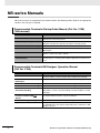
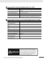
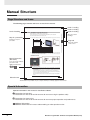
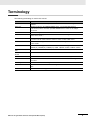


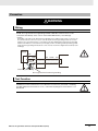


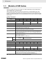
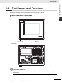
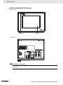

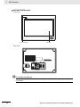
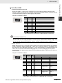
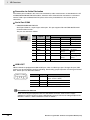
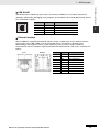
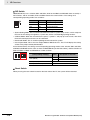

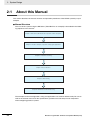
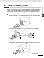
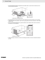
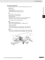
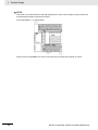
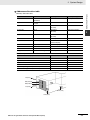

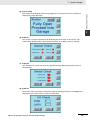


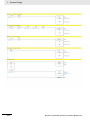
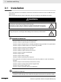

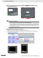
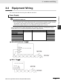

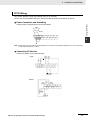
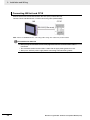


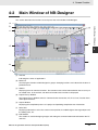

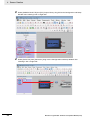

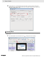

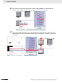
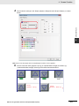

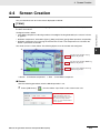
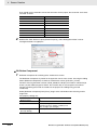
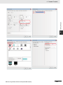

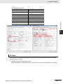
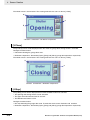


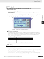

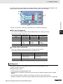
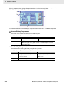

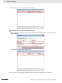
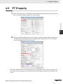
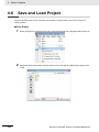


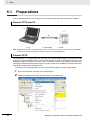
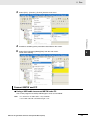
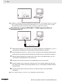

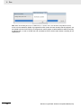

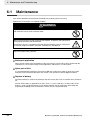

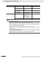
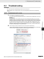


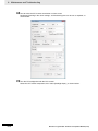
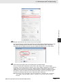
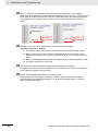
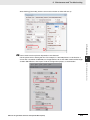
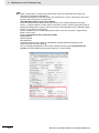
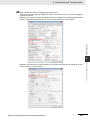

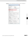

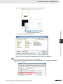

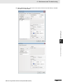
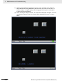


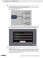
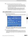


![(PDF/898Ko) [F]](http://vs1.manualzilla.com/store/data/006361117_1-d3bbb928b1dfc01d6651010e7df1a031-150x150.png)

![(PDF/1,60Mo) [F]](http://vs1.manualzilla.com/store/data/006351512_1-3bf04d39ecb748fd1eacb164958e8142-150x150.png)