1
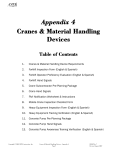
E-48
USER’S MANUAL
2
INTRODUCTION
WELCOME TO THE MONTY FAMILY
Firstly, we would like to welcome you and thank you for choosing the Monty brand
This “User’s Manual” for your new Monty electric bike contains important
information which you will need to keep your bike in good condition. It has been designed
so that you can enjoy your E-Bike safely, making the most of your time.
Please read this manual carefully before using your electric bike ( hereafter: E48),and save this manual for future reference. If you have any doubt or questions, please
contact your authorized Monty dealer. The E-48 includes a long-lasting, top-quality
engine which is not to require much maintenance from your side. Its innovative design and
safe construction is to provide you with km and km of satisfaction.
Parents or guardians should explain the contents of this manual to any minors
using the E-Bike to ensure that they have understood its contents.
The drawings and images may not correspond exactly to your model. They are
used solely to facilitate your understanding. We apologize if any part of this manual does
not correspond with the precise characteristics of your E-48.
At Monty, we always strive to improve our products, as such, we may incorporate
other new technical components to its models or change pieces without prior notice.
Always give this manual to any future bicycle owner.
The Monty family is constantly innovating to offer its clients a top-quality product
made from the best materials. Our new E-Bikes are a clear example. They provide a new
means of light and fun transport which is also ecological, silent and does not pollute. For
this reason, we want to thank you for choosing us, a decision which will benefit the
environment and all of us.
Thank you as well for dedicating a few minutes to reading this manual. We hope
that we have succeeded in making a product to you liking.
For further information about our products, visit the Monty web site: http://www.monty.es
3
ATENTION: IMPORTANT WARNING
NON-FULFILLMENT OF THE INSTRUCTIONS DETAILED IN THIS
MANUAL MAY LEAD TO MECHANICAL FAILLURES, A LOSS OF
CONTROL AND POSSIBLE FALLS, WITH SERIOUS PHYSICAL
INJURIES TO THE USER OR OTHERS, INCLUDING EVEN DEATH.
INCORRECT USAGE MAY ALSO RISK YOUR PHYSICAL INTEGRITY
AND THAT OF OTHERS.
SAFETY WARNING
DO NOT OPEN OR MANIPULATE THE BATTERY, DOING SO WILL
FORFEIT THE WARRANTY ESTABLISHED IN THIS MANUAL.
IF YOU OPEN OR MANIPULATE THE BATTERY, CHARGER OR
ELECTRICAL CIRCUIT, YOU MAY PROVOKE A SHORT-CIRCUIT AND
POSSIBLE INJURIES ( SHOCK OR BURNS ).
IT IS RECOMMENDED TO USE A HELMET WHILE RIDING.
SAFETY WARNING
DO NOT OPEN THE BATTERY NOR MANIPULITE IT, OTHERWISE, THE
WARRANTY ARE TO BE ANNULED.
MODIFYING THE TRANSMISSION, FORK OR ANY OTHER COMPONENT
IMPLIES THE E-48 NO LONGER IS TO BE CONFORMED TO THE MONTY
SPECIFICATIONS AND THEREBY ANNULS THE WARRANTY.
MANIPULATING THE ELECTRIC BIKE’S ELECTRICAL COMPONENTS WILL
ALSO FREE MONTY OF ANY POSSIBLE LIABILITY.
SHOULD YOU HAVE ANY QUESTIONS OR DOUBTS, PLEASE CONTACT
AN AUTHORIZED DEALER OR VISIT THE MONTY WEB SITE:
http://www.monty.es
CE (European Conform)
4
INDEX
SECTION
PÁG
PRESENTATION.......................................................................................................
IMPORTANT..................................................................................................
INDEX.......................................................................................................................
1. E-48 PARTS........................................................................................
2. ICONS...........................................................................
3. GENERAL NORMS....................................................................................
4. VEHICLE ASSEMBLING..............................................................................
5. USER’S GUIDE....................................................................................
5.1 How does the E-48 work ......................................................
5.2 LCD display functions............................
6. VERIFICATIONS.............................................................................................
7. ADVISES.......................................................................................................
8. SAFETY......................................................................................................
9. MECHANICS AND MAINTENANCE................................................................
9.1 Seat and Seat post............................................................................
9.1.1 Seat position adjustment ...............................
9.1.2 How to adjust the seat position.....................................
9.2 Handlebar and Stem..........................................................................
9.2.1 Conventional stem................................................................
9.2.2 Ahead stem...........................................................
9.3 Fork and Headset...........................................................................
9.4 Suspension system: Forks..................................................
9.5 Wheels........................................................................................................
9.5.1 Tyre pressure chart............................................................
9.6 Brakes.........................................................................................................
9.6.1 Rim brake system......................................
9.6.2 mechanic disc brake .................................................
9.7 Transmisión................................................................................................
9.7.1 Rear derailleur checking............................................................
9.8 Lights and Reflectors.............................................................................
10. BATTERY AND CHARGER..............................................................................
10.1 The charger............................................................................................
11. THE SYSTEM......................................................................................
12. ACCESSORIES...........................................................................................
13. TECHNICAL CHARACTERISTICS ..............................................................
14. ADJUSTMENTS CHART.......................................................................
15. MAINTENANCE CHART..................................................................................
16. SOLUTION CHART........................................................................
17. GUARANTEE...............................................................................................
18. FREQUENT QUESTIONS.............................................................................
19. ELECTRIC SCHEME...................................................................
20. SPARE PARTS......................................................................................
21. CLIENT FORM....................................................................................
22. CONTACT AND DISTRIBUTORS.................................................................
3
4
5
6
6
7
7
8
9
11
13
14
15
17
17
17
19
20
20
21
23
24
24
26
26
27
29
30
31
34
35
35
38
39
40
41
42
43
45
46
47
48
49
49
5
1. E-48 PARTS
1
2
3
4
5
6
7
8
9
10
LCD DISPLAY
SEAT
STEM
HANDLEBAR
REAR CARRIER
FRAME
SEAT POST
FRONT LIGHT
REAR LIGHT
REAR BRAKE
11
12
13
14
15
16
17
18
19
SEAT POST CLOSE
FORK
BATTERY
ENGINE
SHIFTING
CONTROLLER CAGE
PEDAL SENSORY
PEDALS
FRONT BRAKE
2. UNDERSTANDING ICONS
The following icons are used throughout this manual. They will help you to understand it
quicker and serve to point out important items.
Go to another point
Caution
Advise
Maintenance
6
3. GENERAL NORMS
•
•
•
•
Please read this manual carefully before riding the Monty E-48.
Ensure that the bike works correctly before riding.
It is recommended not to change any of the E-48’s components and not to add
any device which may interfere with them.
Safety equipment must be used.
4. VEHICLE ASSEMBLING
The vehicle assembling shall be done in a light, level and clean place with some basic
mechanic knowledge,. or to get in touch with the official distributor or with Monty in
order to solve any problem.
•
E-48 components:
o E-48 principal assembled part
o Front wheel
o Front fenders
o Pedals
o Front light
o Own manual
o Contact keys
o Charger
•
Required tools:
o Allen
o Spanner
o Screwdriver
o Nylon hammer
•
Assembling instructions
1. Take out all the components from the box and make sure to be all
of them and remove the protector cartons from the E-48.
2. Place the front wheel to the bike
3. Fit the front fenders to the wheels
4. Assemble the stem to the stem
5. Fit the pedals to the cranks
6. Verification before the first use of the E-48
See section: MECHANIM AND MAINTENANCE for a right assembling.
•
Battery Charge
1. La battery must be charged on the whole before the first riding.
See section: BATTERY AND CHARGE for a right charge.
7
5. USER’S GUIDE
DESCRIPTION
The E-48 is an electric bicycle with assisting pedal. A bicycle provided with an engine to
help you. This helping engine is part of a system formed by the rear wheel, battery,
controller and sensors, which performance is to very according to some conditions.
The E-48 is provided with a control display placed on the handlebar to regulate the
assisting help. The battery is charged by a charger connected to the electric system.
The E-48 has a great autonomy which can ride to places where a conventional bicycle
would be difficult to get along.
TYPE OF USE FOR WHICH THIS BIKE HAS BEEN DESIGNED
The Monty electric bicycles and their components are being designed as for normal
bicycle use along the standard routes in good state and in good conditions. Incorrect
usage other than the above or cross-county riding may lead to premature wear and tear,
loose joints and/ or component breakage, thereby causing possible falls and/or injuries
to the user. Ride only along the allowed routes set by the local rules.
This vehicle is not recommended to children under the age of 14 years old.
This vehicle is not recommended to people weighing more than 100 kg.
8
5.1 HOW THE E-48 WORKS
Steps to follow:
1º Connect the electric system:
Make sure the charger to be off. Turn the contact battery key to the position “(I)” (Figure
handlebar power display (Figure 2). The handlebar
1) next push the button (1)
LVD display is to light the screen and is to verify the size of the programmed wheel. In
the screen, in a circulating way, the battery charge level, distance and speed are to be
indicated. The E-48 is ready to perform.
Figure 1. (Battery key)
INFORMATION
To stop the vehicle: Turn the
battery key to counter clockwise,
pushing, at the same time, the key
towards inside to take the key out.
To start: Turn the battery key to the
clockwise
Figure 2. ( screen)
INFORMATION
The LCD display has 4 buttons to be
used as:
1- Power: To start or to stop
2- Set: selection of functions
3- Up-arrow:
To get up
selection
4- Down-arrow:
To get
selection down
the
the
Verify the programmed wheel size to correspond to the assembled one. A
wrong information can alter the speed and distance ones.
2º To initiate the riding of the vehicle
To begin is necessary to pedal forwards and the engine is to start automatically. The
engine is to go on while the pedals are turning as well. The PAR control system serves
so that the engine power were proportional depending on the power applied to the
pedals. (More power on the pedals = more power in the engine), (less power on the
pedals = less power in the engine).
9
Remind to take out the bicycle rest before getting on the E-48.
3º How to stop or decrease the speed
The assisting engine and the mechanical transmission are to be interrupted without
pedalling and the brake levers shall be clamped to stop the E-48 and the assisting
engine as well.
4º To stop the vehicle
Once the route has been finished, the electric system must be stopped. First, the
display must be off by pushing the power button
battery must be disconnected with the contact key.
. Once the screen is in White, the
The battery charge level can also be verified directly by pressing the
button placed in the superior face of the battery.
ASSISTING WAYS:
The E-48 is provided with a LCD display on the handlebar where all the information is
recorded and serves also as a control panel to select the way more required to one
necessities.
With the display on position ON, the light display can be changed directly through the
UP and DOWN arrows.
There are 6 proportional assisting levels to the pedalling and 1 manual assisting way
(auto).
The proportional assisting levels works approximately as follow:
level "1" : 35%-50%
level "2" : 50%-60%
level "3" : 60%-70%
level "4" : 70%-80%
level "5" : 75%-90%
leve "6" : 85%-100%
(Engine power ratio)
The AUTO assisting way works with the power vary manual.
See section: LCD DISPLAY FUNCTIONS
Important: The brakes, for better safety, can stop the engine working if
they are pressed
Important: Check the section: VERIFICATIONS AND SAFETY before using
the vehicle
10
5.2 LCD DISPLAY FUNCTIONS
Functions:
• Actual speed
• Total distance
• Partial distance
• Time
• Power level
• Battery level
• Assisting instructions
• Break-down
• Screen light
• Wheel size selector
Figure 3
1. The button (1)
is the one to get on or to get out
Press the button to show the km, actual speed, assisting way, battery level and
the power level on the screen.
Press the button again to get the system
off.
2. The assisting way can be varied by the arrows.
from the way
to the first proportional one , to the second, etc. and vice versa.
has three functions.
3. The button (2)
1. The display light works pushing the button while riding. The light goes off
automatically at 5 seconds. When the light icon is in position intermittent,
the light intensity can be varied by the UP and DOWN arrows in 5 levels.
2. If the button (2) is pressed two times
the icon
is let in
intermittent position and the partial distance is shown. To get the indicator
partial to Zero, press the DOWN arrow when it is shown in this indicator.
3. To select the wheel size the button
must be pressed, continuously
is let in intermittent position in the
during 10 seconds. Then, the icon
superior left side. Now, the size can be varied with the arrows. Once, it
has been selected, press again the button
to confirm.
4. The
icon means that there is something wrong in the electric system. The
intermittent code number is to inform where the problem proceeds. Remember
this number for any technical asking. Some problems can be solved by only
starting again the system or stopping and initiating the display and battery
simultaneously.
5.
11
In case to initiate again the system, wait some seconds to get it cold
Code “02” indicates that the controller has got off by a strong intensity. If this
code persists once the system has been initiated again, some part of the internal
system or the controller may have been damaged.
Code “03” Indicates that some of the three cables have not worked for nearly 2
seconds. If the problem persists once the system has been initiated , this means
some of the 3 connections are broken or loose.
Code “04” Indicates the voltage to be under of the limits .
Code “05” Indicates the problem coming from the brakes.
This state must disappear if the brake can be unblocked.
levers and the cable as well.
Check the brake
Code“06” Indicates that there is something wrong on the pedalling sensor.
Code “07” Indicates a problem in the accelerator. It can be solved by initiating
the system or the speed.
Code “09” Indicates that a protection has been activated by a strong tension (
>53.5 V). The system is to stop.
Code “08” Indicates an internal controller item has been damaged.
The LCD display shows
information
distributor
in
following areas:
Figura 4
1234567-
the
the
Engine stem
Actual speed
Battery level
The assisting way
Distance and travelling time
Light icons, break-down
Km icons and special functions
6. VERIFICATIONS
Verification before using the vehicle for the first time:
The E-48 has been verified at the factory before being delivered , however, before using
the vehicle for the first time, the following below parts should be checked:
12
• Correct position of the front and rear brakes: levers, V-brake, disc and cables.
• Correct tight of the wheels nuts.
• Correct pressure of the tires.
• Correct wheels alignment.
• Correct pedals fitting ( they shall be fitted strongly ).
• Correct tight of the quick-release clamps
The E-48 does not need any initial lubrication and it is prepared to travel the first km
without any type of maintenance. Afterwards , the standard one
The E-48 and its components must be checked before using the vehicle. Remember
that in the case that a problem is detected that you can not fix, please contact with the
authorized distributor
Make as normal the following checking before riding the E-48.
Verifications before riding the E-48:
• WHEELS
•
•
•
•
•
•
HANDLEBAR AND STEM
HEADSET AND FORK
SEAT & SEAT POST
BRAKES
TRANSMITION
BATTERY AND CHARGER
It is very important the brakes to work properly for one security and for
the others. The brakes system must be verified before any route and the
E-48 should not be used if a problem is detected.
See section:
MECHANICS AND MAINTENACE to solve the above
mentioned problems.
7. ADVISES
• Ride with care.
See section. SAFETY.
• Use the right gear
• Not to exceed of the limit weight. No passenger is allowed on the E-48.
• Plan your route according to the autonomy of the vehicle.
• A programmer by the charger plug is to help in the charger task.
• Protect the E-48 against thieves. Use a lock for more security.
• Do not get on the E-48 with the rest displayed, this item is designed only to
support the E-48 weight.
• Keep the E-48 clean for a better performance of the vehicle.
13
•
Do not watch the E-48 with any pressure water system. Avoid water entering
into the bearings.
Efficient pedalling :
Get used to the right gear:
The short gears (1,2,3) are for starting and on the slopes/ pending.
The long gears (4,5,6,7) are for a quick ride and on the even routes.
8. SAFETY
Important norms
•
•
•
•
Respect the traffic lights
Respect the traffic signs
It is recommended to use helmet for one safety
Keep on the one’s right side and pay special attention when motorized vehicles
are present.
Safety elements (Protection, visibility, circulation)
Use a bicycle homologated helmet, right clothing with reflecting parts and not too much
loose which could get hooked up to any part of the vehicle. Gloves and sport shoes
also increase comfort and safety
Local drive rules
Be aware of all the local drive bicycle rules.
Most countries have specific laws pertaining to bicycles and cycling. Contact local
cycling clubs or the relevant Department of Transportation (or equivalent) for specific
information regarding these laws. ( Check the Town House web site)
Attention while riding
One must be aware of any incident which may happen while riding such as, how avoid
the potholes, the grids of the drains or edges which could help the wheels to skid. To
avoid any obstacle, it should be in a transversal way with an angle of 90º, and if one it
is not sure , get off of the vehicle.
Riding with poor luminosity
Be prudent on riding with poor light. The E-48 is provided with a light and reflector set.
Keep them on. Use the front and rear light at any time required. It is convenient to bring
striking and reflecting clothing, specially during the night .
Take care with wet conditions
The rain reduce the visibility and the grip as well. Ride with the low gears on the turns,
on the zebra pass or sleepy areas in rain and wet conditions. Avoid riding on rainy days,
days with heavy snowfall or through flooded areas..
Take care overtaking cars
If a car comes on your way without indicating it or if someone opens the parked car door
while you are overtaking the car, a serious problem could happen. Use the bell to make
you noticed at any time required..
14
Be cautious before a long route
Remember to bring a kit for repairing a flat tyre, such as a tube, the required tools and
a pump.
It is advisable to bring a tool for everything and a first-aid kit, in case of a long route.
Use the brakes with precaution
Keep a moderate distance with the other vehicles and other objects. Calculate the brake
capacity with the distance.
To stop the vehicle grip both levers at the same time.
The excessive use of the front wheel can provoke a skid on the front wheel, even the
rear wheel may lost contact with the ground, making lost the control of the user and
consequently a fall.
Note: As with any other activity, the use of this vehicle implies certain
risks. To get the E-48, such risk must be assumed by the user. In no
case the dealer or manufacturer are to be liable.
Avoid making unsafe actions while using the E-48
Many cyclist accidents could have been avoided if the common sense had been
applied.
- The hands always on the handlebar: any small imperfection of the road can provoke a
vibration or a sudden turn on the front wheel.
- Not to ride with object hanging from the handlebar or from any part of the frame, they
could touch the spokes or provoke a sudden handlebar turn, causing the vehicle lost
control.
- Do not ride under the alcohol effects or under any medicament which can reduce the
capacity of riding. The E-48 requires a good coordination of movements and the user
shall be always with precaution of anything happening round him.
- Never carry any additional passenger. The E-48 is designed to be ridden by one sole
person. Resides, it is advisable not to increase the limit weight,.
- Never ride with earphones as they reduce the ability to hear other vehicles.
- Never hold oneself on another vehicle while riding.
Important: Get the seat springs covered in case of fitting a kid seat in the
rear.
ATENTION: As any mechanical device, the E-48 is to wear down with
different efforts. The different materials and components used may react
differently to this daily decline. If the lasting life of a given component
has been exceeded, it may suddenly break, injuring the user. The cracks,
scratches or discoloration in the areas subject to intense use indicate
that the component has exceeded its useful life and must therefore be
replaced.
Caution: In case of changing the cranks or tires, the distance between the
wheel and the toes ( feet ) on turning may be reduced, thus putting at risk
the cyclist’s safety.
15
Attention: In case of changing the cranks, pedals, tires, fork etc., the
angle inclination can be reduced, thus putting at risk the cyclist’s safety
9. MECHANICS AND MAINTENANCE
Many of the specific adjustments and general maintenance detailed in this manual can
be done with Standard tools, which one may have at home. Nevertheless, we
recommend to be carried out by a Monty official dealer who, in addition to the necessary
expertise, will also have the tools needed for each item.
9.1 SEAT AND SEAT POST
The height and position of the seat must be according to the right position of the user. A
wrong position can provoke physical problems to the user. The seat must well be fitted
to the seat post and the seat post to the frame well aligned.
9.1.1 SEAT POSITION ADJUSTMENT
•
The seat can be fitted in three parameters.
1. Seat height
2. Seat Inclination
3. Seat rear position
1. The seat’s height is the most important to be comfortable and be able to pedal
safely and efficiently. This adjustment is based on the length of the cyclists leg.
There are numerous specialized methods to choose the height depending on the length
from the groin area to the base of the foot. It is recommend a simple way as follow:
With the seat in a horizontal
position, sit on the bike, ideally, it
could be someone else holding the
bike steady or use a nearby wall for
support.
With one of your heels, press down
on either pedal, stretching the leg
as much as possible. This is the
correct height. (Figure 5)
When riding, the leg should not be
stretched out to the maximum when
the pedal is in the lowest position.
Figure 5
16
The seat adjustment is very personal See section:
. To regulate the height, the seat post release"
quick release must be open, later, the
right height must be selected and
close the quick release properly. The
seat post height must be proportional
to the rider’s height
“ How to adjust the quick
Never extend the seat post
beyond the indicated line on the
tube, as shown in point 1. See
(Figure 6).
Figura 6
2. Seat inclination. This adjustment is the most delicate and personal towards the user.
Generally, it is horizontal or with the tip slanted slightly downwards. Try different
positions until finding the most comfortable.
This adjustment is made by loosing the screw (1) (allen 6 mm) underneath the seat,
set the required inclination thigh the screw. The recommended torque value is (20-25
Newton). See (Figure 7).
3. Seat rear position: This seat adjustment implies moving the seat forwards or
backwards with respect to the seat post. Generally, the seat is centred to the stem
Placing the seat further back generally implies having to bend forward more to reach the
handlebar and excessive strain on the quadriceps muscle group.
To adjust this position, open the same bolt (1) (allen 6 mm) used to get the right
inclination (Figure7).
It is recommended to set at
the same time: The
inclination and the rear
position.
Figure
17
9.1.2 HOW TO ADJUST THE QUICK RELEASE
Quick releases clamp systems do not need tools, they are frequently used for seat
stems, axles and folding systems.
The quick releases consists of two principal parts which must be adjusted
a) The blocking lever which applies the force and.
b) The nut to adjust the lever’s strength.
For the proper and safe clamp adjustment, follow the following steps:
1. Turn the lever to the open position ( “open” is engraved on the lever ). See Figure 8
Figure 8
Figure 9
2. Choose the desired height while respecting the maximum indicated (Figure 6).
3. Turn the lever to close ( “Close is engraved on the lever”). (Figure 8)
4. If the lever is easily set to the “Close” position (less than 50 N (Newton ), this means
that it is not tight enough, in this case, open again the lever to the “OPEN” (Figure 9)
and tight the quick release again clockwise until noticing is well tight
5. Turn the lever to the “close” position. Once fastened in the right position (“Close” is
engraved on the lever) Figure 8
6. If the force required to turn the lever were excessive (more than 200 N (Newton)
repeat the previous step, turning the bold counter-clockwise. Do this as many times as
necessary until safe
The quick release must be positioned in a way that it does not interfere
with other components and easy to be handled
In case of doubts or if you can not set the adjustment, take E-48 to an authorized dealer or
contact us
9.2 HANDLEBAR AND STEM
The handlebar and stem must be fitted correctly at the suitable position of the user and
well tightened. .
18
Check once a month to ensure that the stem is aligned with the front wheel. Also check
the joint between the stem and handlebar, trying to move the latter with respect to the
front wheel. Check as well no cables to be stretched or pinched when moving the
handlebar. Verify all the screws and bolts to be tight.
There are two kinds of stems
• CONVENTIONAL STEM is the one to be inserted into the fork tube and the height
can be regulated. The headset is provided with threads.
• A-HEAD stem is the one to be fitted, externally, to the fork tube and not possibility
to regulate the height. The headset is provided without threads
9.2.1 CONVENTIONAL STEM
Adjustment of the handlebar height:
A. Remove the rubber cap and loose the screw. Figure 1 in (Figure 10) counterclockwise (Allen 6mm).
B. Move the handlebar sideways to unblock it and adjust to the designed height
Caution: Never raise the stem above the line on the stem as indicated in
point (1). See (Figure 11).
Figure 10
Figure 11
C. Tighten the screw (1) clockwise until completely set. The recommended torque
value for the stem: 20-30Nm. ( Newton )
Adjustment of the alignment:
A. To set the handlebar perpendicular to the front wheel, use the same system like
the height adjustment one.
Move the handlebar sideways to unblock the handlebar and fit it to the required
height
Adjustment of the handlebar inclination:
A. Loosen the screws (3) counter-clockwise as seen in (Figure 12). (Allen 6 mm.)
19
B. Chose the required inclination suitable to ones necessities. And verify the
handlebar to be centred to the stem.
C. Tighten the screws (3) clockwise . The recommended torque value is: 15Nm. (
Newton )
Figure 12
Adjustment of the stem inclination:
A. Loosen the stem screw (2) counter-clockwise, indicated in the (Figure 12).
(allen 6 mm.)
B. Chose the inclination required. Take note of the indicated position since the
handlebar inclination can be effected.
C. Tighten the screw (2) clockwise. It is recommended torque value :17-20Nm. (
Newton )
Check the handlebar and stem for wear or stress signs. If you find any scratches, dents,
warping, discoloration or cracks, remove the affected piece immediately.
If you doubt whether or not the handlebar is safe to use, do not use the E-48. Take it to an
authorized dealer
9.2.2
A-HEAD STEM
Adjustment of the handlebar height:
This kind of stem can not be regulated.
Adjustment of the handlebar inclination:
A.
B.
C.
Loose the screws alternately counter clockwise (A) the ones which fix the
handlebar to the stem (Figure 13). (Allen 6 mm.)
Choose the required inclination suitable to ones necessities. Verify the
handlebar to be centred to the stem.
Tight the screws (A) clockwise. The recommended torque value of the
handlebar : 15Nm.
20
Figure 13
Figure 14
Adjustment of the headset alignment:
A. To place the handlebar perpendicular to the front wheel. Loose lightly the screw
(B) and the screws (C) alternately.
B. Move the handlebar sideway to unblock it and place it properly.
C. First tighten the screw (B) to compress the headset forwards and backwards
with the front brake, tighten the screw again (B) next tighten the screws (C)
alternately to get a solid junction. Verify the headset adjustment.
Adjustment of the stem inclination:
A. Lose the screw counter clockwise (E) the ones to fix the stem, indicated in the
(Figure 14). (allen 5 mm.)
B. choose the required inclination most suitable to one’s necessity. Take note of the
marked graduation (D). The handlebar inclination can be effected as well.
C. Tighten the screw clockwise (E). The recommended value torque is:17-20 Nm. (
Newton )
See section: "FORK AND HEADSET" to get a headset and stem
adjustment properly.
9.3 FORK AND HEADSET
The headset includes all the bearings which allows the fork, stem and handlebar to turn.
This section describes how to inspect, lubricate and adjust the fork and headset..
If the Bike is provided with a suspension fork, please see section referent to suspension
forks.
Inspection
Inspect the headset and check to make sure that it is neither too tight nor loose. If either
of these , in this situation do not use the E-48 and take it to the authorized dealer.
21
How to check the plays of the Headset
Place oneself over the horizontal tube with both feet on the ground. Squeeze only the front
brake while moving the vehicle forwards and backwards. Check if the headset is loose.
The fork and stem can have a small play
How to check the adjustment of the headset
Place oneself over the horizontal tube with both feet on the ground. With the front wheel
resting on the ground, turn the fork and stem to the left and to the right and vice versa.
Feel if the headset is excessive tighten, in a way that it gets broken in some points by
turning it
Adjustment (only A-Head)
If the Headset has a play or the fitting is not set properly, it must be tighten in the same
way indicated. 9.2.2 A-HEAD STEM/ Adjustment of alignment.
Caution: Adjusting the Headset requires special tools and expertise. It is
recommended to check it with an authorized dealer.
Attention: An incorrect headset adjusting may cause one to lose control of
the bike and fall down. Ensure that the headset and stem to be correctly
fitted before each use.
LUBRICATION
The Headset should be lubricated once a year. This requires specific know-how, expertise
and special tools, for this reason only an authorized dealer should do it.
1
9.4 SUSPENSION SYSTEMS: FORKS
The suspension forks allows the front wheel move , absorbing road irregularities and
lessening the vibrations which the rider actually feels. The suspension forks need to be
lubricated on a regular basis so that they work smoothly and their useful life be extended.
This manual is a supplement to the maker fork information, If you have not received this
information, one can unload it from the maker’s web site or get in touch with Monty
INSPECTION
Before riding the E-48, make sure that the suspension is working correctly. Do not use the
bike if there is not enough distance between the fork and the Wheel.
LUBRICATION
Follow the instructions regarding lubrication and maintenance in the suspension manual.
9.5 WHEELS (mounting, rims, tires and tubes)
22
The wheels ( rims and tires ) are an extremely important part of the E-48. Check the right
pressure of the tires and their condition and the rim as well. This is to depend on riding
conditions, ground contact, the braking system and safety in general.
One should periodically check to make sure that the wheels are securely held, that they
are centred and do not buckle when moving. One should also ensure that the tires are
properly inflated and that the thread is neither cracked nor worn down. The rim surface
where the brakes make contact should be free of grease. Check the spokes not ot be
broken or lose. The hubs should turn gently without moving side to side. Check it by
moving the wheel sideways.
Caution: A wheel in poor conditions may cause the user to lost control
and a possible fall. Check the wheels each time before riding and do not
use the bicycle until any possible problem had not been solved.
Wheel mounting
To mount the wheels, follow the following steps:
1. Mount the wheel to the fork ( front wheel and rear wheel ), ensuring that the axle
is well placed in the fork groove.
2. Place the fixing nut
3. Tighten both nuts on either side of the axle by alternating and progressively
tightening both in turns.
4. See the section: Torque value chart, for a right tight
Check to ensure that the axles nuts are correctly placed as specified above. If they are
not, readjust following the same steps or take the E-48 to an authorized dealer.
Rear wheel
The rear wheel holds the E-48 engine, and the engine cable comes out from one side of
the axle, in case of a flat tyre or to change the tyre, the wheel can be moved partially and
work on the contrary side of the axle.
If you need to remove the Wheel completely, one must follow the cable to find out the
connector. Normally the connector is found in the exterior side. Depending to some
versions, the side cover underneath the battery to disconnect the engine cable.
VERY IMPORTANT: Take note of the connections before disconnecting in order to
connect them correctly later on. An incorrect connection may cause a severe problem. We
recommend an authorized dealer to carry this work.
Lubrication: The hubs must be lubricated on time per year. This operation requires
some knowledge and special tools. We recommend an authorized dealer to do it.
Caution: The rear Wheel has to be carefully mounted, ensuring that the
motor cable comes out of the axle is not pinched or bent. The axle is
provided of special washers to avoid the axle turning. Place them
properly
To remove wheels with a V-Brake system, the brake bridge has to be
open first. Another option is to get the tyre flat.
23
Rims
Information of the rim wear and associated risks.
As the rim surface is part of the braking system, it is to be wear down. Using a bicycle with
worn rims implies a serious risk for the user. For this reason, please pay special attention
to this component.
Some rims are engraved with a line to indicate the wear level of the rim. In this case, the
user must ensure that the surface does not reach such a level, if it does, the rim must be
changed. If you have any questions or doubts about the rims, contact n authorized dealer.
The rims are provided with a warning icon such as that in figure 10.11
CAUTION: Excessive wear of the braking
surface may cause a failure in the holding system
and lead to injuries. Inspect the brake surface area for
wear. Do not use rims that are severely worn.
Figure 15
Tires
The tires thread has to be in good condition and not to be worn, cracked or scratched. The
thread pattern must be in good shape for a right traction.
The tire’s measurements are printed on the lateral sides. Make sure when changing the
t1yre to be compatible with the rim and bicycle.
Caution: When replacing the tyre. Make sure that it is compatible with the
rim and tyre of bicycle. E-bike tires have unique characteristics compared
to standard tires.
Tyre pressure
Tires must be inflated to the right pressure to ensure the bike works properly. that is to
say:
- With a 4 kg (high ) tyre pressure, it is to achieve a greater speed though the riding is to
be less comfortable and more nervous, with the added risk of falling on curves or slippery
surfaces.
- With a 2.5 kg. ( normal riding ) tyre pressure, greater comfort is achieved.
You can adjust the tire pressure between 2.5 and 4 or even 4.5 kg to adapt to any
requirement.
The valve is like the “American” type as the ones used by the cars. However, it should be
avoided filling the tires in the petrol stations, etc.. Use a pump with a suitable nozzle to the
valve. To inflate the tyre, remove the valve cap and place the nozzle on the valve,
ensuring that no air escapes. Check the pressure and place the cap back on the valve,
ensuring air not to escape, verify the pressure and place the cap back on the valve to
keep it from getting dirty.
If the inner tube is flat, it is recommended to change it and not to fix it.
Before riding your bike, check the tire pressure ( inflate the tires without exceeding the
limit printed on the lateral sides of the tires ), the tires wear, the fitting and the alignment of
the rims.
24
9.5.1 PRESSURE TABLE
Wheel
Front
Rear
Mínimum pressure
Bar
Kpa
PSI
2,8
280
40
2,8
280
40
Maximum pressure
Bar
Kpa
PSI
4,6
460
65
4,6
460
65
Recommended
Bar
Kpa
PSI
3,0
300
42
3,5
350
50
9.6 BRAKES
Ensure the brakes to work properly. They must perform and stop the bicycle within a safe
distance. The engine should stop by squeezing either brake lever brake. Ensure the
brake shoes / pads not to be excessively worn down.
00.
It is extremely important the brakes to work correctly for one safety and for
the others as well. Etc.. As any braking system, an incorrect adjustment,
poor maintenance or a bad use of the brakes may cause to lose the control
of the E-48 with all the consequences that this might imply.
Never use the bike if the braking system is not working correctly or if you
suspect any type of problem either with the brakes or their cables. If the
E48 does not work properly, fix it or take it to an authorized dealer.
Verify the brake system before using the E-48 and not use it if you detect
any problem.
Brake adjustment and working
To brake or stop the E-48, the two brake levers must used properly, according to the
circumstances and the engine is to stop automatically. The brake system is: Left lever to
brake the front wheel and the right lever to brake the rear wheel.
Brake system
In the electric bicycles, the action of the brake levers no only act on the rims or disc, but
on the engine as well, being disconnected at any time the brake lever is used. The E-48
models are provided with a rim and mechanical disc brake.
The brake system allows one to slow down, being a critical function on the bike. This
section describes how to inspect, adjust and lubricate the brakes of the E-48. Read the
specific information about the exact type of the brake to assemble.
Adjusting the braking system is difficult if one does not have the
necessary know-how, experience and material. It is strongly
recommended to make the brake adjustments by an authorized dealer.
9.6.1 RIM BRAKE SYSTEM
In these types of brakes, the levers are connected by means of cables. By squeezing the
brake lever, the shoes squeeze the rim, thereby slowing down the Wheel and the bicycle
cables.
25
These systems consist of the following components:
- Rim
- Brake lever
- Cables and casings
- Brakes shoes/pads
Never use this type of brake on the wheels designed for disc brakes. The rims require a
flat surface for the brake shoes to work properly.
Verification
Before using the bicycle, squeeze the brake levers hard. The lever should never touch
the handlebar. If it does so, the cable length will have to be adjusted as it described
forwards.
When the brakes are not being pressed ,the brake shoes should be at 1-2mm from the
rim. The brake shoes must be aligned with the rim surface. If the brakes are to loose, tight
or unaligned, adjust them before using the E-48.
One should bear in mind the brake shoes ’angular alignment with respect to the rims to
keep the brakes from grating. Used shoes and some new, V-type brakes may not require
this alignment.
Check the brake shoes , at least, once a month. They have small groves on their surface.
If any of these are less than 1mm deep, they will have to be changed. If the original brake
shoes do not have any grooves, they will have to be replaced when there were only 3 mm
left of the rubber block with respect to the metal support.
Setting the brake shoes vertically should be such that the rim’s edge were 1mm above the
brake shoes edge. The brake shoes have to make contact with the rim perpendicularly to
the brake surface as shown in . (Figure 16)
The brake shoes must also be slightly tilted to the direction in which the wheel turns.
Otherwise, the braking will be less effective and the braking is to make a lot of noise..
(Figure 17)
Check the brake cables once a month to ensure that they are not bent or rusted and that
there are no broken threads. Also check the coating to detect ant loose cables, bent ends,
cuts and wear. Remove any defective cable or coating .
The lever and brake shoes bolts should be tightened every three months. The V-brake
type bolts must also be tightened every three months.
Figure 16
Figure 17
AJUSTMENT
How to adjust the distance between the brakes shoes and the rim
To increase the distance between the brake shoes and the rim, turn the screw (Figure 18)
clockwise and to reduce the distance, turn it counter-clockwise. If it is not possible to
adjust the brake shoes as it is indicated above, loosen the cable bolt clamp and reattach
the cable.
26
Figure 18
How to adjust the brake shoes alignment
Loosen the brake shoes bolt.
Follow the instructions above detailing how to inspect for the brake shoes alignment.
Afterwards, squeeze the brake lever as hard as possible approximately 10 times. Ensure
that the cable have not come loose, that the brake shoes are correctly aligned with
respect to the rim and that the pads do not touch the tires.
How to adjust the brake shoes alignment
V-brakes type: Disconnect the joint tube and with a hand, squeeze firmly the brake shoes
against the rim and from the other hand, pull the tub backwards from the joint and raise it
up. Once disconnected, the tube is to come free. To closet he brakes, follow these same
instructions in reverse order.
Lubrication
The brake lever pivots should be lubricated every 3 months with a synthetic lubricant, the
same as it is used for the chains.
When installing a new brake cable, it should be lubricated with a thin coat of synthetic
lubricant.
9.6.2 MECHANICAL DISC BRAKES
Instead of using a brake shoes to press on the wheel rim, a pad squeezes in a disc placed
on the front wheel or rear wheel hub. The disc is fitted to the axle by means of bolts on the
left side. The brake is activated by means of a cable connected to the brake lever.
The braking system consist of the following:
- Brake lever
- Brake cable & casing
- Brake disc pads
CAUTION. The disc brakes may be very hot after using them. Be careful
when inspecting them. As with other bicycle parts, avoid placing fingers
inside the disc.
Squeeze the brake levers 10 times before riding. The levers should not touch the
handlebar.
Ensure that there is no oil, grease or any other matter on the disc. The disc is part pf the
braking system and should always be kept clean. Remove the pads from their supports for
a deep cleaning. Do not use any cleaning products, degreasing liquids or solvents to clean
the disc. Only use isopropyl alcohol.
Ensure, once a month, the disc brakes not to be worn out. If the brake pads are less than
1 mm thick, they will have to be changed. Also, check the pads to be correctly positioned:
A distance between 0.25 and 0.75 from the disc when not using the brakes. Turn the
27
wheel while not pressing the brake lever. The pads should touch the discs as little as
possible.
The brake cables should be checked once per month to ensure that they are not twisted
or rusted, no broken threads or ends, and check their casing for cuts or wear. Change any
defective piece.
AJUSTMENT
• How to adjust the separation between the pads and disc:
Turn the pad’s adjustment screw. To increase the separation, turn it counter-clockwise
and to reduce the distance, turn it clockwise.
• How to align the brake to the disc:
Loosen the brake mount bolts. Squeeze the lever completely and gradually tighten the
bolts as it is indicated in the inspection section above.
• How to remove the brake pads
Remove the Wheel. With the fingers or a thin-nosed pliers, grab hold of the brake pad tab
and pull..
• How to remove the wheel:
With disc brakes, the braking system shall not to be removed. Carefully slide out the disc
from the brake. When the wheel is to be fitted, carefully the disc must be guided between
the pads. If the disc is pushed to the edge hard against the pads, they could be fractured
or damaged . as a result they would have to be replaced.
Important: The left brake lever corresponds to the front wheel and the
right brake lever to the rear wheel.
9.7 TRANSMISSION
The transmission must work properly. It has to be clean and lubricated, not to make noise
and the gear mechanism must work smooth and exact.. All the links of the chain must
pivot well and without noise. So, any link of the chain can be deformed.
A correct transmission is crucial for a right working.
Transmission set and adjustment.
The E-Bike 48 transmission set carries power from the rear wheel by means of: Pedals,
chain ring & cranks, chain and freewheel
This section explains how to inspect, adjust and lubricate the transmission set.
Pedals
Inspect the pedals every three months. Check to make sure the pedal reflectors to be
clean and correctly positioned. Make sure the pedals to be well fixed to the cranks.
To check the pedals to work correctly, move the pedals up and down and left to right. If
they are either too soft or rigid, take the E-48 to an authorized dealer to have them
adjusted, lubricated or replaced.
Cranks set and chain
Inspect the crack set every three months, check to ensure the bolts joining them to be
tight.
Check the chain every three months for wear. Each complete link of the chain measures
25.4 mm. If twelve links in the chain measure more than 30.8cm, the chain should be
28
replaced or it is recommended to change it at the 1.500 km. Special tools and expertise
are required to change the chain. Please take the E-48 to an authorized dealer.
Adjustment
The adjustment of the transmission set composed of freewheels, chain, chain wheel and
pedals must be made by an authorized dealer since it is required specific tools and
expertise.
Lubrication and cleaning
Clean and lubricate the chain and sprockets once a month. Avoid excess grease falling on
the rest of the bike by placing a rag behind the chain. Once the chain has been lubricated,
wipe off any excess grease with a rag.
Do not use gasoline to clean the sprockets as it is highly inflammable and leaves a thin
film of grease when it evaporates. Use a degreasing liquid and brush the sprockets to be
clean.
Caution: The left and right pedals are stamped to indicate what side they
correspond to: “R” = right and “L” = left.
Figure 19
Figure 20
9.7.1 Setting the rear derailleur
The speed system changes the freewheel derailing the chain and moving it from one
sprocket onto another..
Inspection
The derailleur gear system is considered to be correct if its silent. If after every change a
small temporary sound is heard, it may need to be adjusted. If it can not be adjusted and
the sound increases, take the E-48 to the an authorized dealer.
Check once a month the cables are not to be bent or rusted and check the cable not to
have broken threads or deteriorated ends. The casings shall be verified as well to detect
any lose cable, bent ends, cuts and wear. If there is a problem detected, no use the E.48,
change the cable or take the E-48 to an authorized dealer.
29
Once a month check the shift lever to work properly. Every time a gear is changed, the
sprocket should be moved in such a way that the chain is being moved smoothly and
without jumps. The chain should never fall off of the internal or external sprocket.
Adjustment
The adjusting of the derailleur must be done with the bike firmly held on the work bench or
with someone holding the rear wheel up in the air so that the transmission and the
derailleur can work on a relaxed position.
17
How to adjust the derailleur
The rear derailleur has two screws to regulate the limits, inner and outer, of the travelling
which can be set in two different places , depending on the derailleur model.
- Set the outer roller in line with the smallest sprocket, using the regulating outer screw
(H).
- Set the outer roller in line with the largest sprocket, using the regulating inner screw (L).
To check it, try to pedal with all the possible freewheel options:
- If, when in the intermediate positions, a noise is heard when changing the gears or the
chain does not move to another sprocket smoothly, examine the cable tension ( set on
the shift lever or in the same change ) to adjust it properly.
- if the chain falls from the small sprocket, tighten the outer limit screw (H), a quarter turn.
- if the chain does not fall from the small sprocket, loosen the outer limit screw (H), a
quarter turn.
- If the chain falls from the large sprocket towards the spokes, tighten the inner limit screw
(L), a quarter turn. If the chain does not move up to the big sprocket, loosen the inner limit
screw ( L), a quarter turn.
If the sprocket system can not be lined up as it is explained above, take the E-48 to an
authorized dealer.
Figure 21
Figure 22
30
Figure 23
Figure 24
How to set the gear mechanism system
To avoid any mechanical problem ( chain falling off, noise when pedalling, etc.) the below
recommendations should be followed::
- Set the right speed changing just before the beginning of the climbing or to avoid any
obstacle.
- when one is going to change the gears, keep pedalling but without pushing the pedals
excessively, using the shift lever till the chain is placed on the required sprocket
- Avoid changing the gears while struggling to move uphill, for example, even if the
synchronized systems allows to do so.
In the E-48, the shift gear is necessary in order to get the maximum performance of the E48. This model is provided with a Shimano derailleur of 6 or 7 speed, to help the
interaction between the rider and the vehicle.
Las E-Bikes use a chain-based derailleur system. Changing the gears is done by using
the right-hand shift lever or the left one depending on the model..
Chose the gear which offers the most comfort while riding. It is possible to change the
gear while chain is moving forward. Never change the gear while the chain is still or
moving backwards.
Use the appropriate speeds before any change in the terrain.
Continue pedalling gently while sifting the gears.
1 and 2 speeds for the starting and strong u-hill.
3 and 4 speeds for even surfaces or light up-hills.
5 and 6 for the descending and high speed.
To change the gears, smooth the pedalling while you are using the shift lever, and without
letting pedalling, change the gears one by one. Before stopping, change to the speed 1 or
2 2.
Lubrication
31
The pivot points and the pulleys should be lubricated each month. Any cable which has
been replaced should be greased in those areas where they are covered or where they
are rubbed against another component.
Chain tension
The E-48 model is provided with a rear derailleur with a chain tensor. If the chain has the
right length and the derailleur works correctly, the right chain tension should be
maintained automatically.
Lubrication
It is very important to lubricate the vehicle components which do not generally require any
maintenance, at least once a year, such as the hubs, gears, pedals and chain and as any
new cable which may have been changed. Special oils should be used. Look for them in a
specialized shop. See the maintenance chart.
9.8 LIGHTS AND REFLECTORS
The reflectors reflex the light received from outside. While riding in the night or in
conditions with poor visibility, or in the case that your vehicle is illuminated by another car,
the reflector are to help to be seen. They are part important from the safety system and
they should never be removed.
Check the lights pointing in the right direction (perpendicular to the ground) and avoid any
front and rear lights clean to work properly. Verify, every two months, the washers and
item to cover them.
It is important to keep the fix system to be well fastened.
Check the local rules for the correct light system to be used on the public means. Verify
the cables to be connected to the light device, the bulbs and all the system to work
properly. If a problem is being detected get in touch an authorized dealer..
32
10. LA BATTERY AND CHARGE
The battery is the most important item of the E-48. A correct charge of the battery is
extremely important to determine the battery’s life. The battery must be charged on the
whole before using the vehicle. The battery is provided with a indicator to show when the
battery is full charged. Make sure the ignition key to be blocked to avoid the vehicle move.
The E-48 is equipped with a Lithium battery (LI) de 36 V 9 Ah. it consist of cells grouped
together in series with an electronic control charge. It does not require any maintenance
like the Lead-Acide ones(LA). It can be recharged at any time, thought, it is
recommended not to get the battery discharged completely.
Good use of the battery
The first charge of the battery is very important to determinate the battery’s life. It must be
complete (4/6 hours approx.) till the indicator shows to be full up.
The lithium batteries are very sensitive while being charged. An inadequate power supply
may damage the battery.
In general, the batteries are also sensitive to extreme temperatures.
Any manipulation of the battery by the user is to invalidate the warranty and free the
manufacturer of any possible liability.
The battery charge must be made in a dry and well-ventilated area.
The batteries may discharge itself. It is normal to decrease the charge when the vehicle
has not been used for a long time.
It is recommended to make a complete discharge every three months, later,
follow with a compete charge.
10.1 Charge
The E-48 is provided with a charger of high power. Please follow the following steps:
•
•
•
•
•
The charges must be on position: ”off(O)”, stop (F) in (Figure 26)
Connect the charger to the battery (B) in (Figure 25)
Connect the charger to the electric system
Set the charger switch to the position ,“on(I)”, start.
Once the charge is finished, set the charger in position “(O)” and disconnect from the
electric system.
Figure 25
The battery can be charged on the vehicle while is still or be removed. If the battery is
being removed, it must be handled with care. A supplied key is provided to unlock the
battery’s safety latch. (A) in (Figure 25).
33
If the battery must be removed to be charged. Unlock the battery with the key and lift it up
enough to take it out from the setting. When the charge is finished, place it again, making
sure to be well placed by sliding the battery downwards and close the safety latch.
Figure 26
Figure 27
Battery charge indicators
Red light: the charger is connected to the electric system
Yellow light: the battery is being charged
Green light. The battery is charged or disconnected
Battery fuse
The battery is provided with a safety fuse of 10 A, in case that the charged dis not work,
verify the fuse. (H) in (Figure 27), and change it, in case of being fused
Indicators of the charge level
The E-48 includes a battery charge indicator on the handlebar., (I) in (Figure 28). If the
indicator light showed a line, while using the E-48, this would mean that the battery
capacity is run out, in this case it should be charged at once. The battery includes an
indicator which can be activated by a button. “lined” (B) in (Figure 29).
Figure 28
Figure 29
34
Very important: Do not allow children to charge the battery. The electric
charge (220 v), can cause serious personal injuries or even death. Do not
charge the battery barefoot, on a damp or wet floor or in conditions which
might threaten the one personal safety. The plug of the electric system
must meet the pertinent safety conditions.
Use the charger corresponding to E-48 model. Make the charging work in
a well-ventilated area
The manipulation of the battery by the user is to invalidate the warranty
and free the manufacturer of any possible liability.
The temperature may effect the battery to work properly. In general, the battery is to work
well in high temperatures. When the temperature drops below 0 Cº, its performance can
be reduced by a third of its power. For this reason, it is probable that the charge can last
less time in winter. At 20 C, the battery shall work normally.
When the temperature exceeds 35º-40º ( or if the battery has been exposed to the sun for
a long time ) , the electric components may not work normally.
Actions which may effect or reduce the battery performance.
•
•
•
•
Constantly starting and stopping the E-48 as it can be in the cities
Constantly braking and turning the bike on and off.
Ride upwind or uphill and carrying extra weigh
Low pressure tire and braked wheels.
The above actions can influence the battery’s performance, reducing its life and the
distance to be travelled being shorter. It is recommended to take well note of them to
extend as much possible the distance which the E-48 can travel.
CHARACTERISTICS
Model
Type
Voltage
Capacity
Lifetime ( years )
Number of the chargers
Charge time
weigh
E-48
Lithium (Li-ion)
36 V.
9 Ah.
2–4
600 Approx.
4-6 hours
2,3 Kg
35
11. PEDAL ASSIST SYSTEM
Pedal assisted system (PAS)
The pedal assists to a sensor which detects the move and power of the pedals when they
are activated by the user. This system is set in the BB, transmitting the required
information to the controller for its working.
Controller
The E-48 controller is the nerve centre of the system. It consists of a small box fitted under
the battery compartment and where all the components are connected.
The controller receives all the necessary information from the brakes, pedalling sensors
(turns and pedalling force) , engine. battery, etc.., then it process to operate the E-48.
The controller is responsible of the engine to work properly and the E-48 to be safe.
Checking and handling the battery requires specific tools and know-how. Only an
authorized dealer or the Monty plant should manipulate it.
Engine
The E-48 is provided with a top-quality and resistant engine. The engine is part of the rear
wheel, designed to provide maximum service with barely any required maintenance. It can
be either a brush or brushless type, depending on the its version. The engine, as part of
the rear wheel must be well fixed as it is explained in the section: Wheels. Otherwise,
there is a risk of a serious problem. Be specially careful with the cable coming from the
axle.
Have special attention with the engine cable not to bend or damage it in any way.
Important: Avoid heavy hits to the wheel or damage the rim as the engine
could be damaged as well.
It is recommended to check it , once per year, to ensure to work correctly.
36
12. ACCESSORIES
To improve the E-bike components, many of them are provided with different types of
accessories. Such as lights to improve the visibility of the user, racks or bells. All the
accessories must be in good conditions to ensure their optimal performance.
REVISION
The screws and bolts should be inspected once a month. The right torque value for the
fender bolts is. 3.5-4.5Nm ( Newton ) and the bolts from the junction between the fenders
and the frame is 6-7Nm. ( Newton )
LIGHT SET
The light set has been designed to increase the safety of the user in conditions with a poor
visibility as it can be while riding at night or in the fog. The lights are being powered by the
E-48 battery’s. Once connected , ensure that they light up and point in the right direction
to obtain the optimal combination of shine and brightness suited to one’s requirement.
The light set must be always kept clean.
Remember that the vision can be reduced at night, therefore, it is recommended to show
down and adapt the riding to the required situation. At night, even the lights are on, the
visibility is less than during the day.
In addition, it is recommend to change the bulb set every six months because there is not
any warning system to detect it if they are broken and one may run the risk of not having
any light when you need the most
Avoid overstretching or cutting the cables. If this happens, the lights are to get off.
If the battery is discharged on the whole, the light system will let to function so , be sure
the battery to be well charged and bring a fuse as spare parts.
Peligro
INSTALLATION
In case that the vehicle is not provided with a light set, it is recommended to visit an
authorized dealer.
To change the bulbs, make sure of the original bulb’s voltage and power. In case of any
doubt, contact and authorized dealer.
HOW TO INSTALL A BULB
Locate and unscrew the bolt or the system to move the covering of the front and rear light
.Remove the bulb set in a way that the bulb can be taken out.
Take care of not breaking the bulb while taking it out.
Place the new bulb and follow the same instructions in reverse order to finish it.
LEDS
The leds have less consumption and last more time than the standard ones, however, the
change is not so easy as the bulbs.
When a leds light is disconnected, take in mind that the polarity can not be
changed . It is necessary to respect the same polarity.
Importance of the use of original parts
37
It is extremely important to use always original parts when replacing E-48 components.
Not doing so, it may invalidate the manufacture’s warranty.
Current Law
According to the following regulations:
•
•
•
•
•
EN 14764
ISO 5775-1 y ISO 5775-2
PREN 14872
ISO 9633
ISO 7636
13. TEHCNICAL CHARACTERISTICS
Note: The following characteristics may be subject to change without any prior notice. The
E-48 is not recommended for those weighing more than 100 kg
E-BIKE
Engine
Battery
Voltage
Max. speed
Autonomy
Charge time
Frame time
Fork
Stem
Gears
Brakes
Wheels
Pedals
Weight
User max. weight
Luggage max. weight
Max.load
Equipment
E-48
250 W Brushless in the rear wheel
Lithium 36 V-9 Ah
36 V
25 Km/h
35-40 Max.
4-6 h
Aluminium
Suspension 1 1/8
Adjustable
7 speeds
Disc / V-Brake
26” Aluminium
Aluminium
27,4 kgs
100 kg.
15 kg
User+ luggage ( 115 kg)
Display LCD, Lights, Carrier, Resting, stem
selector and bell.
38
14. TORQUE VALUE CHART
Component
wheels
Cranks
Brake shoes
item
Quick releases
Front nut
Rear nut
Fixing bolt
Quick release
Bolt
Hight bolt
Inclination bolt
Handlebar bolt
Fixing bolt
Adjusting bolt
Handlebar bolt
Cranck nut
Alignment
20-25 Nm
20-30 Nm
17-20 Nm
15 Nm
12-15 Nm
10-14 Nm
12-15 Nm
15-20 Nm
8-10Nm
Brake
Brake bolt
8-10Nm
Brake lever clamp
Brake shoes mount
bolts
Adapter mount
bolts:
Fixing screw
6-8Nm
11.5-12.5Nm
Seat
Seat post
Standard stem
Ahead stem
Torque value
Force
100 N*
20-25 Nm
30-35 Nm
20-25 Nm
100 N*
11.5-12.5Nm
Disc mount bolts
5-6Nm
Cable clamp bolts
Fenders
6-8Nm
3.5-4.5Nm
Support bolts
Junction bolts
between the
alignment bolts and
the frame
6-7Nm.
*Force: 9,8N = 1kgf
(1) Tight value: A par corresponds to the force applied with a lever arm. Its unity is Nm
(Newton per meter). 10 N corresponds to the force which makes 1 kg with the gravity.
39
15. MAINTENANCE CHART
This chart reflects maximum values and can vary depending on the use given to the bike
and the wear resulting from the different riding of the users. It can also vary depending on
the terrain, weather and riding stile, etc.
Component
Seat post
Handlebar/
Wheel
alignment
Hubs
Lights / reflectors
Fork / Headset
Pedals
Chain wheel
Chain
Cables
Gears
Brake shoes
Brake lever screws
Brake V-brake pívot
bolts
Brake levers
Disc brakes
Bulbs
Inspection
1 month
1 month
Lubrication
1 year
2 months
1 month
3 months
3 months
3 months
1 month
1 month
1 month
1 month
1 month
1 year
1 month
1 month
1 month
replacement
1 year
1 year
1500 Km
6 months
1 year
No partten shown
3 months
3 months
3 months
6 months
40
16.SOLUTIONS CHART
INCIDENCE
1º
2º
3º
Alter setting the battery
to charge, it seems not
to charge
When turning the battery
key, the charge indicator
does not light up
The engine does not
start when pedalling
POSSIBLE CAUSE
1.
The charger is not
connected properly
1.
Adjust the connections to ensure
good connection
2.
The battery is not in the
charge position
2.
3.
The charger does not
work properly
3.
Check the batter position to be
right ( ON/OFF) according to the
model
Check the charger light to be on
without being interrupted. Contact
to the technical service in case it
did not blink
4.
the charger fuse is fused
4.
The fuse must be changed
1.
Check the battery indicator and
recharge if it were necessary
2.
verify the fuse and replace it ( See
the technical service section )
3.
verify the connections and contact
a technical service if it were
necessary
1.
The battery is discharged
on the whole
2.
The fuse is out or it is
not well connected
3.
the key switch does not
work
1.
the battery has not been
connected
1.
make sure the battery to be on
position ON
2.
The brakes are in
function
2.
3.
The Pedal assisting is
not connected.
3.
4.
The pedal assisting does
not receive any sign
from the pedal
The engine is stopped by using the
brake lever, make sure not to press
the brake lever on starting the
vehicle..
Some models have the possibility
to disconnect the Assisting
pedalling by and a Red switch set
just under the battery. Make sure
not to be connected.
5.
4º
The engine is stopped
alter having moved just
a few meters or when
climbing a not very
steep hill
SOLUTION
In models with a sensor (magnetic)
transmission, ensure that it is
correctly positioned, just at few
millimeter separating it from the
magnetic support found at the
same height as the left connecting
rod.
5.
check the fuse and the electric
connections. See the relevant
section.
1.
Ensure the pedalling to be
properly. The engine is to be
activated on receiving the pedal
working. If the pedalling goes
slowly or interrupted by the brakes
, the engine is to stopped
Make sure the battery to be
connected correctly
it must be a faulty
electric item
1.
The engine has not
received the pedalling
force
2.
The cable has been
detached from the
battery
3.
4.
The sensor is out of
place
2.
3.
Check the position of the sensor to
be right.
41
5º
The engine gets stopped
or Works irregularly
after having been used
for a long time or during
long uphill climbs
4.
The fuse is out
4.
Check the fuse and change it if it
were necessary ( see the relevant
section )
1.
Engine overheated
1.
2.
the fuse is out
3.
The battery is discharged
Intensive and continuous use of
the bike at maximum power may
overheat the engine and its
controller as well. In this case, wait
a few minutes to let them cool
down.
Check the fuse. See the relevant
section
Check the charge of the battery .
The amount consumed may be
different depending on the external
riding conditions.
Check the electric connections.
See the relevant section.
2.
4.
there is an electric
malfunction
3.
4.
6º
7º
8º
The battery has not
enough autonomy
A strange noise can be
hear from the front
wheel (engine)
The brakes make noise
or /they do not work
brake very well
1.
The battery can not be
charged properly
2.
The battery is not
charging correctly
1.
the wheel may not be
correctly aligned
2.
The spokes of the wheel
can be loose
1.
The battery has to e in top
conditions to achieve the full
charge autonomy established in
this manual. The travelling
distance can vary depending on
the rider’s weight, the route or the
E-48 conditions
2.
Contact to a technical service
1.
Check the alignment of the wheel
and chain. They must be correctly
Tighten the spokes of the wheel
2.
3.
The engine bearings can
be worn out
1.
the bike is still brand
new. It needs a little
running
2.
The brakes can be not
aligned properly
3.
The brake levers can not
be tightened correctly
4.
The brake shoes may be
worn out
3.
the bearings in models without
brushless mat wear out. In this
case, contact with an authorized
dealer to replace them
1.
it is normal in a new E-bike for
brakes making noise. If after a few
days of using the vehicle, the
problem persists, check the brakes
to be aligned
The brakes must be well aligned
and well placed ( see the relevant
section )
Check the lever tension by means
of a regulator
Check the pads and replace them if
they were worn out
2.
3.
4.
42
17. WARANTEE
A warranty is being established through the vendor in accordance with the law 23/2003,
dated July 10, on the consumer sales warranties, according to the Directive normative
1999/44CE.
Additional conditions:
The warranty does not cover the E-48 parts subjected to normal use, such as tires, chain,
brakes, cables etc..
The battery and charger are being covered by a guaranty as follow: Lead-Acid battery: 6
months and Li-ion ( Lithium) battery: I year.
Never use any other manufacturer’s components. Never repair the E-48 by oneself. Take
it to the store where the vehicle was purchased or to an authorized Monty dealer. In case
this stipulation was not respected and in case of any problem or accident, Monty is not to
assume any responsibility nor to be held liable, and this warranty shall be rescinded.
Modifying the frame, fork or any other component implies that the E-48 no longer
conforms the Monty specifications, there by annulling this warranty.
The number of the frame is set on the headset tube
43
18. FREQUENTLY ASKED QUESTIONS
Can I use the E-48 without using the battery ?
Yes, no problem. However, if you remove the battery, the lights are not to work
¿Where is the identification frame number ?
It is engraved underneath of the headset tube. It begins with the model number, for
example, E48xxxx.
¿in what direction the pedals must be fitted (See the relevant section)
How to fit the pedals: They must be placed on the same direction that the wheels turn
when riding: The right pedal clockwise and the left pedal counter-clockwise.
To remove them: they must be unscrewed them in the opposite direction.
Can I wash the E-48 with water ?
Yes, but take care in the areas with electric connections. Do not wash using a high
pressure system.
Can I ride in the rain ?
Yes, if it is not raining hard
Can I let the vehicle outside?
It is recommended to protect and store The E-48 in a covered area, especially by coastal
areas..
What happens if the E-48 is not used for a long time ?
The battery must be charged even it is not used
44
19. ELECTRIC SCHEME
FigurE 30
45
20. SPARE PARTS
Figure 31
1
COMPUTER
31
REAR SHIFTING
2
LIGHT SWITCH
32
CHAIN
3
GEAR SHIFTING
33
CONNECTION CABLES CAP SET
4
SEAT
34
E46 CHAIN PROTECTOR
5
GRIPS
35
E46 RIGHT CRANK & CHAIN WHEEL
6
BRAKE LEVER SET
36
E46 FRONT WHEEL 24”
7
CARRIER
38
V-BRAKE SET
8
STEM
39
FRONT SPOKES & NUTS
11
E46 FRONT LIGHT
40
E46 REAR WHEEL 26” & ENGINE
12
E46 SEAT POST
41
REAR SPOKES & NUTS
15
E46 BATTERY SET
42
HEADSET
16
E46 STICKER SET
43
E46 BB
18
E46 FRONT FENDER
44
BATTERY SUPPORT GUIDE
19
QUICK RELEASE SEAT POST
20
E46 FRONT SUSPENSION FORK
21
E45 REAR FENDER
22
FRAME
25
REAR FENDER SUPPORT
26
PEDALS SET
E46 BATTERY CHARGER
27
FREEWHEEL
E46 CONTROLLER
28
FRONT FENDER SUPPORT
E46 HANDLEBAR
29
E46 RESTING
SHIFTING HANGING
30
TIRES
CHAIN PROTECT SUPPORT
OTHERS
46
21. CUSTOMER APPLYING FORM
Dear client,
If you want to be kept up-to-date on the lastest Monty electric products, even
everything rlated to the World of the Monty E-bikes, send us an e-mail with
the following information to: [email protected] :
Name:
Surname:
Address
Zip code:
Town:
Country:
Telephone number:
e- mail:
Purchased model:
Sale date:
Shop ( Shop or authorized dealer):
Or to send this information by standard post to:
BICICLETAS MONTY, S.A.
DPTO. E-BIKE
C/ INDUSTRIA, 30-32
08970 SANT FELIU DE LLOBREGAT
BARCELONA – SPAIN –
22. MONTY OFFICIAL DISTRIBUTORS AND CONTACTS
It is recommended to get in touch with the dealer where you bought the product in case of
any problem or doubt. Most information can be found on the Monty web site:
www.monty.es or by phone : 93.632.59.89 or by e- mail: [email protected]
We thank you for having dedicated some time to read this manual in order to
improve the use of the new E-48. We thank you, as well, for any point of view from
your side to Monty.
Ref: MU E-48’10
Edition : 12/2009
Revision: 01/2010
47