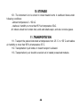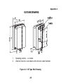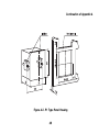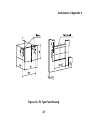
1
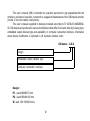
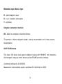
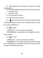
109456, Moscow,
1st Veshnyakovsky Avenue, 2
tel.: (095) 1748282, 1710921
R.No251 Order No 542
CI8
Counter of Impulses
User’s Manual
CONTENTS
Introduction..................................................... ......................................................................2
1.Designation.........................................................................................................................4
2.Technical Specification and Operation Conditions ...................................................5
3.Construction and Principle of Operation......................................................................8
4.Safety Measures.............................................................................................................29
5.Installation of the Instrument on Site and Prestarting Procedure...............................30
6.Instrument Operation Modes........................................................................................31
7.Maintenance......................................................................................................................43
8.Marking.............................................................................................................................43
9. Packing ............................................................................................................................43
10.Storage............................................................................................................................44
11.Transportation ..............................................................................................................44
Appendix A.Outline Drawing.............................................................................................45
Appendix B. Connection Diagrams....................................................................................48
Приложение В.Programmable Parameters..................................................................50
List for Changes Registration ............................................................................................54
1
This user’s manual (UM) is intended for operation personnel to get acquainted with the
structure, principle of operation, construction, usage and maintenance of the CI8 impulse counter
(further in the text called «instrument»).
This user’s manual is applied to devices produced according to ТУ 427800146526536
02. CI8 devices are produced in various modifications that differ from each other by housing type,
embedded output devices type and availability of computer connection interface. Information
about device modification is ciphered in full symbolic notation code:
CI8 device Х.Х.Х
Design
Embedded output devices type
Computer connection interface
Design:
P1 panel 96×96×70 mm
P2 panel 96×48×100 mm
W wall 130×105×65 mm м
2
Embedded output devices type:
R electromagnetic relays
S n
p
n transistor optocouplers
T optotriacs
Computer connection interface:
RS device has computer connection interface.
The example of devices designation used in ordering documentation and in other products
documentation:
CI8P1.R.RS device.
This means CI8 device having panel installation housing with 96×96 ×70 mm dimensions,
electromagnetic relays as control devices and also RS485 connection interface.
Conformity certificate No 03.009.0103.
Measurement instrumentation assertion certificate RU.C.34.004.A No 20005.
3
1. DESIGNATION
1.1. Multipurpose programmable eightbit pulse counter IC8 is designed to count:
number of impulses coming to its inputs in direct and opposite direction and further conver
sion of this number into a physical value (using multiplication by given factor);
frequency and width of impulses coming to its inputs;
operating time;
average and aggregate fluid flow rate (together with impulse or frequency sensors).
1.2. This instrument has two embedded key type output devices, which perform on/off
switching of the external technological equipment when preset values are reached.
4
2. TECHNICAL SPECIFICATION
2.1. Technical specification of the counter is given in table 1.
Table 1
Item
Value
Power supply
Supply voltage
AC
DC
Power consumption
Inputs
Number of control inputs
Inputs low (active) voltage level
Inputs high voltage level
130...265 V
180...310 V
no more than 4 VA
3
from 0 to 0.8 V
from 2.4 to 30 V
Impulse counter specification
Number of counting bits
Maximum frequency of input impulses
Minimum width of input impulses Range of predivider
values
Range of factor values
Time constant of input filter
5
7
8000 Hz
0.1 ms
1...9999
0.000001...9999999
0.1...1000 ms
Flow meter
Measuring time of average flow rate
1...99 s
Timing device
Timing discreteness
operating time counting mode
width measurement mode
Output devices
60 s
0.01 s
Maximum current commutated by relay contacts
Maximum current of transistor optocoupler load
Maximum current of optotriac load
Allowed load peak current of the second channel
doubling output
6
8 A at a voltage of 220 V and
cos ϕ > 0.4
0.2 A at a voltage of +50 V
50 mA at 300 V (constantly
open triac) or 1 A (triac at a
frequency not exceeding 50
Hz and timp = 5 ms)
30 mA (at a voltage +30 V)
Housing
Housing type
panel P1
Panel P2
Features
wall
Protection class
Overall dimensions, mm
IP44
IP54*
130x 105x 65
96x 96x 70
no more than 1,0 kg
Device mass
* Front panel side
2.2. This device is designed for operation in the following conditions:
Allowed ambient temperature +1... +50 Co
Relative air humidity (at temperature of +35 Co) no more than 80 %
Air pressure 86...107 kPa
7
IP20*
96x 48x 100
3. CONSTRUCTION AND PRINCIPLE OF OPERATION
3.1. Principle of operation
Functional diagram of the instrument is shown on figure 1. The device has three inputs for
external control signals which come to the inputs of data processing unit through input selector.
Figure 1
8
The data processing unit includes up/down impulse counter with a predivider at the input
and a multiplier at the output, timing device, average flow rate calculator, and also two logic devices
which generate control signals for output devices according to the userdefined algorithm.
3.1.1. The instrument has three inputs for external control signals connection. It’s possible
to connect to these inputs:
contacts of buttons, switches, relays, reed switches, etc. (figure 2);
active sensors with n
p
n open collector transistor at the output. To feed such sen
sors a voltage of +24±3 V (100 mA maximum load current) is provided on a terminal block of
the device (figure 3);
sensors of other types with high level output voltage from 2.4 to +30 V and low level output
voltage from 0 to 0.8 V (figure 4). Input current at low level voltage does not exceed 15 mA.
Figure 1
Figure 2
9
Figure 3
3.1.2. Counter of impulses is used to count pulses coming to its inputs.
3.1.2.1. The counter has three inputs with active low level.
Figure 5.
Each impulse coming on input «Count +» increments, and each impulse coming on input
«Count » decrements counter state by one. In case of impulses present simultaneously on both
inputs the counter state remains constant (figure 5). «Reset» input is destined to put the counter
into initial state.
On reset counter of impulses is loaded with a value set in Strt parameter (figure 6). If the
count should start from zero, it is necessary to set Strt parameter to zero.
Figure 6.
10
3.1.2.2. Fin.L and Fin.H parameters set ow and
high limits of the count, at which counter is automati
cally reloaded with the value set in Strt parameter
(figure 7). Fin.L value should be less and Fin.H value
should be more than Strt value.
3.1.3. Predivider at the counter of impulses input
Figure 7.
is used to divide input impulses frequency by the value
set in P parameter. The division is carried by means of «resampling down» impulses coming to
predivider input, i.e. impulse on predivider output is formed only after the number of impulses
coming to its input will reach the value set in P parameter.
The P parameter can possess only the integer values from 1 to 9999.
If input impulses come to both inputs of the predivider, then the impulse on its correspond
ing output is formed at the moment when the difference between number of impulses on input
«+» and input «» reaches P value.
Low level at the «Reset» input clears the predivider.
3.1.4. Multiplier at the «counter of impulses» output is used for conversion of the cumulative
number in the counter into a physical quantity (meters, litres, etc.) by means of multiplication by
the value set in F parameter. F value is set by user within the range from 0,000001 to 9999999. The
position of a comma at display of the physical quantity on indicator is defined by the position set
in F parameter.
11
3.1.5. Timing device is used for time intervals count and can work in one of two modes
set in Ftt parameter:
stop watch mode, which allows to measure time intervals from 0.01 s to 9 h 59 m 59.99
s at Ftt=0;
operating time counter mode, which allows to measure the aggregate device operating
time up to 99999 h 59 m at Ftt=1.
3.1.5.1. To control timing device there are two inputs with active low level: «Reset» and
«Lock».
Low level at «Lock» input pauses time count. Low level on «Reset» input stops time count
and clears the counter (figure 8).
3.1.5.2. In case of absence of active levels at control inputs time count starts right after
switching on the instrument. In case of power breakup the accumulated value is saved in nonvolatile
memory that allows to resume the interrupted count at the following switching on.
Figure 8.
12
3.1.6. Flow meter computes speed of physical quantity (meters, litres, etc.) variation over
a period of time set in ti parameter.
If F, P and ti parameters are set to 1 then flow meter shows the number of impulses coming
to counter input during 1 second, i.e. frequency.
The state of flow meter is updated in a measuring period ti.
In some oscillatorytype transducers some initial frequency corresponds to zero value of
the flow rate. Therefore the meter readings correction is required. The correction value can be set
by the user in di parameter.
3.1.7. Input commutator carries out commutation of instrument inputs to the data
processing unit inputs, and also preliminary conversion of signals. The input commutator
operation mode is defined by inP parameter.
3.1.7.1. Input filter is used to protect instrument inputs from contact bounce and from other
disturbances with duration less than the width of the friendly signal impulses. Input filter time
constant is set in tc parameter with discreteness of 0.1 ms. The minimum width of impulses
perceived by the instrument can be set from 0.1 to 999.9 ms (figure 9).
13
Figure 9.
For example, the highest frequency of input impulses at tc=0.1 equals to 5 kHz
because minimum period is 0.2 ms. Maximum count frequency 8 kHz can be obtained by
setting tc parameter to 0.0.
14
3.1.7.2. Countdown
of impulses with a possi
bility of lock and reset by
separate inputs is set at
inP=1 (figure 10).
Figure 10. Countdown of impulses with a possibility of
lock and reset by separate inputs
15
3.1.7.3. Countup of
impulses with a possi
bility of lock and reset
by separate inputs is
set at inP=2 (figure 11).
Figure 11. Countup of impulses with a possibility of lock
and reset by separate inputs
16
3.1.7.4. Up/down
count with
independent
«count+» and «count» in
puts and external reset is
set at inP=3 (figure 12).
Figure 12. Up/down count with independent count
inputs.
17
3.1.7.5. Up/down
count with external re
set and direction set by
external signal is set at
inP=4 (figure 13).
Figure 13. Up/down count with common count input,
count direction set by external signal and external reset
18
3.1.7.6. Up/down count with
automatic determination of the
direction from three sensors is set
at inP=5.
In this mode input commutator
automatically sets count direction
basing on queue of entering impulses
to the counter of impulses inputs (fig
ure 14), therefore impulse count starts
from the second impulse after the
counter reset. After setting of count
direction, commutator transmits all
impulses either to «+» or «» input of
the data processing unit. In this mode
it is impossible to lock count, and it’s
necessary to carry out
special
operating sequence to reset counter
of impulses (see 6.1.11).
Figure 14. Up/down count with automatic
determination of the direction from three
sensors
19
3.1.7.7. Countup with
lock and reset of the
counters of impulses and
timing devices is set at inP=6.
It is the only mode where
it is possible to perform exter
nal control of the timing de
vice. Input 3 is connected to
«Reset» inputs of timing de
vice and counter of impulses
simultaneously, and Input2 is
connected to «Lock» inputs.
Impulses entering Input1 of the
instrument are applied to «+»
input of data processing unit
(figure 15).
Figure 15. Countup with lock and reset of the counters
of impulses and timing devices
20
3.1.8. Power controller is intended to generate a signal at which the counters save
information about their current state in nonvolatile memory.
Owing to this it is possible to continue interrupted process without loss of information at the
restoration of supply.
Restoration of impulses counter value may be disabled by setting init parameter to 1. Then
the counter of impulses will be set to the initial state at restoration of supply.
3.1.9. Logic devices (LD) are intended to compare the current value of the controlled
parameter with preset values and to generate control signals for output devices according to given
algorithm. The instrument is equipped with two logic devices. It’s possible to apply to the input
of each logic device one of the following:
current value of a physical quantity,
flow meter state,
timing device state.
The source is set in SEL1 and SEL2 parameters accordingly:
«1» value of a physical quantity,
«2» flow meter state,
«3» timing device state.
21
3.1.9.1. The algorithm used by LD to control appropriate output device is set in SEt1 and
SEt2 parameters. Following variants are possible:
«1» – switched on at values less than U1 set point(U3)
«2» switched on at values not less than U1 set point(U3)
«3» switched on at values equal to U1 and U2 set points (U3 and U4), or values between
them;
«4» – switched off at values equal to U1 and U2 (U3 and U4) set points, or at values between
U1 and U2 (U3 and U4) set points;
«5» it is switched on for t1 (t2) time on reaching U1 (U3) set point;
«6 *» it is switched on for preset t1 (t2) time at a number multiple to U1 (U3) set point;
«7 *» it changes state for opposite at a number multiple to U1 (U3) set point.
* not available for timing device.
Besides, in dir1 and dir2 parameters the direction of controlled value variation is set, at which
LD should check conditions, set in parameters SEL1 and SEL2:
«1» check only at increase of current value
«2» check only at decrease of current value
«3» check in any case.
22
3.1.10. Types of output devices
Control output devices connected to the logic
may be realized as relays, optocouplers or
optotriacs. These devices perform on/off con
trol of the load either directly or through pow
erful control devices such as starters, solid
state relays, thyristors or triacs. All the output
elements are galvanically isolated from the
Figure 16.
instrument circuitry.
3.1.10.1. Transistor optocoupler is used, as a rule, to control lowvoltage (up to 50 V) re
lay. Connection diagram is given in figure16.
It is necessary to install diode VD1 (of КД103 type or similar) in parallel with the relay winding
to prevent transistor breakdown from high current of selfinduction.
3.1.10.2. Optotriac is included in the
control circuit of a powerful triac through
limiting resistor R1 as shown on figure17.
Ohmage of the resistor defines the triac
control current.
Figure 17.
23
Optotriac can also control a pair of
inverseparallel connected thyristors (see fig
ure18).
It is recommended to connect filtering
RC chains to the terminals of thyristors or
triacs to prevent them from breakdown caused
by highvoltage surges in the electric mains.
Figure 18.
3.1.10.3. The second channel of the instrument has doubling output transistor optocoupler
intended to control other similar devices (for example, the same counters, timing devices, etc.)
(figure19).
3.1.11. Operation modes of indication
3.1.11.1. Eightbit digital indicator constantly
displays one of the following values according to
the user’s choice:
state of the counter of impulses;
flow meter state;
timing device state;
U1 value;
Figure 19.
U3 value.
24
3.1.11.2. Parameter ind is used to select the value to be constantly displayed on the
indicator. It is possible to view other two values by pressing and holding of
or
button.
Ind
Constantly displayed source
The first shadow
source
button
1
counter of impulses
flow meter
2
flow meter
3
timing device
timing device
counter of impulses
The second shadow
source
button
timing device
counter of impulses
flow meter
4
U1 value
-
-
5
U3 value
-
-
Note At the values of parameter Ind = 4 or Ind = 5 a brief pressing of the
button makes
it possible to proceed to changing of the set point displayed on indicator. Repeated pressing of
the
button saves new value.
3.1.12. Connection interface RS485 is used to monitor instrument indications on a
computer. The address of the instrument is set in parameter Adr, and its digit capacity is set in A.LEn
parameter. At A.LEn = 8_bit the address is eightbit and its value is within the range from 0 to 255.
At A.LEn = 11_bit the address is elevenbit and its value is within the range from 0 up to 2047.
25
Data exchange rate (from standard scale) is set in SPd parameter and can possess values
from 2400 to 57600 bps.
Data format is set in For parameter and it can be of the following types:
For
7b_nP_2S
Data digit capacity, bit
7
Evenodd check
Stopbit number
no
2
7b_EP_1S
7
even
1
7b_EP_2S
7
even
2
1
7b_OP_1S
7
odd
7b_OP_2S
7
odd
2
8b_nP_1S
8
no
1
8b_nP_2S
8
no
2
8b_ЕP_1S
8
even
1
8b_ОP_1S
8
odd
1
26
3.2. Instrument structure
This instrument is embodied in plastic housing
designed for panel or wall mount. Sketches of housings
with overall and mounting dimensions are shown in Ap
pendix A.
3.2.1. All parts of the instrument are installed on
two printedcircuit boards. There is a control keyboard,
digital indicator and light emitting diodes on one board
and a power module and connecting terminal on another
one.
3.2.2. Fastenings are included in supply for panel
mounting of the instrument.
3.2.3. Terminal block for external connections is
installed on the back panel. In the instruments designed
for the wall installation this terminal is mounted inside
the instrument, and rubber gaskets are placed in the
holes for external connections
3.2.4. The view of instrument front panel for wall
and panel (P1) types of housing is shown on figure 20
and for panel housing (P2) on figure 21. Indication and
control elements are arranged on the front panel.
Figure 20.
Figure 21.
27
3.2.4.1. Eightbit digital indicator is used for display of counting value or instrument
functional parameters.
3.2.4.2. Four red light emitting diodes signal about count direction and output devices state:
«+» count direction is direct;
«» count direction is reverse;
«К1» the first output device is switched on;
«К2» the second output device is switched on.
3.2.4.3.
button is used to enter the mode of view and set up of operation parameters,
for setting parameter value after its selection, and also for saving the new set value in nonvolatile
memory and exit to OPERATION mode.
3.4.2.4.
button is used:
in OPERATION mode to view the first shadow source by holding it;
in PROGRAMMING mode to select parameter from the list, change sign of a number or
its value by pressing it.
3.4.2.5.
button is used:
in OPERATION mode to view the second shadow source by holding it;
in PROGRAMMING mode to go to parameter that carries out return to «Parameters groups
menu» or to OPERATION mode, or to go to setting of comma position for factor value or selection
of digit position while setting the parameter value.
28
4. SAFETY MEASURES
4.1. The instrument protection class from electric shock conforms to the class 0 of State
Standard (GOST) 12.2.007.075.
4.2. The instrument uses dangerous voltage. It is necessary to disconnect the instrument
and all devices connected to it from the mains before any repair or maintenance operations.
4.3. Do not allow ingress of moisture on the terminal block output contacts and internal
electric parts of the instrument. It is forbidden to use the instrument in hostile environment
containing acid, alkali, oil, etc.
4.4. Only qualified personnel who’s familiar with the user’s manual is allowed to perform
connection, adjustment and maintenance of the instrument.
4.5. While use and maintenance it is necessary to comply with demands of State Standard
(GOST) 12.3.01980, «Operation Rules for Consumer’s Electrical Installations» («Правил
эксплуатации электроустановок потребителей») and «Labor Protection Rules for Using the
Consumer’s Electric Installations» («Правил охраны труда при эксплуатации электроустановок
потребителей»).
ATTENTION! As there is a dangerous voltage on the terminal block, the instruments in
housings for panel mounting (P1 and P2 modifications) must be installed in control boards
accessible only to qualified personnel.
29
5. INSTALLATION OF THE INSTRUMENT ON SITE AND PRESTART
ING PROCEDURE
5.1. Install the instrument on a regular place and anchor it using assembly fasteners
included in supply. Overall and mounting sizes of the instruments in different housings are given
in Appendix A. Schemes of connection are given in Appendix B.
5.2. Install connection links for control signals, connections of the instrument with power
network and actuators. It is necessary to use only standard instruments for installation operations.
5.3. While mounting external connections it is necessary to provide reliable contact with
instrument terminals, so it is recommended to clean carefully and to tin their contacts.
Conductors crosssection must not exceed 1 mm2. Connection of wires in all types of
housings is carried out by means of screw. To access terminal block of the instrument in the wall
mount housing it is necessary to remove its upper cover.
5.4. It is forbidden to merge output 14 (common) of the instrument with equipment
grounding. It is not permitted to install control signals wires in one bundle with power cables
producing highfrequency or pulse disturbances.
5.6. Switch on the instrument after making all necessary connections. «0» will be displayed
on the digital indicator.
5.7. Set all necessary operation parameters following corresponding instructions (see
section 6.1).
30
6. INSTRUMENT OPERATION MODES
The instrument can be used in one of two modes:
OPERATION or PROGRAMMING.
6.1. Programming
6.1.1. PROGRAMMING mode is used to change and save in nonvolatile memory the
instrument parameters, necessary for operation.
Preset values are saved in the instrument nonvolatile memory at switching off.
6.1.2. Programmed parameters are divided into groups according to their designation.
Parameters list and their description are given in Appendix B.
6.1.3. Each group includes parameters SEc and out.
SEc parameter is intended to guarantee protection from unauthorized change of param
eters value. When SEc=1, access to the PROGRAMMING mode is possible only through a special
code, corresponding to the current group. If invalid code is entered, only view of preset values
is possible. At SEc=0 change of parameters without entering the code is enabled.
Access to parameter SEc irrespective of its value is possible only at the entering the group
through the code.
out parameter is used to exit group and to go to top level menu. Selection of desired
parameter inside the group is performed with the button
, to go to out parameter press the
button
.
31
To display on the indicator current value of selected parameter press
button.
6.1.4. Top level menu contains a list of parameter group names:
«GrouP_A», «GrouP_b», «GrouP_C», «GrouP_d», «GrouP_E», and also the names of
operations:
reset of the counter of impulses c.rES and
reset of the timing device t.rES.
6.1.5. To enter top level menu in OPERATION mode press and hold
button until c.rES
appears on digital indicator (figure 22).
Select desired group of parameters or operation using
button. out parameter is used
to exit from menu back to OPERATION mode. Pressing
button makes it possible to go to out
parameter from any menu item.
Press
button. If out was selected then the instrument will return to OPERATION mode.
Otherwise an invitation appears on the digital indicator to enter access code «Pln_0000».
Enter the code if necessary, and press
button. While entering the code use button
to select its digit position and
button to set its value.
32
33
Figure 22.
6.1.6. «GrouP_A» group (figure 23) contains set
points for logic devices U1, U2 (t1), U3 and U4 (t2).
Decimal point position in parameters U1, U2, U3 and U4
is defined by its position in F parameter.
To set the values of U1, U2, U3 and U4 parameters:
set parameter sign using
button (at positive
value corresponding digit is blank, at negative value sign
«» is blinking);
then select digit for changing using button
(selected
digit is blinking);
set its value using
button;
press
button to return to the group menu.
If LD uses t1 and t2 parameters instead of U2 and
U4, set their values in the range from 1 to 99 s.
Figure 23.
34
To set t1 and t2 parameters values:
select digit for changing using button
;
set its value using
button;
press
button to return to the group menu.
6.1.7. «GrouP_b» group (figure 24) contains
Fin. L, Fin. H parameters that set count limits and
Strt value loaded in the counter of impulses when
these limits are reached. Decimal point position in
these parameters is defined by its position in F
parameter.
To set Fin. L, Fin. H and Strt parameters
values:
set parameter sign using
button (at
positive value corresponding digit is blank, at
negative value sign «» is blinking);
select digit for changing using button
;
set its value using
button;
press
button to return to the group
menu.
At setting of Strt parameter value button
is used not only to select necessary digit, but
also to set oFF value.
35
Figure 24.
6.1.8. «GrouP_C» group (figure 25) contains inP and tc parameters that define operation
mode of the input commutator, coefficients of predivider P and multiplier F, measuring time ti
and initial bias di for flow meter, and also operation modes of timing device Ftt, indication ind
and reset of counter of impulses at switching on the instrument init.
Figure 25.
36
To set coefficient of predivider P value:
select digit for changing using
button;
set its value using
button;
press
button to return to the group menu.
To set coefficient of multiplier F value:
set comma position using
button and press
setting;
select digit for changing using
button;
set its value using
button;
press
button to return to the group menu.
To set flow rate measuring time ti:
select digit for changing using
button;
set its value using
button;
press
button to return to the group menu.
37
button to go to digitbydigit value
To set initial bias for flow meter di:
set bias sign using
button (at positive value corresponding digit is blank, at negative
value sign «» is blinking);
select digit for changing using
set its value using
button;
button;
press PROG. button to return to the group menu.
To set parameters inP, ind and Ftt, Init values:.
set each value using
press
button;
button to return to the group menu.
6.1.9. «GrouP_d» group (figure 26) contains SEL1 and SEL2 parameters that define input
values for LD1 and LD2, SEt1 and SEt2 parameters that define their operation logic and dir1, dir2
parameters that define count direction at which output devices must act.
To set SEL1, dir1, SEt1, SEL2, dir2 and SEt2 parameters values:
set each value using
press
button;
button to return to the group menu.
38
6.1.10. «GrouP_E» group (figure 27) is used to set instrument network address Adr, its digit
capacity A.LEn, data exchange rate SPd and sending format For (if RS485 interface is present).
Figure 26.
39
To set A.Len parameter value:
set its value using
press
button;
button to return to the group
menu.
To set Adr parameter value:
select digit for changing using
set its value using
button;
press
button;
button to return to the group
menu.
To set SPd parameter value:
For this purpose:
set its value using
button;
press
button to return to the group
menu.
To set For parameter value:
For this purpose:
select format using
button;
press
button to return to the group menu.
Figure 27.
40
6.1.11. c.rES group (figure 28) is
used to reset counter of impulses (the
predivider thus is zeroed).
On entering the group parameter
rESEt appears. To reset the counter
press
button.
Reset progress is accompanied
by consecutive flare of points on the
indicator.
If protection against unauthorized
reset is used (parameter SEc=1) then
rESEt parameter is accessible only af
ter entering the code. Otherwise param
eter out, which will be the only one in the
group, is displayed on the indicator.
Figure 28.
41
6.1.12. «t.rES» group (figure 29)
is used to reset timing device, for exam
ple in case of use of the instrument as
the operating time counter.
On entering the group parameter
CLEAr appears. To reset the counter
press
button. Reset progress is
accompanied by consecutive flare of
points on the indicator.
If protection against unauthorized
reset is used (parameter SEc=1) then
CLEAr parameter is accessible only after
entering the code. Otherwise parameter
out, which will be the only one in the
group, is displayed on the indicator.
6.2. OPERATION Mode
In OPERATION mode the instru
ment displays measured value, which
represents the result of input actions
and generates signals according to the
algorithm preset at programming.
Figure 29.
42
7. MAINTENANCE
Maintenance of the instrument should be carried out at least once in six months and includes
instrument fastening check, electric connections check, and also removal of the dust and debris
from instrument terminal.
8. MARKING
8.1. The instrument is marked with:
symbolic notation code of instrument type and modification;
trade mark of the manufacturer;
serial No;
year of manufacturing.
9. PACKING
9.1. Instrument packing is carried out in accordance with State Standard (GOST) 918174
using market container made from corrugated board.
9.2. Products packing for mail delivery is carried out in accordance with State Standard
(GOST) 918174.
43
10. STORAGE
10.1. The instrument is to be stored in closed heated rooms in cardboard boxes under
following conditions:
ambient temperature 0...+60 єC.
relative air humidity no more than 95 % at temperature 35єC.
Air indoors should not contain dust, acids and alkalis vapor, and also corrosive gases.
11. TRANSPORTATION
11.1.
air humidity
11.2.
11.3.
Transport the packed instrument at temperature from 25 °C to +55 °C and relative
no more than 95 % at temperature 35 °C.
Transportation by all kindss of closed transport is allowed.
Transportation by air should be carried out in heated pressurized modules.
44
Appendix A
OUTLINE DRAWING
1.
2.
Operating position – no matter
Undercut barrels in accordance with entrance cable diameter
Figure A.1. W Type Wall Housing
45
Continuation of Appendix A
Figure А.2. P1 Type Panel Housing
46
Continuation of Appendix A
Figure A.3. P2 Type Panel Housing
47
Appendix B
Figure B.2. Connection of the CI8
instrument with optotriac output
Figure B.1. Connection of the CI8
instrument with relay output
48
Continuation of Appendix B
Figure B.3. Connection of the CI8
instrument with optical transistor output
49
Appendix C
Programmable parameters
Name
Parameter
Description
Values
Default valu User’s value
General parameters (present in each group)
Return to main menu from
PROG. button
out
parameters group in
[command]
programming mode
SEc
Possibility of parameters
change
0 or 1
rESEt
Counter of impulses reset
PROG. button
0
[command]
CLEAr
Сброс счетчика времени
Group_A. LD settings
U1
LD1 first setting
9999999...9999999
U2
LD1 second setting
9999999...9999999
U3
U4
LD2 first setting
LD2 second setting
9999999...9999999
9999999...9999999
0
* «User’s value» column is filled in during instrument programming
50
0
Continuation of Appendix C
1
t1
2
3
First output device on state time
1...99 s
Second output device
1...99 s
on state time
Group_b. Counter of impulses load parameters
Counter of impulses
Strt
9999999...9999999
initial value
t2
FinL
Low bound of count, at which
ounter of impulses is reloaded
Upper bound of count, at which
FinH counter of impulses is reloaded
4
0
9999999...Strt1
10
Strt+1... 9999999
10
Group_С. Counter of impulses load parameters
P
Divider (coefficient needed for
predivider operation)
1...9999
1
F
Factor (coefficient needed for
multiplier operation)
0.0000001...9999999
1
Ti
Consumption measuring time
1...99 s
51
0.75
5
Continuation of Appendix C
1
2
3
4
5
di
Flow meter indication bias
0.0000001...9999999
0
inp
Instrument inputs designation
1...6
4
tc
Input filter time constant
0.1...999.9 ms
20.0
ind
Parameter displayed on
indicator
1...5
1
Ftt
Format of time displayed on
indicator
0 or 1
1
init
Counter of impulses reload
with Strt parameter value at
instrument switching on
0 no
0
1 yes
Group_d. Logic devices operation parameters
SEL1
dir1
Input value for LD1
Count direction when LD1
functions
52
1...3
1
1...3
1
Continuation of Appendix C
1
2
SEt1
Control algorithm for the first
output device
SEL2
3
Input value for LD2
1...3
4
1
Count direction when LD2
functions
1...3
2
Control algorithm for the sec
ond output device
Group_E. PC connection parameters
1...7
1
dir2
SEt2
A.Len
Adr
Spd
Instrument address length
Instrument network address
Data rate
For
Data format
8_bit or 11_bit
0...256 or 0...2048
2400...57600 bps
8_bit
0
9600
see 3.1.12
7b_nP_2S
53
5
LIST FOR CHANGES REGISTRATION
Change
No
1
annuled
Lists total
(pages)
Date of
change
Signature
new
4
5
6
7
8
List No (pages)
changed substituted
2
3
54