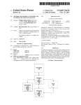
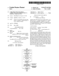
1
USOO8715031B2
(12) United States Patent
(10) Patent N0.:
Fong et a].
(54)
(45) Date of Patent:
4,717,364 A
1/1988 Furukawa
SOUND_BASED ACTION
4,840,602 A
4,949,327 A
6/1989 Rose
8/1990 Forsse et al.
SYNCHRONIZATION
5,145,447 A *
Inventors: Peter Sui Lun Fong, Monterey Park, CA
9/1992
Notice:
(US); Xi-Song Zhu, ShenZhen (CN);
6,514,117 B1
2/2003 Hampton et a1.
6,609,979 B1 *
8/2003 Wada ~~~~~~~~~~~~~~~~~~~~~~~~~~~~ ~~ 463/43
CA (Us)
6,682,392 B2
7,120,257 B2
* cited by examiner
Aug. 6, 2009
Prior Publication Data
Int. Cl.
A63H 30/00
(52) us CL
Assistant Examiner * Alex F. R. P. Rada, II
’
(74) Attorney, Agent, or Firm * Stetina Brunda Garred &
(51)
(56)
......................... .. 446/268
Primary Examiner * William Brewster
Feb 10 2011
'
Zh
Elan Microelectronics C0111, “User’s Manual” D00 VefSiOIl 13,
MW 2007
MacroniX International Co., Ltd. “MXIC” Oct. 13, 2005.
Elan Microelectronics Corp., “Reference Guide” Doc. Version 1.3,
(22)
Us 2011/0034103 A1
6/2008
eng
OTHER PUBLICATIONS
ch~ 2007
(65)
1/2004 Chan
10/2006 Mahoney
2008/0139080 A1*
(21) App1.No.: 12/536,690
(58)
t l.
Kelvin Yat-Kit Fong, Monterey Park,
Subject to any disclaimer, the term of this
patent is extended or adjusted under 35
U_S_C_ 154(b) by 1279 days_
Filed:
Goldfarb ..................... .. 446/408
12/1996 Nakad
6,312,307 B1 * 11/2001 Dean, i116”? .................. .. 446/297
(73) Assignee: Peter Sui Lun Fong, Monterey Park, CA
(US)
(*)
May 6, 2014
INTERACTIVE DEVICE WITH
5,587,545 A *
(75)
US 8,715,031 B2
Brucker
(2006.01)
(57)
ABSTRACT
USPC ------------- -- 446/ 175; 446/297; 446/484; 463/ 1;
An interactive amusement device and a method therefor are
463/7; 463/30; 463/43
Field Of ClaSSi?catiOIl SeaI‘Ch
USPC ---------------- -- 463/1, 7, 30*31, 4(L43; 434/118,
_ _
434/307 R; 446175, 297: 484
disclosed. The device plays a musical soundtrack in a ?rst
game iteration corresponding to a learning mode. A sequence
of user input actions received during this learning mode is
detected, and timestamps for each is stored into memory. In a
see apphcanon ?le for complete searCh hlswry'
R f
Ct d
second game iteration corresponding to a playback mode, the
musical soundtrackis replayed.Additionally, an output signal
U.S. PATENT DOCUMENTS
is generated on at least one interval of the user input actions
based on the stored timestamps, and is coordinated With the
e erences
4,245,430 A
4,272,915 A
1 e
replaying of the musical soundtrack.
1/1981 Hoyt
37 Claims, 13 Drawing Sheets
6/1981 Noble
I99
GENERATE
INSTRUCTIONAL
OOMMAND
200—/
PLAY MUSICAL SOUNDTRACK
<———————J
202 _/
DETECT SEQUENCE OF USER INPUT
ACTIONS
STORE TIMESTAMPS
FOR EACH OF THE
USER INPUT ACTIONS
I
DERIVE USER INPUT
ACTION TYPES FROM
RECEIVED SOUND
SIGNALS
STORE SOUND
SIGNALS OF
RECORDED USER
INPUT ACTIONS
I—
LEARNING MODE
205
PLAYBACK MODE
208/
REPLAY MUSICAL SOUNDTRACK
I
I
GENERATE OUTPUT
AUDIO SIGNAL BASED
0N TIMESTAMPS
I
210
I
ACTIVATE MECHANICAL
ACTUATORS BASED ON
TI MESTAM PS
I
212
ACTIVATE ANIMATION
BASED ON TIMESTAMPS
I
214
US. Patent
FIG. 1A
May 6, 2014
Sheet 1 0f 13
FIG. 1 B
US 8,715,031 B2
HQ. 1 C
US. Patent
May 6, 2014
Sheet 2 0f 13
US 8,715,031 B2
3” '\ POWER
SUPPLY
32
PROGRAMMABLE
DATA PROCESSOR
28
ZQ
34 JO
38
I
40 /‘
MEMORY
FIG. 2
41
44
46
MUSICAL SOUNDTRACK—>
START PLAYBACK
OF MUSICAL
END PLAYBACK
OF MUSICAL
SOUNDTRACK/
SOUNDTRACK/
ACTIVATE
ACOUSTIC
TRANSDUCER
DEACTIVATE
ACOUSTIC
TRANSDUCER
FIG. 4
US. Patent
May 6, 2014
Sheet 3 0f 13
US 8,715,031 B2
1,99
GENERATE
INSTRUCTIONAL
COMMAND
200_/
PLAY MUSICAL SOUNDTRACK
202 /
DETECT SEQUENCE OF USER INPUT
ACTIONS
¢
<-—-—--J
¢
v
DERIVE USER INPUT
206
(
STORE SOUND
SlggEElmlEgmmgs
ACTION TYPES FROM
SIGNALS OF
USER INPUT ACTIONS
RECEIVED SOUND
SIGNALS
RECORDED USER
INPUT ACTIONS
I
I
I
204
I
I
LEARNING MODE
............................... y
208/
PLAYBACK MODE
REPLAY MUSICAL SOUNDTRACK
I
v
GENERATE OUTPUT
ACTIVATE MECHANICAL
AUDIO SIGNAL BASED
ACTUATORS BASED ON
ON TIMESTAMPS
TIMESTAM PS
I
Biggg'gT??wysiT/lms
I
210
212
FIG. 3
214
US. Patent
May 6, 2014
4
8550
US 8,715,031 B2
Sheet 6 0f 13
3%(29
8550
US. Patent
May 6, 2014
Sheet 7 0f 13
US 8,715,031 B2
80a
58
62
FIG. 6
US. Patent
May 6, 2014
Sheet 9 0113
US 8,715,031 B2
1 NC
N0 .51.
13
NC
NC 4
PD4
MICPOWER
12
NC U2 NC 5
PB?
MICIN
FD?
BZPOWER
40 ~—:-__~
lL NC
1° vss
9
NC
—
NC 6—
7
PMZ
Q a
PA14
s
_%_
SPKD]: :22
PBG-
l
FAB
,
1
PM
|
|
PAS
'
|
PM
26
_/__“
2
D
ID
PA? \\
3
a:ml 00‘E m“I mll a:El q20; "-I2 an“.
I
w “I 2 2 g g; g g
i
J'
A
1
28
‘
31' 2 Q Q 9 > > :
1
E
MIC POWER
R13
521
9015c
08
5.6K 2:
Piezo
Transducer
+
=°"*
7
m $150
-
Ema: IN >
m
R24
012
104
@110
FIG. 7B
US. Patent
|
:
May 6, 2014
Sheet 10 0f 13
vcc
‘
A
U5
l l: C16
I
II
I
US 8,715,031 B2
/~ 70
Driver
220uF
1" C1? T:
___ IBATI'
220uF
l
l
L—
|
:
I
_
vcc
A
I
|
i
U4
IR receiver
1
10k ©
K
R25
?
'3:
Eggl'RANSMITTER
I
|I
'
i
I
R19
R25
1K
Il—
1/ QB
9013H
5:015
100uF
10
:
R27
am
FIG. TC
011
9013H
US. Patent
FIG. 9A
May 6, 2014
FIG. QB
Sheet 12 0f 13
FIG. 9C
US 8,715,031 B2
FIG. 9D
US. Patent
May 6, 2014
Sheet 13 0f 13
POWER ON
300
SLEEP MODE
302
NO
US 8,715,031 B2
304
BUTTON
PRESSED?
RETURN TO
SLEEP MODE
302
YES
+
306/
CLEAR ALL REGISTERS
ENTER DEMONSTRATION MODE
I
+
318
YES
316
308
I
ENTER LEARNING MODE
DEACTIVATE TRANSDUCER
USER INPUT
DETECTED?
<—NO
REGISTER_O > 2?
*‘310
NO-—--->
INCREMENT REGISTER_O
I
314
YES
V
CLEAR REGISTERWO
’32!)
I
ENTER PLAYBACK MODE
r322
I
INCREMENT REGISTER_1
$324
RETURN TO
SLEEP MODE
CLEAR ALL REGISTERS
I
328
302
US 8,715,031 B2
1
2
INTERACTIVE DEVICE WITH
SOUND-BASED ACTION
SYNCHRONIZATION
Instead of mechanical activation, the child provided a voice
command to the doll. The received audio signal was pro
cessed by a voice recognition engine to evaluate what com
CROSS-REFERENCE TO RELATED
APPLICATIONS
mand was issued. Based upon the evaluated command, a
response was generated from a vocabulary of words and
phrases stored in memory. A central processor controlled a
speech synthesizer that vocalized the selected response. In
conjunction with the vocalized speech, an accompanying
Not Applicable
STATEMENT RE: FEDERALLY SPONSORED
RESEARCH/ DEVELOPMENT
10
musical soundtrack could be generated by an instrument syn
thesizer. The central processor could also control various
motors that were coupled to the features of the doll in order to
simulate life-like actions.
These animated toys typically portrayed popular charac
Not Applicable
ters that appeared in other entertainment modalities such as
BACKGROUND
1. Technical Field
The present invention relates generally to toys and amuse
ment devices, and more particularly, to an interactive toy with
sound-based action synchronization.
20
2. RelatedArt
dolls, there remain a number of de?ciencies. Some parents
and child psychologists argue that these dolls do nothing to
stimulate a child’s imagination because they are reduced to
Children are often attracted to interactive amusement
devices that provide both visual and aural stimulation. In
recognizing this attraction, a wide variety have been devel
oped throughout recent history, beginning with the earliest
25
“talking dolls” that produced simple phrasings with string
activated wood and paper bellows, or crying sounds with
weight activated cylindrical bellows having holes along its
side. These talking dolls were typically limited to crying
“mama” or “papa.”
television shows and movies, and accordingly appeared and
sounded alike. Some commercially available toys with these
interactive features include Furby® from Hasbro, Inc. of
Pawtucket, RI. and Bamey® from HiT Entertainment Lim
ited of London, United Kingdom.
Despite the substantially increased interactivity with these
30
Further advancements utilized wax cylinder phonograph
recordings that were activated with manually wound clock
reacting passively to a toy, much like watching television.
Notwithstanding the increased vocabulary, the limited num
ber of acceptable commands and responses has proven inter
action to be repetitious at best. Although children may ini
tially be fascinated, they soon become cognizant of the
repetition as the thrill wears off, and thus quickly lose interest.
Accordingly, there is a need in the art for an improved amuse
ment device. Furthermore, there is a need for interactive toys
with sound-based action synchronization.
work-like mechanisms. Various phrases were recorded on the
phonographs for playback through the dolls to simulate dia
logue. Still popular among collectors today, one historically
BRIEF SUMMARY
35
signi?cant embodiment of a talking doll is the “Bebe Pho
One embodiment of the present invention contemplates an
nographe” made by the Jumeau Company in the late 19th
amusement device that may include a ?rst acoustic transducer
and a second acoustic transducer. Additionally, the amuse
ment device may include a programmable data processor that
century. In addition to spoken words, music was also recorded
on the phonograph so that the doll could sing songs and
nursery rhymes.
40
Thereafter, dolls having an increased repertoire of ten to
and an output port connected to the second acoustic trans
twenty spoken phrases were developed. The speaking func
tion was activated with a pull of a string that activated a
miniature phonograph disk containing the pre-recorded
phrases. The “Chatty Cathy” talking doll includes such a pull
string-activated mechanism.
45
In addition to the aforementioned speaking capabilities,
invention, a method for interactive amusement is contem
soundtrack in a ?rst game iteration that corresponds to a
50
be correspondingly moved. The instructions required for such
synchronized animation of the features of the doll were stored
in a cassette recording with the control signals and the audio
signal.
55
sponds to a playback mode. Further, the method includes
generating in the playback mode an output audio signal on at
least one interval of the received sequence of user input
60
ments involved dolls with basic sensors such as piezoelectric
improvements in digital data processing and storage, how
ever, dolls having greater interactivity became possible.
input actions. The timestamps may be synchronized to the
musical soundtrack. The method may also include replaying
the musical soundtrack in a second game iteration that corre
limited to decidedly mechanical modalities such as pulling a
buzzers that, when triggered, cause the doll to respond imme
diately by outputting a sound or movement. Examples of such
devices include the “Interactive Sing & Chat BRUINTM Bear”
from Toys ‘R’ Us, Inc. of Wayne, N.J. With substantial
learning mode. Additionally, the method includes detecting a
sequence of user input actions received during the learning
mode. Then, the method continues with a step of storing into
memory timestamps of each of the detected sequence of user
One de?ciency with these earlier talking dolls was the
rather low degree of interactivity between the doll and the
child, as the input to trigger speaking and movement was
string, turning a crank, or pushing a button. Further improve
ducer. The programmable data processor may be receptive to
input sound signals from the ?rst acoustic transducer contem
poraneously with an audio track being output to the second
acoustic transducer.
In accordance with another embodiment of the present
plated. The method includes a step of playing a musical
there have been efforts to make a doll more lifelike with
movable limbs and facial features. Further, the movement of
such features was synchronized with the audio output. For
example, when a phrase was uttered, the jaws of the doll could
has an input port connected to the ?rst acoustic transducer,
actions based upon the recorded timestamps. The output
audio signal may be coordinated with the replaying of the
musical soundtrack.
According to another embodiment, an animated ?gure
amusement device is contemplated. The device may have at
65
least one movable feature. The amusement device may
include a ?rst acoustic transducer that is receptive to a
sequence of sound signals in a ?rst soundtrack playback
US 8,715,031 B2
3
4
iteration. The sequence of sound signals may correspond to a
pattern of user input actions associated with the soundtrack.
Additionally, the amusement device may include a mechani
cal actuator with an actuation element that is coupled to the
movable feature of the animated ?gure. The amusement
device may also include a programmable data processor that
has a ?rst input connected to the acoustic transducer, and a
?rst output connected to the mechanical actuator. The
mechanical actuator may be activated by the programmable
data processor in synchronization with the received sequence
of sound signals in a second soundtrack playback iteration.
presently preferred embodiment of the invention, and is not
intended to represent the only form in which the present
invention may be constructed or utilized. The description sets
forth the functions of the invention in connection with the
illustrated embodiment. It is to be understood, however, that
the same or equivalent functions and may be accomplished by
different embodiments that are also intended to be encom
passed within the scope of the invention. It is further under
stood that the use of relational terms such as ?rst and second,
top and bottom, left and right, and the like are used solely to
distinguish one from another entity without necessarily
requiring or implying any actual such relationship or order
between such entities.
With reference to FIG. 1A, one exemplary embodiment of
In a different embodiment, an amusement device is con
templated. The amusement device may similarly have a
replayable soundtrack. The amusement device may include a
?rst acoustic transducer that is receptive to a ?rst sequence of
sound signals in a ?rst soundtrack playback iteration. The
sequence may correspond to a pattern of user input actions
an interactive device 10 is an anthropomorphized rabbit FIG.
11 having a body section 12, a pair oflegs 14, a pair of arms
16, and a head 18. In further detail, the head 18 includes a pair
associated with the soundtrack. There may also be a program
mable data processor that has a ?rst input connected to the
?rst acoustic transducer, and a ?rst output connected to a
second acoustic transducer. A second sequence of sound sig
nals may be played by the programmable data processor in the
second soundtrack playback iteration. In this regard, the sec
ond sequence of sound signals may be synchronous with the
?rst sequence of sound signals.
The present invention will be best understood by reference
to the following detailed description when read in conjunc
tion with the accompanying drawings.
20
will be appreciated, the doll FIG. 11 may portray humans,
other animals besides rabbits such as dogs, cats, birds and the
like, or any other character real or imagined. It will also be
appreciated that the foregoing features of the doll FIG. 11 are
25
30
FIGS. 1A-C illustrate an exemplary embodiment of an
35
implemented;
40
FIG. 4 is a plot illustrating an exemplary signal of user
45
The block diagram of FIG. 2 best illustrates the functional
components of the interactive device 10. A programmable
data processor 26 is central to the interactive device 10, and is
50
con?gured to execute a series of preprogrammed instructions
that generates certain outputs based upon provided inputs.
wireless transceiver;
Speci?cally, the executed instructions are understood to be
steps in a method for interactive amusement according to one
FIG. 8 illustrates another exemplary embodiment of the
interactive device, including an on-board display device;
embodiment of the present invention. The pro grammable data
FIGS. 9A-9D are illustrations of an animation sequence
generated on the on-board display device.
11 are not limited to the head 18 and the ears 24, and any other
features may also be movable to simulate various actions
being performed by the doll FIG. 11.
FIG. 6 illustrates an alternative embodiment of an interac
tive device in use;
FIG. 7 is a schematic diagram of the alternative embodi
ment of the interactive device including a display driver and a
has a resting position as shown in FIG. 1A, an intermediate
position as shown in FIG. 1B, and an extended position as
shown in FIG. 1C. Those having ordinary skill in the art will
recognize that the movement of the features of the doll FIG.
input actions generated by an acoustic transducer;
FIG. 5 is a schematic diagram illustrating the embedded
systems components of the interactive device including a
central processor, a memory device, a pair of mechanical
actuators, and acoustic transducers; and
ears 24 are capable of rotating or “?apping” about the head
18. In further detail, FIG. 1A shows the ears 24 in a resting
position, FIG. 1B shows the ears 24 in an intermediate posi
tion, and FIG. 1C shows the ears 24 in an extended position.
As will be described in further detail below, the movement of
the ears 24 between the resting position, the intermediate
position, and the extended position simulate a clapping action
being performed by the doll FIG. 11. Similarly, the head 18
FIG. 3 is a ?owchart illustrating the method for interactive
amusement;
to the body section 12 along with actuators to move those
features. For example, as shown in FIGS. 1B and 1C, the head
18 is capable of pivoting about the body section 12, and the
respect to the following description and drawings, in which:
interactive device in various states;
FIG. 2 is a functional block diagram of the interactive toy
in accordance with one embodiment of the present invention,
whereupon a method for interactive amusement may be
presented by way of example only, and not of limitation.
It is contemplated that the various features of the doll FIG.
11 are animated, i.e., movable, and have appropriate under
lying support elements and joint structures coupling the same
BRIEF DESCRIPTION OF THE DRAWINGS
These and other features and advantages of the various
embodiments disclosed herein will be better understood with
of eyes 20, a mouth 22 and a pair of ears 24. Where appro
priate, each of the ears 24 will be referenced individually as
right ear 24a and left ear 24b, and collectively as ears 24. As
55
FIG. 10 is a detailed ?owchart illustrating one exemplary
processor 26 is understood to have an arithmetic logic unit,
various registers, an instruction decoder, and a control unit, as
software application being executed by the central processor
is typical of data processing devices. An internal random
to implement the interactive device according to an embodi
ment of the present invention.
Common reference numerals are used throughout the
drawings and the detailed description to indicate the same
elements.
access memory may also be included. By way of example, the
programmable data processor 26 is l6-bit digital signal pro
60
poration of Hsinchu, Taiwan, though any other suitable IC
devices may be readily substituted without departing from the
DETAILED DESCRIPTION
65
The detailed description set forth below in connection with
the appended drawings is intended as a description of the
cessing (DSP) integrated circuit. One commercially available
option is the eSL Series IC from Elan Microelectronics Cor
scope of the present invention.
The programmable data processor 26 has a plurality of
general-purpose input/output ports 28 to which a number of
peripheral devices are connected, as will be described below.
US 8,715,031 B2
5
6
The programmable data processor 26 is powered by a power
supply 30, which is understood to comprise a battery and
conventional regulator circuitry well known in the art.
According to one embodiment, among the input devices con
memory module 40 is the MX25L3205D device from
Macronix International Co., Ltd. of Hsinchu, Taiwan. The
particular external memory module 40 is understood to have
a 4 megabyte or 32 megabit capacity. In some embodiments,
it is contemplated that the soundtrack and the output sounds
may be stored in a memory internal to the programmable data
processor 26. The eSL IC mentioned above, for example, is
understood to have 1 megabyte of internal memory.
In playing back the soundtrack stored in the external
memory module 40, the data is ?rst retrieved from the same
nected to the programmable data processor 26 are a piezo
electric transducer 32, and control switches 34. With respect
to output devices, the programmable data processor 26 is also
connected to a speaker 36 and mechanical actuators or elec
tric motors 38.
According to one embodiment of the present invention, the
piezoelectric transducer 32 and the speaker 36 are embedded
within the doll FIG. 11. As is typical for dolls that depict
animals and other characters that appeal to children, the doll
by the programmable data processor 26, and then an analog
audio signal is generated with the sound synthesizer. This
audio signal is then output through the speaker 36.
Prior to playing the musical soundtrack, however, there
FIG. 11 may be covered with a thick fabric material. There
fore, the respective diaphragms of the piezoelectric trans
may be a prefatory step 199 of generating an audible instruc
tional command. This instructional command may describe
in a user-friendly manner the general format of the preferred
input sequence. Further details pertaining to the method of
ducer 32 and the speaker 36 are disposed in substantial prox
imity to its exterior so that input sounds can be properly
detected and output sounds can be properly heard without any
muf?ing effects.
The control switches 34 are similarly embedded within the
doll FIG. 11 but are also disposed in proximity to its exterior
surface for ready access to the same. As will be described in
further detail below, the control switches 34 may be power
interactive amusement will be subsequently described, but
20
instructional command: “Hello! I feel like singing! That’s
great! You can help me out by clapping your hands!” Another
exemplary instructional command is as follows: “I sure could
use your help with the dance moves! Just clap when my ears
switches and mode-changing switches. Along these lines, the
power supply 30 is also embedded within the doll FIG. 11,
25
As indicated above and shown in FIGS. 1A-1C, the head 18
30
thereto. Speci?cally, the actuation element of the electric
motors 38, that is, its rotating shaft, is coupled to the movable
elements of the doll FIG. 11. Conventional gearing tech
niques well known by those having ordinary skill in the art
may be employed therefor. In the block diagram of FIG. 2, the
pair of the electric motors 38 corresponds to the head 18 and
the ears 24. Based on the output signals generated by the
programmable data processor 26, the ears 24 can be selec
tively moved. It is also contemplated that the electric motors
38 be coupled to other movable features of the doll FIG. 11,
including the legs 14 and the arms 16.
In addition to the visual stimuli provided by the animation
of the various features of the doll FIG. 11, it is also contem
plated that the interactive device 10 provides aural stimula
tion. The programmable data processor 26 is understood to
35
40
45
32, which generates a corresponding analog electrical signal
50
Having set forth the basic components of the interactive
ered. One embodiment of the present invention contemplates
55
piezo buzzer or a piezo ceramic disc or plate, effectively
excludes any lower frequency sounds of the musical
soundtrack. In order to distinguish more reliably between the
soundtrack and the user input action, the piezoelectric trans
ducer 32 may be isolated, that is, housed in separate compart
ments, from the loudspeaker 36. Alternatively, the piezoelec
able features of the doll FIG. 11. It is contemplated that step
tric transducer 32 may be disposed in a location anticipated to
be closer to the source of the user input than that of the
200 occurs in a ?rst game iteration that corresponds to a
60
loudspeakers. At or prior to initiating the playback of the
musical soundtrack during the learning mode, the piezoelec
As shown in the block diagram of FIG. 2, the interactive
tric transducer 32 is activated. When the musical soundtrack
device 10 includes an external memory module 40, in which
a digital representation of the soundtrack, as well as output
sounds, may be stored. Although any suitable memory mod
?ash memory device. One commercially available external
to an input of the pro grammable data processor 26. The piezo
electric transducer 32, which is also known in the art as a
device 10, the functional interrelations will now be consid
ule may be used, the external memory module 40 in one
embodiment of the present invention is a read-write capable
tion contemplates an amusement device capable of receiving
a sound input via the piezoelectric transducer 32 while at the
same time producing a sound output via the loudspeaker. As
will be described further below, additional simultaneous
inputs from a microphone are also contemplated.
By way of example only, the user claps his or her hands to
generate a short, high-frequency sound that is characteristic
of such a handclap. Any other types of sonic input such as
and so forth may also be provided. This sound is understood
to have a level suf?cient to trigger the piezoelectric transducer
signal. These sound signals may be representative of spoken
learning mode.
mode, a sequence of user input actions is received and
detected according to step 202. More particularly, the user
provides some form of an audio input that marks an instant in
time relative to, or as synchronized with, the soundtrack that
those produced by percussion instruments, clappers, drums,
range based upon a discrete-time representation of the sound
a method for interactive amusement that may be implemented
with the interactive device 10. With reference to the ?owchart
of FIG. 3, the method begins with a step 200 of playing a
musical soundtrack with or without moving any of the mov
The audio signal of the instructional command is digitally
stored in the memory module 40 and retrieved for playback.
While the musical soundtrack is playing in the learning
is simultaneously being played back. Thus, the present inven
have sound synthesizing functionality, that is, the functional
ity of generating an analog signal in the sound frequency
dialogue or a musical soundtrack.
should ?ap! Here goes!” It will be appreciated that numerous
variations in the phrasing of the instructional command are
possible, and so the foregoing examples are not intended to be
limiting. The vocalization of the instructional command may
also be varied, and may be accompanied by a musical score.
with access covers to the batteries being disposed on the
exterior surface of the same.
and the ears 24 of the doll FIG. 11 are movable, and the
electric motors 38 are understood to be mechanically coupled
may be generally described in the following exemplary
65
?nishes playing, the programmable data processor 26 may
stop accepting further inputs from the piezoelectric trans
ducer 32, or deactivate it altogether.
It will be appreciated that the piezoelectric transducer 32 is
presented by way of example only, and any other modalities
US 8,715,031 B2
7
8
for the detection of the user input actions may be readily
substituted. For example, a conventional wide dynamic range
templates the reception of user input actions solely with the
piezoelectric transducer 32, and it will be appreciated that the
microphone may be utilized in conjunction with high pass
?lter circuits such that only the high frequency clap sounds
that allows for more execution alternatives from different user
addition of the microphone 33 represents a further re?nement
inputs. Amongst the characteristics derived from the analog
signal include the amplitude, frequency, and duration of each
are detected. Instead of incorporating additional circuitry,
however, the raw analog signal as recorded by such a conven
tional microphone may be input to the programmable data
sound signal, the different combination of which may be
processor 26. The analog signal may be converted to a dis
variously categorized into the user input action types.
More sophisticated analyses of the user input action types
built upon the basic amplitude, frequency, and duration char
crete-time representation by an analog-to -digital converter of
the programmable data processor 26, and various signal pro
cessing algorithms well known in the art may be applied to
extract a signal of the clapping sounds. Although the present
acteristics are also contemplated, such as rhythm, tempo,
tone, beat, and counts. For example, a hand clap may be
distinguished from a whistle, a drum beat, and any other type
of sound. Additionally, it is also contemplated that a sequence
of user input actions may be matched to a prede?ned pattern
as being representative of a characteristic. By way of
example, such a prede?ned pattern may include a sequence of
disclosure describes various features of the interactive device
10 in relation to the functionality of the piezoelectric trans
ducer 32, it is understood that such features are adaptable to
the alternative modalities for detecting the user input actions.
With reference to the plot of FIG. 4, a condensed represen
tation of a user input signal 41 that corresponds to the clap
ping sound inputs is shown. The signal 41 is de?ned by a
starting point 42 at which the musical soundtrack begins
playing and the piezoelectric transducer 32 is activated. Each
one or more progressively quieter hand claps, or a sequence of
20
claps that alternate variously from quiet to loud. It will be
appreciated that any pattern of user input actions varying in
the above characteristics could be prede?ned for recognition
small tick mark 44 represents an equal time interval of the
upon receipt.
musical soundtrack, and larger tick marks 46 represent the
In addition to deriving the user input action types, the
sound signal may also be recorded for future playback, as will
instant in time when the clapping sound was detected. The
signal 41 is also de?ned by an ending point 48 at which the
musical soundtrack ends playing and the piezoelectric trans
25
where it is converted to a digital representation, and stored in
memory. Since each detected instance of the user input
actions may have different sounds, all of the sound signals are
ducer 32 is deactivated.
The small tick marks 44 are understood to have a corre
sponding timestamp associated therewith. Considering that
each of the large tick marks 46 overlap with one of the small
tick marks 44, the timestamp is also associated with each
moment a clapping sound was detected, and each handclap is
linked to a particular playback position of the musical
soundtrack. Referring again to the ?owchart of FIG. 3, step
204 includes storing into memory these timestamps for when
be explained below. Again, the analog signal from the micro
phone 33 is input to the programmable data processor 26,
30
separately recorded and stored.
After storing the timestamp for the last of the detected user
input actions, the learning mode concludes. In a subsequent,
second iteration that corresponds to a playback mode, the
method continues with a step 208 of replaying the musical
the user input actions were detected. To ensure real -time write
soundtrack. As noted previously, playing the musical
soundtrack includes retrieving the digital representation of
speeds, the timestamps may be stored in the local random
the same from the memory module 40 and generating an
access memory of the programmable data processor 26.
The programmable data processor 26 includes a timer
module that utilizes an external clock signal oscillating at a
analog signal that is output to the speaker 36.
While replaying the musical soundtrack, and in coordina
35
40
prede?ned frequency. The timer module is understood to
generate a time value when queried. The timer may be reset to
zero at the starting point 42, and the time value may be
provided in seconds, milliseconds, or other standard measure
of time which are then stored as the timestamp.
was detected a user input action or handclap, an output audio
45
Alternatively, where the programmable data processor 26
does not include a timer, the instruction cycle count value may
be utilized to derive the timestamp. Given a consistent oper
50
domly generated for each of the timestamps/user input
actions. The same pre-recorded sound may be generated for
55
timestamp.
For reasons that will be set forth in greater detail below, in
addition to storing the timestamps of each of the detected user
input actions, the method may also include a step 205 of
musical soundtrack. In other words, the output audio signal is
synchronous with the user input signal 41.
In one embodiment, the output audio signals are pre-re
corded sounds. Different pre-recorded sounds may be ran
count value is therefore suitable as a reliable timestamp. In
order to ascertain the elapsed time between each of the user
input actions, the instruction cycle count value may be incre
mented at each instruction cycle, with the particular value at
the time of detecting the user input action being stored as the
signal is generated. It is contemplated that such output audio
signals are synchronized with the playback of the musical
soundtrack, that is, the sequence of handclaps performed
during the learning mode is repeated identically, in the play
back mode with the same pattern and timing relative to the
ating frequency of the programmable data processor 26, it is
understood that the time interval between each cycle is simi
larly consistent. A unit measure of time may thus be derived
from multiple instruction cycles, so the instruction cycle
tion therewith, the method continues with a step 210 of gen
erating an output audio signal based upon the stored times
tamps. More particularly, at each time interval where there
each of the timestamps/user input actions. It will be appreci
ated that any type of pre-recorded sounds may be utilized.
Additionally, different pre-recorded sounds may be played
corresponding to different user input action sequences
detected during the learning mode. As indicated above, the
characteristics with the aforementioned signal processing
number of claps, the pattern of the claps, and so forth may be
designated for a speci?c kind of output.
In a different embodiment, the output audio signals are the
sound signals of the user input actions recorded in step 206.
As indicated above, the sound signals corresponding to each
of the timestamps or user input actions are individually
recorded, so the output audio signals are understood to be
algorithms. As previously noted, one basic embodiment con
generated in sequence from such individual recordings.
deriving user input action types from the received sound
signals and storing that as well. In this regard, the analog
signal from a microphone 33 may be input to the program
mable data processor 26, where it is analyzed for certain
60
65
US 8,715,031 B2
10
larly implemented thereon. A player 58 views and interacts
with a graphical display device 60 capable of displaying
Along with generating an output audio signal, in a step 212,
mechanical actuators or electric motors 38 are activatedbased
animations of a character 61 and generating the appropriate
output sounds as previously described. Similar to the doll
FIG. 11, the character 61 may portray humans and animals
such as rabbits, dogs, cats, birds, and so forth, and include
features that can be animated including the legs 14, the head
18, the eyes 20, the mouth 22, and the ears 24. Generally, such
upon the stored timestamps. At each time interval in which a
user input action was detected, the electric motors 38 are
activated. This is effective to move, for example, the ears 24
of the doll FIG. 11 in an apparent clapping action. The acti
vation of the electric motors 38 is synchronized with the
output audio signals, so visually and aurally the doll FIG. 11
claps to the musical soundtrack in the playback mode exactly
as performed by the user in the learning mode. It is expressly
contemplated, however, that the electric motors 38 need not
animated features are understood to correspond to the mov
able physical features of the doll FIG. 11. In this regard, the
method for interactive amusement includes a step 214 of
activating the animations based on the timestamps.
The graphical display device 60 may be a conventional
be activated for every timestamp or detected instance of user
input actions. Depending on the pattern of the user input
actions detected, a different corresponding movement may be
produced, that is, a different sequence of motor activations
television set having well-known interfaces to connect to a
console device 62 that generates the audio and graphical
outputs. According to one embodiment, the console device 62
is a commercially available video game system that may be
loaded with a variety of third-party game software, such as the
may be generated. Furthermore, although the output audio
signals are typically played back in combination with the
movement of the doll FIG. 11, it is also envisioned that these
outputs may be separate, that is, the movement of the ears may
occur without the output audio signals, and vice versa.
The schematic diagram of FIG. 5 provides a more speci?c
illustration of an exemplary circuit utilized in one embodi
ment of the interactive device 10. As indicated above, the
programmable data processor 26 includes general-purpose
input/output ports 28, labeled as PAO-PA15, PBO-PB15, and
PCO-PC7. Although the speci?c programmable data proces
PlayStation from Sony Computer Entertainment, Inc. of
20
25
sor 26 includes two 16-bit wide ports (PortA and Port B) and
an 8-bit wide port (Port C), not all pins are utilized, so are not
30
?rst motor 3811 may be mechanically coupled to the ears 24,
and the second motor 38b may be mechanically coupled to the
head 18. It will be appreciated that the programmable data
processor 26 generally does not output suf?cient power to
drive the electric motors 38 nor is it suf?ciently isolated.
35
40
45
recognize the particular signals that are necessary to drive the
electric motors 38. Along these lines, there may be sensors
that monitor the operation of the motors 38, the output from
which may be fed back to the programmable data processor
other instructional commands are output through the speaker
associated with the display device 60. In this embodiment, the
remote controller 64 need not include a loudspeaker. It will be
recognized that the isolation of the microphone 33 in the
remote controller 64 from any sound output source in this way
is bene?cial for reducing interference from the musical
50
motors 38 described herein are not intended to be limiting,
soundtrack during the learning mode. Further ?ltering of the
recorded sound signal is possible with the digital signal pro
cessing algorithms on the programmable data processor 26.
Alternatively, the loudspeaker may be included in the remote
controller 64 for playing back the musical soundtrack and/or
and any other con?guration may be substituted.
Pins PAO and PA1 are connected to the speaker 36, and pins
PC4 and PC7 are each connected to the piezoelectric trans
ducer 32 and the microphone 33. Furthermore, Pins PA12
generated on the display device 60. The embedded program
mable data processor 26 then stores the timestamps for each
of the user input actions and derives the user input action
types.
During the learning mode, the musical soundtrack and
between the electric motors 38 and the programmable data
processor 26, to amplify the signal power and reject reverse
26 for precise control. The speci?c implementation of the
40. As with the ?rst embodiment, the amusement device
begins with playing a musical soundtrack and detecting a
sequence of user input actions with the piezoelectric trans
ducer 32 and the microphone 33 included in the remote con
troller 64. In coordination with the received user input
actions, accompanying animations and/or images may be
Accordingly, driver circuitry 52 serves as an interface
voltage spikes. Those having ordinary skill in the art will
ment device. With reference to the schematic diagram of FIG.
7, the remote controller 64 may include a device circuit 66
with the programmable data processor 26, the piezoelectric
transducer 32, the microphone 33, and the memory module
chip control pins are connected in accordance with conven
tional practices well known in the art.
Pins PA2 and PA3 are connected to a ?rst motor 3811, while
pins PA6 and PA7 are connected to a second motor 38b. The
preloaded thereon. These dedicated video game consoles are
also referred to in the art as “plug N' play” devices.
In accordance with one embodiment of the present inven
tion, the console device 62 communicates with a remote
controller 64 to perform some functionalities of the amuse
depicted. The clock frequency of the programmable data
processor 26 is provided by an oscillator crystal 50 connected
to the OSCO and OSCl ports. Various positive and negative
power supply pins are connected to the power supply 30, and
Tokyo, Japan, or the Xbox from Microsoft Corp. of Red
mond, Wash. Alternatively, the console device 62 may be a
dedicated video game console with the appropriate dedicated
software to generate the audio and graphical outputs being
55
the output sound signals along with the loudspeaker associ
PA15 are connected to the memory module 40. In this con
ated with the display device 60.
?guration, data transfers and addressing are performed
serially, though it will be appreciated that parallel data trans
fers and addressing are possible with alternative con?gura
In one implementation, the timestamps and associated user
input action types are sent to the console device 62. With this
input, the software on the console device 62 generates the
tions known in the ?eld.
With reference to the illustration of FIG. 6, another
embodiment of the present invention contemplates an amuse
ment device that is independent of the doll FIG. 11. As will be
described in greater detail, the various components of such
alternative embodiment ?nd correspondence to the features
of the amusement device 10 noted above. It will be recog
nized that the method for interactive amusement can be simi
60
65
graphics for the animations and the sound outputs. The circuit
66 includes a radio frequency (RF) transceiver integrated
circuit 68 that is connected to the programmable data proces
sor 26 via its general purpose input/output ports 28 for receiv
ing and transmitting data. It will be appreciated that any
suitable wireless transceiver standard or spectrum may be
utilized, such as the 2.4 GHz band, Wireless USB, Bluetooth,
or ZigBee. Over this wireless communications link, the
US 8,715,031 B2
11
12
timestamps, the user input action types, and as applicable, the
recorded sound signals of the user input actions are transmit
other locations on the doll FIG. 11. Alternatively, there may
be a single LED having single or multiple color output capa
bilities that ?ash in different colors and patterns according to
user input action types. As indicated above, the doll FIG. 11
ted. The console device 62 may include another RF trans
ceiver integrated circuit and another pro grammable data pro
cessing device to effectuate data communications with its
counterparts in the remote controller 64. It will be appreciated
by those having ordinary skill in the art, however, that a wired
may take a variety of different forms, such as a robot, a
vehicle, etc.
Along with a direction control pad 72 and pushbuttons 74,
the on-board display device 70 may include input capabili
link may be utilized.
Instead of or in conjunction with the television set, the
animations may be displayed on an on-board display device
ties, i.e., a touch- sensitive panel may be overlaid. With the use
of such a touch sensitive panel, the direction control pad 72
70, which may be a conventional liquid crystal display (LCD)
device. The animations are generated by the programmable
and the pushbuttons 74 may be eliminated. Those having
ordinary skill in the art will recognize that numerous types of
data processor 26 based upon the timestamps and the user
input action types. The on-board display device 70 may be a
touch-sensitive panels are available. Amongst the most popu
lar is the capacitive touchpad that detects the position of a
?nger of a touch-sensitive area by measuring the capacitance
grayscale device capable, a color device, or a monochrome
device in which individual display elements may be either on
variation between each trace of the sensor. The touch inputs
are converted to ?nger position/movement data to represent
cursor movement and/ or button presses. The additional inputs
are contemplated for the selection of additional options in the
or off.
As noted above, it is contemplated that various animations
are generated on the display device 60 and/or the on-board
the animation may be advanced in synchrony with the
playback mode. Referring again to the illustration of FIG. 6,
the interface displayed on the graphical display device 60
received user input actions, or one animated sequence may be
includes a left column 76 and a right column 78, which
displayed at each detected user input action. Where the ani
mation is linked to the user input actions in these ways, the
display device 60 and/or the on-board display device 70 may
output a default animation different from those speci?c ani
mations associated with user input actions as the soundtrack
include icons 80, 82, respectively. The icons 80, 82 are posi
tioned to correspond to the relative segregated regions on the
touch-sensitive on-board display device 70. Thus, the on
board display device 70 may also output reduced-size repre
sentations of the icons 80, 82. It is also possible, however, to
is replayed. For example, where the depicted character 61
eliminate the on-board display device 70, and only the touch
display device 70. During the learning mode, the frames of
exhibits substantial movement when the user input action is
detected or a timestamp so indicates, the default animation
may involve just a minor movement of the character 61.
20
25
30
By way of example only and not of limitation, the selection
Furthermore, it is contemplated that such animations are gen
erated on the display device 60 and/or the on-board display
device 70 during the playback mode, which are likewise
coordinated with the received user input actions as recorded
of one of the icons 80 in the left column 76 is understood to
select a speci?c animation of a feature of the character 61 that
35
in the timestamps.
The display of animations on on-board display devices is
left column icon 800 activates the animation of the legs 14,
40
45
lizing the LED array display 84, though any other sequence
such as a moving equalizer, beating drum, and so forth may be
50
between changing from one frame to another, may be varied.
As previously noted, one contemplated embodiment outputs
the animation on the LED array display 84 during the play
55
signals, along with the musical soundtrack, may be digitally
60
mixed according to well-known DSP algorithms prior to con
version by a digital-to-analog converter (DAC) and output to
the loudspeaker.
It is expressly contemplated that other types of animations
and sounds may be provided, and the user’ s selection thereof
can be differed to correspond to such variations.
In the exemplary embodiment shown, the LED array dis
play 84 is mounted to the body section 12 of the doll FIG. 11.
It will be appreciated, however, that the LED array display
may be of any size or con?guration, and may be mounted in
speaker. Accordingly, the various analog sound signals gen
erated by the programmable data processor 26 may be mixed.
However, it is also contemplated that the various output sound
84 during the learning mode as the user input actions are
received. When utilizing the microphone 33 and variations in
user input action types are discernible (e.g., progressively
louder hand-claps, etc. as mentioned above), the animations
Selection of a ?rst right column icon 8211 is understood to
generate a trumpet sound, and selection of a second right
column icon 82b generates a “spring” or “boing” type sound.
Furthermore, selection of a third right column icon 820 gen
erates a bike horn sound, while selection a fourth column icon
82d generates a drum sound. In some embodiments, different
output channels may be assigned to a particular sound, with
each of the output channels being connected to the loud
back mode. In this case, the display of each frame or session
is based upon the recorded timestamps much like the output
audio signals and the movement of the various features of the
doll FIG. 11 by the electric motors. Another contemplated
embodiment outputs the animation on the LED array display
The selection of one of the icons 82 in right column 78, on
the other hand, is understood to select a particular output
sound signal that is generated according to the timestamps.
shown.
FIGS. 9A-9D depict one possible animation sequence uti
readily substituted. The animation speed, that is, the delay
and selection of a fourth left column icon 80d activates the
animation of a tail. Upon selection of any of the icons 80,
visual feedback is provided by placing an emphasis thereon,
such as by, for example, highlights.
ous images can be shown. Further, by sequentially activating
a combination of the LED elements 86, animations can be
is activated according to the timestamps. For example, selec
tion of a ?rst left column icon 8011 activates the animation of
the mouth 22, while a selection of a second left column icon
80b activates the animation of the ears 24. Selection of a third
not limited to those embodiments with the console device 62.
As best illustrated in FIG. 8, another example of the doll FIG.
11 includes a Light Emitting Diode (LED) array display 84
that includes a plurality of individually addressable LED
elements 86 that are arranged in columns and rows. By selec
tively activating a combination of the LED elements 86, vari
sensitive panel may be included on the remote controller 64.
Thus, no graphical output will be generated on the remote
controller 64.
65
may be accomplished by navigating the interface with the
direction control pad 72 and the input buttons 74, for
example. One selection made during the learning mode may
be made applicable to all of the user input actions during the