1
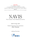
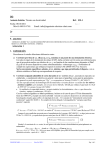
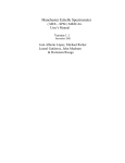
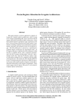
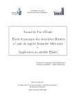
1
EXPERIMENTAL FORM
The Table here below should be filled in so as to follow the changes on your
experiment. For updating this document, use revision bar to show us the modification
in the document.
Changes table:
Index
(*)
0
1
2
3
4
5
6
Campaign
Number
7
7
7
7
7
7
7
Revision
§
date
n° (**)
TBD
All
28-2
3
28-2
4
29-2
4
29-2
5
29-2
9
29-2
12
Short description
of modifications
Not applicable (N/A)
Provided a exactly size of the tank
Clarified a few comments
Added a new picture
Provided more exactly sizes and weight of the rack
Provided a more complete hazard analysis
Update the outreach section
(*) : . the index indicates the issue number of the experimental form.
(**) : the number of modified paragraphs should be indicated.
Team Number :
1017
2
1 – Title of the experiment and Team name
Title of the experiment: Visualization of Richtmyer-Meshkov instability in liquids at zero-g.
Team name : RM-0g
Team Number : 1017
2 – Experiment objectives
The objective of this experiment is to visualize the Richtmyer-Meshkov instability (RMi)
of incompressible fluids in microgravity. The microgravity environment of the parabolic flight
allows a unique opportunity to analyse the complete instability process from the early linear
stages to the final transition to turbulence.
RMi is produced when two separate fluids of different densities are impulsively accelerated in
the direction normal to the interface between the two fluids. It is one of the most fundamental of fluid
instabilities and exhibits many of the non-linear complexities that transform simple initial conditions into
a complex turbulent flow. It is closely related to Rayleigh-Taylor instability, which develops when a
planar interface undergoes constant acceleration, such as caused by the delay of a heavy fluid over a
lighter one in the Earth’s gravitational field.
This instability is important in various fields such as astrophysics [1], high speed
combustions [2] and in inertial confinement fusion (ICF) [3]. In the first case, RMi is believed to
occur in supernovas where the collapsing core of a dying star generates an outward propagating
shock wave, which passes through the helium-hydrogen interface. In the second case, the instability is
observed in supersonic combustion ramjets engines. Finally, in ICF, a high-energy laser beam is used
to compress a spherical shell encapsulating a deuterium-tritium fuel mixture. In this case, RMi appears
in the density interface of the fuel mixture, and the resulting turbulent flux limits the degree of
compression achievable in the process.
RMi experiments have originally been carried out in shock tubes using gases [4], but the major
difficulty in these experiments is in maintaining a well controlled sharp boundary between two gases.
The use of liquids minimizes the problems with generating a sharp well defined interface due to the
low diffusion coefficients of liquids. In addition, the instability in liquids develops at considerably lower
speed, thus greatly simplifying flow visualization. However, the Earth’s gravitational influence becomes
increasingly important as instability growth rates decrease, so such experiments must be carried out in
a low gravity environment. The effects of gravity may be minimized by keeping the fluids in free-fall
while the instability develops [5]. However, the run times achievable with this method are strongly
limited, even using the tallest Drop Towers currently available, and the complete transition into
turbulence has not been yet satisfactorily visualized.
The microgravity environment of the parabolic flight will allow a considerable increment of the
run times achievable on Earth and will give a unique opportunity to take different measurements of
relaxed time in microgravity of RMi and to visualize the complete instability process, from the initial
linear stages, through the non-linear regime and into the final transition to turbulence.
[1] Arnett, W.D., Bachall, J.N., Kirshner, R.P., and Woosley, S.E., “Supernova 1987A,” Annu. Rev. Astron.
Astrophys. (1989), vol. 27, pp. 629-700
[2] Markstein, G.H., “A shock tube study of flame front-pressure wave interaction,” Sixth Symp. (Int) on
Combustion, Reinhold, 387-398 (1957)
[3] Lindl, J.D., McCrory, R.L., and Campbell, E.M., “Progress Toward Ignition and Burn Propagation in Inertial
Confinement Fusion,” Physics Today, 45 (9), 32-50 (1992)
[4] Brouillette, M., and Sturtevant, B. “Experiments on the Richtmyer-Meshkov instability: single scale
perturbations on a continuous interface,” J. Fluid Mech. (1994), vol. 263, pp. 271-292
[5] Niederhaus, C. E., and Jacobs, J. W., “Experimental study of the Richtmyer-Meshkov instability of
incompressible fluids,” J. Fluid Mech. (2003) vol. 485, pp. 243-277
3
3 – Experiment description
The experimental set-up consists of a Lexan tank (35 cm x 20 cm x 5 cm) containing two
immiscible liquids of slightly different densities, mounted to a linear rail system oriented so that the
tank is free to move in the vertical direction, with approximately 1.6 m of net translation length (Fig. 1).
Rails system
Tank with two liquids
Tank oscillating
system
Video camera
Sled
(Fig. 1) Experimental set-up
A moment before the conditions of microgravity, a controlled tiny horizontal oscillation
produced by a simple mechanical system with an electric motor is imparted to the tank to produce a
wavy initial fluid interface shape. The tank is then released from an initial height and allowed to fall
freely along the rail until it reaches the bottom, where a braking system is located to impart the
impulsive acceleration needed to produce the instability. At the moment of the impact, the airplane
must already be in the zero-g parabolic trajectory. Therefore, the instant at which the tank must be
released should be carefully synchronized with the moment at which microgravity is produced. After
the impact, the tank is stationary at the bottom of the rail and the sinusoidal perturbations initially
generated oscillating the tank shall grow, the RMi instability develop and then evolve to the final
turbulent regime. At non-zero gravity conditions the heavier fluid will settle underneath the lighter one,
so the initial conditions are recovered. An accelerometer will continuously record both, the low gravity
conditions during the instability generation and also the initial impulsive acceleration causing the
instability.
A camera coupled to the tank is used for video registration and an appropriate colorant is
dissolved in one of the liquids, allowing a suitable visualization. Despite expected influence of the
surface tension, two immiscible fluids are used to be able to repeat the experiment several times, at
different parabolic trajectories, with distinct initial sinusoidal perturbations at the interface.
Nevertheless, we are also interested in studying the influence of surface tension in RMi.
An analogous experiment has already been built and used to monitor the RMi instability in
liquids on earth at the University of Arizona [5]. The set-up has been here conveniently modified to
overcome the disadvantages and get profit of the advantages provided by the parabolic flights
conditions. The major advantage yields in the fact that the visualization time is going to be much larger
than any previously obtained on earth, which will allow the instability to evolve up to the final
turbulence steps.
4
4 – Technical description of the experiment set-up
The technical set-up for the experiments consist at the moment of 7 elements mounted on a
single rack, which in turn is mounted on the attachment rails. Here is an approximate list of the parts of
the experiment and the materials and equipment that will probably be used to build them:
-
The two rail system: Two aluminium bars of about 1750 mm length will be used.
-
The sled: The sled will be an L-shaped support with appropriate attachments to be coupled to
the rails and another horizontal rail to fix the tank, permitting it’s horizontal oscillation. It will
also include a support for the camera. A strengthened aluminium will probably be used for the
sled base.
-
A tank of net dimensions (35 cm x 20 cm x 5 cm): It will be constructed using Lexan sheets for
the walls, attached together with an appropriate adherent. The thickness of the walls will be
about ~5 mm. However, the bottom wall shall be slightly thicker than the others to strengthen
the tank for the braking shock.
-
The horizontal oscillation system: Will consist of a simple mechanical gear system activated
by an electrical motor. The motor will be directly attached to a small gear, which will in turn be
coupled to a bigger gear with one end of a lever fixed at it’s circumference. The other end of
the lever will be fastened to the tank. With this simple mechanical set-up a constant angular
velocity imparted by the motor can be converted to a perfect sinusoidal oscillation of the tank.
-
Braking system: Different ways of imparting the braking shock are being designed and
studied. A stretching of the aluminium rails at the bottom is one possibility. Another method is
to place an appropriate type of deformable material, such as plastering or a rubber, at the
bottom of the rails to rapidly dissipate the kinetic energy of the sled once it reaches the
bottom. At this moment the team is working in the second option.
-
A video camera: A digital video camera will be used for a reliable registration.
-
An accelerometer: The accelerometer provided by Novespace, in case it’s available, will be
attached to the sled.
The approach for designing the experiment is as follows:
The first point is designing and constructing the experimental apparatus. First, a tank has to be
designed and built. As mentioned, Lexan seems the best choice for the material opposite Plexiglas.
The walls of the tank have to be cut from factory Lexan sheets of an adequate thickness (~5 mm). The
tank has to be perfectly hermetic, double contained and resistant to the impacts that will be imparted
to it. On the other hand, the rails and the sled have to be designed and assembled. The dimensions of
these parts will be approximately the ones mentioned above, but we reserve the possibility of
modifying them slightly in case we find it necessary. Apart from this, the designs of the horizontal
oscillation system and the braking system have to be worked out and then mounted. At last, all the
parts have to be assembled and mechanically tested.
The second point is to decide the exact fluids to be used. Obviously they will be immiscible
and although the surface tension will play an important role in the development of the instability, it will
be interesting to study this role in the RMi.
Finally, the whole system, including the liquids in the tank, will be tested in the lab on-earth to
detect possible malfunctions and to study the achievable braking shock accelerations.
Inside the rack the experiment will be like this:
5
~35 cm
~175 cm
20 cm
5 cm
~60 cm
~60 cm
6
5 – Installation of the experiment in the aircraft
The overall dimensions for this experiment are 1m x 0.65m x 1.75m. It will take up the space
of one rack and the weight should be about 45 kg (rack included). Using Plexiglas, the weight was
about 30 kg, but using Lexan the weight will be a little bit heavier. However, some values can vary
after building the experiment.
Tank with
two liquids
Rack top down view
Tank oscillating
system
100.6 cm
Aircraft rails
Video Camera
~65 cm
6 –Electrical
The power needed supplies just the video camera, and 220V-AC will be needed for this use.
The motor needed to make the small oscillations at the tank will most probably have an internal power
source. If not, the total electrical power needed for the video camera and the motor will be about 30-45
w. The electrical power give here are the expected maximum value.
Confirm that the whole electrical circuits is fitted with one, and only one, emergency
switch-off button (5 cm red pushbutton on yellow box, installed in a such a way to be
easily accessible by the safety team) disconnecting all electrical equipment and
220V-AC and 28 V-DC power supply coming from aircraft electrical panel:
Yes
Confirm that the whole electrical circuit is protected by a fast fuse, adjusted to the
experiment electrical consumption (8 A max for 220V-AC and 20 A max
for 28 V-DC) :
Yes
Fuse value(s) : ………A
Confirm that the whole electrical circuit is protected by ground fault interrupter
adjusted at 30mA :
Yes
7 – Mechanical resistance of the experiment
The experiment will be mounted inside a standard rack attachment boltholes as show in
NOVESPACE´s user manual. There are just one moving part, the tank with the liquids, but it will be
contained inside the rack and it can not cause any injuries.
7
8 – In flight procedures and In flight personnel
The experiment will be conducted as follows: after take-off, the members will check the rack.
During flight (1-g), the members can be at stand-by, but seconds after the first parabola, with the
acceleration of 1.8-g, the two experimenters have to be synchronized to release the sled before the
microgravity environment. Once microgravity conditions are initialised, the experiment will operate on
its own and the instability visualized will be recorded in a video camera. During the parabola it will not
need any manipulation by the team members and when the gravity is restored the experiment shall
return to the initial conditions due to the fluids properties. At last, at 1-g, the team restores the sled
until the initial height waiting for the next parabola. This experiment can be repeated as many times as
parabolic manoeuvres performed by the airplane.
Flight Phase
After take-off
1g
Before first parabola
1.8 g
Seconds before 0g
0g
1.8 g
1g
After the last parabola
Experimenter 1
Checks the rack
Stand-by
Checks the equipment
Prepares to take the measurement
Checks the video camera
Visualization of the RMi
Checks the video tape
Stand-by
Switches the systems off
Experimenter 2
Checks the rack
Stand-by
Checks the fixation holes
Prepares to release the sled
Release the sled
Checks the sled
Release the sled to the initial height
Stand-by
Shuts down the experiment
9 – Hazard analysis
Are there any "dangerous" products (toxic _when swallowed, breathed, eye contact.._
inflammable, infectious, radioactive, corrosive, magnetic, organic…)? No
Are there any pressure systems? No
What could happen in case of a sudden depressurisation (containers destroyed, etc..) ? a
normal decompression (1000 to 700 mbars)? Nothing
Is there any laser? Which class? Is the laser path completely and securely contained ? No
Are there any motors, high electric currents or hot parts near liquid containers ? Yes, but it
can not cause any injury
Confirm that none electrical wire or contact is not shielded and that wire section is convenient
with electrical current uses: Yes
Could there be any electrostatic discharge? No
What happens in case of sudden electrical power loss ? Does the experiment configure itself
in safe idle mode? The experiment shut off.
Are there any electro-magnetic fields generated? No
Any hot part ? What is the maximum external temperature? internal temperature? Are there
temperature limiting devices? Are the lights cold (if any)? Is the light glass contained? The
experiment works at the room temperature
Can you easily access key security items, like push button or pressure vessels tap? Yes
Is it sure that no product, smoke, dust, particles can come from the experiment to the aircraft
cabin (the vent line is made for this)? Yes
Is the experiment very noisy, or produce any smell? No
Is there any moving part ? Is the moving part reachable? Can it create injuries? Yes, but the
moving part is inside the rack and can not cause any injuries
Is there any human subject for the experiment? No
Is the experiment working with a pump filled with oil ? How is the oil leak risk prevented ? No
Is there any device consuming a lot of electrical current when activated/started ? (vacuum
pump, high energy lamp,…) ? How is the start up current limited? No. Unknown
8
Hazard list
1. Liquids escaping the tank
•
Description of hazard
The experiment contains liquids inside a protected tank. The liquids could escape.
•
Hazard causes
Tank fracture during the free fall.
•
Hazard controls
The liquids will not be toxic and the quantity will be minimum to be a hazard. The tank will be made of
Lexan, will be double contained and will be attached with professional glue. It will be mounted and
tested on a Earth-lab for pressure and impact resistance. The sheet will be 5 mm, however all the
equipment will be mounted inside a rack.
10 – Pressure vessel certification (if applicable)
Not applicable yet.
11 – Vent line connection and other requests
Do you need to use the aircraft vent line (throwing experiments wastes out of aircraft)
? : No
9
12 – Outreach Programme
In this section, the following activities before flight are considered:
•
A web page of the RMi project is under construction and is at the following address:
http://www.uib.es/depart/dfs/esa
This page include information about ESA and the parabolic flight campaign (PFC), the
development of the project and will also include pictures or videos of the team and equipment.
•
A summary about the RMi project and the PFC is published at the number of February in the
most important magazine in Spain about astronomy and astrophysics: “Tribuna de
astronomia y Universo”.
• A summary about the RMi project and the PFC is at the university electronic magazine
“ENLLAÇ campus UIB” at the following address:
http://www.campusuib.com/php/seccion.php?nrevista=5&seccion=Estudiants#442
•
A summary about the RMi project and the PFC will be published whether we are short listed
or not at the university magazine “ENLLAÇ UIB”.
• A journalist will cover the development of the project.
• A member of the team, Victor Huarcaya, is writing a diary about the PFC´s experience and
the project. This diary is available in the web page.
• Presentation of the RMi project and the PFC in the science festival at the UIB (aprox. April
2004) and informal lectures in our old respective schools.
The collaboration with the press department of our university, “Servei de Comunicació”, with
Macamen Colom as chief of this department will make a diffusion about the project and the PFC at
the national and local media. This might also include:
•
Press releases in the following newspapers: Diario de Mallorca, El Mundo, Última Hora
and Baleares.
• An interviews in the following TV’s channels: TVE and Antena 3.
• An interviews in the national and local radio.
• A rigorous article in the magazine “Tribuna de astronomía y Universo” about the RMi and
the experience to participate in the ESA´s PFC. We are waiting for the confirmation to write
this article for spring of next year.
We will also give an informal lecture in our university before the campaign in which we will
describe the project and the PFC. We want to motivate other students to attend the PFC and other
ESA´s educational activities like Physics on Stage, SSETI, Space Medicine Workshop, FOTON, YES2
space mail and IAF. However, our primary challenge is encourage the youth students in the schools to
learn and study sciences.
10
13 – Team members and contacts:
Team member 1 :
First Name
Victor
Last Name
Huarcaya
Azañon
Team member 2 :
First Name
Last Name
Nico
Piro
Team member 3 :
First Name
Last Name
Maria
Tous
Team member 4 :
First Name
Last Name
Carles
Bona
University
UIB-Universitat de les
Illes Balears
Phone n°
+34
971206317
Cellular
+34
651905839
Mail
[email protected]
University
UIB-Universitat de les
Illes Balears
Phone n°
+34
971285308
Cellular
+34
667557690
Mail
[email protected]
University
UIB-Universitat de les
Illes Balears
Phone n°
+34
971287941
Cellular
+34
654987224
Mail
[email protected]
University
UIB-Universitat de les
Illes Balears
Phone n°
+34
971615431
Cellular
+34
677690277
Mail
carles.bona@telefonic
a.net
Endorsing Professor
:
Sebastian Monserrat
Experiment location (town and country)
:
UIB. Majorca-Spain.
Name of team member
for ESA contact
:
Victor Huarcaya Azañon
Name of team member
for Novespace contact
:
Victor Huarcaya Azañon
Indicates flight week preferences, if any
: