1
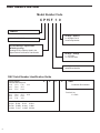
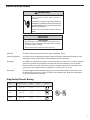
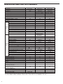
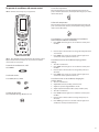
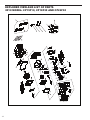
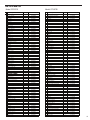
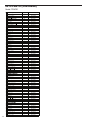
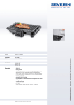
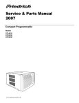
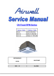
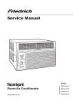
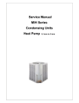
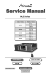
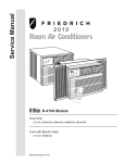
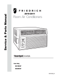
Service & Parts Manual – R410A Models
Compact Programmable
CP-15-18-24-ServParts (05-10)
Model
2010
TECHNICAL SUPPORT
CONTACT INFORMATION
FRIEDRICH AIR CONDITIONING CO.
Post Office Box 1540 · San Antonio, Texas 78295-1540
4200 N. Pan Am Expressway · San Antonio, Texas 78218-5212
(210) 357-4400 · 877-599-5665 x 846 · FAX (210) 357-4490
Email: [email protected]
www.friedrich.com
Printed in the U.S.A.
Table Of Contents
Unit Identification ............................................................................................................................................................. 2
Electrical Data .................................................................................................................................................................. 3
Specifications ................................................................................................................................................................... 4
How to Operate the Air Conditioner with Remote Control ................................................................................................ 5
Method of Charging/Repairs ............................................................................................................................................ 6
Compressor Replacement ................................................................................................................................................7
Troubleshooting .......................................................................................................................................................... 8-10
Wiring Diagrams for 2010 Model .................................................................................................................................... 11
Exploded View of Parts for 2010 Model ......................................................................................................................... 12
Parts for 2010 Models ............................................................................................................................................... 13-14
Warranty ......................................................................................................................................................................... 15
1
Unit Identification
Model Number Code
C P 15 F 1 0
COMPACT
7th Digit – Options
0 = Straight Cool &
Heat Pump Models
PROGRAMMABLE
3rd and 4th Digit - Approximate
BTU/HR (Cooling)
Heating BTU/Hr capacity listed in the
Specification/Performance Data Section
6th Digit – Voltage
1 = 115 Volts
3 = 230-208 Volts
5th Digit
Alphabetical Modifier
RAC Serial Number Identification Guide
Serial Number
Decade Manufactured
L=0
C=3 F=6 J=9
A=1
D=4 G=7
B=2
E=5
H=8
Year Manufactured
A=1
D=4 G=7 B=2
E=5
H=8
C=3 F=6 J=9
K=0
Month Manufactured
A=Jan D=Apr G=Jul
B=Feb E=May H=Aug
C=Mar F=Jun J=Sept
2
K=Oct
L=Nov
M=Dec
A
K
A
K
00001
Production Run Number
Product Line
K = RAC
electrical DATA
WARNING
ELECTRIC SHOCK HAZARD
Turn off electric power before service or
installation.
All electrical connections and wiring MUST be
installed by a qualified electrician and conform to
the National Electrical Code and all local codes
which have jurisdiction.
Failure to do so can result in personal injury or
death.
NOTICE
FIRE HAZARD
Not following the above WARNING could result in fire or
electically unsafe conditions which could cause moderate
or serious property damage.
Read, understand and follow the above warning.
Wire Size
Use ONLY wiring size recommended for single outlet branch circuit.
Fuse/Circuit Breaker
Use ONLY the correct HACR type and size fuse/circuit breaker. Read electrical ratings on unit’s
rating plate. Proper circuit protection is the responsibiity of the homeowner.
Grounding
Unit MUST be grounded from branch circuit through service cord to unit, or through separate
ground wire provided on permanently connected units. Be sure that branch circuit or general purpose outlet is grounded. Ground wire must be connected to ground screw located in lower
right corner of air conditioner when air conditioner is in cabinet. (CP 14, 18, 24)
Receptacle
The field supplied outlet must match plug on service cord and be within reach of service cord.
Do NOT alter the service cord or plug. Do NOT use an extension cord. Refer to the table above
for proper receptacle and fuse type.
Plug/Outlet/Circuit Rating
Model
Circuit Rating
Breaker or T-D Fuse
Plug Face
(NEMA#)
Power Cord
Length (ft.)
CP15
125V - 15A
5 - 15P
6
CP18
250V - 15A
6 - 15P
4
CP24
250V - 20A
6 - 20P
4
Wall Outlet
Appearance
3
Specifications for 2010 models
Model
Product Code
Function
Rated Voltage
Rated Frequency
Total Capacity (W/Btu/h)
Power Input (W)
Rated Input (W)
Rated Current (A)
Air Flow Volume ( CFM ) (H/M/L)**
Dehumidifying Volume ( Pint/h)
EER / C.O.P (W/W)
Energy Class
Fan Type-Piece
Diameter-Length ( inch)
Evaporator
Pipe Diameter ( inch)
(inch)
Indoor Row-Fin Gap
Coil length(l) x height(H)x coil width(L)
Side
Swing Motor Model
Output of Swing Motor (W)
Fuse (A)
Sound Pressure Level dB (A) (H/M/L)
Sound Power Level dB (A) (H/M/L)***
Compressor Manufacturer/trademark
Compressor M odel
Compressor Type
L.R.A. (A)
Compressor RLA(A)
Compressor Power Input(W)
Overload Protector
Throttling Method
Outdoor Starting Method
Side
Working Temp Range ( )
Condenser
Pipe Diameter (inch)
Rows-Fin Gap( inch)
Coil length (l) x height (H) x coil width
Fan Type-Piece
Fan Diameter (inch )
Sound Pressure Level dB (A) (H/M/L)
Sound Power Level dB (A) (H/M/L)
Defrosting Method
Fan Motor Speed (rpm) (H/M/L)
Output of Fan Motor (W)
Fan Motor RLA(A)
Fan Motor Capacitor (uF)
Climate Type
Isolation
Moisture Protection
Permissible Excessive Operating Pressure for
the Discharge Side (P S I )
Permissible Excessive Operating Pressure for
the Suction Side ( P S I )
Dimension (L/W/H)( inch )
Dimension of Package (L/W/H)( inch)
Net Weight /Gross Weight ( LBS )
Refrigerant Charge ( OZ )
4
CP15F10
CC05103400
COOLING
115V
60H z
14700(Btu/h)
1370
1532W
14.9 A
470 /430/410
2.5
3.13
/
Centrifugal flow fan - 1
8.8 X 4.3
Aluminum fin-copper
0.275
2- 1/20
16.6 X1 5 X 1
SM020V
4
/
57/55/54
67/65/64
LANDA
QXA-C129x C030
Rotary
70
11.7
1050
built in
Capillary
64 -110
Aluminum fin-copper
0.275
2-1/20
27.7 X15.75 X 1
Axial fan -1
15.6
61/60/58
71/70/68
/
900/780/730
205
1.78
15
T1
I
IP24
CP18F30
CP24F30
CC05103410
CC05103420
COOLING
COOLING
20 8 /230V
208 /23 0V
60Hz
60Hz
17600/18000 (Btu/h) 23540/24230 (Btu/h)
2500/2580
1640/1680
2052W
3295
10.64A
15A
570 /540 /510
590/560/510
2.8
4.7
3.13
2.75
/
/
Centrifugal flow fan - 1 Centrifugal flow fan - 1
8.8 X 4 . 3
8.8 X 4.3
Aluminum fin-copper Aluminum fin-copper
0.275
0.275
2-1 /20
3- 3/50
16.6 X15 X 1
15.4 X15 X1.5
SM020B
SM020B
4
4
/
/
59/56/54
60/56/54
69/66/64
70/66/64
SHANGHAI HITACHI
LANDA
ELECTRICAL
ASL165RN-C7EG
QXA-F232rK090
Rotary
Rotary
39
52
5.35/5.01
10.5
1120/1150
2375
built in
built in
Capillary
Capillary
64 -110
Aluminum fin-copper
64 -110
Aluminum fin-copper
2-1/20
34 X15.75 X 1
Axial fan -1
15.6
61/60/58
71/70/68
/
1000/900/800
297
1.29
7
T1
I
IP24
2-1/20
34 X15.75 X1
Axial fan -1
15.6
63/61/60
73/71/70
/
1060/970/820
320
1.39
7
T1
I
IP24
0.275
0.275
500
500
500
2 90
2 90
2 90
26 X16.8 X28.5
31.1 X29.1 X20.2
122/151
R410A / 29.98
26 X 16.8 X31.2
36.2 X29.3 X19.7
142/171
R410A / 35.62
26 X 16.8 X31.2
36.2 X 29.3 X19.7
167/184
R410A / 41.98
To operate air conditioner with remote control
NOTE: Remote control may vary in appearance.
To raise the temperature:
Press the plus button to raise the temperature. Each time you
press or hold the plus button, the temperature will go up 1º until it
reaches 86°F (30°C).
To lower the temperature:
Press the minus button to lower the temperature. Each time you
press or hold the minus button, the temperature will go down 1º
until it reaches 64°F (18°C).
To set Timer for a 1- to 24-hour delay before air conditioner
is turned off (air conditioner must be On):
1. Press TIMER. Indicator light on air conditioner control panel
will flash.
NOTE: Two AAA batteries (included) power the remote control.
Replace batteries after 6 months of use, or when the remote
control starts to lose power.
To turn the air conditioner on or off:
Press POWER.
To select the mode:
Press COOL, FAN or $ SAVER
To select the fan speed:
Press FAN SPEED for High, Medium or Low.
2. Press the plus or minus button to change the delay time from
1 to 24 hours.
3. Press TIMER again or wait 10 seconds. Indicator light on air
conditioner control panel will remain on.
To set Timer to turn on air conditioner, keeping previous
settings:
1. Turn off air conditioner.
2. Press TIMER. Indicator light on air conditioner control panel
will flash.
3. Press the plus or minus button to change delay time (1 to
24 hours).
4. Press TIMER again or wait 10 seconds. Indicator light on air
conditioner control panel will remain on.
To set Timer to turn on air conditioner, changing the
previous settings:
1.
2.
3.
4.
5.
6.
Turn on air conditioner.
Adjust Mode to Cool, Fan Only, or Power Saver.
Adjust Fan Speed to High, Medium or Low.
Adjust temperature between 64°F (18ºC) and 86°F (30ºC).
Turn off air conditioner.
Press TIMER. Indicator light on air conditioner control panel
will flash.
7. Press the plus or minus button to change delay time (1 to
24 hours).
8. Press TIMER again or wait 10 seconds. Indicator light on air
conditioner control panel will remain on.
5
Method Of Charging / Repairs
The acceptable method for charging the RAC system is the
Weighed in Charge Method. The weighed in charge method is
applicable to all units. It is the preferred method to use, as it is
the most accurate.
The weighed in method should always be used whenever
a charge is removed from a unit such as for a leak repair,
compressor replacement, or when there is no refrigerant
charge left in the unit. To charge by this method, requires the
following steps:
1. Install a piercing valve to remove refrigerant from the
sealedsystem. (Piercing valve must be removed from the
system before recharging.)
2. Recover Refrigerant in accordance with EPA regulations.
WARNING
BURN HAZARD
Proper safety procedures must be followed,
and proper protective clothing must be worn
when working with a torch.
Failure to follow these procedures could
result in moderate or serious injury.
3. Install a process tube to sealed system.
CAUTION
FREEZE HAZARD
Proper safety procedures must be followed,
and proper protective clothing must be worn
when working with liquid refrigerant.
Failure to follow these procedures could
result in minor to moderate injury.
4. Make necessary repairs to system.
5. Evacuate system to 200 microns or less.
6. Weigh in refrigerant with the property quantity of R-410A
refrigerant.
7. Start unit, and verify performance.
WARNING
BURN HAZARD
Proper safety procedures must be followed,
and proper protective clothing must be worn
when working with a torch.
Failure to follow these procedures could
result in moderate or serious injury.
8. Crimp the process tube and solder the end shut.
6
COMPRESSOR REPLACEMENT
Recommended procedure for compressor
replacement
WARNING
RISK OF ELECTRIC SHOCK
Unplug and/or disconnect all electrical power
to the unit before performing inspections,
maintenances or service.
Failure to do so could result in electric shock,
serious injury or death.
1.
Be certain to perform all necessary electrical and
refrigeration tests to be sure the compressor is
actually defective before replacing.
WARNING
3.
After all refrigerant has been recovered, disconnect
suction and discharge lines from the compressor and
remove compressor. Be certain to have both suction
and discharge process tubes open to atmosphere.
4.
Carefully pour a small amount of oil from the suction
stub of the defective compressor into a clean
container.
5.
Using an acid test kit (one shot or conventional kit), test
the oil for acid content according to the instructions
with the kit.
6.
If any evidence of a burnout is found, no matter how
slight, the system will need to be cleaned up following
proper procedures.
7.
Install the replacement compressor.
WARNING
HIGH PRESSURE HAZARD
Sealed Refrigeration System contains refrigerant
and oil under high pressure.
EXPLOSION HAZARD
The use of nitrogen requires a pressure
regulator. Follow all safety procedures and
wear protective safety clothing etc.
Proper safety procedures must be followed,
and proper protective clothing must be worn
when working with refrigerants.
Failure to follow proper safety procedures
result in serious injury or death.
Failure to follow these procedures could
result in serious injury or death.
2.
Recover all refrigerant from the system though
the process tubes. PROPER HANDLING OF
RECOVERED REFRIGERANT ACCORDING TO
EPA REGULATIONS IS REQUIRED. Do not use
gauge manifold for this purpose if there has been
a burnout. You will contaminate your manifold and
hoses. Use a Schrader valve adapter and copper
tubing for burnout failures.
8. Pressurize with nitrogen and leak test all connections with
an electronic or Halide leak detector. Recover refrigerant
and repair any leaks found.
Repeat Step 8 to insure no more leaks are present.
9.
WARNING
HIGH TEMPERATURES
Extreme care, proper judgment and all safety
procedures must be followed when testing,
troubleshooting, handling or working around
unit while in operation with high temperature
components. Wear protective safety aids
such as: gloves, clothing etc.
CAUTION
FREEZE HAZARD
Proper safety procedures must be followed,
and proper protective clothing must be worn
when working with liquid refrigerant.
Failure to do so could result in serious burn
injury.
Failure to follow these procedures could
result in minor to moderate injury.
NOTICE
FIRE HAZARD
The use of a torch requires extreme care and proper
judgment. Follow all safety recommended precautions
and protect surrounding areas with fire proof materials.
Have a fire extinguisher readily available. Failure to follow
this notice could result in moderate to serious property
damage.
Evacuate the system with a good vacuum pump capable
of a final vacuum of 300 microns or less. The system
should be evacuated through both liquid line and suction
line gauge ports. While the unit is being evacuated, seal
all openings on the defective compressor. Compressor
manufacturers will void warranties on units received not
properly sealed. Do not distort the manufacturers tube
connections.
10.
Recharge the system with the correct amount of
refrigerant. The proper refrigerant charge will be
found on the unit rating plate. The use of an accurate
measuring device, such as a charging cylinder,
electronic scales or similar device is necessary.
7
COOLING ONLY ROOM AIR CONDITIONERS: TROUBLESHOOTING TIPS
Problem
Possible Cause
Fuse blown or circuit tripped
Replace fuse, reset breaker. If repeats, check
fuse or breaker size. Check for shorts in unit
wiring & components
Power cord not plugged in
Plug it in
Unit does not run System switch in “OFF” position
Inoperative system switch or open
control board
Loose or disconnected wiring at
switch, control board or other components
Problem
Evaporator coil
freezes up
Problem
Check wiring & connections. Reconnect per
wiring diagram
Action
Clean as recommended in Owner ’s Manual
Restricted airflow
Check for dirty or obstructed coil. Use
pressure wash or biodegradable cleaning
agent to clean
Inoperative t-stat or thermistors
Test for continuity
Short of refrigerant
De-ice coil & check for leak
Inoperative fan motor
Test fan motor & replace if inoperative
Partially restricted capillary tube
De-ice coil. Check temp. differential (delta T)
across coil. Touch test coil return bends for
same temp. Test for low running current
Possible Cause
Thermistor shorted
8
Test for continuity
Dirty filter
Compressor runs Restriction in line
continually & does
not cycle off
Refrigerant leak
Control does not
turn unit off
Set switch correctly
Possible Cause
Excessive heat load
Problem
Action
Possible Cause
Action
Unit undersized. Test cooling performance &
replace with larger unit if needed
Check for partially iced coil & check
temperature split across coil
Check for oil at silver soldered connections.
Check for partially iced coil. Check split across
coil. Check for low running amperage
Replace thermistor or electronic control board
Action
Control at coldest point
Turn to higher temp. setting to see if unit
cycles off
Incorrect wiring
Refer to appropriate wiring diagrams
Unit undersized for area to be
cooled
Refer to industry standard sizing chart
Defective thermistor
Replace thermistor or electronic control board
COOLING ONLY ROOM AIR CONDITIONERS: TROUBLESHOOTING TIPS
Problem
Possible Cause
Overload inoperative. Opens too
soon
Check operation of unit. Replace overload if
system operation is satisfactory
Compressor restarted before
system pressures equalized
Allow a minimum of 2 minutes to allow
pressures to equalize before attempting to
restart. Instruct customer of waiting period
Compressor runs
Low or uctuating voltage
for short periods
only. Cycles on
overload
Incorrect wiring
Problem
T-stat does not
turn unit on
Problem
Noisy operation
Problem
Water leaks into
the room
Action
Check voltage with unit operating. Check for
other appliances on circuit. Air conditioner
should be in separate circuit for proper voltage
& fused separately
Refer to appropriate wiring diagram
Shorted or incorrect capacitor
Check by substituting a known good capacitor
of correct rating
Restricted or low air ow through
condenser coil or evaporator coil
Check for proper fan speed or blocked
coils
Compressor running abnormally
hot
Check for kinked discharge line or restricted
condenser. Check amperage
Possible Cause
Action
Loss of charge in t-stat bulb
Place jumper across t-stat terminals to check if
unit operates. If unit operates, replace t-stat.
Loose or broken parts in t-stat
Check as above
Incorrect wiring
Refer to appropriate wiring diagram
Defective thermistor
Replace thermistor or electronic control board
Possible Cause
Action
Poorly installed
Refer to Installation Manual for proper
installation
Fan blade striking chassis
Reposition - adjust motor mount
Compressor vibrating
Check that compressor grommets have not
deteriorated. Check that compressor mounting
parts are not missing
Improperly mounted or loose
cabinet parts
Check assembly & parts for looseness,
rubbing & rattling
Possible Cause
Action
Evaporator drain pan over owing
Clean obstructed drain trough
Condensation forming on base pan
Evaporator drain pan broken or cracked.
Reseal or replace. No chassis gasket installed.
Install chassis gasket
Poor installation resulting in rain
entering the room
Check installation instructions. Reseal as
required
Condensation on discharge grille
louvers
Dirty evaporator coil. Use pressure wash
or biodegradable cleaning agent to clean.
Environmental phenomena: point supply
louvers upward
Chassis gasket not installed
Install gasket, per Installation manual
Downward slope of unit is too
steep inward
Refer to installation manual for proper
installation
9
COOLING ONLY ROOM AIR CONDITIONERS: TROUBLESHOOTING TIPS
Problem
Water “spitting”
into room
Problem
Excessive
moisture
Problem
Thermistor
short cycles
Problem
Prolonged off
cycles (automatic
operation)
Possible Cause
Ensure that foam gaskets are installed in
between window panes & in between the
unit & the sleeve. Also, ensure that fresh
air/exhaust vents (on applicable models) are in
the closed position & are in tact
Downward pitch of installation is
too steep towards back of unit
Follow installation instructions to ensure that
downward pitch of installed unit is no less than
1/4” & no more than 3/8”
Restricted coil or dirty filter
Clean & advise customer of periodic cleaning
& maintenance needs of entire unit
Possible Cause
Outside water
leaks
10
Action
Insufficient air circulation thru area
to be air conditioned
Adjust louvers for best possible air circulation
Oversized unit
Operate in “MoneySaver” position
Inadequate vapor barrier in building
structure, particularly floors
Advise customer
Possible Cause
Action
Defective thermistor
Replace thermistor or electronic control board
Plenum gasket not sealing,
allowing discharge air to short
cycle unit
Check gasket. Reposition or replace as
needed
Restricted coil or dirty filter
Clean & advise customer of periodic cleaning
& maintenance needs of entire unit
Possible Cause
Action
Disconnect plus from outlet. Remove resistor
from bracket. Insert plug & depress “COOL”
Heat anticipator (resistor) shorted or
& “FAN AUTOMATIC” buttons. Place t-stat to
open
warmest setting. Feel resistor for temperature.
If no heat, replace resistor
Defective thermistor
Problem
Action
Sublimation:
When unconditioned saturated,
outside air mixes with conditioned
air, condensation forms on the
cooler surfaces
Possible Cause
Replace thermistor or electronic control board
Action
Evaporator drain pan cracked or
obstructed
Repair, clean or replace as required
Water in compressor area
Detach shroud from pan & coil. Clean &
remove old sealer. Reseal, reinstall & check
Obstructed condenser coil
Use pressure wash or biodegradable cleaning
agent to clean
Fan blade/slinger ring improperly
positioned
Adjust fan blade to 1/2” of condenser coil fin
pack
ELECTRONIC CONTROL
WIRING DIAGRAM: 2010 MODEL
CP15F10 / CP18F30 / CP24F30
11
EXPLODED VIEW AND LIST OF PARTS
2010 MODEL: CP15F10, CP18F30 AND CP24F30
12
2010 PARTS
Model CP15F10
No
Description
Model CP18F30
Qty
Friedrich Part#
1 S u p p o r te r A s s y
1
2 S c r e w S T 4. 2X 13
7
67700200
67700154
67700113
67700151
67700128
67700129
67700201
67700202
67700203
67700204
67700155
67700149
67700170
67700205
67700158
67700153
67700206
67700152
67700285
67700157
67700159
67700117
67700286
67700110
67700112
67700209
67700109
67700127
67700130
67700210
67700124
67700211
67700121
67700125
67700212
67700116
67700108
67700106
67700103
67700213
67700288
67700296
67700156
67700217
67700131
67700218
67700270
67700220
67700221
67700114
67700259
67700136
67700223
67700160
67700224
67700225
67700226
67700227
67700259
67700229
67700230
67700231
67700232
67700233
67700234
67700235
67700236
67700296
67700105
67700171
3 W i n d o w l o c k i n g b ra c k et
2
4 Screw 4X20
6
5 Seal strip 1
1
6 Seal strip 2
1
7 Curtain Assemby Left and Right
1
8 R i g h t C u r ta i n
1
9 L e f t C u r ta i n
1
10 Cabinet Assy
1
11 S c r e w S T 4. 2X 6. 5
6
12 Screw M4X8
1
13 Connect cord
1
14 Screw M4X5
1
15 Washer 4
1
16 S c r e w S T 4. 2X 22
4
17 T o p R a i l A s s y
1
18 S c r e w S T 4X 10
4
19 C o n d e n s e r A s s y
1
2 0 N u t w i th W a s h e r M 1 0
1
21 Washer 10
1
22 Fan Blade
1
23 S h r o u d , F a n B l a d e
1
24 Top Cover
1
2 5 M o to r S u p p o r t
1
2 6 M o to r C J 1 0 0 U
1
27 Innerwall
1
28 Shroud
1
2 9 A i r O u tl e t F o a m
1
30 S w i n g L o u v e r
2
31 S w i n g L i n k a g e
2
3 2 M o to r , S w i n g L o u v e r
1
3 3 I n f l e c ti o n a l A x i s
1
34 S w i n g S u p p o r t
1
35 F r e s h A i r D o o r
1
36 B l o w e r W h e e l
1
37 O r i f i c e ( c l a p b o a r d )
1
3 8 B a s e P l a te o f A i r F l u e
1
3 9 E v a p o r a to r A s s y
1
40 S e n s o r H o l d e r
1
4 3 C o m p r e s s o r G r o m m e ts
3
4 4 N u t w i th w a s h e r M 8
3
45 C a p i l l a r y A s s y
1
46 Water Tray
1
47 C a p a c i to r 15u F /300V A C
1
48 C a p a c i to r 50u F /450V
1
50 Transformer 41X26.5C
1
51 C a p a c i to r c l a m p
1
52 Electronic Control Kit
1
53 Electric box
1
5 4 I s o l a ti o n W a s h e r D
1
55 Wire Clamp
1
56 Power cord
1
57 R e c e i v e r C o v e r
1
58 Membrane
1
5 9 C o n tr o l P a n e l C o v e r A
1
60 Electronic Control Kit
1
61 F r o n t P a n e l A s s y
1
62 G u i d e L o u v e r L i n k a g e
1
63 Filter
1
64 G u i d e L o u v e r
14
65 Front Case
1
66 Front Panel
1
67 A S W i n d o w P a n e l
1
6 8 R e m o te C o v e r P a n e l
1
69 B a s e p a n ( c h a s s i s )
1
70 C h a s s i s F i x e r
1
71 Remote Control
1
No
Description
Qty
1 Supporter Assy
1
2 Self-threading Screw ST4.2x22
7
3 Window Locking Bracket
2
4 Screw 4X20
6
5 Seal Strip 1
1
6 Seal Strip 2
1
7 Curtain Assemby Left and Right
1
8 Right Curtain
1
9 Left Curtain
1
10 Cabinet Assy
1
11 Self-threading Screw ST4.2X6.5
6
12 Screw Assay M4x8
1
13 Connect Cord
1
14 Screw M4X6
1
15 Washer 4
1
16 Self-threading Screw ST4.2x22
6
17 Top Rail
1
18 Self-threading Screw with Gasket ST4X10
4
19 Condenser Assy
1
20 Nut with Washer M10
1
21 Washer 6
1
22 Fan Blade
1
23 Shroud, Fan Blade
1
24 Top Cover (Upper Clapboard)
1
25 Motor Support
1
26 Motor CJ100B
1
27 Innerwall
1
28 Blower Front
1
29 Air Outlet Foam 1
1
30 Swing Louver
2
31 Lever of Vertical Guider
2
32 Swing Motor SM020B
1
33 Inflectional Axis
1
34 Cross Beam
1
35 Fresh Air Door
1
36 Blower Wheel
1
37 Orifice (clapboard)
1
38 Base Plate of Air Flue
1
39 Evaporator Assy
1
40 Insert Block
2
41 Compressor 2K25S236AHF
1
43 Compressor Grommets
3
44 Nut with Washer M8
3
45 Capillary Assay
1
46 Water Tray
1
47 Capacitor 7uF/450V
1
48 Capacitor CBB65 40uF/450V(TUV)
1
49 Relay 841-S-1A-D 200V/240V TUV
1
50 Power Transformer 41X26.5F
1
51 C a p a c i to r C l a m p
1
52 Electronic Control Kit
1
53 Electric box
1
54 Isolation Washer D
1
55 Fixed Clamp
1
56 Power cord
1
57 Receiver Cover
1
58 Membrane
1
59 Control Panel Cover
1
60 Electronic Control Kit
1
61 Front Panel Assy
1
62 Guide louver linkage
1
63 Filter
1
64 Guide louver
8
65 Up Filter Guide
1
66 Front Panel (Down Filter Guide)
1
67 AS Window Panel
1
69 Basepan
1
70 Chassis Fixer
1
71 Remote Control
1
Friedrich Part#
67700132
67700154
67700113
67700151
67700128
67700129
67700166
67700168
67700167
67700271
67700155
67700149
67700170
67700150
67700158
67700153
67700134
67700152
67700239
67700157
67700159
67700117
67700273
67700110
67700112
67700241
67700109
67700127
67700130
67700120
67700124
67700133
67700121
67700125
67700123
67700274
67700108
67700106
67700287
67700141
67700289
67700292
67700156
67700294
67700131
67700145
67700279
67700147
67700146
67700114
67700260
67700136
67700223
67700160
67700169
67700138
67700148
67700137
67700260
67700229
67700122
67700231
67700118
67700140
67700139
67700135
67700297
67700105
67700171
13
2010 PARTS (Continued)
Model CP24F30
No
14
Qty
Friedrich Part#
1 S u p p o r te r A s s y
Description
1
2 S c r e w S T 4. 2X 13
7
4 S c r e w 4X 20
6
5 S e a l s tr i p 1
1
6 S e a l s tr i p 2
1
67700200
67700154
67700113
67700151
67700128
67700129
67700201
67700202
67700203
67700238
67700155
67700149
67700170
67700205
67700158
67700153
67700206
67700152
67700239
67700157
67700159
67700117
67700208
67700240
67700112
67700265
67700109
67700242
67700130
67700210
67700124
67700133
67700121
67700125
67700212
67700243
67700108
67700106
67700266
67700213
67700290
67700293
67700156
67700295
67700131
67700145
67700299
67700147
67700247
67700172
67700261
67700136
67700223
67700160
67700249
67700225
67700226
67700227
67700261
67700229
67700230
67700231
67700232
67700233
67700234
67700235
67700236
67700298
67700105
67700171
8 R i g h t C u r ta i n
1
9 L e f t C u r ta i n
1
10 C a b i n e t A s s y
1
11 S c r e w S T 4. 2X 6. 5
6
12 S c r e w M 4X 8
1
13 C o n n e c t c o r d
1
14 S c r e w M 4X 5
1
15 Washer 4
1
16 S c r e w S T 4. 2X 22
4
17 T o p R a i l A s s y
1
18 S c r e w S T 4X 10
4
19 C o n d e n s e r A s s y
1
2 0 N u t w i th W a s h e r M 1 0
1
21 W a s h e r 10
1
22 F a n B l a d e
1
23 S h r o u d , F a n B l a d e
1
24 T o p C o v e r
1
2 5 M o to r S u p p o r t
1
2 6 M o to r C J 1 0 0 U
1
27 I n n e r w a l l
1
28 Shroud
1
2 9 A i r O u tl e t F o a m
1
30 S w i n g L o u v e r
2
31 S w i n g L i n k a g e
2
3 2 M o to r , S w i n g L o u v e r
1
3 3 I n f l e c ti o n a l A x i s
1
34 S w i n g S u p p o r t
1
35 F r e s h A i r D o o r
1
36 B l o w e r W h e e l
1
37 O r i f i c e ( c l a p b o a r d )
1
3 9 E v a p o r a to r A s s y
1
40 S e n s o r H o l d e r
1
4 4 N u t w i th w a s h e r M 8
3
45 C a p i l l a r y A s s y
1
4 6 W a te r T r a y
1
48 C a p a c i to r 50u F /450V
1
49
1
Relay 841-S-1A-D 110/120V
50 Transformer 41X26.5C
1
51 C a p a c i to r c l a m p
1
5 3 E l e c tr i c b o x
1
5 4 I s o l a ti o n W a s h e r D
1
55 W i r e C l a m p
1
56 P o w e r c o r d
1
57 R e c e i v e r C o v e r
1
58 M e m b r a n e
1
61 F r o n t P a n e l A s s y
1
63 Filter
1
64 G u i d e L o u v e r
14
65 F r o n t C a s e
1
66 F r o n t P a n e l
1
67 A S W i n d o w
1
6 8 R e m o te C o v e r P a n e l
1
69 B a s e p a n ( c h a s s i s )
1
70 C h a s s i s F i x e r
1
7 1 R e m o te C o n tr o l
1
Friedrich Air Conditioning Company
P.O. Box 1540
San Antonio, TX 78295
210.357.4400
www.friedrich.com
ROOM AIR CONDITIONERS
LIMITED WARRANTY
FIRST YEAR
ANY PART: If any part supplied by FRIEDRICH fails because of a defect in workmanship or material within twelve months from
date of original purchase, FRIEDRICH will repair the product at no charge, provided room air conditioner is reasonably accessible
for service. Any additional labor cost for removing inaccessible units and/or charges for mileage related to travel by a Service
Agency that exceeds 25 miles one way will be the responsibility of the owner. This remedy is expressly agreed to be the exclusive
remedy within twelve months from the date of the original purchase.
SECOND THROUGH FIFTH YEAR
SEALED REFRIGERANT SYSTEM: If the Sealed Refrigeration System (defined for this purpose as the compressor, condenser
coil, evaporator coil, reversing valve, check valve, capillary, filter drier, and all interconnecting tubing) supplied by FRIEDRICH in
your Room Air Conditioner fails because of a defect in workmanship or material within sixty months from date of purchase,
FRIEDRICH will pay a labor allowance and parts necessary to repair the Sealed Refrigeration System; PROVIDED FRIEDRICH will
not pay the cost of diagnosis of the problem, removal, freight charges, and transportation of the air conditioner to and from the
Service Agency, and the reinstallation charges associated with repair of the Sealed Refrigeration System. All such cost will be the
sole responsibility of the owner. This remedy is expressly agreed to be the exclusive remedy within sixty months from the date of the
original purchase.
APPLICABILITY AND LIMITATIONS: This warranty is applicable only to units retained within the Fifty States of the U.S.A., District
of Columbia, and Canada. This warranty is not applicable to:
1.
2.
3.
Air filters or fuses.
Products on which the model and serial numbers have been removed.
Products which have defects or damage which results from improper installation, wiring, electrical current
characteristics, or maintenance; or caused by accident, misuse or abuse, fire, flood, alterations and/or misapplication
of the product and/or units installed in a corrosive atmosphere, default or delay in performance caused by war,
government restrictions or restraints, strikes, material shortages beyond the control of FRIEDRICH, or acts of God.
OBTAINING WARRANTY PERFORMANCE: Service will be provided by the FRIEDRICH Authorized Dealer or Service
Organization in your area. They are listed in the Yellow Pages. If assistance is required in obtaining warranty performance, write
to: Room Air Conditioner Service Manager, Friedrich Air Conditioning Co., P.O. Box 1540, San Antonio, TX 78295-1540.
LIMITATIONS:
THIS WARRANTY IS GIVEN IN LIEU OF ALL OTHER WARRANTIES. Anything in the warranty
notwithstanding, ANY IMPLIED WARRANTIES OF FITNESS FOR PARTICULAR PURPOSE AND/OR MERCHANTABILITY
SHALL BE LIMITED TO THE DURATION OF THIS EXPRESS WARRANTY. MANUFACTURER EXPRESSLY DISCLAIMS AND
EXCLUDES ANY LIABILITY FOR CONSEQUENTIAL OR INCIDENTAL DAMAGE FOR BREACH OF ANY EXPRESSED OR
IMPLIED WARRANTY.
Performance of Friedrich’s Warranty obligation is limited to one of the following methods:
1. Repair of the unit
2. A refund to the customer for the prorated value of the unit based upon the remaining warranty period of the unit.
3. Providing a replacement unit of equal value
The method of fulfillment of the warranty obligation is at the sole discretion of Friedrich Air Conditioning.
NOTE: Some states do not allow limitations on how long an implied warranty lasts, or do not allow the limitation or exclusion of
consequential or incidental damages, so the foregoing exclusions and limitations may not apply to you.
OTHER: This warranty gives you specific legal rights, and you may also have other rights which vary from state to state.
PROOF OF PURCHASE: Owner must provide proof of purchase in order to receive any warranty related services.
All service calls for explaining the operation of this product will be the sole responsibility of the consumer.
All warranty service must be provided by an Authorized FRIEDRICH Service Agency, unless authorized by FRIEDRICH prior to
repairs being made.
(10-08)
15