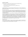
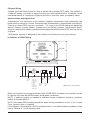
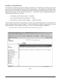
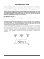
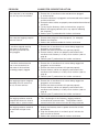
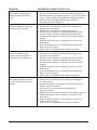
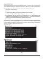
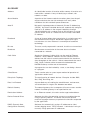
1
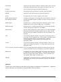
MODEL NDP1 NAFEM GATEWAY MODEL NDP1 701 S. RIDGE AVENUE TROY, OHIO 45374-0001 937-332-3000 www.hobartcorp.com FORM 35374 (Sept. 2005) TABLE OF CONTENTS GENERAL . . . . . . . . . . . . . . . . . . . . . . . . . . . . . . . . . . . . . . . . . . . . . . . . . . . . . . . . . . . . 3 Product Overview . . . . . . . . . . . . . . . . . . . . . . . . . . . . . . . . . . . . . . . . . . . . . . . . . . . 4 Network Services . . . . . . . . . . . . . . . . . . . . . . . . . . . . . . . . . . . . . . . . . . . . . . . . 4 INSTALLATION . . . . . . . . . . . . . . . . . . . . . . . . . . . . . . . . . . . . . . . . . . . . . . . . . . . . . . . 5 Physical Locations . . . . . . . . . . . . . . . . . . . . . . . . . . . . . . . . . . . . . . . . . . . . . . . . . . 5 Optimum Physical Location Configuration . . . . . . . . . . . . . . . . . . . . . . . . . . . . . . . 5 Ethernet Gateway Architecture — Possible Configurations . . . . . . . . . . . . . . 6 Ethernet Wiring . . . . . . . . . . . . . . . . . . . . . . . . . . . . . . . . . . . . . . . . . . . . . . . . . . Authentication and Registration . . . . . . . . . . . . . . . . . . . . . . . . . . . . . . . . . . . . . . . Installation & RS485 Wiring . . . . . . . . . . . . . . . . . . . . . . . . . . . . . . . . . . . . . . . . . . . RS485 and MODBus Settings . . . . . . . . . . . . . . . . . . . . . . . . . . . . . . . . . . . . . . . . . Gateway Configuration . . . . . . . . . . . . . . . . . . . . . . . . . . . . . . . . . . . . . . . . . . . . . . 7 7 7 8 9 TROUBLESHOOTING . . . . . . . . . . . . . . . . . . . . . . . . . . . . . . . . . . . . . . . . . . . . . . . . . 10 LED Descriptions . . . . . . . . . . . . . . . . . . . . . . . . . . . . . . . . . . . . . . . . . . . . . . . . . . 10 Problem / Suggested Corrective Action . . . . . . . . . . . . . . . . . . . . . . . . . . . . . . . . 11 Ping Instructions . . . . . . . . . . . . . . . . . . . . . . . . . . . . . . . . . . . . . . . . . . . . . . . . . . . 13 Glossary . . . . . . . . . . . . . . . . . . . . . . . . . . . . . . . . . . . . . . . . . . . . . . . . . . . . . . . . . 14 Service . . . . . . . . . . . . . . . . . . . . . . . . . . . . . . . . . . . . . . . . . . . . . . . . . . . . . . . . . . 16 Model NDP1 © HOBART, 2005 –2– Installation, Operation and Care of MODEL NDP1 NAFEM GATEWAY SAVE THESE INSTRUCTIONS GENERAL This manual is intended for the user who is already familiar with the NAFEM protocol and Ethernet connections. For more information see: NAFEM DATA PROTOCOL USER MANUAL located at: http://www.nafem.org/resources/tech/DataProtocol.cfm The NDP1 is a gateway device that, when used with compatible Hobart equipment, can make the system NAFEM Data Protocol compliant. The NDP1 performs protocol conversion from MODBus over RS485 to TCP/IP over Ethernet. You do not have to be a computer expert to understand what the gateway can do for you and how it is going to be applied. The first thing you need to know is that a protocol is simply a set of rules that instructs or tells the computer how it can communicate. It is like a language and the rules of grammar that we use to talk with each other. Computers talk to each other over wires or through radio waves using protocols. NAFEM has worked with its members to develop a 'common' protocol for use in foodservice equipment. Using this protocol, information about the equipment can be shared with a computer system. Information that may be shared could include HACCP data, asset information about the equipment, maintenance information and so forth. Networking is very common in most office environments. The NAFEM Protocol uses networking concepts that are very typical. If you use the Internet on your computer at home, you are networking with computers all over the world. You may also use computers in your workplace to share POS or inventory data. When your network administrator connects the gateway to the network and adds an application software package on the computer, you will be able to hook up from one to eight pieces of Hobart and Traulsen equipment that are NDP (NAFEM Data Protocol) compatible. These pieces of equipment will send data to a specified computer on site or at a central location. The data collected will be managed by an application software system installed on the target computer. The kitchen equipment will run normally and have only a slight difference in the installation. When adding the Gateway to your facility, a network connection will start at either the target computer or the router to the Ethernet going to the Gateway. From this point an RS485 cable (like a telephone cable) will extend from the Gateway to the first piece of equipment. If more than one piece of equipment is to be connected, a "daisy chain" configuration will connect one unit to the other. A diagram of this configuration is shown on page 6. The remainder of this manual gives further details to installing the NAFEM Data Protocol system in your facility. Your network administrator will be able to complete the installation hookup and software set-up. –3– PRODUCT OVERVIEW The model NDP1 has three physical connectivity points to the physical world: • The device’s EIA-485 serial communication port, • The RJ45 Ethernet network communication port (10BaseT), and • The power supply jack. The NAFEM Gateway is a protocol converter that connects Hobart / Traulsen equipment to the NAFEM protocol using an Ethernet connection. The requirements are set forth by NDP using digital signal connectivity. This Gateway device performs these tasks and achieves NAFEM Data Protocol compliance with the use of six firmware components: Poll Engine, Alarm Module, SNMP v1 Agent, Web Server, TFTP Client, and a Device Protocol Driver. In addition, a database resides within the gateway that contains the NAFEM Objects. This is where the information is exchanged between the NAFEM and MODBus elements. The function of the gateway is to receive requests for reads and writes of NAFEM Objects. These objects are the registers within the target equipment. This request comes to the gateway in the format of the NAFEM protocol. The gateway converts the request into the appropriate format and communicates with the target equipment. If connected in a daisy chain configuration (page 6), up to 8 pieces of equipment can be connected to one gateway. The gateway can access up to 80 registers (i.e. 80 different pieces of data) divided between these targets. The information returned to the gateway from the target equipment is converted into the NAFEM protocol and sent to the SNMP Manager, the Web browser or the application software. Network Services The NDP1 supports DHCP client, staticIP, and autoIP for address assignment. Normally you will not need to make any changes. Intelligence is employed within the gateway to revert to backup IP assignment methods if the primary method is unavailable. –4– INSTALLATION PHYSICAL LOCATIONS There must be no more than 160 feet of RS485 cable within a configuration having one Gateway. This means that one Gateway with up to 8 machines must have a total of no more than 160 feet of RS485 cable. A configuration with two Gateways and up to 16 machines total must have no more than160 feet of RS485 cable in each Gateway cluster for a total of no more than 320 feet of RS485 cable for the two-Gateway configuration. A power adapter cord with six feet of lead is provided; 120 volts, 60 hertz, 1 phase grounded outlet is required. Power adapter cord must be plugged in prior to installation. The Gateway and power cord must be located away from areas that will be sprayed with water or any other liquids, and any devices that can emit electrical dsiturbances, such as microwave ovens, radios or other Gateways. The Power Supply must be installed such that condensate cannot drip down the cord into the 120 volt outlet. The Gateway and power cord must be located in an area where the ambient temperature is less than 100°F and where there is minimal risk of condensate. It is recommended that the Gateway be mounted above the equipment on the upper portion of a wall or above a dropped ceiling. Installation must be in accordance with all applicable local or national electrical codes. OPTIMUM PHYSICAL LOCATION CONFIGURATION If multiple machines will be networked through the same Gateway, a daisy chain connection must be utilized. Refer to Installation on page 6 for details. One connection cable is provided. If more than one machine is to be connected, additional cables can be purchased from Hobart (order kit number 893512). Hobart suggests that the machines for any one Gateway be clustered within 15 feet of the Gateway regardless of the length of cable between the machines and the Gateway. If the machines are more than 15 feet away from the Gateway, a second Gateway should be used. NOTE: NAFEM Data Protocol Gateway can be implemented in an Ethernet wireless configuration such as the 802.11b wireless protocol. Components to install in this manner are supplied by others. Connections between the target equipment and the Gateway must be hard wired with an RS485 connection cable. –5– NAFEM Gateway Architecture — Possible Configurations –6– Ethernet Wiring Connect an RJ-45 Ethernet jack to a Hub or Switch with standard CAT5 cable. The gateway is a 10BaseT device, so a switch is the best solution for a multi-speed network. The device can be connected directly to a computer’s Ethernet jack with a crossover cable, provided by others. Authentication and Registration Authentication and registration of the Gateway happens automatically once connections are made and may take up to 1 minute. Communication to the network is accomplished via the DHCP Client to a system DHCP service, if available. The result of the DHCP method will define the device’s Internet Protocol address, SubNet mask and Default gateway. The Microsoft AutoIP scheme is employed to address possible networking environments where DHCP services are not available. The Ethernet interface is designed to work without user intervention on most networks. Installation & RS485 Wiring 0.19 dia. 3.3 5.0 5.5 Pin 12345 ••••• •••• 1.3 0.12 6789 Device Activity LED Pin 1 Not Used 2 Not Used 3 Not Used 4 T+/R+ 5 Com 6 T-/R7 Not Used 8 Not Used 9 Not Used Ethernet RJ45 Ethernet Activity LED 5 VDC Power Pos Center Ethernet Link LED Dimensions are in inches. Refer to Installation Instructions on Nafem Cable , FORM 35375, included, for instructions on how to connect and route the NAFEM cables inside Hobart machines. NOTE: If additional cables are needed for additional length or additional machines, purchase Hobart Kit Number 893512. NOTE: Use proper ESD handling procedures when making connections to unit. A UL Listed Class 2 power supply is supplied. If the Gateway is connected to a DHCP-enabled network, it can be browsed at the address listed next to "Browse at" on the Gateway label. –7– Installation and RS485 Wiring (continued) Connect one end of one RJ-12 Machine cable (Hobart part no. 893493-1 or 893493-2) to the Gateway Adapter (Hobart part no. 893494). Connect the Gateway Adapter to the Gateway. Connect the other end of the Machine Cable to one of the ports on the double port side of the Y-Adapter Connector (Hobart part no. 893902). Connect one end of the second RJ-12 Machine Cable (Hobart part no. 893493-1 or 893493-2) to the single port side of theY-Adapter Connector. Connect the other end of the second Machine Cable to the machine. Refer to NAFEM Gateway Architecture — Possible Configurations on page 6 for instructions on how to connect and route the NAFEM cables between the Gateway and the machines. RS485 and MODBus Settings All Hobart machines have their bit rate set at 9600 bits per second. Refer to each machine's Operators manual or Service Department for specific instructions on how to verify the bit rate setting. All machines must have unique MODBus IDs. Refer to each machine's Operators Manual or Service Department for specific instructions on how to verify the MODBus ID. –8– GATEWAY CONFIGURATION The Gateway may be configured via a web-based interface. To access this interface, open a web browser on a PC connected to the same LAN as the Gateway. In the address bar of the browser, type in either the IP address or the address printed on the Gateway label and press Enter. The configuration options are on the left panel (Fig. 1). All options can be configured individually. Three important options to note are: • IP Address under Administration → Network • Time and Date under Clock/Calendar → Clock • Data Points to access under Gateway → Serial Port Entry The first option set with the submit button will open a password dialogue box. The default user name is new and the password is user. For more information on how to change the user name and password or other configuation options, refer to the Watlow Manual located at: http://www.watlow.com/literature/prodtechinfo/files/controllers/nafem_b.pdf Fig. 1 –9– TROUBLESHOOTING When the Poll Engine attempts to read from a remote device and an error occurs, the Poll Engine will immediately retry to read from the remote device. If all retries have failed, then the Poll Engine will increment the protocol read message failure count by one and attempt the next poll attribute. If all active attributes for a single device fail, then the poll engine will disengage the device from the poll cycle. When the Poll Engine attempts to write to a remote device and an error occurs, the Poll Engine will immediately retry to write to the remote device. If all retries have failed, then the Poll Engine will increment the protocol write message failure count by one and reset the programmable attribute for the write operation to the previous write value. LED DESCRIPTIONS (Fig. 2) The Ethernet Link LED is on continuously when there is an active Ethernet link between the Gateway and the rest of the network. If the LED is off at any time, check all power and network cables for proper connection. The Ethernet Activity LED flashes intermittently as Ethernet traffic flows across the network to and from the Gateway. Any time the Gateway sends or receives data, the LED will flash and then turn off. If the LED remains off for an extended period, ensure that the Ethernet Link LED is on and that all power and network cables are properly connected. The Device Activity LED flashes intermittently as serial data flows between the Gateway and the machines connected to it via the RS485 port. Any time the Gateway sends or receives data the LED will flash briefly and then turn off. The configuration of the Gateway will determine the interval between flashes. Typically, this interval is between 30 seconds and 5 minutes. If there is no activity and the LED remains off for an extended period, ensure that the Gateway is properly enabled, all cables are properly connected and all machines connected to the Gateway are powered on. Fig. 2 – 10 – PROBLEM SUGGESTED CORRECTIVE ACTION The computer is not recording data for any of the machines. 1. Ensure that all machines to be monitored are plugged in and turned on. 2. Ensure the Gateway is plugged in and connected to the network and the machines. 3. Ensure the data cables are properly connected to the monitored machines. 4. Try to ping the Gateway (refer to instructions, page 13). 5. Restart the logging software (this may require rebooting the computer). 6. Contact your IT professional for further assistance. The computer logging program does not launch. 1. Ensure other programs launch properly (i.e. notepad). 2. Reboot the computer. 3. Contact the software vendor for further assistance. A machine stopped working and none of the properly functioning machines are being logged. 1. Ensure that all machines that are not being logged are plugged in and turned on. 2. Ensure that those machines still operate properly. 3. Ensure the data cables are properly connected to the machines and Gateway in a daisy-chain fashion (refer to page 6). 4. Contact your IT professional for further assistance. A machine received service from a service technician and none of the machines are being properly logged. 1. Ensure that all machines that are not being logged are plugged in and turned on. 2. Ensure that those machines still operate properly. 3. Ensure the data cables are properly connected to the machines and Gateway in a daisy-chain fashion (refer to page 6). 4. Contact your IT professional for further assistance. The logging program stopped recording data for some, but not all, of the machines. 1. Ensure that all machines that are not being logged are plugged in and turned on. 2. Ensure that those machines still operate properly. 3. Ensure the data cables are properly connected to the machines and Gateway in a daisy-chain fashion (refer to page 6). 4. Contact your IT professional for further assistance. The logging software records unexpected values for several minutes after a system restart. 1. This is by design of the Gateway, logging software, and method of communication. The problem should correct itself within several minutes of being restarted. The logging software needs to be restarted multiple times a day. 1. Unplug the Gateway from its power source for at least 60 seconds. 2. Plug the Gateway back in and wait up to 5 minutes for data transfer to resume. 3. Contact the software vendor for further assistance. – 11 – PROBLEM SUGGESTED CORRECTIVE ACTION The Gateway itself needs its power cycled multiple times a day. 1. Ensure that the Gateway is away from other devices that could be sending out interfering signals, such as microwave ovens, radios, networking equipment and other Gateways. 2. Contact your local Hobart Service team to replace the potentially faulty Gateway. Values recorded for one of the machines never changes. 1. Ensure that all machines providing false readings are plugged in and turned on. 2. Ensure that all machines are operating properly. 3. Ensure correct readings are displayed on the machines. 4. Ensure the data cables are properly connected to the machines and Gateway in a daisy-chain fashion (refer to page 6). 5. Unplug the Gateway from its power source for at least 60 seconds. 6. Plug the Gateway back in and wait up to 5 minutes for data transfer to resume. 7. Contact your IT professional for further assistance. Values recorded for one machine are much higher or lower than what is expected. 1. Ensure that all machines providing false readings are plugged in and turned on. 3. Ensure correct readings are displayed on the machines. 4. Ensure the data cables are properly connected to the machines and Gateway in a daisy-chain fashion (refer to page 6). 5. Unplug the Gateway from its power source for at least 60 seconds. 6. Plug the Gateway back in and wait up to 5 minutes for data transfer to resume. 7. Contact your IT professional for further assistance. The computer program launches, but nothing else seems to happen. 1. Ensure that all machines to be monitored are plugged in and turned on. 2. Ensure the Gateway is plugged in and connected to the network and the machines. 3. Ensure that the machines being monitored are operating normally. 4. Attempt to ping the Gateway (refer to instructions, page 13). 5. Unplug the Gateway from its power source for at least 60 seconds. 6. Plug the Gateway back in and wait up to 5 minutes for data transfer to resume. 7. Contact your IT professional for further assistance. – 12 – PING INSTRUCTIONS Ping can be performed on most computer operating systems. To perform a 'ping' command from a 32-bit Windows machine (i.e. Windows 95, 98, Me, NT, 2000 or XP), follow instructions below. For operating systems other than Windows, contact your network administrator. 1) Click Start on the menu bar 2) Click Run 3) In the dialog that appears, type the word command and then click OK 4) A Command Prompt (or MS-DOS box) will appear 5) At the command line, type ping #.#.#.#, where the #.#.#.# is the IP address of the Gateway that is having problems (as in the first line of Fig. 3). [You may have to get this number from your network administrator, manager or Help Desk.] 6) Press Enter If the command is successful, meaning there is not a network communications problem between the Gateway and your PC, then you will receive text similar to that of the second box in Fig. 3. If the command is unsuccessful, meaning there is a network communication or configuration error, you will receive text similar to that of Fig. 4. Successful ping Fig. 3 Unsuccessful ping Fig. 4 – 13 – GLOSSARY Address An identifiable location. A location within memory. A location of a node within a network. A way of identifying a network, sub network, or node. Alarm Module A portion of the firmware code that monitors data from the poll engine and alerts the user (for example via E-mail) about conditions that fall outside of preset tolerances. Auto IP Microsoft's implementation of Automatic Private IP Addressing (APIPA). An Auto IP-enabled device will automatically configure itself to an IP address in the range of 169.254.0. through 169.254.255.254 with a subnet mask of 255.255.0.0 if it cannot reach a DHCP server or if it does not have a fixed, hard-coded IP address. Baseband A type of channel where data transmission is carried across only one communication channel. Baseband supports one signal transmission at a time. Ethernet is an example of baseband technology. Bit rate The rate, usually expressed in seconds, that bits are transmitted. Broadcast Simultaneous transmission of the same data to all nodes connected to a network. Cat5 Cable Stands for Category 5 cable which can be used for Ethernet networks. Many 10BaseT networks use this standard, which defines how the cable is manufactured and what the maximum data throughput on the cable is. Hobart recommends the use of Cat5, Cat5e, or better cable to communicate between the NAFEM Gateway and the rest of the network. Client A program that can be invoked by a user; a user being a human or a program. Client/Server Terms used to refer to a peer to peer method of operation of applications within hosts. Daisychain Topology The configuration of network devices. Examples include: BUS, Star, Ring, Dual Ring, etc. Data Link Protocol A prescribed way of handling the establishment, maintenance, and termination of a logical link between two nodes. Default Gateway The network gateway that a computer will use to access another network if another gateway is not specified for use. Destination Address In an Ethernet network, this refers to the target node address. Device Protocol Driver Software that links the operating system to a peripheral device using a specific protocol. The driver contains the precise machine language necessary to perform the functions requested by the application. DHCP (Dynamic Host Configuration Protocol) Software that automatically assigns IP addresses to client stations logging onto a TCP/IP network. It eliminates having to manually assign permanent IP addresses – 14 – Domain Name System A service used with TCP/IP to replace the previous method of keeping track with host names, aliases, and internet addresses. The domain name service is a distributed database used to convert node names to internet addresses. ESD Electrostatic discharge. Ethernet A data link level protocol. It comprises layers one and two when compared to the OSI reference model. Ethernet is a broadcast technology and can be implemented with different media types, such as thick or thin coaxial cable or twisted pair cable. Ethernet uses CSMA/CD mechanism to access the medium. Ethernet Address A 48 bit address, commonly referred to as a hard address. This address identifies an Ethernet network interface card (NIC), thus identifying a host hardware address. Firmware Computer programs contained permanently in a hardware device (as a read-only memory) Interface A shared point between two entities, either software or hardware. Internet Address A 32-bit address used to identify hosts and networks. Internet Protocol (IP) The part of the TCP/IP protocol that handles routing of data. Link Used to refer to a connection between two end points. Local Area Network (LAN) A collection of computer related equipment connected in such a way that communication can occur between all nodes connected to the medium. Management Information Base (MIB) A database containing configuration and statistical information about nodes on a network. MODBus A high level protocol for industrial networks, it defines a request / response message structure for a client / server environment. NAFEM North American Association of Food Equipment Manufacturers NAFEM Gateway A protocol converter that converts Hobart / Traulsen equipment to the NAFEM protocol using an Ethernet connection. NDP1 A Gateway device that, when used with compatible Hobart Equipment, can make the system NAFEM Data Protocol compliant. Network A collection of computers and related devices connected so that communication can occur. Network Address In TCP/IP networks, this refers to the IP Address of a node. Network Administrator The person designated to maintain the network. This person should have working knowledge of network wiring, requirements, etc. See System Administrator. Ping A program used with TCP/IP networks. The Ping program provides a way of testing access to a destination by sending an ICMP echo request, then waiting for a response from the target host. – 15 – Poll Engine A portion of the firmware code that requests (polls) data from the connected target equipment and stores that data for later use. Protocol A set of rules governing the method of operation. Protocol Conversion Changing one type of protocol to another type of protocol. RS-485 A physical layer specification for connecting devices. Server An application that answers requests from clients. SNMP (Simple Network Management Protocol) A widely used network monitoring and control protocol. Data are passed from SNMP agents to SNMP managers used to oversee the network. SNMP Agents Hardware and / or software processes reporting activity in each network device (hub, router, bridge, etc.) using SNMP. SNMP Manager Hardware and / or software processes on a workstation console used to oversee the network that use SNMP. Subnet Mask A mask used to determine to what subnet an IP address belongs. Subnetting enables the network administrator to further divide the host part of the address into two or more "sub-networks" (or subnets). TCP Transmission Control Protocol. A transport layer protocol that is part of the TCP/IP protocol suite. TCP provides a reliable stream mechanism performing re-transmission when a positive acknowledgment is not returned to the source from the destination node. TCP/IP Transmission Control Protocol / Internet Protocol. TCP/IP is an upper layer networking protocol. It is client/server based at the application layer. TFTP (Trivial File Transfer Protocol) A TCP/IP based application used for transferring files from one system to another that has no directory or password capability. Web Server A computer that delivers Web pages to browsers and other files to applications via the HTTP protocol. It includes the hardware, operating system, Web server software, TCP/IP protocols and site content (Web pages and other files). 10BaseT A reference to the cabling used in an Ethernet network. Meaning 10Megabits per second, using baseband signaling, and twisted pair cabling. SERVICE Contact your local Hobart service office for any repairs needed on this equipment. Long-term service contracts are available on this and other Hobart products. FORM 35374 (Sept. 2005) – 16 – PRINTED IN U. S. A.