1
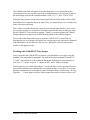
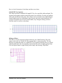
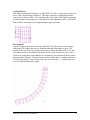
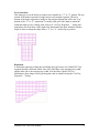
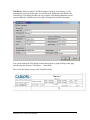
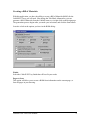
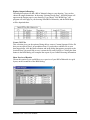
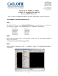
8319 State Route 4
Mascoutah, IL 62258 USA
Phone : 800-658-4641
Fax : 618-566-3250
www.cablofil.com
Cablofil Visio Tools User Manual
Installation:
1) Make sure that a copy of Visio 5.0c, or Visio 2000 is currently installed on your
computer.
2) From the Cablofil CD or website at www.cablofil.com, double-click on the setup
file named Cablofil.EXE. This will start the installation process.
3) Follow the setup wizard’s instructions to install this program.
Once the installation is complete, you should have an item in the Start> Programs menu
called Cablofil Visio Tools 1.0. Within that menu item, two sub-menu items should
appear.
The first, named Cablofil Visio Tools, will open the Cablofil template and stencils in
Visio. The second sub-menu item is an Uninstall program, which will remove all of the
Cablofil specific files from your computer, if you choose to do so.
After installation, you will also have a shortcut icon on your desktop. Double clicking
this icon will perform the same action as the first Program menu item, which will launch
Visio and open the Cablofil template and stencils.
The installation will also add the Cablofil templates to the Visio File> New list, and two
Toolbar buttons to the Visio interface. These will give you access to the Cablofil EZ Tray
shapes from within Visio.
Getting Started:
You should understand some basic operations in Visio. To proceed you need to know
how to drag a master of the stencil and drop it on the drawing page, how to zoom in and
out on a drawing page and move from page to page within a document. The Visio help
utility and user manual can give you some information to get started. Once you know
these basics, this tutorial will direct you through any other Visio operations that are
necessary to work with the Cablofil application.
Accessing the Cablofil Shapes:
Cablofil Visio Tools User Manual
1
You can access the Cablofil shapes and page setup several different ways.
1) If you want to create a new Visio drawing from the Cablofil template (which has
a default scale of 1/8”=1’), you can access it in two places:
a. From the Start> Programs menu, choose Cablofil Visio Tools.
b. From within Visio, choose the File> New> Cablofil > Cablofil to open the
template and accompanying stencils.
2) If you have an existing drawing that you would like to add Cablofil EZ Tray
shapes to, simply click one of the Cablofil Toolbar buttons.
The first button enables you to convert or add the Cablofil designer.
If you choose to convert your existing drawing, the Cablofil designer will insert the
Cablofil EZ Tray stencils, and add the Cablofil menu item. This conversion process gives
your drawing the functionality of the Cablofil application by adding the code necessary
for this automated solution to work. If the converter detects an existing automated
solution already present in the drawing, you will have the option to merge the solutions
together, or to have the existing solution replaced with the Cablofil solution.
Cablofil Visio Tools User Manual
2
The Cablofil menu item will appear next to the Help menu. As an option during this
conversion process, you can also convert the existing drawing’s size and scale, to that of
the default page setup for the Cablofil template (Scale: 1/8”= 1’, Size: 352ft x 272ft).
Doing this may produce unexpected existing shape behavior based on the scale in which
these shapes were originally drawn. In light of this, you should always save existing work
before converting a drawing.
There will be a reminder during the conversion process that when the file is to be saved
(or resaved), to make sure to check the Workspace option in the Save As dialog in order
for the Cablofil EZ Tray stencils to reappear. Finally, your other option in the Cablofil
Designer dialog is to open a new Cablofil drawing based on the Cablofil template.
The second toolbar button allows you to open the Cablofil EZ Tray stencils in any
drawing that you are working with. In this case, the drawing is not converted or enhanced
with automation code, but the same file Save As> Workspace rule from the previous
section would apply here also.
Working with Cablofil EZ Tray shapes:
Once you opened the Cablofil EZ Tray stencils, you add shapes to your page using the
standard Visio drag and drop paradigm. The stencils have been arranged by depth (1.5”,
2” and 4”) and contain all of the widths for that depth. Each depth is represented by its
own color: 1.5” shapes are green, 2” shapes are blue, and 4” shapes are purple.
The last stencil is one called “Multishapes”, which will allow a more experienced user to
access all the different size combinations for a particular shape in one place. You set the
different combinations for each shape by right clicking the shape, and choosing “Set Tray
Properties…” Certain shapes will have other custom menu items to choose from as well.
Cablofil Visio Tools User Manual
3
Here is a brief description of each shape and how to use them:
Cablofil EZ Tray Segment:
This shape represents a standard 10ft length EZ Tray for a specified width and depth. The
segments snap together with the connection point on one end (blue X) to the gray padlock
on the other end (locked end point). These shapes can be stretched to any length using the
control handle (green box with shaded center on same end as the connection points). If
you pause the pointer tool over the control handle, a tip will appear letting you know
what the control is used for on the shape.
90 Degree Elbow:
This elbow is used to represent 90 Degree bends in your Cablofil drawing. They also
connect to the end of a Cablofil EZ Tray segment shape’s connection points. The only
difference in gluing this shape to a Cablofil EZ Tray segment is that they have two locked
endpoints that snap to the corresponding connection points on the straight segment shape.
You can flip this shape by right clicking on the shape, and choosing “Flip Elbow”.
Cablofil Visio Tools User Manual
4
Variable Elbow:
This shape represents the forming of a Cablofil EZ Tray elbow, whose angle can be set to
above, below and including 90 Degrees. This shape connects to straight segments the
same as the 90 Degree Elbow. You can change the offset angle of this shape by dragging
its control handle to the angle you would like the second segment to bend to. Like the 90
Degree Elbow, this shape can be flipped using its right click menu.
Flex Segment:
The Flex Segment represents a 10ft long Cablofil EZ Tray that needs to form a larger
radius bend. This shape also has two control handles that help change its form. The
control on the end of the Flex Segment allows you to adjust the angle of the curve end.
The control nearer to the middle of the shape can be moved to adjust the curve corner
location. By using these control handles in combination, you can make the flex segment
bend around any obstacle. The other feature to note for this shape is setting its Inscribe or
Circumscribe property. This is found in the “Set Tray Properties…” menu that you can
access by right clicking on the shape.
Cablofil Visio Tools User Manual
5
Tee Connection:
This shape gives you the ability to connect trays together in a “T” or “Y” pattern. The top
portion of the shape represents a bridge between two straight segments. The lower
portion of the shape represents a bridge for the straight segment that will be the “Leg”
portion of the “T” or “Y” connection. To modify each part of the shape to match the
width and depth you are working with, refer to its “Set Tray Properties…” dialog and
manipulate sizes from there. Other right click functionality has been included with this
shape in order to change the shape from a “T” to a “Y”, and to flip its position.
Reduction:
A Reduction represents a shape that will bridge the gap between two Cablofil EZ Tray
segments that have different widths. One side of the shape is the incoming tray width,
and the other side is the outgoing tray width. Like the other Cablofil EZ Tray
Multishapes, these shapes can be glued together and are modified using the “Set Tray
Properties…” dialog.
Cablofil Visio Tools User Manual
6
Title Block: When you add a Title Block shape to a page in your drawing, it will
automatically resize to fit that page. It is laid out in an ANSI style, and includes the
Cablofil logo. The dialog box that you use to edit the Title Block information can be
accessed from the Cablofil menu, or by right clicking on the initial Design page.
You can also delete the Title Block from the design page by right clicking on the page,
and choosing the “Remove Title Block…” menu item.
Here is how the bottom corner of the Title Block looks.
Cablofil Visio Tools User Manual
7
Creating a Bill of Materials:
With this application, you have the ability to create a Bill of Materials (BOM) for the
Cablofil EZ Trays you will need. Like editing the Title Block information, you can
generate a Bill of Materials from the Cablofil menu, or via right click on the design page.
The generation process begins after you make your selections, and click the Start button.
Lets take a look at the options you have in the BOM dialog:
Finish:
Select the Cablofil EZ Tray finish that will best fit your needs.
Pages to Scan:
This option will allow you to create a BOM from information on the current page, or
from all pages in your drawing.
Cablofil Visio Tools User Manual
8
Display Output in Drawing:
Choosing this option will add a Bill of Materials shape to your drawing. You can also
choose the output destination. In choosing “Existing Design Page”, the BOM shape will
appear on the Design page in your drawing. If you choose “New BOM Page”, the
program will add a page to your drawing called Bill of Materials, and the BOM shape
will be deposited there.
Create CSV File:
This selection gives you the option of being able to create a Comma Separated Value file
that you can open in Excel, in spreadsheet form. If you decide to add this file to your
drawing package, click the Browse button, and in the dialog that appears, navigate to the
location where you would like to save it, name the file, and click Save. Clicking the Start
button in the BOM dialog will complete the export of your Cablofil drawing information.
Show Preview of Results:
Choose this option if you would like to see a preview of your Bill of Materials in a grid
layout, on the second tab of the BOM dialog.
Cablofil Visio Tools User Manual
9
Exit When Processing is Completed:
Choosing this option will close the BOM dialog box after processing of the Cablofil
information in your drawing has completed. This option cannot be selected if you have
chosen to see a preview of the results, or vise versa.
Printing a Drawing:
Print by using the standard Visio Print command in the File menu. If you are using a
color printer, the trays will print in colors corresponding to the tray depth as displayed on
the Visio screen. These colors print as shades of gray on a black and white printer, so
you may want to change the printer option in the Print dialog box by checking “Color as
black”. This will produce black lines on a white background.
Cablofil Visio Tools User Manual
10