1
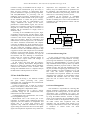
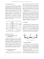
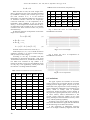
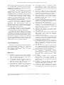
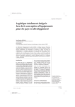
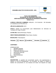
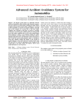
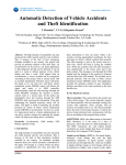
Sensors & Transducers, Vol. 178, Issue 9, September 2014, pp. 34-39
Sensors & Transducers
© 2014 by IFSA Publishing, S. L.
http://www.sensorsportal.com
Research and Application of Digital Transmission
of Unbonded Elastic Wire Resistance Type Sensor
Guilin Zheng, Zhenjie Wang
School of Power and Mechanical Engineering, Wuhan University, Wuhan 430072, China
E-mail: [email protected], [email protected]
Received: 22 June 2014 /Accepted: 29 August 2014 /Published: 30 September 2014
Abstract: By analyzing different resistance values, this collector of this article collects signal of the Unbonded
Elastic Wire Resistance Type Sensor (UEWRTS in brief) acquisition embedded in the dams, reservoirs and
other hydraulic buildings, and monitors the facilities in real time view. The position of embedded sensors can be
distinguished by setting the address and code. The analog signal is one-on-one converted to digital signals
through high-precision analog-to-digital conversion and amplification chips by digitized transducers. The digital
signals are transported to the central server, and the deformation of the structure is estimated by original data in
the server. Meanwhile, it extended the transformer’s effective measuring distance from normal analog
200 meters up to digitalized 1200 meters. In situation of multi UEWRTS installed field, all the output of the
transformers can be connected in parallel to eliminate the cables to only one RS485-Bus as a twisted-pair cable
and a power line. Applications of the transducer in several reservoir dams’ security monitoring system proof that
is of high accuracy, reliable, strong anti-interference solution for all the UEWRTS applications of the relative
monitoring and measurement projects. The collector has been applied in dam monitoring, and achieved good
results. Copyright © 2014 IFSA Publishing, S. L.
Keywords: Unbonded Elastic Wire Resistance Type Sensor, Wire resistance, Five-wire Transformer, Wire
resistance, Concrete crack, Concrete temperature.
1. Introduction
According to the function, Unbonded Elastic
Wire Resistance Type Sensor, which is used to make
long-term observation to internal structural
parameters of the buildings in all kinds of
construction fields, can be divided into the stress,
strain and infiltration pressure, temperature, crack
and so on for observation to different physical
quantities [1-2]. Through the information collection
of resistance sensor, the effective analysis for
hydraulic structure deformations and internal
temperature changes of bridges or dams can be got.
With the 24-bit high-precision Analog to Digital
Converter, a group of resistances from the sensor can
34
be made accurate measurement [3-4]. According to
these resistances, which are taken into the formula of
hydraulic
structure
detection,
the
internal
deformations of several of building fields can be
monitored. Such has made important significance to
the lives of dwellers neighboring.
Previously, through resistance sensor, the
resistance can be got with the indirect method that
the line resistance is measured and its value is
computed [5]. Such method presents the
shortcomings such as complex computation,
occupying a considerable amount of resources,
bringing great load to MCU. Currently the output
structure of UEWRTS is five-wire system, which is
taken five lines of different colors as the cable
http://www.sensorsportal.com/HTML/DIGEST/P_2349.htm
Sensors & Transducers, Vol. 178, Issue 9, September 2014, pp. 34-39
resistance testing of UEWRTS and the output of
mutual resistance measurement [6-7]. This essay is
taken five-wire resistance as background, highprecision ADS1232 as signal processing component,
and NECμPD78F0881 as processing unit for
intelligent signal processing, parameterization and
bus. Meanwhile it takes DC-DC as the power supply
for the transducer to ensure full power isolation,
which can resist 2500 Vpp back-flashover over
voltage. Additional the output of the sensor,
photoelectric isolated RS485 signal, also has the
similar level of isolation voltage. The transducer is
designed in a metal rod body with 4 centimeters in
diameter and 20 centimeters in length, which is
facilitate to bury.
According to the embedded micro-power, highperformance microprocessor and the relative signal
conditioning circuit, the transducer can measure each
resistance's value and its change within sensors and
cable lines accurately. With the coordination and
administration of the microprocessor, the transducer
can achieve automatic measurement and complete
correction. In addition [8], all the parameters can be
set remotely by RS485 communication. The adoptive
AD chip within the transducer achieves a high
resolution of 24-bit. The embedded temperature chip
is applied to monitor and compare the environmental
parameters of the measured structure. With the AD
conversion technology, the transducer can wipe off
the influence and error affecting on measurement
results which are caused by different lengths of
resistive sensors' output cables and changes in
environmental temperature.
In this context, this paper takes the collector,
installed in spillway dam Wuhan Daoguan-River
Reservoir in China, for example, and the transducer
collection and calculation of the resistance value
through the embedded sensors to complete analysis
the deformation and temperature of the dam.
2. Part of the Hardware
As shown in the Fig. 1, the hardware includes
five parts: central processing unit, power
management unit, communication unit, measurement
unit and five-wire UEWRTS.
Central processing unit is made up of Micro
Control Unit (MUC), which is the control center.
Degree of intelligence is depended on MCU.
Power management unit is used to support
controllable energy for the communication unit,
measurement unit and UEWRTS.
Communication unit communicates with central
sever through RS485 signals.
Measurement unit is the central part of the
transducer. It includes signal conditioning and AD
acquisition unit and collection of temperature and
storage unit. As a 24-bit high precision AD
acquisition chip, ADS1232 transforms the analog
signal coming from resistance devices into the digital
signal. The temperature acquisition chip collects the
temperature and compensates for results. The
memory chip sets address and basic parameters for
the transducer. The transmission unit transmits the
collected information and processing results to the
remote server. The working current is 25 mA.
UEWRTS of the hardware is embedded
previously in different acquisition positions, when
the dam is building. Five wires of the UEWRTS are
extended from the underground to connect with the
measurement unit.
Fig. 1. Block diagram of collector.
2.1. Central Processing Unit
As the central processing unit, microcomputer
chip NECμPD78F0881 is responsible for receiving,
processing and distribution of peripheral signals of
devices [9]. NECμPD78F0881 is a kind of single
chip researched and developed by NEC Corp and its
outstanding industrial properties make it stable and
reliable in usage .This chip has abundant resources:
44 pins, the built-in single-supply flash memory, the
built-in watchdog; six timers including two 16- and
four 8-bit; the internal integrated 8-channel
10-resolution AD acquisition module; the internal
integrated CAN controller. In the hardware, MCU
commands and schedules other unit work, which
plays the role of control center by exchanging
information.
2.2. Power Management
The transducer is responsible for collecting dam
internal parameters periodically, and the practical
application of the working time is far less than the
non-working time. Considering low power, the
power part of achieves function of controllable power
by using the PMOS transistor switches to supply
power on the acquisition part and UEWRTS. Power
is on under control in the acquisition time. Power is
off under control after acquisition time, and
transducer gets into standby mode waiting to be
recalled by communication or the timer. This design
is conducive to extend sensor life while
saving energy.
35
Sensors & Transducers, Vol. 178, Issue 9, September 2014, pp. 34-39
2.3. Communication Unit
As shown in Fig. 2, ADM2483 is of enhanced
isolation RS485 transceiver device, which includes a
three-channel isolator, a drive controller of tri-state
output, and a receiver of three-state input. The chip
has thermal shutdown protection function, whose
isolation voltage can reach 2500 V, and instant high
common mold suppression ability can reach
25 kV/μs. These features allow the sensor to have
reliable overvoltage, over current protection, and
anti-jamming capability. In the application and
installation system of a multi-sensor bus form, it
plays an important role in protection of the entire
communication bus. In addition, max emission
current of the chip is only 2.5 mA. Low-power
design not only conserves energy, but also reduces
the chip fever, thus failures are avoided because of
high fever an airtight system.
and so many important parameters. According to
different number of address, not only can many
sensors and transducers work through parallel bus,
but also multiple transducers communicate and
acquire measured value based on a bus cable, and no
address conflicts or packet loss can be ensured.
Memory chip of 24C02 has 1K memory space, which
can provide ample space for the relevant parameters
of transducer to store.
Calibration of the test data by the temperature can
be completed by synchronous detection of ambient
temperature of the sensor and transducer. The
transducer integrated by high-precision temperature
monitoring unit, exports resistance values, while
putting out temperature of environment at the same
time. Practice has proved that, the integrated
temperature sensor DS18B20 has high detection
speed, high accuracy, and good stability [11-12], so
that the transducer can not only fully meet the
demand of temperature correction, but also as
intelligent transducer put out multi-parameter.
2.5. UEWRTS
Fig. 2. Schematic of internal serial communication.
Unbonded elastic wire resistance device is
usually buried in the deeper location of the dam or a
variety of architectural structures previously. Value
of resistances of cables is too much to be ignored,
because cables of sensors are generally long. AS
shown in Fig. 3, R1 and R2 are resistances to be
measured, r1, r2, r3, r4 and r5 are all resistances of the
cable lines. It is because of five-wire configuration,
resistances of the cables can be measured and errors
are available to be avoided in the final results [13].
2.4. Measurement Unit
2.4.1. Signal Conditioning and AD
Acquisition Unit
Because UEWRTS is five-ware structure,
ADS1232 is chose as acquisition chip. ADS1232 is
of dual-channel high-precision 24-bit ADC [10].
Integrated programmable gain amplifier (PGA) is
internal of chip ADS1232, which includes a thirdorder modulator, a fourth-order digital filter and an
internal oscillator. Its internal structure is able to
provide a complete front-end solution for the
resistance measurement sensor. The resistance of a
sensor changes from 40 Ω to 120 Ω. According to the
range measurement of the resistance of the sensor,
the full scale measurement range is set as 120 Ω.
2.4.2. Collection of Temperature
and Storage Unit
Memory chips are used to store various types of
transducer parameters for setting the address, range
36
Fig. 3. Five-wire Resistance.
3. The Programming
As shown in Fig. 4, the program flowchart of the
transducer and different sensors are distinguished by
setting different addresses. The number of address of
sensors can be set from 01 to 32 by digital interface
of RS485-Bus. It should be noted that addresses of
sensors must be assigned one-to-one before
connecting with the bus, and a same address of
different sensors is not allowed.
After the address is assigned, the RS485 cables of
the transducers connect with the central server as a
bus, and master-slave mode is used in
communication between multiple sensors and central
Sensors & Transducers, Vol. 178, Issue 9, September 2014, pp. 34-39
server and multiple sensors [14]. Transducer
responds to the central server according to the
address of an instruction. When the address of the
command does not match, the sensor takes no action.
The first type is the core of the instruction: after
receiving the order, the transducer begins to collect
temperature and resistance value then transfer the
value back to the collection center.
When acquisition instruction is got from central
service, measurement unit and UEWRTS are
powered on. Values of temperature and resistances
are collected, and data is packed and sent to the
server. After receiving confirm instruction from the
server, measurement unit and UEWRTS are powered
off waiting for the next acquisition instruction. If
confirm instruction is not received from the server in
a certain period of time, data is sent in the second
time. If confirm instruction is still not got,
measurement unit and UEWRTS are powered off.
The transducer, controlled by remote center of
Personal Computer, gets collection cycle by
configuration according to the need of the project.
Transducers have four times for collecting daily:
6:00, 12:00, 18:00 and 24:00 [6], which can meet the
needs of structural telemetry observations. When
necessary, cycle detection can be configured fastest
detection to one minute.
4. Stricture of Transducer
Unbonded elastic wire resistance device is
usually buried within the structure been observed, so
transducer, supporting the design, must be of small
size, rugged construction and can be buried. In this
article, the digital transducer is divided into two parts
of signal conditioning and microprocessor circuit
design, and the upper and lower parts are fixed by
pins, which is easy to fix within the tubular shell. The
thickness of shell is 5 mm of metallic materials. As
shown in Fig. 5 and Fig. 6 show, the transducer can
be directly buried near the resistance for its solid
structure, so it can complete digital transmission of
analog sensors in the nearest place; advanced
isolation technology of power supply and digital
output communication interface of the transducer has
been taken; electrical standards of capacity of
counter-attack voltage 2500 Vpp in RS485 and
power supply against lightning can be achieved [15];
grade IP68 of the waterproof from overall structure
of the transducer can be reached; capacity of bearing
400 kg/cm2 geotechnical engineering requirements
can be achieved.
Fig. 5. Side view of internal structure.
Fig. 6. Top view of internal structure.
5. Practical Application and Analysis
Taking one used in a large reservoir spillway as
an example, the transducer of the research, the
spillway has 18 resistive sensors buried in the
construction process. The buried sensors are divided
into two categories: first class for the deformation
detection; second class of observations for the
temperature. After the transducers are digitalized
respectively, corresponding addresses are: address 01
to 15 for the first category; address 16 to 18 for the
second category.
Set resistances as R1 and R2 of a resistance sensor.
The usual method of detection is to calculate ratio Z
of two resistances:
Z = 10000 × R1 / R2 ,
Fig. 4. The program flowchart.
and detection of resistance and R is:
37
Sensors & Transducers, Vol. 178, Issue 9, September 2014, pp. 34-39
Table 2. Result of measurement (Temperature oC).
R = R1 + R2
When the dam is built, the crack length of the
dam is measured as basic value. The data calculated
by UEWRTS is actually crack variation [16-17]. Set
the crack variation as L; T as the observed
temperature; f as minimum readings for the sensor; b
as resistance reference value for the temperature
correction coefficient; t as the temperature; R0 as
benchmark, when UEWRTS is just out from the
factory; t1 as the temperature constant when R> R0; t0
as temperature when constant R <R0; Z0 as baseline
resistance ratio when resistance sensor was just out
from the factory.
So detection function of temperature T and crack
length L are as follows:
T = t × ( R − R0 )
No.
6:00
12:00
18:00
24:00
Average
value
1
27.30
27.31
28.55
27.36
27.63
2
19.85
19.87
20.35
20.02
20.02
3
22.56
22.58
23.84
22.56
22.89
4
14.00
14.04
14.59
14.34
14.24
5
20.14
20.11
19.98
20.17
20.10
Fig 7 shows the curve of crack length of
UEWRTS for one month.
(1)
If R > R0 , t = t 0 .
If R < R0 , t = t1 .
L = f × (Z − Z 0 ) + b × (T − T0 )
(2)
Formula of the second class is shown as (1).
In this subject, f, b, t0, t1, Z0, T0 and R0 are known
quantities. Formula (1) is used in second category
and (1) and (2) in first category.
According to one day of sunshine and dam
temperatures, 4 observation time points – 6:00, 12:00,
18:00 and the 24:00 are set, and the data of following
two tables were collected on July (Tables 1, 2).
Change of the dam, can be seen from different points
in every day, is not significantly, which proves that
the collector is working stable and reliable.
Fig. 7. Curve of crack length.
Fig. 8 shows the curve of temperature of
UEWRTS for one month.
Table 1. Result of measurement (Crack variation mm).
No.
6:00
12:00
18:00
24:00
Average
value
1
1.83
1.85
1.87
1.86
1.85
2
1.49
1.47
1.33
1.31
1.40
3
0.58
0.56
0.57
0.58
0.57
4
2.29
2.22
2.24
2.25
2.25
5
1.54
1.67
1.67
1.69
1.64
6
3.83
3.77
3.74
3.83
3.79
7
1.55
1.60
1.54
1.53
1.55
8
4.75
4.74
4.74
4.74
4.74
9
2.48
2.49
2.39
2.33
2.42
10
2.54
2.51
2.76
2.79
2.65
11
-1.71
-2.15
-1.84
-1.99
-1.92
12
-13.27
-13.25
-13.37
-12.95
-13.21
13
-3.68
-3.67
-3.59
-3.95
-3.72
38
Fig. 8. Curve of temperatures.
6. Conclusions
This paper explores the resistance of the sensor
signal to achieve one-to-one place directly converted
to high-precision digital signal, and put out by the
RS485-Bus. This paper focuses on the technology of
signal conditioning and digital bus of resistance type
sensor, which is widely used in hydraulic
construction, bridges and other projects. Results in
the project has a great significance, for it can be up to
32 sensor clusters, achieve measurement to bus
cascade, greatly reduce the number of live cable
laying, and improve the measurement accuracy of the
sensor and anti-jamming capability.
According to the practice and the data argument,
it has been described in this paper that the transducer
has the following five technical innovations:
1) The application of differential resistance
sensor is no longer troubled by length the cable and
Sensors & Transducers, Vol. 178, Issue 9, September 2014, pp. 34-39
cable resistance. More than 32 sensors can be hooked
up on the R485-Bus, which has greatly improved the
reliability of the system, and reduced the intensity
and difficulty of construction;
2) A number of sensors distributed multi-cable
installation has been solved, and convergence of
separate cables can be achieved by using
communication bus, so transmission cables can be
extended from 200 meters to more than 1200 meters;
3) One-to-one monitoring mode, making
installation easy and maintenance free, can achieve
remote configuration of the parameters and dynamic
monitoring sensors online and remotely.
4) Local digital process makes the detection
accuracy of the sensor fundamental guarantee.
Digitization and Parameterization make the
adaptability and accuracy of differential resistance of
the sensor higher, which improves the applicability
of the differential resistance sensors;
5) Reliability and lifetime of the sensor will be
greatly extended, for there is no longer subjecting to
over voltage threats by lightning counterattack.
This thesis has unique features in the signal
conditioning, and incenting of differential resistance
of the sensor, in particular, the results put an end to
the shortcomings of the differential resistance sensors,
and improve long-term stability and detection
accuracy of the differential resistance sensor in the
scope of application of various types of construction
industry. So it has a very important reference.
Acknowledgements
This work was supported by the National Natural
Science Foundation of China (No. 61272114)
and Marine Renewable Rnergy Projects of
State Oceanic Administration 2013 of China
(No. GHME2013JS01).
References
[1]. S. Huaizhi, L. Jinyou, H. Jiang, Analysis and backanalysis for temperature field of concrete arch dam
during construction period based on, IEEE Sensors
J., Vol. 13, 2013, pp. 1403-1412.
[2]. N. M. Mohan, G. Boby, K. V. Jagadeesh, Analysis of
a sigma-delta resistance-to-digital converter for
differential resistive sensors, IEEE Trans. Instrum.
Meas., Vol. 1617-1622, 2009, pp. 1617-1622.
[3]. M. D. Ramírez, M. J. Sánchez, E. C. Reig, Constant
current drive for resistive sensors based on
generalized impedance converter, IEEE Trans.
Instrum. Meas., Vol. 57, 2008, pp. 2290-2296.
[4]. N. M. Mohan, G. Boby, K. V. Jagadeesh, A sigmadelta resistance to digital converter suitable for
differential resistive sensors, in Proceedings of the
Rec. IEEE Instrum. Meas. Technol. Conf., 2008,
pp. 1159-1161.
[5]. N. Viet H., C. Phillip, H. Anco, An analysis of the
effect of wire resistance on circuit level performance
at the 45-nm technology node, in Proceedings of the
Int. Intercon. Technol. Conf., 2005, pp. 191-193.
[6]. Maiti, Tapan Kumar, A novel lead-wire-resistance
compensation technique using two-wire resistance
temperature detector, IEEE Sensors J., Vol. 6,
Dec. 2006, pp. 1454-1458.
[7]. S. Rescia, V. Radeka, Effect of sense wire resistance
on readout noise of large liquid argon time projection
chambers, in Proceedings of the IEEE Nucl. Sci.
Symp. Conf. Rec., 2009, pp. 1932-1935.
[8]. S. Wendong, Song, J., Z. Xinjun, Design of weighing
transmitter in corn yield measurement system, in
Proceedings of the International Conference on
Electric Information and Control Engineering
(ICEICE'11), 2011, pp. 324-327.
[9]. Preliminary user’s manual of 78 K0/FC2 (8-Bit
single-chip Microcontrollers), NEC Electron. Corp.,
Tokyo, Japan, 2005.
[10]. J. Vedral, P. Fexa, ADC and DAC testing using
impulse signals, in Proceedings of the IEEE Int.
Mixed-Signals, Sensors Syst. Test Workshop
(IMS3TW), 2011, pp. 96-99.
[11]. L. Ping, Z. Yucai, Z. Xiangjun, A design of the
temperature test system based on grouping DS18B20,
in Proceedings of the Second IEEE Conf. Indust.
Electron. Applic., 2007, pp. 188-191.
[12]. Z. Xuefeng, L. Weijie, Z. Lei, Active thermometry
based DS18B20 temperature sensor network for
offshore pipeline scour monitoring using K-means
clustering algorithm, Int. J. Distrib. Sens. Netw.,
Vol. 2013, 2013.
[13]. S. K. Sen, T. K. Pan, P. Ghosal, An improved lead
wire compensation technique for conventional four
wire resistance temperature detectors (RTDs), Meas J
Int Meas Confed, Vol. 44, 2011, pp. 842-846.
[14]. D. Tuan Thanh, K. Jin Ho, N. Dung Duc, A gateway
for
multi-device
communication
between
Mechatrolink-III and RS-485, in Proceedings of the
12th International Conference on Control,
Automation and Systems (ICCAS'12), 2012,
pp. 294-299.
[15]. W. Yanfang, M. Wandui, L. Jinying, A distributed
rectifier testing system based on RS-485, in
Proceedings of the 5th IEEE Conference on
Industrial Electronics and Applications (ICIEA'10),
2010, pp. 779-781.
[16]. A. Bernieri, G. Betta, L. Ferrigno, Crack depth
estimation by using a multi-frequency ECT method,
IEEE Trans. Instrum. Meas., Vol. 62, 2013.
[17]. Z. Zhijun, A. Farhad, Fiber-optic laser speckleintensity crack sensor for embedment in concrete,
Sens Actuators A Phys, Vol. 126, 2006, pp. 107-111.
___________________
2014 Copyright ©, International Frequency Sensor Association (IFSA) Publishing, S. L. All rights reserved.
(http://www.sensorsportal.com)
39