1
INSTRUCTION MANUAL
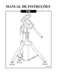
AZ-EQ5 GT Mount
Standard Tripod
Deluxe Pier Tripod
280814V1
Copyright © Sky-Watcher
CONTENT
PART I : SETTING UP THE AZ-EQ5 GT MOUNT
1.1 Setting Up The Tripod ...............................................................................................3
1.2 Putting On The AZ-EQ5 GT Mount ............................................................................3
1.3 Installing The Counterweights ..................................................................................5
1.4 Installing The Telescope ...........................................................................................5
1.5 Balancing The Mount ................................................................................................6
PART II : USING THE AZ-EQ5 GT MOUNT
2.1 Manually Rotating The Mount ..................................................................................7
2.2
2.3
2.4
2.5
Using The Dials ........................................................................................................7
Adjusting The R.A. Axis’s Elevation .........................................................................8
Setting The AZ-EQ5 GT Mount to Alt-azimuth Mode ...............................................9
Installing a Secondary Telescope .........................................................................10
PART III : POLAR ALIGNMENT
3.1 Preparation ........................................................................................................... 12
3.2 Alignment ..............................................................................................................13
3.3 The Orientation of The Polaris ................................................................................14
3.4 Calibrate The Polar Scope ........................................................................................14
PART IV : ELECTRONIC CONTROL INTERFACE
4.1 Control Panel ........................................................................................................16
4.2 Panel Interface Components ................................................................................16
4.3 Pinout of The Interfaces .........................................................................................17
4.4 Power Supply Requirements .................................................................................17
PART V : OTHER AZ-EQ5 GT MOUNT FEATURES
5.1 Auxiliary Encoder Function ...................................................................................18
5.2 Permanent Periodic Error Correction ....................................................................18
5.3 Batch Exposures Function ....................................................................................18
APPENDIX I : SPECIFICATIONS
Dimensions ..................................................................................................................19
Specifications ...............................................................................................................19
Note: The 1 2 3 signs on the diagrams are not related to the Chapter Steps 1. 2. 3.
2
PART I : SETTING UP THE AZ-EQ5 GT MOUNT
1.1 Setting Up The Tripod
For Standard Tripod
1. Fully expand the three legs of the standard tripod on level ground.
2. Locate the locking clamps on the legs and turn counter-clockwise to unlock them to extend
the tripod legs (Fig.1.1a).
3. Extend the legs to desired height. Make sure the tripod top is level and then lock the
clamps.
For Pier Tripod
1. Fully unfold each leg with the pier tripod lying down. Use the thumb screws to secure the
legs firmly, then let the pier tripod stand on a level ground (Fig.1.1b).
2. Locate the locking clamps on the legs and turn counter-clockwise to unlock them to extend
the tripod legs. Extend the legs to desired height, make sure the pier top is leveled and
then lock the clamps (Fig.1.1a).
Clamp
Thumb
Screw
Fig. 1.1a
Fig. 1.1b
1.2 Putting On The AZ-EQ5 GT Mount
1. Loosen the two azimuth adjustment knobs on the AZ-EQ5 GT mount until there is sufficient
space between the two knob screws(Fig. 1.2a).
*
*
*
1
Dowel
Azimuth Adjustment Knobs
Fig. 1.2a
2
3
Fig. 1.2b
3
1
Primary
Locking
Shaft
3
2
Fig. 1.2c
PART I: SETTING UP THE AZ-EQ5 GT MOUNT
2. Align the metal dowel on the tripod top with the gap between
the two azimuth adjustment knobs; then put the mount on
the tripod top(Fig. 1.2b, Fig1.2d).
3. Once the mount is seated, slightly tighten the two azimuth
adjustment knobs.
4. FOR USING A STANDARD TRIPOD, while supporting the
mount with one hand, gently push the primary locking shaft
up against the underside of the mount and turn the shaft
counter-clockwise to secure the mount to the tripod top.
Tighten the shaft with the knurled knob on the primary locking shaft (Fig. 1.2b); then slide the accessory tray along the
primary locking shaft until its three tips push against the tripod legs and secure the tray with the washer and the locking
knob. (Fig. 1.2c)
5. FOR USING A PIER TRIPOD, while supporting the mount
with one hand, use the tumb screw on the flexible shaft to
secure the mount to the tripod top. (Fig. 1.2d)
6. Use the bubble leveler (Fig. 1.2e) on the mount to level the
mount by adjusting the length of the tripod legs.
1
Dowel
Flexible
Shaft
2
Fig. 1.2d
Warning: The accessory tray of a standard tripod ensures that
the tripod legs are firmly expanded, which prevents the tripod
from accidentally tipping over. When using the AZ-EQ5 GT
mount on a standard tripod, an accessory tray should always be
used to ensure stability.
Bubble
Leveler
Fig. 1.2e
4
PART I: SETTING UP THE AZ-EQ5 GT MOUNT
1.3 Installing The Counterweights
1. Loosen the two bolts that locks the counterweight rod and gently pull out the counterweight
rod. Re-tighten the two bolts to secure the counterweight rod in place. (Fig. 1.3a)
2. Loosen the R.A. clutch wheel, and rotate the R.A. Axis until the counterweight rod is pointing towards the ground. (Fig. 1.3b)
3. Remove the threaded cap from the end of the counterweight rod.
4. The AZ-EQ5 GT mount comes with a 120mm counterweight rod extension, which can be
installed at this point if necessary. Ensure the extension is tightly secured before installing
counterweights. (Fig. 1.3c)
5. Loosen the counterweight’s thumb screw and slide the counterweight onto the counterweight rod. Re-tighten the thumb screw to secure the counterweight on the rod.
6. Finish by putting the threaded cap back in place(Fig. 1.3d).
Locking Bolts
Loosen
Lock
R.A.
Clutch
Wheel
Fig. 1.3a
Fig. 1.3b
1
Thumb
Screw
2
Fig. 1.3c
Fig. 1.3d
1.4 Installing The Telescope
1. Before installing a telescope, ensure:
•
•
•
The counterweight rod is pointing towards the ground.
All counterweights have been moved to the end of the counterweight rod.
The R.A. Axis is secured by tightening the R.A. Clutch.
2. Release the Dec. clutch wheel and rotate the Dec. axis until the two thumb screws on the
saddle are facing upward and the dovetail groove is leveled (Fig. 1.4). Tighten the Dec.
clutch again.
5
PART I: SETTING UP THE AZ-EQ5 GT MOUNT
Thumb Screws
Saddle
Lock
Dec. Clutch Wheel
Loosen
Fig. 1.4
3. Loosen the two knobs on the saddle until the space in the dovetail grooves is slightly wider
than the width of the dovetail bar on the telescope.
4. While holding the telescope horizontally, seat or slide the dovetail bar of the telescope to
the groove of the saddle.
5. Tighten the two thumb screws to secure the dovetail bar in the groove.
Warning: Keep supporting the telescope until you are sure that it has been firmly attached to
the saddle.
1.5 Balancing The Mount
Once the counterweight, telescope, and accessories tray have been installed, the mount
should be balanced to reduce stress on the motor drive system, as well as to ensure smooth
and accurate operation.
1. Loosen the R.A. Clutch and rotate the R.A. Axis until the counterweight rod is parallel to
the ground. Tighten the R.A. Clutch.
2. Loosen the Dec. clutch and rotate the Dec. axis until the telescope is parallel to the ground.
Tighten the Dec. clutch.
3. Loosen the thumb screws on the counterweights.
4. Hold the counterweight rod with one hand, release the R.A. Clutch and adjust the counterweights along the rod until the mount is able to remain stationary without support. Tighten
the thumb screws on the counterweights again.
5. Rotate the R.A. Axis; the mount should remain relatively balanced along different angles.
Once this is confirmed, return the mount to its original position described in Step 1 and
tighten the R.A. Clutch again.
6. Hold the telescope with one hand and release the Dec. clutch.
7. Slowly let go of the telescope and check for any rotational movements. If there is a movement, adjust telescope position with relation to the tube rings and saddle. The final position of the telescope should remain stationary without support.
6
PART II : USING THE AZ-EQ5 GT MOUNT
2.1 Manually Rotate The Mount
Refer to the following diagrams:
Lock
Loosen
Dec. Clutch Wheel
Lock
R.A. Clutch
Wheel
Loosen
Fig. 2.1a
Fig. 2.1b
1. Release the R.A. clutch wheel to manually rotate the R.A. Axis (Fig. 2.1a).
2. Release the Dec. clutch wheel to manually rotate the Dec. axis (Fig. 2.1b).
3. Both the R.A. clutch wheel and the Dec. clutch wheel should be tightened when driving the
mount with the internal motors.
2.2 Using The Dials
As displayed below, the AZ-EQ5 GT mount features a R.A dial and a Dec. dial.
Locking
Screw
Locking
Screw
R.A. Dial
Dec. Dial
Fig. 2.2a
Fig. 2.2b
1. Before using the dials, they need to be calibrated: Point the telescope towards a known
coordinate (R.A.-Dec. coordinates or azimuth-altitude coordinates). Loosen the two locking screws on the dials to turn and let the dials read the known coordinates, then tighten
the locking screws again.
2. Once the dials are calibrated, the mount can either be motor-driven or moved manually to
specified coordinates by referring to the dial readings.
7
PART II: USING THE AZ-EQ5 GT MOUNT
3. The R.A. dial features three different scales: the lower scale is used to indicate the right
ascension in Equatorial mode when mount is operating in the Southern Hemisphere; the
middle scale is used to indicate the right ascension in Equatorial mode when operating
in the Northern Hemisphere; the upper scale is used to indicate the azimuth angle when
operating in Alt-azimuth mode.
4. The lower scale of the Dec. dial is divided into four quadrants of 90-degree scales, used
to indicate the declination (when mount is operating in Equatorial mode) or altitude angle
(when operating in Alt-azimuth mode). Users should use the proper segment when calibrating the Dec. dial.
2.3 Adjusting The R.A. Axis’s Elevation
1. Loosen the fork thumb screw located on the sidewalls of the mount (Fig. 2.3a).
Fork
Thumb
Screw
Fig. 2.3a
2. Push in the spring loaded handle to engage the handle with latitude jack (Fig. 2.3b), then
turn the handle left or right to change the elevation of the RA axis to a specified angle by
referring to the latitude scale on the right side of the mount (Fig.2.3c). When the handle
reaches the left or right limits, release the handle to change its orientation for the next
jacking.
Indicator
1
Latitude
Scale
Spring
Loaded
Handle
Latitude Jack
Raise
Lower
2
Fig. 2.3b
Fig. 2.3c
8
PART II: USING THE AZ-EQ6 GT MOUNT
3. Engage the fork thumb knob.
Note: It is normal to have slight elevation play on the AZ-EQ5 GT mount. The mount relies on
the gravity of its payload and its own weight to stay firm. Because of this, it is recommended
to end the elevation adjustment with an upwards movement. Whenever there is an upwards
over-adjustment, lower the elevation first, and then jack the mount upwards again.
2.4 Setting The AZ-EQ5 GT Mount to Alt-azimuth Mode
90 Degree
Fork
Thumb
Knob
Alt-Az Mode
Locking
Bolt
Fig. 2.4a
Fig. 2.4b
1. Refer to Section 2.3 to ajust R.A. axis’s elevation.
2. Use caution when the latitude indicator is close to 90 degree. Do not turn the spring loaded handle further when you feel it is blocked because it means that the R.A. axis has
reached the factory-calibrated position for Alt-azimuth mode. TURNING THE HANDLE FORCEFULLY WILL DAMAGE THE MOUNT.
3. Tighten the Alt-Az mode locking bolt (Fig. 2.4a) to secure the R.A. axis to this position for
Alt-azimuth mode operation. Use a 5mm Allen wrench to secure the bolt if necessary.
4. Tighten the fork with the thumb screw.
5. To restore the mount to Equatorial mode, loosen the fork tightening knob first, then FULLY
release the Alt-Az mode locking bolt (NEVER FORGET TO DO THIS). Use the jack handle
to lower the elevation to the desired angle.
9
PART II: USING THE AZ-EQ5 GT MOUNT
Note:
• In any case, DO NOT TURN THE HANDLE FORCEFULLY.
• The telescope should be mounted in a way so that it is on the right-hand side of the mount
when it points forward.
• When switching between Alt-azimuth/Equatorial modes, be sure to remove all counterweights and telescope from the mount first to avoid damage to the Mount’s latitude adjustment mechanisms.
• It may be more difficult to balance the R.A. (or Azimuth) axis in Alt-azimuth mode. Here are
the balancing steps recommended for Alt-azimuth mode:
»» Balance the payload and counterweights in equatorial mode and mark the position of the
counterweights.
»» Unload the payload and counterweights to set the mount in Alt-Azimuth mode.
»» Re-load the mount again by installing the counterweight at the marked position.
2.5 Installing a Secondary Telescope
A secondary telescope saddle can be installed at the end of the AZ-EQ5 GT mount’s counterweight rod for the mounting of a secondary telescope.
Allen Screw
Counterweight
Rod Locking
Knob
Vertical-adjustment
Knobs
Allen
Wrench
Fig. 2.5a
Fig. 2.5b
1. Slide the counterweight rod out and rotate it so the flat cutting surface at the end of the rod
is facing up, then lock the rod with the locking knobs.
2. Loosen the Allen screw on the saddle’s silver ring and push the saddle onto the counterweight rod, as shown in Fig. 2.5a. Align the Allen screw to the flat surface on the counterweight rod.
10
PART II: USING THE AZ-EQ5 GT MOUNT
3. Use a 5mm Allen wrench to secure the saddle to the counterweight rod with the Allen
screw in the central hole of the saddle (Fig. 2.5b). Also tighten the Allen screw on the silver
ring with the same wrench.
4. Tighten the Dec. clutch, and then install the secondary telescope on the secondary saddle.
The secondary telescope and its saddle should be situated to the left of the mount when
the telescope points forward.
5. Loosen the counterweight rod’s two locking knobs to test the balance of the secondary
telescope. Adjust the position of the telescope in its tube rings or the dovetail bar’s position
in the groove of the saddle until the telescope is balanced. Tighten the knobs again.
6. Loosen the Dec. clutch to test and balance the telescope mounted on the primary saddle.
Then tighten the Dec. clutch again.
7. Loosen the counterweight rod’s locking knobs and rotate the secondary telescope vertically until it points in the same direction as the main telescope. Lock the knobs again.
8. Aim the main telescope at a distant object, and then adjust the two vertical adjustment
knobs(Fig. 2.5a) on the secondary saddle to point the secondary telescope to the same
horizontal level of the distant object.
Note:
• It is recommended to use the secondary saddle only when the AZ-EQ5 GT mount is configured in Alt-azimuth mode.
• There is no mechanism on both the primary saddle and the secondary saddle for aligning the two telescopes in azimuth direction. User has to find a proper way to eliminate the
azimuth deviation.
• The 120mm counterweight rod’s extension cannot be used with the secondary saddle.
11
PART III : POLAR ALIGNMENT
Prior to operating the AZ-EQ5 GT mount in equatorial mode for astrophotographic, it must be
polar aligned. The SynScan hand control provides a high accuracy polar alignment routine after
a 2-Star or 3-Star alignment. Please refer to the SynScan hand control manual for detail instructions.
An optional polar scope kit is also available from Skywatcher for quick polar alignment. This
chapter describes how to use a polar scope to polar-align an AZ-EQ5 mount.
3.1 Preparation
1. Setup the AZ-EQ5 GT mount (Refer to PART I : SETTING UP THE AZ-EQ5 GT MOUNT). It is
recommended to load the mount with the telescope and counterweights prior to polar
alignment.
2. Loosen the two locking knobs to remove the bubble leveler (Fig. 3.1a) and replace it with
the polar scope kit. Attach the polar scope illuminator to the front of the polar scope (Fig.
3.1b).
3. Point the polar scope to the direction of the North Pole (For Northern Hemisphere observing) or South Pole (For Southern Hemisphere observing). Set the R.A. axis’s elevation to
the local latitude (Refer to 2.3 Adjusting the R.A. Axis’s Elevation)
Locking Knobs
Battery Cap
Bubble Leveler
Polar Scope
Illuminator
Polar Scope Kit
Fig. 3.1a
Fig. 3.1b
4. Tighten the battery cap to turn on the power of the polar scope illuminator.
5. Verify whether the polar scope is aligned with the R.A. Axis (Refer to section 3.4 Calibrate
the Polar Scope).
6. Find out the proper orientation of Polaris in the polar scope. (Refer to 3.3 The Orientation
of the Polaris).
12
PART III: POLAR ALIGNMENT
3.2 Alignment
2020
2028
0
2032
2024
9
NCP
SCP
2012
Spring
Loaded
Handle
3
2016
3
ans
Oct
6
Place the four stars
in the Asterism here
(Southern Hemisphere)
Azimuth
Adjustment
Knobs
Fig. 3.2a
Fig. 3.2b
Once the polar scope is illuminated, the pattern in the above figure (Fig. 3.2a) should be visible
in the field of view (FOV) of the polar scope. If the image appears blurred, rotate the knurled
ring of the polar scope’s eyepiece to focus.
1. For observing in Northern Hemisphere: Find the Polaris (The brightest star near the
North Celestial Pole) in the polar scope; then use the spring loaded handle and the two azimuth adjustment knobs to move the Polaris to the proper position in the FOV of the polar
scope (Refer to the upcoming section “The Orientation of Polaris in Polar Scope”).
The Polaris’s orbit around the NCP(north celestial pole) changes gradually. The 3 central
circles in the polar scope pattern are the obits for year 2012, 2020 and 2032. Users should
refer to these circles and the current year to put the Polaris at the proper radius.
2. For observing in Southern Hemisphere: In the FOV of the polar scope, locate the 4 dim
stars (Around Magnitude 5 to 6) which form the pattern like the “Octans” drawing in the
polar scope (refer to Fig. 3.2a). Loosen the R.A. clutch and rotate the R.A. axis to align the
orientation of the “Octans” drawing to the 4 stars. Then use the spring loaded handle and
the azimuth adjustment knobs to move the 4 stars to the 4 small circles of the “Octans”
drawing.
13
PART III: POLAR ALIGNMENT
3.3 The Orientation of The Polaris:
As the Polaris is not located exactly at the North Celestial Pole, we can see it orbits the North
Celestial Pole in a polar scope. The central circles seen in Fig. 3.2a is a representation of the
Polaris’ orbit around the North Celestial Pole. When polar aligning the AZ-EQ5 mount, it is
necessary to determine the orientation of the Polaris on the circle. We can use the following 2
methods to get the orientation:
1. Locate both the Polaris and the star Kochab in the sky. The direction from the Polaris to
the Kochab can be used as an approximation of the orientation of the Polaris in the polar
scope. Put the Polaris at the same direction on the large central circle in the polar scope
to finish the polar alignment.
2. At the end of the initialization of the SynScan hand control, after entering the proper local
longitude, latitude, date, time, and daylight-saving time, the SynScan hand controller will
display the message: “Polaris Position in P.Scope=HH:MM”. Imaging the circles in Fig.
3.2a as a clock’s face with 12:00 at the top, with the current time pointing to the “HH:MM”.
The orientation of the hour hand of the clock represents the orientation of the Polaris in the
polar scope. Put the Polaris in the same orientation on the large circle to finish the polar
alignment.
Out of the two methods above, the orientation given by the SynScan hand controller is the
most accurate.
3.4 Calibrate The Polar Scope
The polar scope must be calibrated to ensure accurate polar alignment. The following steps
will outline how to calibrate the polar scope:
Step1 Align Polar Scope’s Optical Axis with The Center of The Pattern
1. Put a distant fixed point object at the center of the reticle in the polar scope’s FOV with the
azimuth adjustment knobs and the spring loaded handle (Fig. 3.2b).
2. Loosen the polar scope locking bolt (Fig. 3.4a).
2
3
Adjustment
Screws
3. Rotate the polar scope for 180 degree, then tighten
the locking bolt.
4. If the the point object is still at the center of the reticle,
there is no need for further adjustment.
5. If the object is off the center, adjust the three adjustment screws with a 1.5mm Allen key to eliminate the
1
offset by half. When making the adjustment, loosen
Locking bolt
one screw for 1/4 turn each time, and then tighten the
other two screws.
6. Repeat the above operaton until the point object stay
at the center when rotating the polar scope.
Fig. 3.4a
14
PART III: POLAR ALIGNMENT
Step2 Align Vertical Line of The Pattern
1. Loosen the locking knobs in Fig. 3.1a, level the bubble leveler on the polar scope kit, then
tighten these knobs again.
2. Point the polar scope to a distant object which has a verticle reference line.
3. Loosen the locking bolt in Fig. 3.4a, rotate the polar scope to set the 0-6 line in the polar
scope pattern parallel to the verticle reference of the object.
4. Tighten the plar scope locking bolt in Fig. 3.4a again.
Step3 Align Polar Scope’s Optical Axis with AZ-EQ5’s R.A. Axis
1. Put a distant fixed point object to the center of the reticle in the polar scope’s FOV with the
azimuth adjustment knobs and the spring loaded handle (Fig. 3.2b).
2. Loosen the R.A. clutch and rotate the R.A. axis for 180 degree..
Adjustment
Screws
3. If the the point object is still at the center of the reticle,
there is no need for further adjustment.
5. If the object is off the center, adjust the 6 adjustment screws (Fig. 3.4b) on the polar scope kit with a
2.5mm Allen key to eliminate the offset by half. When
making the adjustment, loosen one screw for 1/4 turn
each time, and then tighten the other two screws.
6. Repeat the above operaton until the point object stay
at the center when rotating the polar scope.
Fig. 3.4b
15
PART IV : ELECTRONIC CONTROL INTERFACE
4.1 Control Panel
The control panel of the AZ-EQ5 GT mount is shown below:
Fig. 4.1a
Fig. 4.1b
Fig. 4.1c
4.2 Panel Interface Components:
POWER: This is an outlet from which the mount and the hand control get power
supply. To connect to a power supply, align the index on both the plug of the cord
and the outlet on the panel, and then insert the plug to the outlet. Tighten the
knurled cap on the plug to secure the plug on the panel.
HAND CONTROL: This RJ-45 8-pins outlet is for connecting the SynScan hand
controller.
AUTO GUIDE: This RJ-12 6-pins outlet is for connecting an autoguider. It is compatible with any autoguider with a ST-4 type interface.
SNAP:These are two stereo outlets for connecting to two cameras’ shutter control
ports. The SynScan hand control can control the cameras to take pictures automatically via these interfaces.
ON/OFF Switch: Turns on and off the power to the mount and hand controller.
Power LED
Power LED: The power LED serves as a power-on indicator and provides other
statuses.
1. Steady on: Power voltage is normal.
2. Slow flashing: Power voltage is low; continuing to operate the mount may damage the battery (if a 12V lead-acid battery is in use).
3. Fast flashing: Power voltage is extremely low; continuing to operate the mount
may damage the battery and the motor controller in the mount.
4. Intermittent one flash: The PPEC training routine has been triggered, but the
controller in the mount has not received the worm index signal and the correction-recoding has not started yet.
16
PART IV: ELECTRONIC CONTROL INTERFACE
5. Intermittent two flashes: The PPEC training routine has been started and the
controller in the mount has received the worm index signal and started to record
the PE correction. When the intermittent two flashes stops, it means the PPEC
training has finished.
6. Intermittent, three flashes: Sidereal tracking with PEC is now enabled.
Dec Motor Scokets: These two sockets are used to connect the Dec motor units
to the main control panel with the provided Dec. motor cable.
USB Port: The USB port connects to an internal USB-to-Serial device (Baud rate
115200bps). It can be used to control the mount directly from a host PC. It is also
used to update the firmware of the motor controller.
4.3 Pinout of The Interfaces:
Internal Circuit
HAND CONTROL
Vpp+
Vpp+
RX(3.3V)
TX(3.3V)
GND
GND
POWER
RADECDEC+
RA+
GND
8
7
6
5
4
3
2
1
TRIGGER
Optoisolator
Control Signal
GND
GND
6
5
4
3
2
1
AUTO GUIDE
SNAP
Fig. 4.3
Note:
• The SNAP port provides two trigger signals to the stereo plug.
For a camera which only needs a
shutter-release signal, either trigger signals will work. For a camera
which requires an extra “Focus”
signal, both signals should be connected properly.
• The camera control cable shipped with the AZ-EQ5 GT mount is for a Canon EOS series
DSLR camera. Cable for other cameras is optional and can be ordered separately from
dealer.
4.4 Power Supply Requirements
• Output Voltage: DC 11V (minimum) to DC 16V (maximum). Voltage not in this range might
cause permanent damage to the motor controller or the hand controller.
• Output Current: 3A for power supply with 11V output voltage, 2A for power supply with 16V
output voltage.
• Do not use an un-regulated AC-to-DC adapter. When choosing an AC adapter, it is recommended to use a switching power supply with 15V output voltage and at least 2A output
current.
• If the power voltage is too low, the motor controller will stop the motors automatically.
17
PART V : OTHER AZ-EQ5 GT MOUNT FEATURES
5.1 Freedom FindTM Function
The AZ-EQ5 GT mount is equipped with auxiliary encoders on both the R.A. axis and Dec.
axis. Therefore, the mount can keep track of its current position even when a user unlocks the
clutches and rotates the mount in R.A. axis and Dec. axis manually.
With this feature, a user can manually operate the mount anytime without worrying about losing the mount’s alignment status. When the user wants to operate the mount with the SynScan
hand control again, no alignment is required and all that is needed to be done is to re-lock the
clutches.
This feature can be enabled or disabled on the SynScan hand controller.
5.2 Permanent Periodic Error Correction
The AZ-EQ5 GT mount is equipped with an index on its R.A. worm. Thus the motor controller
can keep track of the current position of the worm. After a proper PEC training routine, in which
the training data is stored in the motor controller permanently, a user can start the periodic
error correction (PEC) at any time to improve the tracking performance for short focal length
astrophotography. A training process is not required in the next observing session (assuming
that the polar alignment is always accurate). Thus this is a Permanent Period Error Correction
(PPEC). A user can train the mount with manual guiding or auto-guiding. For detailed instructions, please refer to the relevant section in the SynScan hand controller instruction manual.
5.3 Batch Exposures Function
The AZ-EQ5 GT mount is equipped with two SNAP ports which can control the shutter releasing of two cameras. Working with the SynScan hand control’s “Camera Control” function, a
user can take batch exposures when doing astrophotography. Up to 8 groups of “Exposuretime & Frames” combinations can be set on the SynScan hand controller. For detailed information, refer to the SynScan hand control’s instruction manual.
18
APPENDIX I : SPECIFICATIONS
Dimensions:
Equatorial Mode
375
45°
317
178
Alt-azimuth Mode
328
178
354
Standard
Tripod
Ø100
Pier
Tripod
Ø100
840
747
731
900
19
APPENDIX I : SPECIFICATIONS
Specifications:
Product Name
Mount Type
Payload
(Counterweights excluded)
Latitude Adjustment Range
AZ-EQ5 GT Mount
German Equatorial / Alt-azimuth Dual Mode
15 kg
(for Astrophotography)
On a Standard Tripod: 28º to 90º
On a Pier Tripod: 0º to 90º
About ±15 º
7.7 kg
3.5 kg / ea. x 2
Standard Tripod: 1.75-inch stainless steel, 5.6 kg
Pier Tripod: 1.75-inch stainless steel, 6.1 kg
18mm Diameter, Length 162mm + 120mm
DC11~16V 3A
1.8 º Hybrid Stepper Motor
135:1 Worm Drive + 72:12 Timing Belt Drive +
32 Micro-step/1.8º Stepper Motor Drive
810
5184000 Counts/Rev., 0.25 arc-second
4.2 degrees/second
Sidereal rate, solar rate, lunar rate
Alt-azimuth mode or Equatorial mode
0.125X, 0.25X, 0.5X, 0.75X, 1X
1200 Segments Permanent PEC
SynScan
42000+ Objects
Messier, NGC, IC, SAO, Caldwell, Double Star, Variable Star, Named Star, Planets
Up to 5 arc-minutes (RMS)
5144 Counts/Rev., approx. 4.2 arc-minutes
Azimuth Adjustment Range
Weight(Tripod excluded)
Counterweight
Tripod
Counterweight Rod
Power Requirement
Motor
Transmission
Gear Ratio
Resolution
Maximum Slewing Speed
Tracking Rate
Tracking Mode
Auto-guiding Speed
PEC
Hand Controller
Database
Celestial Object Catalog
Pointing Accuracy
Resolution of Aux. R.A./Dec. Axis Encoders
Note: The above specifications may be changed without prior notice.
20
AZ-EQ5 GT Mount