1
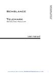
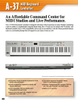
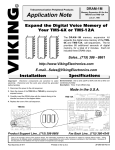
Oberkorn
User
Manual
16 Step Analogue
Sequencer
Analogue Solutions
Oberkorn User Manual
CONTENTS
What is an analogue sequencer? ........................................................................................ 3
That’s all very well (and technical) but what would I use it for? ........................................... 3
ABOUT THIS MANUAL AND ABOUT ANALOGUE GEAR .................................................... 4
SPECIFICATION .................................................................................................................... 4
CVs and Gates – What are They? .......................................................................................... 5
Output Type ............................................................................................................................ 5
CVs...................................................................................................................................... 5
Gates ................................................................................................................................... 6
Basic Hook Up ........................................................................................................................ 7
EXPLANATION OF EACH CONTROL ................................................................................... 7
CV CHANNELS ................................................................................................................... 7
Gate Channels .................................................................................................................. 10
MIDI To Trigger Converter .................................................................................................... 11
Binary Outputs................................................................................................................... 13
Make Oberkorn step in any order! ................................................................................. 14
Changing the MIDI Receive Channel ................................................................................ 14
SEQUENCE CONTROL ....................................................................................................... 14
SETTING ........................................................................................................................... 15
GATING ............................................................................................................................. 17
How Oberkorn Works In More Detail .................................................................................... 18
Introduction........................................................................................................................ 18
How an analogue sequencer works .................................................................................. 19
Some Patch Examples.......................................................................................................... 21
Other mad things to try; ................................................................................................. 21
2
ABOUT THIS MANUAL AND ABOUT ANALOGUE GEAR | Analogue Solutions
Oberkorn User Manual
WHAT IS AN ANALOGUE SEQUENCER?
My definition of an analogue sequencer (since others may slightly disagree) is a device that
will sequentially output a series of varying voltages (CVs) and gate conditions over time.
Sequencers (and when I use this word I will always be referring to analogue ones unless I
state otherwise) will typically be 8-16 steps.
The Oberkorn has 16 steps.
To be a true analogue sequencer the output voltage must be unquantised, otherwise it’s
digital! Digital means discrete steps. Oberkorn’s CV outputs can be swept smoothly from
zero to full output level.
At each step you can change the voltage at the output socket and set whether a trigger /
gate pulse is sent out.
Each step therefore has a potentiometer to change the voltage and a switch to change gate
status.
As the clock runs the sequencer sequentially through each step (usually from one to 16), the
state of the pot’s and switches is output at the sockets.
THAT’S ALL VERY WELL (AND TECHNICAL) BUT WHAT WOULD I USE IT FOR?
Traditionally (back in the 70’s when they where first developed) you would be writing all your
electronic music with them. Melodies, bass lines etc.
But these days you have MIDI sequencers and software that can deal with all that.
But sequencers still provide a different experience when creating music. Don’t think about
‘writing melodies’ with a sequencer. It’s more organic than that. I think the best way to use a
sequencer in your set-up is to hook it up to a synth that has CV/Gate sockets (like our
Telemark, which is perfect for the job). Ideally sync up some sort of drum machine too (we
can supply drum modules and other devices here). Start the sequencer.
Then your tune will evolve. Tweak the sequencer controls and switches, and those of your
synth. Change the drum pattern. After some time, you will just suddenly hit on a perfect
Analogue Solutions | ABOUT THIS MANUAL AND ABOUT ANALOGUE GEAR
3
Oberkorn User Manual
‘groove’. You will have achieved this in a way that you could never do with a software
sequencer. If you have never tried it, search for our YouTube videos for proof.
I have met people who have never used an analogue sequencer. Though they have heard of
them, they have never realized what they could do for them. But then after a short
demonstration, they realize what they have been missing all these years and are instantly
hooked!
ABOUT THIS MANUAL AND ABOUT ANALOGUE GEAR
This manual is not a tutorial on CVs, Synths, Sequencers, Modulars etc. I will try and explain
a little about the terms used and the technology in general. If you want to know
EVERYTHING, then there are plenty of good forums out there and tutorial web sites. So if
there is anything in here you don’t understand either look it up, or just don’t worry. Like any
new subject you will learn other time and pick up information along the way.
SPECIFICATION
CV channels
Channels A and B have a portamento function (labeled Glide).
All three channels have transpose inputs and output level attenuators.
CV range is approx. 0-5v.
Gate channels
2
Gate voltage approx. 10v.
Buttons
Reset to step one
Reset to step 16
Step
Switches
Run/Stop
4
ABOUT THIS MANUAL AND ABOUT ANALOGUE GEAR | Analogue Solutions
Oberkorn User Manual
Gate/Leg
CVS AND GATES – WHAT ARE THEY?
This is not a complete beginner’s guide to analogue synthesizers, but here is a very brief
explanation.
A CV (control voltage) is a varying voltage that can be used to control a parameter of an
analogue synth. Which parameter really depends on the synth. Most synths have at least a
pitch CV input (usually just called CV), and a filter cut-off CV input. These I think are the two
most important. But a good modular will provide CV inputs to control most parameters.
Gate (sometimes called trigger) is typically used to trigger an envelope generator (which
controls the synth’s volume, filter cut-off, and other parameters). Gate can be used to turn
digital switches on and off, or to clock other analogue sequencers.
The beauty of analogue synths and modulars is that there are no rules. So you can use the
CV and Gates how you want. If your synth has a voltage control input socket, then you can
use it. That’s not to say any patch will sound good. Some won’t sound good or even work at
all. So in those cases you’ll need to try something else. That’s the nature of modular synths.
Note:
Though you will hear terms like CV, Gate, V/Oct, Hz/V, Trigger, S-Trig, and they will have
their own general characteristics, there is no true analogue standard.
V/Oct and Hz/V is about the nearest and they usually work as designed, but there are
always occasional incompatibilities or exceptions.
Gates and triggers can be of different voltages and pulse widths. There is no account of
input and output impedances, frequency ranges etc. Some gate outputs might be say 5v or
10v. Some synth may require a gate voltage higher than the controlling device is giving.
So though with modulars and analogues synths you should be able to cross patch with no
problems sometimes things you might try may just not work. This sort of situation may
happen too when you connect a sequencer to a particular synth, or try clocking two devices
together. Sometimes it won’t work. Generally this is rare and whatever you hook up will
usually work. There is usually a work around if there are problems, or you simply just have to
try something else.
Oberkorn seems to work fine with most gear, and I have not heard back many problems.
OUTPUT TYPE
CVS
Analogue Solutions | CVs and Gates – What are They?
5
Oberkorn User Manual
There are two main ‘standards’ (and I use this term loosely) for pitch CV.
V/Oct means Volts Per Octave. This means that a VCO’s pitch will go up one octave for
each volt added to the CV input. 0V (say) would be C, so 1V would be C one octave higher.
This is typically used by;
(old synths) Roland, Moog, ARP, SCI
(new synths) just about everyone – Analogue Solutions, Analogue Systems, Doepfer, etc.
Hz/V means Hertz Per Volt. This means that to go up one octave you must double the
voltage. So (say) C is 3V, then to go up one octave the CV must be 6V.
This was typically used by the old Korg synths (like the MS series), though if I remember
rightly, the monopoly was an exception.
Hz/V is not so flexible as V/Oct. The problems arise when trying to mix Hz/V signals to
change pitch.
Oberkorn outputs a varying voltage on the CV outputs. I am often asked whether its output is
V/Oct, or Hz/V. This question does not really make any sense as such. Oberkorn simple puts
out the voltage that you set on the control. But for pitch control it will ‘feel’ better using V/Oct
synths, which the majority of synths use.
Hz/V and V/Oct only applies to the pitch control of oscillators. For controlling parameters
such as filter cut-off V/Oct or Hz/V does not apply. These ‘standards’ only apply to pitch
control. Parameters such as cut-off just want a varying linear voltage. Once again there is no
standard, but typical ranges are 0-5v, 0-12v, and sometimes bipolar like -12 to +12V.
The range Oberkorn puts out is usually fine for most synths.
GATES
The Oberkorn puts out a positive gate signal. Gate off is 0V, Gate on is 10V. Oberkorn’s
gate signal is strong enough to trigger just about all analogue synths, envelopes, and strong
enough to clock most other analogue sequencers.
There is a complication (isn’t there always?!).
Old Moog and Korg synths typically used a type of Gate called S-Trig. Though I won’t go into
full details, let’s just say that it is a sort of inverted gate signal. Not inverted in polarity, but in
state.
So normally a gate might be 0v for off, and, say, 5v for on.
6
Output Type | Analogue Solutions
Oberkorn User Manual
With S-Trig it is swapped. So, say, 5v for off and 0v for on. (Though in practice S-trig is
implemented in a few different ways by different synths).
I have not tested Oberkorn with many S-Trig synths (since it was designed for the ‘standard’,
more common positive gate synths and because S-trig synths are typically rarer to find). But
I have had reports back that it works fine with Korg MS synths, but inverted (as you would
expect). So to trigger the synth you must set a gate switch to off rather than on!
BASIC HOOK UP
To control a typical analogue synth, the most basic and common way to set up is as follows;
Oberkorn Output
Synth Input
Pitch:
VOLTAGE OUT A
CV (pitch) / Key CV
Gate:
GATE OUT X
Gate / Trig / V-Trig
Cutoff:
VOLTAGE OUT B
VCF
Note: different synths will label their inputs differently.
That’s a basic set-up. If you are new to analogue synths you may just want to stick with that
for starters, just to get used to using the set-up. But more advanced users really should do a
little more than the above! I’ll give more advanced examples later.
EXPLANATION OF EACH CONTROL
The outputs from the CV and Gate channels are found in the box labeled ‘outputs’ on the
front panel.
CV CHANNELS
Analogue Solutions | Basic Hook Up
7
Oberkorn User Manual
Oberkorn has three CV channels A, B and C. They are just about identical, except that C
does not have glide.
Each channel is completely independent form the others, though they will be clocked
together and be of the same sequence length.
So I will just explain one channel (A) and from there you will know what the others are doing.
CV Controls
Each channel has 16 CV controls. When a step is active, the voltage set by the control is
output at its socket.
LED
When a step is active, its LED will be on.
A-LEVEL Control
This is used to set the overall level of the CV signal output at the socket. It’s an attenuator.
A-GLIDE Control
8
EXPLANATION OF EACH CONTROL | Analogue Solutions
Oberkorn User Manual
This is a portamento control (glide/slew). It will smooth out the changes in voltage as each
step is played. Just try it and see! If you appear to get no CV change at the output, you may
have too much glide set.
VOLTAGE OUT A
The CV for channel A comes out of this socket.
TRANSPOSE IN A Socket
The transpose input socket allows you to take a CV from an external device (say an LFO
module, CV keyboard, EG), and mix it with the internal CV generated with the CV controls.
For example;
Put an LFO wave in there and you will add vibrato to the pitch (or wah-wah to filter, tremolo
to VCA).
Use a CV keyboard to transpose the pitch of the sequencer (note transpose inputs are not
calibrate beyond 1% so scaling may be an issue).
Analogue Solutions | EXPLANATION OF EACH CONTROL
9
Oberkorn User Manual
GATE CHANNELS
There are two Gate channels, X and Y.
Each channel is completely independent form the others, though they will be clocked
together and be of the same sequence length.
Gate Switch (rotary switch)
The 16 gate switches each have four positions.
Position 1: X
In this position there will be a gate signal from the X GATE OUT socket when this step is
played.
Position 2: Y
In this position there will be a gate signal from the Y GATE OUT socket when this step is
played.
Position 3: X+Y
In this position there will be gate signals from both GATE OUT sockets when this step is
played.
Position 4: OFF
In this position there will be no gate signalS from either of the GATE OUT sockets when this
step is played.
GATE OUT X Socket
The gate signal for channel X is output at this socket
10
EXPLANATION OF EACH CONTROL | Analogue Solutions
Oberkorn User Manual
GATE OUT Y Socket
The gate signal for channel Y is output at this socket
MIDI TO TRIGGER CONVERTER
Oberkorn has a completely independent MIDI to Trigger converter (MIDI-Trig). It is NOT a
MIDI to CV converter.
It is used to enable you to sync Oberkorn to MIDI.
It has three sections. Binary control, Triggers, Clock, which will be explained later.
The MIDI-Trig section is in the box labeled ‘midi’ on the front panel.
On the rear panel are a MIDI In and MIDI Thru sockets.
MIDI In
Connect your MIDI keyboard or MIDI sequencer here, to control the MIDI-Trig.
MIDI Thru
Analogue Solutions | MIDI To Trigger Converter
11
Oberkorn User Manual
This is just a copy of the MIDI coming into the In socket. Use it to daisy chain up other MIDI
gear.
CK (clock)
If Oberkorn is receiving MIDI Sync signals, then the CK socket will output clock pulses. This
is one way to sync up the Oberkorn to MIDI sequencers, but it is the least flexible. Use the
trigger sockets.
T1 / T2 / T3 / T4 / T5
Note: T3-5 are on the rear panel.
Oberkorn offers five MIDI to Trigger converters. These convert certain MIDI note on/offs into
analogue gate pulses. These can then be used to clock Oberkorn, or trigger other analogue
devices (such as our drum modules, sequencers, EGs).
Trigger
MIDI Note
T1
E
T2
F
T3
F#
T4
G
T5
G#
As I write this, I forget the exact MIDI note number. It’s just above Middle C!
Normally you would use these five triggers to trigger other analogue modules you may own,
like envelopes.
You can also use them to clock analogue sequencers, including Oberkorn.
MIDI Sync
The CK socket can be used for MIDI sync. If your MIDI sequencer is transmitting MIDI Sync,
then the CK socket will output 16ppqn pulses. These can be used to clock the Oberkorn. To
do this you must patch the CK socket to IN clock input. Put the run stop switch to EXT.
Reset Oberkorn to step 16. Connect your MIDI source (sequencer etc) OUT to Oberkorn’s
MIDI In.
When you hit play on your MIDI sequencer Oberkorn should run.
12
MIDI To Trigger Converter | Analogue Solutions
Oberkorn User Manual
Due to the limitations of the MIDI specification of SYNC messages, it is the least effective
method and least flexible method of sync. The best way to sync Oberkorn to a MIDI
sequencer is to use one of the Trig sockets.
e.g. patch socket T1 to Oberkorn clock input IN to use T1 as a clock source. The run/stop
switch must then be set to EXT (external clock).
Now, what you do to clock Oberkorn is to program a string of MIDI notes (E because you are
using the trigger T1).
Each time E is played Oberkorn will advance one step. Normally you would program a string
of 16th notes when your MIDI sequencer is playing in 4/4 time.
But, here’s the beauty of this system and Oberkorn. You do not have to stick to convention
and only string 16ths. By programming any pattern of Es you can do the following;
Swing/Shuffle/Groove
By retarding the timing of even numbered 16th notes. In fact any groove pattern can be
written.
Muting Oberkorn
By muting the control track on your MIDI sequencer, no more ‘E triggers’ are sent by the
Oberkorn’s MIDI-Trig unit. This way you can stop and start Oberkorn mid-MIDI sequencer.
This is something you can’t do when synching via MIDI Sync alone (using the CK socket).
BINARY OUTPUTS.
Sockets b0/1/2/3 provide a binary output from 16 MIDI notes.
As each of 16 MIDI keys are pressed, numbered from 1 to 16 (well, 0 to 15 actually), this is
converted to four bit binary and sent out of the binary sockets.
The 16 keys start from C (just below middle C) then the next 16 keys.
The binary sockets are a little confusing but I’ll do my best to explain.
The best way is to start with an example.
Stop the sequencer. Press Reset to 1, so the sequencer is on step 1.
Connect a MIDI keyboard to Oberkorn, and the MIDI channels up correctly.
Next, using four patch leads, connect the four binary outputs b0/1/2/3 in the ‘midi’ box on the
front panel to the four binary input scokets b0/1/2/3 in the ‘sequencer control box.
Now starting with note C, press this MIDI key then the next 15. You should see the step
number of the sequencer change as you go up.
You can see from this that you can control, via MIDI notes, which step Oberkorn is on.
Analogue Solutions | MIDI To Trigger Converter
13
Oberkorn User Manual
MAKE OBERKORN STEP IN ANY ORDER!
You could therefore use a MIDI sequencer to write any combination of these 16 notes to
make Oberkorn step in any order you wish and in any direction. Forward, backwards,
pendulum, even steps only, first eight steps only, etc. Any way you wish!
Note: using this method will note create ‘normal’ gate outputs. I’ll explain more later. But you
can create ‘normal’ gates using the MIDI-Trig unit (sockets T1-5).
CHANGING THE MIDI RECEIVE CHANNEL
To change the MIDI channel, first connect a MIDI keyboard to Oberkorn.
Set the transmit channel on the keyboard to the channel you want to use.
Press and hold the MIDI Program button PROG. Whilst holding this down press a key on
your MIDI keyboard. Release the PROG button.
Oberkorn will set to receive on the same channel as the keyboard. The channel number is
stored in non-volatile memory.
Default is (usually) channel one.
SEQUENCE CONTROL
In the front panel box labeled ‘sequence control’ you will find the controls and sockets that
control the sequencer’s stepping/running.
TEMPO control
This control sets the speed of the internal clock.
IN Socket
14
SEQUENCE CONTROL | Analogue Solutions
Oberkorn User Manual
If you want to sync Oberkorn from an external clock source, use this socket. You can use
one of Oberkorn’s MIDI-Trig outputs here to allow you to clock from a MIDI note.
You might want to use the clock output from another analogue sequencer here, or even the
square wave output from an LFO.
Oberkorn as a VCO
Note: you can clock Oberkorn using the square wave from a VCO! This was Oberkorn will
step at audio frequencies. Take a CV output into your audio mixer (watch the signal levels)
then use the 16 CV controls to adjust the shape of the waveform!
OUT Socket
Which ever clock source is selected using the Run/Stop switch, is thru’ed to the out socket.
If the Run/Stop switch is left, then the internal clock signal is sent out.
If the Run/Stop switch is right, then the external clock signal is sent out.
If the switch is in the centre (off) then no signal is sent out.
Daisy Chain Synchronization
Use this socket to daisy chain and sync other analogue sequencer’s to Oberkorn.
CV Socket
The internal clock speed can be changed via an external CV.
Rub/Stop will have to be set left (INT) so the internal clock is used as a sync source.
Make sure the TEMPO control is set below maximum.
Plug an external CV into the CV socket, for example, output from an envelope or LFO.
The clock speed will change according to the input voltage.
Weird?
Why not try using one of Oberkorn’s own CV outputs to change its own clock speed! I have
not tried this. Could be interesting!
SETTING
The function of the controls in the setting box on the front panel are explained here.
Analogue Solutions | SEQUENCE CONTROL
15
Oberkorn User Manual
LED
The LED will light up to show the activity of the clock source selected with the Run/Stop
Switch
Run/Stop Toggle Switch
The three way toggle switch selects clock source.
Left / INT
Internal clock is selected. Speed controlled with the TEMPO control.
Centre
In the position the sequencer will not run (stop).
Right / EXT
Selects the clock signal present at the IN socket as clock source.
->1 Reset to Step One
Pressing this will reset the sequencer to step one. Normally you would stop the sequencer
first.
->16 Reset to Step 16
Pressing this will reset the sequencer to the last, 16.
Why would you want to do this? Well, actually, reset to step one as found on just about all
other sequencers is just about useless, and I’ll explain why.
If the sequencer is stopped, then started, then the first step to play is not in fact the current,
initial step, that the sequencer was on when it was stopped, but the next step.
This is normal behavior of all true analogue sequencers (do to the way these type of
sequencers are designed using logic chips).
With all other sequencers of this type I have encountered, it means that if you first reset the
sequencer to step one then the first step that always plays initially when you press start is
always step two!
So to overcome this you would have to press STEP up to 15 time to manually put the
sequencer to step 16, so that when you press start, it starts on step one.
16
SEQUENCE CONTROL | Analogue Solutions
Oberkorn User Manual
Oberkorn overcomes this by having a reset to 16 button. This way Oberkorn correctly starts
on step one.
Note: When manually stopping and starting the sequencer using the toggle switch, switch
note may cause the sequencer to skip a couple of steps. This will not happen when you use
a MIDI note to sync Oberkorn (when patching a T MIDI to Trigger socket to the clock Input
socket).
+1 Step
Usually used when the sequencer is stopped. Pressing this will advance the sequencer by
one position. You would normally use this to audition each step individually, for example to
trim each CV setting.
GATING
The Last control box is a little hard to explain!
GATE / LEG (legato)
When this switch is set to gate, then each gate signal is discrete individual 16ths.
When set to LEG the gates are added together. When two or more gate switches in a row
(ones next to each other)
Analogue Solutions | SEQUENCE CONTROL
17
Oberkorn User Manual
GATING X / Y
This one’s hard to explain in writing. I will give a very basic explanation here, but more detail
later.
If you don’t understand this then don’t worry! Try reading the more detailed explanation. If
that fails, watch the YouTube demo’s or must play around.
Basically to get gate outputs Oberkorn needs two signals. The clock signal and the condition
of the gate switch.
If the gate switch is ON and the clock signal is HIGH (on) then you will get a gate signal out.
If either the gate switch is OFF or the clock signal is LOW (off) then there will be no gate
signal out.
Both must be high (on).
If you know what AND is in Boolean algebra, then it’s the same thing.
By feeding a clock or gate signal into the GATING inputs (use an LFO square wave, clock,
Gate from a MIDI to CV converter, or a trig from the Oberkorn MIDI-Trig converter) you can
provide your own signal in place of the clock signal to decide how gates are made.
Confusing, so just play around.
HOW OBERKORN WORKS IN MORE DETAIL
INTRODUCTION
The analogue sequencer is quick and easy to use. Plug it in and off you go! That is the
attraction for many people. But what I have done with the Oberkorn is the ‘hack’ the signals
inside to allow for greater control and creativity. The downside is that using the hacked
features is less intuitive unless you have some basic knowledge of logic circuits! If you can
understand these extra features you will get so much more out of it.
I will try my best to explain in a little detail how an analogue sequencer works inside, and
with that knowledge you might better understand how some of the extra Oberkorn features
work.
Do not worry if the results are not exactly what you expect. This is old style modular synth
technology, and half the beauty is the quirky surprising results that you can obtain, often by
accident!
18
How Oberkorn Works In More Detail | Analogue Solutions
Oberkorn User Manual
Very Basic Block Diagram Of An Analogue Sequencer;
HOW AN ANALOGUE SEQUENCER WORKS
The counter counts clock inputs (coming in from the clock in jack or from the internal clock).
The counter counts from 0-15 (and repeats) and puts this out as a 4 bit binary code (google
binary code and any other terms you are not sure about!). This code is basically a way of
representing numbers from 0 to 15 using 4 wires.
This code is fed into the multiplexer/decoder (which I will refer to as the Mux to save on
typing). The mux takes the 4 bit code, and depending on its value, will turn on one of the 16
outputs. So as the code goes up from 0-15 (and repeats), each mux output will turn on (then
off) one after the other creating a “sequencial output” which you can visually see as the
LEDs run from 1-16 (each mux output turning on sequencially).
This output can then be trimmed using the CV controls on the front panel, goes through an
amplifier, mixed with another CV (from the transpose input), and then goes through a slew
circuit (portamento/glide).
The sequencial output also goes through special circuits to create gate outputs which I will
explain separately.
Analogue Solutions | How Oberkorn Works In More Detail
19
Oberkorn User Manual
20
How Oberkorn Works In More Detail | Analogue Solutions
Oberkorn User Manual
SOME PATCH EXAMPLES
No hard and fast rules. Just do what works and what is fun.
OTHER MAD THINGS TO TRY;
Patch a pitch CV output (A, B or C) into clock CV input.
Patch a gate output into either b0, b1, b2, or b3 setting inputs.
SYNC’ING TWO OBERKORNS
Take clock Out of first Oberkorn to clock In of second Oberkorn. Second Oberkorn run/stop
switch should be set to EXT.
SYNC’ING TWO OBERKORNS WITH DIFFERENT RELATIVE SPEEDS
Or you could use one of the b0-b3 setting input/output sockets as a sync signal for the
second Oberkorn. This way the second Oberkorn will run at half speed (or quarter speed,
etc.).
Analogue Solutions | Some Patch Examples
21
Oberkorn User Manual
22
Some Patch Examples | Analogue Solutions