1
Xylon Linux Framebuffer Driver
For Use with Xylon’s Display Controller IP Core –
logiCVC-ML Compact Multilayer Video Controller
User’s Manual
Version: 3.00.a
Xylon-Linux-FrameBuffer_v3_00_a.doc
Xylon Linux FrameBuffer
Driver
User’s Manual
November 14, 2014
Version: v3.00.a
All rights reserved. This manual may not be reproduced or utilized without the prior written permission
issued by Xylon.
Copyright © Xylon d.o.o. logicBRICKSTM is a registered Xylon trademark.
All other trademarks and registered trademarks are the property of their respective owners.
This publication has been carefully checked for accuracy. However, Xylon does not assume any
responsibility for the contents or use of any product described herein. Xylon reserves the right to
make any changes to product without further notice. Our customers should ensure to take
appropriate action so that their use of our products does not infringe upon any patents.
Copyright © Xylon d.o.o. 2014 All Rights Reserved
Page 2 of 27
Xylon Linux FrameBuffer
Driver
User’s Manual
November 14, 2014
Version: v3.00.a
1
INTRODUCTION .......................................................................................................................... 4
2
LOGICVC-ML COMPACT MULTILAYER VIDEO CONTROLLER .............................................. 7
3
XYLON FRAMEBUFFER SOFTWARE DRIVER ......................................................................... 8
3.1
DRIVER VERSIONING .............................................................................................................. 8
3.2
FEATURES ............................................................................................................................. 8
3.3
XYLON FRAMEBUFFER DRIVER ................................................................................................ 9
3.4
OPEN FIRMWARE ................................................................................................................... 9
3.5
SUPPORT FOR MULTIPLE LOGICVC-ML LAYERS........................................................................ 9
3.6
PIXEL CLOCK SUPPORT ......................................................................................................... 11
3.7
KERNEL BOOT ARGUMENTS ................................................................................................... 12
3.7.1 Console and video mode settings ................................................................................... 12
3.7.2 Mapping of physical memory to logiCVC-ML layers ........................................................ 12
3.8
FRAMEBUFFER DRIVER CONFIGURATION ............................................................................... 13
3.8.1 logiCVC-ML core configuration ....................................................................................... 13
3.8.2 Framebuffer Driver configuration .................................................................................... 16
3.8.3 logiCLK clock generator configuration ............................................................................ 16
3.8.4 Video mode selection priority .......................................................................................... 18
3.9
FRAMEBUFFER DRIVER MISCELLANEOUS FUNCTIONALITY ........................................................ 18
3.10 FRAMEBUFFER DRIVER MULTIPLE INSTANCES ......................................................................... 20
3.11 FRAMEBUFFER DRIVER RESOLUTION SETTINGS ....................................................................... 20
3.12 FRAMEBUFFER DRIVER CUSTOM IOCTLS ............................................................................... 21
4
BUILDING XYLON FRAMEBUFFER DRIVER FOR XILINX ARM LINUX KERNEL.................. 22
5
XYLON FRAMEBUFFER DTS SNIPPET ................................................................................... 24
6
REVISION HISTORY ................................................................................................................. 27
Copyright © Xylon d.o.o. 2014 All Rights Reserved
Page 3 of 27
Xylon Linux FrameBuffer
Driver
User’s Manual
November 14, 2014
Version: v3.00.a
1 INTRODUCTION
Xylon’s logicBRICKS library of IP cores optimized for Xilinx® programmable devices includes
graphics logicBRICKS IP cores for full range implementation of 2D and 3D Graphics Processing
Units (GPU) on Xilinx Zynq®-7000 All Programmable SoC and FPGAs.
Depending on graphics requirements, designers can use one or more logicBRICKS IP cores to build
the graphics engine through easy plug-and-play Xilinx Vivado® and ISE® Design Suite design flows.
The minimum GPU configuration requires the logiCVC-ML display controller IP core to interface the
system processor with the LCD or other types of graphics displays.
The logiCVC-ML Compact Multilayer Video Controller supports many advanced graphic features and
enables easy interfacing with different display types. Xylon provides extensive logicBRICKS software
support to enable software developers to work efficiently with popular graphic libraries, widget toolkits
and familiar development tools.
This User’s Manual briefly describes Xylon’s Framebuffer software driver optimized for the logiCVCML display controller IP core and Linux® operating system. The same software driver can be used
with the Android™ operating system.
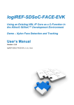
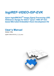
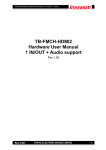
Figure 1: The ZedBoard™ Development Board from Avnet Electronics Marketing Running
Xylon’s 3D Graphics Demo on Linux OS
Linux Framebuffer is a standard Linux driver that abstracts the graphic hardware and allows
application software to access the hardware through a well-defined interface. Software designers can
use it with no need to know anything about the underlying hardware (Xylon logicBRICKS IP cores) in
Xilinx Zynq-7000 All Programmable SoC and FPGA devices.
Copyright © Xylon d.o.o. 2014 All Rights Reserved
Page 4 of 27
Xylon Linux FrameBuffer
Driver
User’s Manual
November 14, 2014
Version: v3.00.a
Where to Get the Xylon Framebuffer Driver?
To get the latest Xylon’s Linux software drivers, please visit https://github.com/logicbricks.
How to Try It?
Xylon Framebuffer driver can be used with any Xilinx FPGA or Zynq-7000 SoC based system
running Linux or Android operating systems. Xylon offers pre-verified reference designs for popular
evaluation kits. Designs include evaluation logicBRICKS IP cores, hardware design files, complete
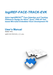
Linux OS image, software drivers, demo applications (Figure 2) and documentation. Please check
Xylon’s Video Gallery web pages (http://www.logicbricks.com/logicBRICKS-IP-Library/VideoGalleries.aspx) to see the demonstrated graphics demo applications.
Available Xylon reference designs:
1) Graphics Engine for the Xilinx ZC702 Evaluation Kit
http://www.logicbricks.com/logicBRICKS/Reference-logicBRICKS-Design/Graphics-for-Xilinx-Zynq7000.aspx
2) Graphics Engine for the Xilinx ZC706 Evaluation Kit
http://www.logicbricks.com/logicBRICKS/Reference-logicBRICKS-Design/Graphics-for-Xilinx-Zynq7000-ZC706.aspx
3) Graphics Engine for the ZedBoard Development Kit from Avnet Electronics Marketing
http://www.logicbricks.com/logicBRICKS/Reference-logicBRICKS-Design/Graphics-for-Zynq-APSoC-ZedBoard.aspx
4) Graphics Engine for the MicroZed Development Kit from Avnet Electronics Marketing
http://www.logicbricks.com/logicBRICKS/Reference-logicBRICKS-Design/Xylon-Advanced-DisplayController-MicroZed.aspx
5) Human Machine Interface (HMI) for the Xilinx ZC702 Evaluation Kit
http://www.logicbricks.com/logicBRICKS/Reference-logicBRICKS-Design/HMI-for-Xilinx-Zynq7000.aspx
Copyright © Xylon d.o.o. 2014 All Rights Reserved
Page 5 of 27
Xylon Linux FrameBuffer
Driver
User’s Manual
November 14, 2014
Version: v3.00.a
Additional Xylon logicBRICKS GPU Software Support
logicBRICKS IP cores can be delivered with software drivers for the most popular operating
systems: Linux, Microsoft® Windows® Embedded Compact, Android and QNX®.
For use with the Linux operating system Xylon also offers:
Direct Frame Buffer (DirectFB) - a thin library that provides hardware graphics acceleration,
input device handling and abstraction, integrated windowing system with support for
translucent windows and multiple display layers
OpenGL® ES 1.1 - a royalty-free, cross-platform API for full-function 2D and 3D graphics
on embedded systems - including consoles, phones, appliances and vehicles.
For more information about Xylon software support for graphics logicBRICKS IP cores, please visit:
http://www.logicbricks.com/logicBRICKS/Reference-logicBRICKS-Design/OS-IP-Core-Support.aspx
What logicBRICKS IP cores version are supported by this Framebuffer SW driver?
Please check Table 1 in paragraph 3.1 Driver Versioning.
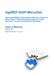
Figure 2: Screenshots from Graphics Demos Provided with Xylon logicBRICKS Reference
Designs
Copyright © Xylon d.o.o. 2014 All Rights Reserved
Page 6 of 27
Xylon Linux FrameBuffer
Driver
User’s Manual
Version: v3.00.a
November 14, 2014
2 LOGICVC-ML COMPACT MULTILAYER VIDEO CONTROLLER
The logiCVC-ML IP core is an advanced display graphics controller for LCD
and CRT displays, which enables an easy video and graphics integration into
embedded systems with Xilinx Zynq-7000 All Programmable SoC and FPGAs.
This IP core is the cornerstone of all 2D and 3D GPUs. Though its main
function is to provide flexible display control, it also includes some hardware
accelerated display functions: alpha blendings, panning, buffering of multiple
frames, etc.
Supports all Xilinx FPGA families
Supports LCD and CRT displays (easily tailored for special display types)
64x1 to 2048x2048 display resolutions
Support for higher display resolutions available on request
Supports up to 5 layers; the last one configurable as a background layer
Configurable layers’ size, position and offset
Alpha blending and Color keyed transparency
Pixel, layer, or color lookup table (CLUT) alpha blending mode can be independently set for
each layer
Packed pixel layer memory organization
RGB - 8-bpp, 8-bpp using CLUT, 16bpp Hi-color RGB565 and True-Color 24bpp
YCbCr - 16 bpp (4:2:2) and 24bpp (4:4:4)
Configurable CoreConnectTM PLBv4.6, Xylon XMB or ARM® AMBA® AXI4 memory interface
data width (32, 64 or 128)
Statically and dynamically programmable layer memory base address
Programmable stride
Simple programming due to small number of control registers
Support for multiple output formats:
Parallel display data bus: 12x2-bit, 15-bit, 16-bit, 18-bit or 24-bit
Digital Video ITU-656: PAL and NTSC
LVDS output format: 3 or 4 data pairs plus clock
Camera link output format: 4 data pairs plus clock
DVI output format
YCbCr 4:4:4 or 4:2:2 output format
Supports synchronization to external parallel input
Versatile and programmable sync signals timing
Double/triple buffering enables flicker-free reproduction
Display power-on sequencing control signals
Parametrical VHDL design that allows tuning of slice consumption and features set
Available for Xilinx Vivado IP Integrator and ISE XPS implementation tools
More info in Xylon’s web shop: http://www.logicbricks.com/Products/logiCVC-ML.aspx
Datasheet: http://www.logicbricks.com/Documentation/Datasheets/IP/logiCVC-ML_hds.pdf
Copyright © Xylon d.o.o. 2014 All Rights Reserved
Page 7 of 27
Xylon Linux FrameBuffer
Driver
User’s Manual
Version: v3.00.a
November 14, 2014
3 XYLON FRAMEBUFFER SOFTWARE DRIVER
3.1 Driver Versioning
Version
1.0
1.1
1.2
Supported logiCVC-ML
CORE version
2.05.c
2.05.c
2.05.c, 3.00.a
2.1
3.00.a, 3.01.a, 3.02.a,
3.02.b
3.0
4.00.a, 4.01.a, 4.01.b
NOTES
Initial driver version
Added support for the logiCLK* clock generator
Added support for YUV color space
Added EDID functionality with interface to the ADV7511
V4L2 driver
Supported multiple driver instances
Resolution settings improvements
Support for the logiCVC-ML IP core from version 4.00.a
Support for the logiCLK clock generator IP core moved to
the dedicate logiCLK Linux driver**
Table 1: The Driver History
* Learn more about this auxiliary IP core:
http://www.logicbricks.com/Documentation/Datasheets/IP/logiCLK_hds.pdf
** Contact Xylon
3.2 Features
Xylon Framebuffer Driver is the Linux kernel driver. It supports the following logiCVC-ML display
controller’s features:
Resolutions from 64x1 up to 2048x2048
Up to 5 layers, last configurable as background color (example: video overlaid with an HMI)
Configurable layers’ size and position
Dynamically configurable layers’ address
Alpha blending and Color keyed transparency (Pixel, Layer or Color LUT alpha blending)
Packed pixel layer memory organization
RGB
pixel color depth 8bpp (Color Look-Up Table (CLUT))
16 bits per pixel HiColor RGB 5-6-5
TrueColor 24bpp
YUV
pixel color depth 8bpp (CLUT table with the AYUV8888 only!)
16 bits per pixel (4:2:2)
32 bits per pixel (4:4:4) : memory layout => AYUV8888
Copyright © Xylon d.o.o. 2014 All Rights Reserved
Page 8 of 27
Xylon Linux FrameBuffer
Driver
User’s Manual
November 14, 2014
Programmable and fixed layer memory base address
Double/triple buffering enables flicker-free reproduction
Display power-on sequencing control signals
Pixel clock frequency supported by:
Version: v3.00.a
Si570 10 MHz – 1.4 GHz DSPLL® from Silicon Laboratories (used on the ZC70x board)
logiCLK IP core (Please check the logiREF-ZGPU-ZED GPU Reference Design User’s
Manual, Chapter 6. Video Output Clocking with an auxiliary IP core
http://www.logicbricks.com/Documentation/Datasheets/IP/logiREF-ZGPU-ZED_UM.pdf )
Miscellaneous:
Interfacing the ADV7511 HDMI transmitter V4L2 driver to retrieve EDID parameters and
initialize the logiCVC-ML display controller IP core accordingly to the preferred display
resolution
3.3 Xylon Framebuffer driver
The driver source files are located in the Linux kernel folder drivers/video/fbdev/xylon.
The driver header file is located in the Linux kernel folder include/uapi/linux.
3.4 Open Firmware
The Linux kernel contains Open Firmware (OF) functionality to provide various information and
parameters about specific hardware devices to the OF kernel drivers. These parameters are called
properties and are available to OF kernel driver for usage at loading time. The OF properties are
loaded from Device Tree Blob (DTB) binary file stored in memory by boot loader, waiting on specific
OF kernel driver to use them. The Linux kernel must be configured to support the OF functionality in
order to enable and use the OF properties. Device Tree Source (DTS) file is used as an input to the
Device Tree parsing script located in the Linux kernel tree for generating the DTB file.
The OF functionality is often used in embedded systems based on SoC and FPGA devices, since the
programmable devices can often change internal configuration. When the SoC/FPGA hardware
configuration changes, any hardware parameter can be changed and used by the kernel driver
without the need for recompiling the Linux kernel or Linux kernel driver. If new hardware (SoC/FPGA)
functionality property is added in the kernel driver code and the DTS file, the Linux kernel and the
Linux kernel driver must be recompiled.
3.5 Support for multiple logiCVC-ML layers
Xylon Framebuffer driver supports multiple logiCVC-ML layers. The layer pixel type, blending order
and memory locations are defined by the FPGA design. The driver gets the logiCVC-ML layer
configuration from the DTB file. For details see chapter 3.8.
Copyright © Xylon d.o.o. 2014 All Rights Reserved
Page 9 of 27
Xylon Linux FrameBuffer
Driver
User’s Manual
November 14, 2014
Version: v3.00.a
Xylon Framebuffer driver will create the following Linux kernel device files for each logiCVC-ML layer:
/dev/fb0
/dev/fb1
..
/dev/fbN
N = number of logiCVC-ML layers -1
logiCVC-ML layer is enabled when the /dev/fbN file is opened and disabled when file is closed.
By default, the logiCVC-ML layer 0 (/dev/fb0) is used for the Linux kernel console.
Other layers can be also selected for the Linux kernel console by setting up the “console-layer” DTS
property.
When “console-layer” property is set to e.g. “1” then the logiCVC-ML layer 1 is represented with the
file /dev/fb0 and the other layers will be numbered in sequential order.
Examples:
logiCVC-ML implements four layers and “console-layer” = 0
Layer ordering in the /dev folder:
/dev/fb0 – Layer0
/dev/fb1 – Layer1
/dev/fb2 – Layer2
/dev/fb3 – Layer3
logiCVC-ML implements four layers and “console-layer” = 2
Layer ordering in the /dev folder:
/dev/fb0 – Layer2
/dev/fb1 – Layer0
/dev/fb2 – Layer1
/dev/fb3 – Layer3
Copyright © Xylon d.o.o. 2014 All Rights Reserved
Page 10 of 27
Xylon Linux FrameBuffer
Driver
User’s Manual
Version: v3.00.a
November 14, 2014
3.6 Pixel clock support
Xylon Framebuffer driver supports two pixel clock sources. The Linux kernel configuration menu
enables selection of one of the supported options as follows:
Drivers -> Graphics support -> Frame buffer Devices -> Xylon logiCVC frame buffer support ->
Xylon logiCVC pixel clock:
- Xylon logiCLK pixel clock generator – support for the auxiliary logiCLK IP core that enables
generation of accurate pixel clock frequencies (0.05% tolerance)
- Si570 pixel clock generator – support for the Si570 DSPLL chip mounted on Xilinx Zynq-7000
AP SoC evaluation boards
The pixel clock source configuration depends on the FPGA/Zynq-7000 SoC design. The logiCVC-ML
pixel clock input can be connected to logiCLK auxiliary IP core implemented in the programmable
logic, Si570 clock generator on the ZC70x board, or some external clock source.
Xylon Framebuffer driver support is designed to enable the logiCVC-ML IP core use of external (onboard) or internal (in SoC/FPGA) hardware devices to achieve various advanced driver functionality.
Xylon’s reference designs for Xilinx ZC70x or Avnet Electronic Marketing ZedBoard
evaluation/development kits use Xylon Framebuffer driver support to control on-board external HDMI
transmitter and to drive standard PC monitors. This support can be expanded on as-needed basis.
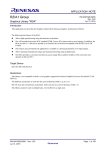
Table 2 shows required pixel clock’s frequencies for several popular display resolutions. Properly
implemented display interface must respect the expected display signals’ timings, which are based on
the requested pixel clock. Wrong pixel clock causes wrong timings on the display interface and, as a
consequence, wrong or missing picture on the display. It is visible from the table that graphic
controller must be able to source different pixel clocks in order to support multiple display resolutions.
Resolution (@60Hz)
Pixel Clock (MHz)
VGA (640x480)
480p (720x480)
WVGA (854x480)
SVGA (800x600)
XGA (1024x768)
WXGA (1280x768)
HD 720p (1280x720)
SXGA (1280x1024)
HD1080p (1920x1080)
25.25
27
32
40
65
68.25
74.25
108
148.5
Table 2: Pixel Clock – Common Video Resolutions
Copyright © Xylon d.o.o. 2014 All Rights Reserved
Page 11 of 27
Xylon Linux FrameBuffer
Driver
User’s Manual
November 14, 2014
Version: v3.00.a
3.7 Kernel boot arguments
3.7.1 Console and video mode settings
Linux kernel console is enabled by the following line in the kernel boot arguments:
console=tty0
Default video VESA video mode can be selected from the kernel arguments; please see
Documentation/fb/modedb.txt for details. Chapter 3.8.4 explains video modes priorities.
video=xylonfb:800x600M-32@60
3.7.2 Mapping of physical memory to logiCVC-ML layers
The physical memory locations for logiCVC-ML display controller IP core’s layers can be
determined dynamically or statically. Based on this selection, the driver will do the following:
- for layers without static address space, driver dynamically allocates layer video memory
- for layers with static address space, driver will use address provided in DTS file
The driver will map the layer address space for the Framebuffer console. logiCVC-ML layers with
statically determined address space must reside outside of the system memory. Dynamically
allocated address space will reside inside the system memory. Statically determined memory space
and system memory space must be separated by limiting system memory to a specific size in the
DTS memory node, as shown by the following examples.
Examples:
Sytem RAM – 1GB:
ps7_ddr_0: memory@0 {
device_type = "memory";
reg = <0x0 0x40000000>;
};
System RAM – 768 MB:
ps7_ddr_0: memory@0 {
device_type = "memory";
reg = <0x0 0x30000000>;
};
The system memory can be also limited by using the kernel parameter “mem=nn[KMG]”, which is
provided as the boot argument.
Copyright © Xylon d.o.o. 2014 All Rights Reserved
Page 12 of 27
Xylon Linux FrameBuffer
Driver
User’s Manual
November 14, 2014
Version: v3.00.a
However, the system memory size handling through the DTS, which is illustrated by above examples,
is the preferred method.
3.8 Framebuffer Driver Configuration
To configure the driver, position in the Linux kernel configuration menu to:
Drivers -> Graphics support -> Frame buffer Devices -> Xylon logiCVC frame buffer support
Choose Xylon logiCVC pixel clock and pick the one that fits to your design.
To configure the amount of system memory reserved for video memory allocation, position in the
Linux kernel configuration menu to:
Drivers -> Generic Driver Options
Choose Size in Mega Bytes (MB) and set the value minimally to the size of video memory used by
the logiCVC-ML.
Example:
Size in Mega Bytes (128)
3.8.1 logiCVC-ML core configuration
The following properties are used for logiCVC-ML configuration. Check the logiCVC-ML Users’s
Manual for detail description.
compatible = "xylon,logicvc-4.00.a";
reg = <0x40030000 0x6000>;
interrupt-parent = <&ps7_scugic_0>;
interrupts = <0 59 4>;
background-layer-bits-per-pixel = <32>;
background-layer-type = "rgb";
display-interface-itu656;
hsync-active-low;
vsync-active-low;
data-enable-active-low;
pixel-data-invert;
pixel-data-output-trigger-high;
readable-regs;
size-position;
pixel-stride = <2048>;
power-delay = <0>;
signal-delay = <0>;
layer_0 {
address = <0x30000000>
buffer-offset = <512>;
bits-per-pixel = <16>;
type = "yuv";
Copyright © Xylon d.o.o. 2014 All Rights Reserved
Page 13 of 27
Xylon Linux FrameBuffer
Driver
User’s Manual
November 14, 2014
Version: v3.00.a
transparency = "layer";
component-swap;
};
layer_1 {
address = <0x30600000>;
bits-per-pixel = <32>;
type = "rgb";
transparency = "pixel";
};
layer_2 {
address = <0x31F50000>;
bits-per-pixel = <8>;
type = "rgb";
transparency = "clut32";
};
layer_3 {
address = <0x3216C000 0xCA8000>;
bits-per-pixel = <16>;
type = "rgb";
transparency = "layer";
};
Specific property description:
- layer_N – layer has its own configuration described with below properties, where N is layer ID in
range 0 – 4
- bits-per-pixel – layer bits per pixel configuration (8, 16, 32). Layer is configured to be used with
specified pixel width in bits. Pixels written to layer video memory must match in size to
configured bits per pixel value.
- background-layer-bits-per-pixel – background layer bits per pixel (8, 16, 32)
If omitted, last available layer is logiCVC standard layer, which has its own video memory of
specific size, color format and specified bits per pixel. If 8, 16 or 32, last available layer is
logiCVC background layer, with only specified bits per pixel value. Available layer ID in range
0 - 3.
- type – layer type (rgb, yuv, alpha)
Layer is configured to be used with specified color space. Pixels written to layer video memory
must match specified color format. Type is set to "alpha" if layer is used only for pixel alpha
values used by layer above. Layer IDs for using layer type alpha are 1 and 3.
- transparency – layer transparency (clut16, clut32, layer, pixel)
logiCVC layer can be configured to have transparency control on CLUT, layer or pixel level.
"CLUT" mode enables controlling of layer transparency by changing alpha value in logiCVC
CLUT registers. "Layer" mode enables controlling of layer transparency by changing alpha
value in single logiCVC register. "Pixel" mode enables controlling of pixel transparency by
changing dedicated alpha bits of specific pixel in video memory. Transparency property is not
used if type property is "alpha".
Copyright © Xylon d.o.o. 2014 All Rights Reserved
Page 14 of 27
Xylon Linux FrameBuffer
Driver
User’s Manual
November 14, 2014
Version: v3.00.a
- background-layer-type – background layer type (rgb, yuv)
Must be used only when "background-layer-bits-per-pixel" exist. If set to "rgb", in case of 32
bits per pixel, background color register must be written with XRGB8888 value. In case of 16
bits per pixel, background color register must be written with RGB565 value. If set to "yuv",
background color register must be written with XYUV8888 value. Type is set to "alpha" if layer
is used only for pixel alpha values used by layer above. Layer IDs for using layer type alpha
are 1 and 3.
- hsync-active-low – horizontal synchronization pulse is active low "L"
If omitted, generated horizontal synchronization pulse polarity is logic high "H".
- vsync-active-low – vertical synchronization pulse is active low "L"
If omitted, generated vertical synchronization pulse polarity is logic high "H"
- pixel-data-invert – output pixel data polarity is inverted
If omitted, logiCVC outputs pixel data at default interface polarity
- pixel-data-output-trigger-high – output pixel data triggers on rising edge
If omitted, logiCVC outputs pixel data on falling edge of pixel clock.
- readable-regs – all logiCVC registers are available for reading
If omitted, only Interrupt Status, Power Control and IP Version registers are available for
reading.
- size-position – logiCVC functionality for controlling on screen layer size and position available.
If omitted, functionality not available.
- component-swap – swap the order of color components inside the pixel
- data-enable-active-low – data enable signal is active low "L"
If omitted, generated data enable polarity is logic high "H".
- display-interface-itu656 – modifies RGB to YUV conversion coefficients
- address – layer video memory address for layer_N where N is layer ID in range 0 – 4
logiCVC can be configured to have layer video memory address hardcoded as layer register
reset value. This video memory is not part of the system memory. Still it is accessible by CPU
and HW devices. If omitted, layer video memory address is set dynamically by the device
driver.
The layer video memory address can be changed dynamically despite the hardcoded (IP
core’s configuration) address.
NOTE: Additionally, address range property can be set. It defines the video memory range in
bytes, starting from the provided address. It is mandatory for the physically the last layer in the
memory. If the range property is omitted for the physically last layer, the range will be set to
2048 lines by default. For other layers the range will be calculated in accordance to next
physical layer’s address, i.e. for layer 2 in accordance to the layer 3.
Copyright © Xylon d.o.o. 2014 All Rights Reserved
Page 15 of 27
Xylon Linux FrameBuffer
Driver
User’s Manual
November 14, 2014
Version: v3.00.a
- buffer-offset – buffer address offset represented in number of lines
Used only for HW buffer switching. If omitted, buffer offset variable is by default set to "0".
- power-delay – delay in ms after enabling display power supply
If omitted, delay is by default set to "0".
- signal-delay – delay in ms after enabling display control and data signals in parallel and
LVDS interface. If omitted, delay is by default set to "0".
3.8.2 Framebuffer Driver configuration
The following properties are used for Xylon Framebuffer driver configuration.
compatible = "xylon,fb-3.00.a";
clocks = <&clkout_0>;
device = <&logicvc_0>;
console-layer = <3>;
edid-video-mode;
edid-print;
vsync-irq;
video-mode = "1920x1080MR";
Specific properties description:
- console-layer – layer ID for FB console (0 - 4)
If omitted, FB console started on default layer ID 0
- edid-video-mode – video mode set to preferred EDID resolution
If omitted, configured according to "video-mode" property.
- edid-print – prints EDID description in system log
Must be used only with "edid-video-mode". If omitted, functionality is not available.
- vsync-irq – generate interrupt on vertical synchronization pulse
- video-mode – preferred video mode resolution
If omitted, configures logiCVC to default video resolution "1024x768".
- M – Coordinated Video Timings (CVT)
- R – reduced video timings for digital displays
- i – calculate for an interlaced mode
- m – add margins to calculation calculation
(1.8% of xres rounded down to 8 pixels and 1.8% of yres).
3.8.3 logiCLK clock generator configuration
The following properties are used if “Xylon logiCVC pixel clock”->“Xylon logiCLK pixel clock
generator” option is set in the Linux kernel configuration menu.
The following properties are used for Xylon logiCLK driver configuration.
Copyright © Xylon d.o.o. 2014 All Rights Reserved
Page 16 of 27
Xylon Linux FrameBuffer
Driver
User’s Manual
November 14, 2014
Version: v3.00.a
logiclk_0: clock-generator@40010000 {
compatible = "xylon,logiclk-1.02.b";
reg = <0x40010000 0x1000>;
bandwidth-high;
input-frequency = <100000000>;
input-divide = <1>;
input-multiply = <9>;
input-phase = <0>;
precise-output = <&clkout_0>;
clkout_0: output_0 {
#clock-cells = <0>;
frequency = <74250000>;
divide = <6>;
duty = <50000>;
phase = <0>;
};
clkout_1: output_1 {
#clock-cells = <0>;
frequency = <148500000>;
divide = <9>;
duty = <50000>;
phase = <0>;
};
clkout_2: output_2 {
#clock-cells = <0>;
frequency = <30000000>;
divide = <9>;
duty = <50000>;
phase = <0>;
};
clkout_3: output_3 {
#clock-cells = <0>;
frequency = <40000000>;
divide = <9>;
duty = <50000>;
phase = <0>;
};
clkout_4: output_4 {
#clock-cells = <0>;
frequency = <50000000>;
divide = <9>;
duty = <50000>;
phase = <0>;
};
clkout_5: output_5 {
#clock-cells = <0>;
frequency = <60000000>;
divide = <9>;
duty = <50000>;
phase = <0>;
};
};
Copyright © Xylon d.o.o. 2014 All Rights Reserved
Page 17 of 27
Xylon Linux FrameBuffer
Driver
User’s Manual
November 14, 2014
Version: v3.00.a
Specific properties description:
- compatible – "xylon,logiclk-1.02.b"
- reg – Base address with page sized logiCLK IP core address space
- bandwidth-high – HW configuration filter parameters selection
If omitted, low bandwidth filter parameters are used.
- input-frequency – Input clock frequency used for generating output clock frequencies
- input-divide – HW configuration input clock divider
- input-multiply – HW configuration input clock multiplier
- input-phase – HW configuration input clock phase
- precise-output – Phandle to "maximum precision" clock output
- #clock-cells – Must be set to 0
- divide – HW configuration output clock divider
- duty – HW configuration output clock duty cycle
- phase – HW configuration output clock phase
- frequency – Default output clock frequency
If omitted, output clock frequency is set according to hW configuration parameters.
NOTE: The logiCLK is Xylon’s auxiliary IP core that enables pixel clock generation in accordance with the
selected video resolution standard (VESA): http://www.logicbricks.com/logicBRICKS/Reference-logicBRICKSDesign/Graphics-for-Zynq-AP-SoC-ZedBoard.aspx
3.8.4 Video mode selection priority
1. If the DTS “edid-video-mode” property is present, the video mode is set according to the
preferred display resolution provided in EDID.
2. If the DTS “edid-video-mode” property is not present and the “video-mode” property is
present, the video mode is set according to the “video-mode” property.
3. If the DTS “edid-video-mode” and the “video-mode” properties are not present, and the
“display-timings” node is present within the “logicvc” node, the video mode is set according to the
“native-mode” property handle. If “native-mode” property is not present, the video mode is set according
to the first video mode in the list. For more information, please check for standard display timings
description in kernel documentation.
4. If none of the “edid-video-mode”, the “video-mode” and the “display-timings” properties are not
present, and the kernel command line video mode parameter is present, the video mode will
be set according to it. See chapter 3.7.1.
5. If none of the “edid-video-mode”, the “video-mode”, the “display-timings” properties and the
command line video mode parameter are present, Xylon Framebuffer driver will set the
logiCVC-ML display controller’s output resolution to the default video resolution of "1024x768".
3.9 Framebuffer driver miscellaneous functionality
Xylon Framebuffer driver uses ADV7511 HDMI transmitter’s (available on Xilinx ZC70x boards)
Video for Linux V4L2 driver to get the EDID data and to initialize the logiCVC-ML display controller IP
core to the preferred display resolution.
The following properties are used for Xylon FB driver ADV7511 configuration.
Copyright © Xylon d.o.o. 2014 All Rights Reserved
Page 18 of 27
Xylon Linux FrameBuffer
Driver
User’s Manual
November 14, 2014
Version: v3.00.a
compatible = "adv7511";
reg = <0x39>;
interrupts = <0 54 4>;
interrupt-parent = <&ps7_scugic_0>
dma-request = <&logicvc_0>;
edid-addr = <0x50>;
video-input {
input-id = <1>;
input-style = <3>;
input-color-depth = <8>;
bit-justification = <1>;
hsync-polarity = <0>;
vsync-polarity = <0>;
clock-delay = <3>;
};
video-output {
hdmi-mode = <0>;
output-format = <0>;
output-color-space = <0>;
up-conversion = <0>;
csc-enable = <1>;
csc-scaling-factor = <2>;
csc-coefficients {
a1 = <0x0B37>;
a2 = <0x0800>;
a3 = <0x0000>;
a4 = <0x1A86>;
b1 = <0x1A49>;
b2 = <0x0800>;
b3 = <0x1D3F>;
b4 = <0x0422>;
c1 = <0x0000>;
c2 = <0x0800>;
c3 = <0x0E2D>
c4 = <0x1914>;
};
};
- compatible – value must be "adv7511"
- reg – MMIO base address of the ADV7511 address space
- interrupts – the interrupt number
- interrupts-parent – the phandle for interrupt controller
- dma-request – the phandle for the logiCVC IP core
- edid-addr – the I2C address for EDID memory
- video-input – video input has its own configuration described with
the below properties
- input-id – input video format and sync selection (0 - 8)
- input-style – input pin assignments (0 - 3)
- input-color-depth – color depth for input video data (12, 10, 8 bit)
- bit-justification – bit justfication for YCbCr 4:2:2 modes (0 - 3)
- hsync-polarity – horizontal synchronization pulse polarity for
embedded syncdecoder and sync adjustment
Copyright © Xylon d.o.o. 2014 All Rights Reserved
Page 19 of 27
Xylon Linux FrameBuffer
Driver
User’s Manual
November 14, 2014
Version: v3.00.a
- vsync-polarity – vertical synchronization pulse polarity for
embedded syncdecoder and sync adjustment
- clock-delay – programmable delay for input video clock
Default is 0 for no delay.
- video-output – video output has its own configuration described with
below properties
- hdmi-mode – HDMI or DVI selection
- output-format – output video format (4:4:4, 4:2:2)
- output-color-space – output color space selection (RGB, YCbCr)
- up-conversion – 4:2:2 to 4:4:4 up conversion method selection of
zero or first order interpolation
- csc-enable – color space converter enabled
- csc-scaling-factor – color space converter mode
Sets the fixed point position of the CSC coefficients.
- csc-coefficients – coefficient values for all CSC channels
3.10 Framebuffer driver multiple instances
Xylon Framebuffer driver supports multi-display configurations by running multiple driver instances
for multiple logiCVC-ML display controller IP cores integrated in a single SoC or FPGA design.
Defining multiple driver instances driver configuration:
- DTS contains two or more logiCVC-ML nodes with the logiCVC-ML HW properties
3.11 Framebuffer driver resolution settings
DTS can contain “video-mode” property where user can place any custom video timing parameters
in a standard format supported by the kernel Framebuffer subsystem and Xylon Framebuffer driver.
Property “video-mode” in HxV format is parsed by the driver to get information about the requested
logiCVC-ML resolution. If there is the same video resolution setup in the “video-mode” property and
the “display-timings” node, video timings will be taken from the “video-mode” and the logiCVC-ML will
be initialized accordingly (the same resolution supported by the kernel VESA database does not
care). If video resolution is not defined in the “display-timings” node or the node is not present, the
Xylon Framebuffer driver will use video timings from the kernel video mode database (assuming that
supported video mode is in the database).
If 'M' is specified in the mode_option argument (after <yres> and before <bpp> and <refresh>, if
specified) the timings will be calculated using VESA Coordinated Video Timings.
If 'R' is specified, the Framebuffer driver calls kernel functions to reduce (shorten) video timings for
the digital display.
If 'i' is specified, calculate timings for an interlaced mode.
If 'm' is specified, add margins to the calculation of timings (1.8% of xres rounded down to 8 pixels
and 1.8% of yres).
Copyright © Xylon d.o.o. 2014 All Rights Reserved
Page 20 of 27
Xylon Linux FrameBuffer
Driver
User’s Manual
November 14, 2014
Version: v3.00.a
Sample usage: 1920x1080MR@60 - CVT timings, reduced blanking period
Sample usage: 1920x1080M@60i - CVT timings, interlaced
For setting the default logiCVC-ML display controller’s video mode resolution from the kernel
command line, add the following command line parameter to get e.g. 800x600 32bpp video
resolution:
video=xylonfb:800x600M-32@60
3.12 Framebuffer driver custom IOCTLs
- Enable / Disable VSYNC interrupt
- Get layer physical index
- Get / Set layer alpha value
- Enable / Disable / Get / Set layer color transparency
- Get / Set layer size and position
- Get / Set layer video buffer
- Get layer buffer offset
- Get layer buffers number
- Get / Set background color
- Enable / Disable layer external buffer switching
- Read / Write any logiCVC-ML register (for debug purposes only!)
- Get IP core version
- Wait / Read display device EDID
Copyright © Xylon d.o.o. 2014 All Rights Reserved
Page 21 of 27
Xylon Linux FrameBuffer
Driver
User’s Manual
November 14, 2014
Version: v3.00.a
4 BUILDING XYLON FRAMEBUFFER DRIVER FOR XILINX ARM
LINUX KERNEL
Xylon Framebuffer users must obtain Xilinx Linux ARM kernel and development tools from the
Xilinx GIT server and use the Linux OS running host computer.
1) If needed, reserve memory at the end of RAM for VRAM:
System RAM – 768 MB, VRAM 256 MB:
ps7_ddr_0: memory@0 {
device_type = "memory";
reg = <0x0 0x30000000>;
};
NOTE: This is system specific and depends on the logiCVC-ML configuration!
If logiCVC 3.0x.x IP core is used, the video memory must be placed at the specific memory address
defined in the DTS (see paragraph 3.7.2), because that IP core’s version uses statically defined video
layers.
If logiCVC 4.0x.x IP core is used, the video memory is reserved as described in paragraph 3.8., since
this IP core’s version supports dynamical video layer addressing..
Description of the used kernel boot arguments:
console=tty0
-> Linux frame buffer console will work with /dev/tty0
2) Position on the host computer to the kernel root folder and run the configuration menu:
make ARCH=arm CROSS_COMPILE=arm-none-linux-gnueabi- menuconfig
Follow steps from the chapter 3.8 Framebuffer Driver Configuration.
3) Compile the kernel:
make ARCH=arm CROSS_COMPILE=arm-none-linux-gnueabi4) Create uImage:
mkimage -A arm -O linux -C none -T kernel -a 8000 -e 8000 -n Linux-3.15.0-xilinx-trd -d
arch/arm/boot/zImage arch/arm/boot/uImage
5) After the compilation, install kernel modules into the RAM filesystem by running the following
commands:
Copyright © Xylon d.o.o. 2014 All Rights Reserved
Page 22 of 27
Xylon Linux FrameBuffer
Driver
User’s Manual
November 14, 2014
Version: v3.00.a
sudo mkdir /mnt/ramdisk
gunzip ramdisk.image.gz
sudo mount ramdisk.image /mnt/ramdisk/
sudo rm -r /mnt/ramdisk/lib/modules/
sudo make ARCH=arm CROSS_COMPILE=arm-none-linux-gnueabiINSTALL_MOD_PATH=/mnt/ramdisk modules_install
sudo umount /mnt/ramdisk
gzip -9 ramdisk.image
mkimage -A arm -T ramdisk -C gzip -d ramdisk.image.gz uramdisk.image.gz
6) To create the DTB file, please place the devicetree.dts file into the kernel root folder
scripts/dtc/dtc -I dts -O dtb -o devicetree.dtb devicetree.dts
7) Copy the following images to root of the SD card:
- arch/arm/boot/uImage
- uramdisk.image.gz
- devicetree.dtb
Copyright © Xylon d.o.o. 2014 All Rights Reserved
Page 23 of 27
Xylon Linux FrameBuffer
Driver
User’s Manual
November 14, 2014
Version: v3.00.a
5 XYLON FRAMEBUFFER DTS SNIPPET
In order to support the logiCVC-ML display controller in your Linux running Zynq-7000 SoC or FPGA design,
please add this snippet to your DTS file (or copy from the provided driver deliverables) and change the driver
parameters to fit your design.
logicvc_0: logicvc@40030000 {
compatible = "xylon,logicvc-4.00.a";
reg = <0x40030000 0x6000>;
interrupt-parent = <&ps7_scugic_0>;
interrupts = <0 59 4>;
background-layer-bits-per-pixel = <32>;
background-layer-type = "rgb";
display-interface-itu656;
hsync-active-low;
vsync-active-low;
data-enable-active-low;
pixel-data-invert;
pixel-data-output-trigger-high;
readable-regs;
size-position;
pixel-stride = <2048>;
power-delay = <0>;
signal-delay = <0>;
layer_0 {
address = <0x30000000>
buffer-offset = <512>;
bits-per-pixel = <16>;
type = "yuv";
transparency = "layer";
component-swap;
};
layer_1 {
address = <0x30600000>;
bits-per-pixel = <32>;
type = "rgb";
transparency = "pixel";
};
layer_2 {
address = <0x31F50000>;
bits-per-pixel = <8>;
type = "rgb";
transparency = "clut32";
};
layer_3 {
address = <0x3216 C000 0XCA8000>;
bits-per-pixel = <16>;
type = "rgb";
transparency = "layer";
};
Copyright © Xylon d.o.o. 2014 All Rights Reserved
Page 24 of 27
Xylon Linux FrameBuffer
Driver
User’s Manual
November 14, 2014
Version: v3.00.a
display-timings {
native-mode = <&hd1080p>;
hd720p: 1280x720 {
clock-frequency = <74250000>;
hactive = <1280>;
vactive = <720>;
hfront-porch = <110>;
hback-porch = <220>;
hsync-len = <40>;
vfront-porch = <5>;
vback-porch = <20>;
vsync-len = <5>;
hsync-active = <0>;
vsync-active = <0>;
de-active = <1>;
pixelclk-active = <1>;
};
wsxga: 1680x1050 {
clock-frequency = <119000000>;
hactive = <1680>;
vactive = <1050>;
hfront-porch = <48>;
hback-porch = <80>;
hsync-len = <32>;
vfront-porch = <3>;
vback-porch = <21>;
vsync-len = <6>;
};
hd1080p: 1920x1080 {
clock-frequency = <148500000>;
hactive = <1920>;
vactive = <1080>;
hfront-porch = <88>;
hback-porch = <148>;
hsync-len = <44>;
vfront-porch = <4>;
vback-porch = <36>;
vsync-len = <5>;
};
TM050RBH01: 800x480 {
clock-frequency = <30000000>;
hactive = <800>;
vactive = <480>;
hfront-porch = <40>;
hback-porch = <40>;
hsync-len = <48>;
vfront-porch = <13>;
vback-porch = <29>;
vsync-len = <3>;
};
};
};
Copyright © Xylon d.o.o. 2014 All Rights Reserved
Page 25 of 27
Xylon Linux FrameBuffer
Driver
User’s Manual
November 14, 2014
Version: v3.00.a
xylon_fb {
compatible = "xylon,fb-3.00.a";
clocks = <&clkout_0>;
device = <&logicvc_0>;
console-layer = <2>;
edid-video-mode;
edid-print;
vsync-irq;
video-mode = "1280x720MR";
};
adv7551: adv7511@39 {
compatible = “adv7511”;
reg = <0x39>;
interrupts = <0 54 4>;
interrupt-parent = <&ps7_scugic_0>;
dma-request = <&logicvc_0>;
edid-addr = <0x50>;
video-input {
input-id = <1>;
input-style = <3>;
input-color-depth = <8>;
bit-justification = <1>;
hsync-polarity = <0>;
vsync-polarity = <0>;
clock-delay = <3>;
};
video-output {
hdmi-mode = <0>;
output-format = <0>;
output-color-space = <0>;
up-conversion = <0>;
csc-enable = <1>;
csc-scaling-factor = <2>;
csc-coefficients {
a1 = <0x0B37>;
a2 = <0x0800>;
a3 = <0x0000>;
a4 = <0x1A86>;
b1 = <0x1A49>;
b2 = <0x0800>;
b3 = <0x1D3F>;
b4 = <0x0422>;
c1 = <0x0000>;
c2 = <0x0800>;
c3 = <0x0E2D>;
c4 = <0x1914>;
};
};
};
Copyright © Xylon d.o.o. 2014 All Rights Reserved
Page 26 of 27
Xylon Linux FrameBuffer
Driver
User’s Manual
Version: v3.00.a
November 14, 2014
6 REVISION HISTORY
Version
1.00.a
1.02.b
Date
November 26,
2012
January 11,
2013
Author
Approved by
Note
D. Joja
Initial document release
D. Joja
Updated to 1.2 driver, minor changes
2.01.a
September 02,
2013
D. Joja
EDID handling functionality,
Resolution settings improvements,
Multiple driver instance support.
3.00.a
November 14,
2014
D. Joja
Xylon FB 3.0
Copyright © Xylon d.o.o. 2014 All Rights Reserved
Page 27 of 27