1
AIV-HM76V1FL Series User Manual
AIV-HM76V1FL
Series
An in-vehicle computer designed for
comprehensive mobile applications
3rd Generation Intel Core i7, i3, or Celeron
Processor with Intel PCH HM76 Chipset
User Manual
Acrosser Technology Co., Ltd.
www.acrosser.com
AIV-HM76V1FL Series User Manual
Disclaimer
For the purpose of improving reliability, design and function, the information in
this document is subject to change without prior notice and does not represent a
commitment on the part of Acrosser Technology Co., Ltd.
In no event will Acrosser Technology Co., Ltd. be liable for direct, indirect, special,
incidental, or consequential damages arising out of the use or inability to use the
product or documentation, even if advised of the possibility of such damages.
Copyright
This document contains proprietary information protected by copyright. All rights are
reserved. No part of this manual may be reproduced by any mechanical, electronic,
or other means in any form without prior written permission of Acrosser Technology
Co., Ltd.
Trademarks
The product names appear in this manual are for identification purpose only. The
trademarks and product names or brand names appear in this manual are the
property of their respective owners.
Purpose
This document is intended to provide the information about the features and use of
the product.
Audience
The intended audiences are technical personnel, not for general audiences.
To read this User Manual on your smart phone, you will have to install an
APP that can read PDF file format first. Please find the APP you prefer from
the APP Market.
2
Acrosser Technology Co., Ltd.
AIV-HM76V1FL Series User Manual
Table of Contents
1. System Introduction....................................................................... 5
1.1. Specifications.............................................................................................................. 5
1.2. Packing List................................................................................................................. 8
1.3.Features...................................................................................................................... 8
1.4. System Dissection....................................................................................................... 9
1.4.1.Dimensions...................................................................................................... 9
1.4.2. I/O Panel........................................................................................................ 10
1.4.3.Mainboard...................................................................................................... 15
1.4.4. Power Board.................................................................................................. 16
2. Components Assembly................................................................ 17
2.1. 2.5” SATA SSD Installation........................................................................................ 17
2.2. CF Card Installation................................................................................................... 18
2.3. SIM Card Installation................................................................................................. 19
2.4. DIMM Card Installation.............................................................................................. 20
2.5. 3.5G / WiFi Module Installation................................................................................. 21
2.6. Antenna Connection.................................................................................................. 22
2.7. Power Connection..................................................................................................... 22
2.8. Blade-type Fuse Holder............................................................................................. 23
3. BIOS Settings................................................................................ 24
3.1. Main Setup................................................................................................................ 24
3.2. Advanced Setup........................................................................................................ 26
3.2.1. SATA Configuration........................................................................................ 26
3.2.2. USB Device.................................................................................................... 27
3.2.3. F81216 Second Super IO Configuration........................................................ 28
3.2.4. W83627DHG HW Monitor.............................................................................. 29
3.2.5. Power Sub System......................................................................................... 30
3.3. Chipset Setup............................................................................................................ 31
3.3.1. SB USB Configuration.................................................................................... 32
3.3.2. Graphics Configuration.................................................................................. 33
3.4. Boot Setup................................................................................................................. 34
3.5. Security Setup........................................................................................................... 35
3.6. Save & Exit Setup..................................................................................................... 36
4. Driver and Utility Installation....................................................... 37
4.1. Driver CD Interface Introduction................................................................................ 37
4.2. Driver Installation Page............................................................................................. 39
4.3. Utility Installation Page.............................................................................................. 40
www.acrosser.com
3
AIV-HM76V1FL Series User Manual
4.4. Application Installation Page..................................................................................... 43
4.5. Document Page......................................................................................................... 46
5. Software Installation and Programming Guide......................... 47
5.1.Introduction................................................................................................................ 47
5.1.1. CAN Bus........................................................................................................ 47
5.1.1.1.Overview......................................................................................... 47
5.1.1.2. CAN Message Format..................................................................... 47
5.1.2. GPIO and Watchdog...................................................................................... 49
5.1.2.1.Overview......................................................................................... 49
5.1.2.2. Installing Device Driver.................................................................... 49
5.1.3. Power Subsystem.......................................................................................... 49
5.1.3.1.Overview......................................................................................... 49
5.1.4. I-Button Function............................................................................................ 50
5.2. API List and Descriptions.......................................................................................... 50
5.2.1. CAN Bus........................................................................................................ 50
5.2.2. GPIO and Watchdog...................................................................................... 56
5.2.2.1.GPIO............................................................................................... 56
5.2.2.2.Watchdog........................................................................................ 57
5.2.3. Power Subsystem.......................................................................................... 57
5.2.4.I-Button........................................................................................................... 62
5.3. Appendix A................................................................................................................ 63
6. FAQ................................................................................................ 64
Q 1. Why the Linux operating system can not re-install by the same storage device?..... 64
Q 2. Why the monitor display abnormally on screen during Linux installation?................ 64
Q 3. Why the display resolution only for 800x600 and 1024x768 at X Window under
Basic Graphics Mode?.............................................................................................. 64
Q 4. Does my system support Windows 8?...................................................................... 64
Q 5. Why do we get error message when we execute utility program?............................ 64
Q 6. No display when power on?...................................................................................... 64
Q 7. Where is the serial number located on my system?.................................................. 65
Q 8. How do I connect the second monitors to my system?............................................. 65
Q 9. My system has audio problem?................................................................................. 66
Q 10.My system can not connect to Internet?.................................................................... 67
Q 11.Why my optional module 3.5G connection fail in Fedora 17 x86/x64 system?......... 69
4
Acrosser Technology Co., Ltd.
AIV-HM76V1FL Series User Manual
1.
System Introduction
The AIV-HM76V1FL Series is a fanless In-Vehicle Computer designed to perform
multiple in-car applications. These designs include smart power management, high
efficient thermal module, and diversity of integrated communication technology such
as CAN bus, WiFi, 3.5G wireless WAN, Bluetooth, and GPS.
1.1.
Specifications
System
CPU
• AIV-HM76V1FLCi7:
Intel Core i7-3517UE Processor (4M Cache, 1.7GHz)
• AIV-HM76V1FLCi3:
Intel Core i3-3217UE Processor (3M Cache, 1.6GHz)
• AIV-HM76V1FLCE1:
Intel Celeron 1047UE Processor (2M Cache, 1.4GHz)
Chipset
• Intel HM76
Memory
• DDR3 1333/1600MHz, support up to 16GB
• 2 x 204-pin SO-DIMM sockets (non-ECC)
• 2G+2G / 4G+4G / 8G+8G (option)
BIOS
• Support SPI BIOS
BIOS function
• Support SSID (only for Acrosser user)
Graphic Controller
• Integrated within HM76
Display
VGA
• COMBO Connector
• Analog RGB Display Output (2048x1152)
HDMI
• HDMI Port Output (1920x1200)
Storage
CF
• 1 x Compact Flash socket (Only Master Mode)
supporting UDMA
SATA
• 1 x SATA III connector
• 1 x SATA power (JST2.54mm, 1x4 pin)
Disk Bay
• 1 x Swappable 2.5” HDD bay with Anti-vibration / Antishock solution
www.acrosser.com
5
AIV-HM76V1FL Series User Manual
Communication and I/O
6
Ethernet Chip
• Intel 82574L PCIe LAN
Ethernet
• 2 x PCIE*1 Intel GbE chip via RJ-45 connector
USB Port
• 3 x External USB3.0 connectors
• 2 x Mini PCIe slot for 3.5G WiFi module
• 1 x for proprietary Bluetooth -> (1 x 5-pin 1.0mm WTB
Connector 180°)
• 1 x for proprietary GPS -> (1 x 5-pin 1.0mm WTB
Connector 180°)
Serial Port
• COM1~3: Internal Pin Header (RS-232)
• COM4: Internal Pin Header (RS-422/485 Selected By
GPIO)
CANBUS
• Use GPIO DB15 connection
1. Support both CAN 2.0A and 2.0B protocol
2. Programmable baud rate: from 5K bps Maximum 1M
bps or user-defined baud rate
3. Time stamp of CAN message
4. API library for user development
5. CAN bus device status query
GPIO
• GPIO 4-in / 4-out, DB15 male
• Connector Input:
1. 4-input isolated channels
2. Max. voltage: 32V
3. Signal type:
A. Open/Ground switch input
B. Digital Logic
Logic High: 3V ~ 32V
Logic Low: 0V ~ 0.7V
• Maximum input frequency: 10KHz (duty = 50%)
• Output:
1. 4 channels
2. Output type: Open drain MOSFET driver
3. Output voltage range: 5V ~ 28V
4. Sink current: maximum 500mA each channel
5. Power on initial state: MOSFET off
6. Use clamped diode protection
7. Output default set: Low
SIM
• SIM card slot
Power Output
• Output power from COMBO connector
LED
• Status indicator, 1 x 3 LED
• Green: PIC Status, Green: HDD, Yellow: Power
MiniPCIe Slot
• MiniPCIe1 for 3.5G card (Reserve SIM interface)
• MiniPCIe2 for WiFi card
Acrosser Technology Co., Ltd.
AIV-HM76V1FL Series User Manual
Other Features
Audio
• Realtek audio codec ALC662
CMOS
• RTC (+/- 2 seconds for 24 hours)
• Lithium battery (3V) for CMOS data backup
Hardware Monitoring
•
•
•
•
RTC battery voltage
CPU and system temperature
CPU voltage
Voltage (12V, 5V, 3.3V)
Antenna
Antenna Type
• 5 x SMA
(1x for GPS, 1x for Bluetooth, 1x for 3.5G, 2x for WiFi)
Smart In-Vehicle Power Management
Input Voltage
• 9 ~ 32 VDC
Protection
• Over current protection
• Over voltage protection
• Polarity reversed protection
Input Connector
• 3-pin terminal block, 5.08mm pitch
Fuse Connector
• Blade-type fuse holder
Dimension
• 162.9 x 30 mm
Software
OS Support
• Windows 7 (32/64 bit), 7 Embedded (32 bit), Fedora 17
(32/64 bit), Ubuntu 12.10 (32/64 bit)
WatchDog Timer
• Software programmable 0 ~ 255 seconds,
0 = disable timer.
Mechanical & Environment
Thermal Design
• Fanless (heatsink)
Chassis
• Sheetmetal (Silver printing color with Acrosser Logo)
Chassis Dimension
• 290 x 190 x 35 mm
Vibration
• IEC 60068-2-64, 5~500Hz, 3GRMS (CF/SSD) (for SSD
only)
Shock
• IEC 60068-2-27, 50G 500m/s2 11MS (for SSD only)
Operating Temperature • 0 ~ 60°C
Storage Temperature
www.acrosser.com
• -40 ~ 80°C
7
AIV-HM76V1FL Series User Manual
Storage Humidity
• 0 ~ 60%
Certification
• CE / FCC class B / E Mark 13
Optional Modules
1.2.
GPS
• WIESON ZYM-5020,RF Cable
Bluetooth
• 2.1 Qcom QBTM400-01, RF Cable
3.5G
• Sierra MC8705, RF cable (use mini PCIe 1)
WiFi
• Intel Centrino 6205ANHMW WiFi module
802.11 a/b/g/n, RF Cable (use mini PCIe 2)
Packing List
Check if the following items are included in the package.
1 x AIV-HM76V1FL System
(AIV-HM76V1FLCE1, AIV-HM76V1FLCi3, or AIV-HM76V1FLCi7)
1 x Quick Guide
1 x Driver CD
1 x Screw Pack (2.5” HDD bracket: 4pcs)
1 x Terminal Block Female 3-pin (For power input)
1 x Spare Fuse 10A
1 x Remote Switch Cable
1 x One-to-many Video Combo Cable (Combo to VGA/USB/Audio/DC Cable)
1 x GPIO/CAN/Driver ID Cable
1.3.
Features
• Rugged fanless design
• Support Intel 3rd generation Core i3/i7 CPU + HM76 chipset
• 2 x DDR3 SO-DIMM, up to 16GB
• Support CAN 2.0A/2.0B protocol and I-Button for driver ID
• VGA / HDMI output
• Diverse Wireless Communication
• Combo connector to simplify touch monitor installation
8
Acrosser Technology Co., Ltd.
AIV-HM76V1FL Series User Manual
1.4.
System Dissection
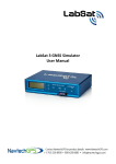
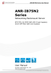
1.4.1. Dimensions
190
205.7
(Unit: mm)
337.2
www.acrosser.com
49.2
35
290
6
9
AIV-HM76V1FL Series User Manual
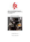
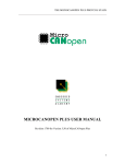
1.4.2. I/O Panel
Front IO
Power Input
COM
COMBO
Remote
HDMI
USB3.0
LAN
Rear I/O
WiFi
3G
GPS
Bluetooth
Fuse
GPIO
10
Acrosser Technology Co., Ltd.
AIV-HM76V1FL Series User Manual
Status/HDD/Power LED Display
LED
Light
Display
G
Green
Status
G
Green
HDD
Y
Yellow
Power LED
Status LED Flashing Status:
A Status LED is used to indicate the status of the system. In normal condition, the
LED will flash a number of blink to state the status. Each blink remains 200 ms ON
followed by a 200 ms OFF. Each Cycle will have a 2-second OFF in between.
LED Flashing
Numbers
Status
0 (Constant On)
Power output runs normally.
1
Standby Mode (System off)
3
Power On Delay
5
Boot Up Delay
6
Soft Off Delay
4
Shutdown Delay
2
Hard Off Delay
If abnormal condition occur, the LED will flash a 1.5-second pulse followed by
numbers of 200 ms pulse to indicate the error status.
LED Flashing
Numbers
Error Status
1 Long, 1 Short
System cannot be turned on or was turned off because
battery voltage is below the Battery Low Voltage.
1 Long, 2 Short
System on/off fail. When motherboard cannot turn on or turn
off after retry.
www.acrosser.com
11
AIV-HM76V1FL Series User Manual
HDMI1, HDMI2
Pin #
Signal
Pin #
Signal
1
DATA2+
2
GND
3
DATA2-
4
DATA1+
5
GND
6
DATA1-
7
DATA0+
8
GND
9
DATA0-
10
CLK+
11
GND
12
CLK-
13
NC
14
NC
15
DDCCL
16
DDCDA
17
GND
18
+5V
19
HPD
USB1, USB2, USB3
Pin #
Signal
Pin #
Signal
1
5V
5
SS_RX -
2
Data -
6
SS_RX +
3
Data +
7
GND
4
GND
8
SS_TX -
9
SS_TX +
LAN1, LAN2
LED
LED1
LED2
12
Light
Status
Off
10Mbps
Green
100Mbps
Orange
1000Mbps
Yellow
Link/Active
Off
LAN Off
Acrosser Technology Co., Ltd.
AIV-HM76V1FL Series User Manual
COMBO
COMBO Connector
Pin #
Signal
Pin #
Signal
1
USB+
11
DDCCL
2
USB-
12
VCC12
3
GND
13
GND
4
VCC5
14
Audio_R
5
GND
15
GND
6
Red
16
MIC_B
7
Green
17
Audio_L
8
Blue
18
MIC_T
9
HSYNC
19
NC
10
VSYNC
20
DDCDA
COMBO Cable
USB2.0 A-Type
Female
D-SUB 40215
Female
SCSI 20pin
Male
Ground
DC Power 2.5
Male
Positive
Audio-L
3.5 Stereo Audio-R
Female
Ground
www.acrosser.com
Audio-R
13
AIV-HM76V1FL Series User Manual
COM1, COM2, COM3, COM4
COM1~3
Pin #
COM4
Signal
Pin #
Signal
1
DCD
1
TX4+
2
SIN
2
TX4-
3
SOUT
3
NC
4
DTR
4
NC
5
GND
5
GND
6
DSR
6
NC
7
RTS
7
NC
8
CTS
8
RX4-
9
RI
9
RX4+
GPIO
Pin # Definition
Wire Color
1
GPO0
Brown
2
GPO1
Orange
3
GPO2
Green
4
GPO3
Blue
5
GND
Black
6
GND
Glay
7
CAN_H
Red/White
8
CAN_L
White
9
GND
Red
10
i-Button
Purple
11
GPI4
Light
Green
12
GPI5
Light Blue
13
GPI6
Pink
14
GPI7
Brown/
White
15
VCC12A
Yellow
GPIO DB15 Cable
14
Wire Color Pin # Definition
Acrosser Technology Co., Ltd.
AIV-HM76V1FL Series User Manual
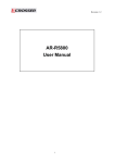
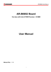
1.4.3. Mainboard
Top View
16
SATA_PWR1
2
GPIO1
1
PIC2
6
1
SATA1
2
3
5
GPS1
PIC1
1
PWR1
1
15
4
2
7
BT1
10
9
JP1
1
1
3
2
1
1
5
8
1
4
CCMOS1
1
CPIC1
10
10
9
10
9
COM3
HDMI1
HDMI2
USB1
USB2
2
1
2
1
2
1
1
COM4
2
COM1
REMOTE1
LED1
10
9
9
COM2
LAN1
USB3
3
2
1
18
2
19
4
19
8
A2
5
18
1
2
A1
7
LAN2
1
A2
B1
B2
8
A1
7
COMBO1
1
B1
B2
9
19
A3
C3
10
1
20
1
2
11
12
Bottom View
1
15
16
17
18
51
52
1
2
MINIPCIE2
2
1
4
15
SW2
5
18
MINIPCIE1
51
SW3
5
74
204
203
204
2
8
4
16
17
1
72
1
1
71 73
203
8
52
SIM1
CF1
www.acrosser.com
15
AIV-HM76V1FL Series User Manual
1.4.4. Power Board
Top View
LED1
CN_12V1
CN_12V2
16
Acrosser Technology Co., Ltd.
AIV-HM76V1FL Series User Manual
2.
Components Assembly
2.1.
2.5” SATA SSD Installation
Step 1:
Loosen the two disk-tray screws by fingers.
Step 2:
Pull out the disk-tray and install your 2.5” SATA disk.
Step 3:
Fasten the disk with 4 screws provided in the package.
Step 4:
Firmly push the disk-tray back into the disk compartment. The disk is now
connected with the system.
Step 5:
Push in the disk-tray and fasten the two disk-tray screws by your screw
driver or fingers.
Step 6:
www.acrosser.com
Complete.
17
AIV-HM76V1FL Series User Manual
2.2.
18
CF Card Installation
Step 1:
Loosen the two card-tray screws by your screw driver.
Step 2:
Pull out the card-tray. Loosen the two screws that locks the card holder.
Slide your CF card into the card holder. Screw back the card holder.
Step 3:
If there is no need to install the SIM card, push in the card-tray and fasten
the two card-tray screws by your screw driver.
Step 4:
Complete.
Acrosser Technology Co., Ltd.
AIV-HM76V1FL Series User Manual
2.3.
SIM Card Installation
Before completing the CF card installtion, you may want to install the SIM card
accroding to your system configuration.
Note:
Step 1:
Leave the CF card-tray on table.
Step 2:
Use a clip to install your SIM card into the SIM1 slot on the mainboard.
Pay attention to its orientation, and do not scratch the contacts.
Step 3:
Push in the card-tray and fasten the two card-tray screws by your screw
driver.
Step 4:
Complete.
To remove the card, first you have to push it in, and then pull it out.
www.acrosser.com
19
AIV-HM76V1FL Series User Manual
2.4.
20
DIMM Card Installation
Step 1:
Use your screw driver to remove the DIMM card cover plate located at the
chassis bottom.
Step 2:
Install your DIMM card into the CN_DIMM1 or CN_DIMM2 slot on
the mainboard. Pay attention to its orientation, and do not scratch the
contacts.
Step 3:
Place back the DIMM card cover plate and have it fastened.
Step 4:
Complete.
Acrosser Technology Co., Ltd.
AIV-HM76V1FL Series User Manual
2.5.
3.5G / WiFi Module Installation
MINIPCIE2
(WiFi)
MINIPCIE1
(3.5G)
Step 1:
Use your screw driver to remove the cover plate located at the chassis
bottom.
Step 2:
For 3.5G module, install to the MINIPCIE1 slot on the mainboard.
For WiFi module, install to the MINIPCIE2 slot on the mainboard.
Pay attention to its orientation, and do not scratch the contacts.
Step 3:
Attch the RF plug from the system to your module.
Step 4:
Place back the cover plate and have it fastened.
Step 5:
Complete.
www.acrosser.com
21
AIV-HM76V1FL Series User Manual
2.6.
Antenna Connection
Connect your antenna needed according to your system configuration.
2.7.
Power Connection
Connect your power cable.
9V ~ 32V DC input connector
Terminal Block: 3 pin
Pitch: 5.08mm
22
Pin #
Signal
V+
9V ~ 32V DC Power Input
IGN
Ignition On (Hi Active)
V-
GND
Acrosser Technology Co., Ltd.
AIV-HM76V1FL Series User Manual
2.8.
Blade-type Fuse Holder
Power-input fuse suggestion:
Output: 12V/100W (Input: 9V~32V/111W, Efficiency: 90%)
Note:
Car Battery
Blade-type fuse suggestion
Remarks
12V System
CONQUER ATQ-10
Voltage Rating: 32V;
Current Rating: 10A
24V System
CONQUER ATQ-5
Voltage Rating: 32V;
Current Rating: 5A
You may have to use a needle-nose pliers to grip on the fuse and pull it out.
www.acrosser.com
23
AIV-HM76V1FL Series User Manual
3.
BIOS Settings
This chapter describes the BIOS menu displays and explains how to perform
common tasks needed to get the system up and running. It also gives detailed
explanation of the elements found in each of the BIOS menus. The following topics
are covered:
• Main Setup
• Advanced Setup
• Chipset Setup
• Boot Setup
• Security Setup
• Save & Exit Setup
Once you enter the Award BIOS™ CMOS Setup Utility, the Main Menu will appear
on the screen. Use the arrow keys to highlight the item and then use the <Pg Up>
<Pg Dn> keys to select the value you want in each item.
3.1.
Main Setup
The BIOS setup main menu includes some options. Use the [Up/Down] arrow key to
highlight the option, and then press the [Enter] key to select the item and configure
the functions.
Main
Aptio Setup Utility - Copyright (C) 2012 American Megatrends, Inc.
Advanced Chipset Boot Security Save & Exit
BIOS Information
BIOS Vendor
Core Version
Compliancy
Project Version
Build Date and Time
American Megatrends
4.6.5.3
UEFI 2.3; PI 1.2
AMB-HM76V1FL V1.0
03/13/2015 11:22:33
PCH Information
Intel PCH SKU Name
HM76
Processor Information
Intel(R) Celeron(R) CPU 1047UE @ 1.40GHz
Name
IvyBridge
1400 MHz
Frequency
306a9
Processor ID
Stepping
E1
2Core(s) / 2Thread(s)
Number of Processors
19
Microcode Revision
GT Info
GT2 (900 MHz)
IGFX VBIOS Version
Memory RC Version
Total Memory
Memory Frequency
2143
1.5.0.0
4096 MB (DDR3)
1600 MHz
Choose the system default
language
→←: Select Screen
↑↓: Select Item
Enter: Select
+/-: Change Opt.
F1: General Help
F2: Previous Values
F3: Optimized Defaults
F4: Save & Exit
ESC: Exit
Version 2.15.1226. Copyright (C) 2012 American Megatrends, Inc.
24
Acrosser Technology Co., Ltd.
AIV-HM76V1FL Series User Manual
Main
Aptio Setup Utility - Copyright (C) 2012 American Megatrends, Inc.
Advanced Chipset Boot Security Save & Exit
Processor Information
Intel(R) Celeron(R) CPU 1047UE @ 1.40GHz
IvyBridge
Name
1400 MHz
Frequency
Processor ID
306a9
E1
Stepping
2Core(s) / 2Thread(s)
Number of Processors
19
Microcode Revision
GT2 (900 MHz)
GT Info
IGFX VBIOS Version
Memory RC Version
Total Memory
Memory Frequency
2143
1.5.0.0
4096 MB (DDR3)
1600 MHz
ME FW Version
ME Firmware SKU
8.0.10.1464
1.5MB
System Language
[English]
System Date
System Time
[Fri 05/23/2014]
[11:22:33]
Access Level
Administrator
Set the Time. Use Tab
to switch between Time
elements.
→←: Select Screen
↑↓: Select Item
Enter: Select
+/-: Change Opt.
F1: General Help
F2: Previous Values
F3: Optimized Defaults
F4: Save & Exit
ESC: Exit
Version 2.15.1226. Copyright (C) 2012 American Megatrends, Inc.
Note:
Listed at the bottom of the menu are the control keys. If you need any help with the
item fields, you can press <F1> key, and it will display the relevant information.
• System Language
Choose the system default language.
• System Date
Set the system date. Note that the ‘Day’ automatically changes when you set the
date.
• System Time
Set the system time.
www.acrosser.com
25
AIV-HM76V1FL Series User Manual
3.2.
Advanced Setup
Main
Aptio Setup Utility - Copyright (C) 2012 American Megatrends, Inc.
Advanced Chipset Boot Security Save & Exit
SATA Configuration
USB Device
F81216 Second Super IO Configuration
W83627DHG HW Monitor
Power Sub System
SATA Device Options
Settings
→←: Select Screen
↑↓: Select Item
Enter: Select
+/-: Change Opt.
F1: General Help
F2: Previous Values
F3: Optimized Defaults
F4: Save & Exit
ESC: Exit
Version 2.15.1226. Copyright (C) 2012 American Megatrends, Inc.
3.2.1. SATA Configuration
SATA device options settings.
Aptio Setup Utility - Copyright (C) 2012 American Megatrends, Inc.
Advanced
SATA Controller(s)
SATA Mode Selection
[Enabled]
[AHCI]
Serial ATA Port 1
Software Preserve
Port 0
CF CARD
Software Preserve
Port 4
Empty
Unknown
[Enabled]
Empty
Unknown
[Enabled]
Enable or disable SATA
Device.
→←: Select Screen
↑↓: Select Item
Enter: Select
+/-: Change Opt.
F1: General Help
F2: Previous Values
F3: Optimized Defaults
F4: Save & Exit
ESC: Exit
Version 2.15.1226. Copyright (C) 2012 American Megatrends, Inc.
26
Acrosser Technology Co., Ltd.
AIV-HM76V1FL Series User Manual
• SATA Controller(s)
Options
Enabled / Disabled
Description
Enable or disable SATA device.
• SATA Mode Selection
Options
IDE / AHCI
Description
Determines how SATA controller(s) operate.
3.2.2. USB Device
USB configuration parameters.
Aptio Setup Utility - Copyright (C) 2012 American Megatrends, Inc.
Advanced
USB Device
USB Devices:
1 Keyboard, 1 Mouse, 2 Hubs
Legacy USB Support
[Enabled]
Enable Legacy USB
support. AUTO option
disables legacy support
if no USB devices are
connected. DISABLE option
will keep USB devices
available only for EFI
applicatipon.
→←: Select Screen
↑↓: Select Item
Enter: Select
+/-: Change Opt.
F1: General Help
F2: Previous Values
F3: Optimized Defaults
F4: Save & Exit
ESC: Exit
Version 2.15.1226. Copyright (C) 2012 American Megatrends, Inc.
• Legacy USB Support
Options
Enabled
Disabled
Auto
www.acrosser.com
Description
Enables Legacy USB support.
Keep USB devices available only for EFI applications.
Disables legacy support if no USB devices are connected.
27
AIV-HM76V1FL Series User Manual
3.2.3. F81216 Second Super IO Configuration
System second super IO chip parameters.
Aptio Setup Utility - Copyright (C) 2012 American Megatrends, Inc.
Advanced
F81216 Second Super IO Configuration
F81216 Second Super IO Chip
COM 1 Configuration
COM 2 Configuration
COM 3 Configuration
COM 4 Configuration
F81216 SecondIO
COM4 422/485 function
[RS-422]
Set Parameters of COM 1
→←: Select Screen
↑↓: Select Item
Enter: Select
+/-: Change Opt.
F1: General Help
F2: Previous Values
F3: Optimized Defaults
F4: Save & Exit
ESC: Exit
Version 2.15.1226. Copyright (C) 2012 American Megatrends, Inc.
• COM 1 ~ COM 4 Configuration
This option sets the parameters of COM1 ~ COM4.
• COM4 422/485 function
This option sets the COM4 function to RS-422 or RS-485.
28
Acrosser Technology Co., Ltd.
AIV-HM76V1FL Series User Manual
3.2.4. W83627DHG HW Monitor
Monitor hardware status.
Aptio Setup Utility - Copyright (C) 2012 American Megatrends, Inc.
Advanced
F8121PC Health Status
SYSTIN temperature
CPUTIN temperature
VCORE
5V
12V
3.3V
VBAT
:
:
:
:
:
:
:
+41°C
+51°C
+0.840 V
+5.150 V
+11.880 V
+3.440 V
+3.280 V
→←: Select Screen
↑↓: Select Item
Enter: Select
+/-: Change Opt.
F1: General Help
F2: Previous Values
F3: Optimized Defaults
F4: Save & Exit
ESC: Exit
Version 2.15.1226. Copyright (C) 2012 American Megatrends, Inc.
• SYSTIN temperature
This item displays the system temperature.
• CPUTIN temperature
This item displays the CPU temperature.
• 5V
This item displays the 5V voltage level.
• 12V
This item displays the 12V voltage level.
• 3.3V
This item displays the 3.3V voltage level.
• VBAT
This item displays the battery voltage level.
www.acrosser.com
29
AIV-HM76V1FL Series User Manual
3.2.5. Power Sub System
Power Sub System.
Aptio Setup Utility - Copyright (C) 2012 American Megatrends, Inc.
Advanced
Model
Firmware Version
HM76V1
V1.0
Power Board Type
[In-Vehicle]
Battery Voltage
11.62 V
Battery Low Monitor
Battery Low Delta
Remote Switch
Power On Delay (Sec.)
Soft-Off Delay (Sec.)
Shutdown Delay (Sec.)
Hard-Off Delay (Sec.)
[Disabled]
[1.5 V]
[Disabled]
8
5
180
60
[Enabled]/[Disabled]
Battery Low Voltage
Monitor Function
→←: Select Screen
↑↓: Select Item
Enter: Select
+/-: Change Opt.
F1: General Help
F2: Previous Values
F3: Optimized Defaults
F4: Save & Exit
ESC: Exit
Version 2.15.1226. Copyright (C) 2012 American Megatrends, Inc.
• Power Board Type
Options
In-Vehicle / Embedded
Description
Displays the power board type.
• Battery Voltage
Detects and display the battery voltage level.
Note:
The following items apper only if the “Power Board Type” is [In-Vehicle].
• Battery Low Monitor
Options
Enabled / Disabled
• Battery Low Delta
Options
0.5 / 1.0 / 1.5 / 2.0 / 2.5 / 3.0
• Remote Switch
Options
Enabled / Disabled
30
Description
Enables or disables the monitor function of low battery voltage.
Description
Sets the battery delta level. Once the battery voltage drops below
this level, the battery will be detected as battery low.
Description
Enables or disables the function of remote switch.
Acrosser Technology Co., Ltd.
AIV-HM76V1FL Series User Manual
3.3.
• Power On Delay (Sec.)
Options
2 ~ 60
Description
The delay between power on and system work.
• Soft-Off Delay (Sec.)
Options
0 ~ 3600
Description
The delay before system shutdown.
• Shutdown Delay (Sec.)
Options
120 ~ 3600
Description
The delay between system shutdown and system off.
• Hard-Off Delay (Sec.)
Options
0 ~ 3600
Description
The delay before all power off.
Chipset Setup
Main
Aptio Setup Utility - Copyright (C) 2012 American Megatrends, Inc.
Advanced Chipset Boot Security Save & Exit
Lan 1
LAN 1 ASPM
[Enabled]
[Disabled]
Lan 2
LAN 2 ASPM
[Enabled]
[Disabled]
Audio
[Auto]
Control the Lan Port
Enable / Disable.
SB USB Configuration
Graphics Configuration
→←: Select Screen
↑↓: Select Item
Enter: Select
+/-: Change Opt.
F1: General Help
F2: Previous Values
F3: Optimized Defaults
F4: Save & Exit
ESC: Exit
Version 2.15.1226. Copyright (C) 2012 American Megatrends, Inc.
• Lan 1, Lan 2
Options
Disabled / Enabled
www.acrosser.com
Description
Control the LAN Port Enable / Disable.
31
AIV-HM76V1FL Series User Manual
• LAN 1 ASPM, LAN 2 ASPM
Options
Description
L0s, L1, L0sL1, Auto, Disabled Sets the ASPM (Active State Power Management Settings) level
for LAN1 and LAN2.
• Audio
Control detection of the Azalia device.
Options
Disabled
Auto
Description
Azalia will be unconditionally disabled.
Azalia will be enabled if present, disabled otherwise.
3.3.1. SB USB Configuration
Aptio Setup Utility - Copyright (C) 2012 American Megatrends, Inc.
Chipset
SB USB Configuration
xHCI Mode
[Auto]
EHCI1
[Enabled]
EHCI2
[Enabled]
Mode of operation of xHCI
controller.
→←: Select Screen
↑↓: Select Item
Enter: Select
+/-: Change Opt.
F1: General Help
F2: Previous Values
F3: Optimized Defaults
F4: Save & Exit
ESC: Exit
Version 2.15.1226. Copyright (C) 2012 American Megatrends, Inc.
• xHCI Mode
Options
Disabled / Auto / Smart Auto
• EHCI1, EHCI2
Options
Enabled / Disabled
32
Description
Select the operation mode of xHCI controller.
Description
Control the USB EHCI functions. One EHCI controller must always
be enabled.
Acrosser Technology Co., Ltd.
AIV-HM76V1FL Series User Manual
3.3.2. Graphics Configuration
Aptio Setup Utility - Copyright (C) 2012 American Megatrends, Inc.
Chipset
System Agent Bridege Name
System Agent RC Version
VT-d Capability
IvyBridge
1.5.0.0
Unsupported
DVMT Pre-Allocated
DVMT Total Gfx Mem
[64M]
[256M]
Primary IGFX Boot Display
[VBIOS Default]
Select DVMT 5.0
Pre-Allocated (Fixed)
Graphics Memory size
used by the Internal
Graphics Device.
→←: Select Screen
↑↓: Select Item
Enter: Select
+/-: Change Opt.
F1: General Help
F2: Previous Values
F3: Optimized Defaults
F4: Save & Exit
ESC: Exit
Version 2.15.1226. Copyright (C) 2012 American Megatrends, Inc.
• DVMT Pre-Allocated
Options
Description
32M / 64M / 96M / 128M / 160M Select DVMT 5.0 Pre-Allocated (Fixed) Graphics Memory size
/ 192M / 224M / 256M / 288M / used by the Internal Graphics Device.
320M / 352M / 384M / 416M /
448M / 480M / 512M / 1024M
• DVMT Total Gfx Mem
Options
128M / 256M / MAX
Description
Select DVMT 5.0 Total Graphics Memory size used by the Internal
Graphics Device.
• Primary IGFX Boot Display
Options
Description
VBIOS Default / D_SUB /
Select which video device will be activated during POST. This
HDMI 1 / HDMI 2
has no effect if external graphics present. Secondary boot display
selection will appear based on your selection.
The VGA modes will be supported only on primary display.
www.acrosser.com
33
AIV-HM76V1FL Series User Manual
3.4.
Boot Setup
Main
Aptio Setup Utility - Copyright (C) 2012 American Megatrends, Inc.
Advanced Chipset Boot Security Save & Exit
Boot Configuration
Setup Prompt Timeout
Bootup Numlock State
2
[On]
Boot Logo
[Enabled]
CSM16 Module Version
07.69
Number of seconds to wait
for setup activation key.
65535(0xFFFF) means
indefinite waiting.
Driver Option Priorities
Boot Option Priorities
→←: Select Screen
↑↓: Select Item
Enter: Select
+/-: Change Opt.
F1: General Help
F2: Previous Values
F3: Optimized Defaults
F4: Save & Exit
ESC: Exit
Version 2.15.1226. Copyright (C) 2012 American Megatrends, Inc.
• Setup Prompt Timeout
Options
N/A
Description
The number of seconds to wait for setup activation key.
65535(0xFFFF) means indefinite waiting.
• Bootup NumLock State
Options
On / Off
Description
Select the keyboard NumLock state.
• Boot Logo
Options
Enabled / Disabled
Description
Enables or disables Quiet Boot option.
• CSM16 Module Version
This item shows the information of the CSM16 Module Version.
• Driver Option Priorities
This item enables adding, deleting, or selecting the drive options to be shown in the
setup sequence.
• Boot Option Priorities
Set the system boot order.
34
Acrosser Technology Co., Ltd.
AIV-HM76V1FL Series User Manual
3.5.
Security Setup
Main
Aptio Setup Utility - Copyright (C) 2012 American Megatrends, Inc.
Advanced Chipset Boot Security Save & Exit
Password Description
If ONLY the Administrator’s password is set,
then this only limits access to Setup and is
only asked for when entering Setup.
If ONLY the User’s password is set, then this
is a power on password and must be entered to
boot or enter Setup. In Setup the User will
have Administrator rights.
The password length must be
in the following range:
Minimum length
3
Maximum length
20
Administrator Password
System Mode state
Secure Boot state
Setup
Disabled
Set Administrator
Password
→←: Select Screen
↑↓: Select Item
Enter: Select
+/-: Change Opt.
F1: General Help
F2: Previous Values
F3: Optimized Defaults
F4: Save & Exit
ESC: Exit
Version 2.15.1226. Copyright (C) 2012 American Megatrends, Inc.
• Administrator Password
Set Administrator Password
• System Mode state
This item shows whether the password has been set or not.
• Secure Boot state
Decide whether a password is needed before boot up.
www.acrosser.com
35
AIV-HM76V1FL Series User Manual
3.6.
Save & Exit Setup
Main
Aptio Setup Utility - Copyright (C) 2012 American Megatrends, Inc.
Advanced Chipset Boot Security Save & Exit
Save Changes and Exit
Discard Changes and Exit
Exit system setup after
saving the changes.
Save Options
Save Changes
Discard Changes
Restore Defaults
Save as User Defaults
Restore User Defaults
Boot Override
→←: Select Screen
↑↓: Select Item
Enter: Select
+/-: Change Opt.
F1: General Help
F2: Previous Values
F3: Optimized Defaults
F4: Save & Exit
ESC: Exit
Version 2.15.1226. Copyright (C) 2012 American Megatrends, Inc.
• Save Changes and Exit
Exit system setup after saving the changes.
• Discard Changes and Exit
Exit system setup without saving any changes.
• Save Options
Save the options that have been made so far.
• Save Changes
Save Changes done so far to any of the setup options.
• Discard Changes
Discard Changes done so far to any of the setup options.
• Restore Defaults
Restore/Load Default values for all the setup options.
• Save as User Defaults
Save the changes done so far as User Defaults.
• Restore User Defaults
Restore the User Defaults to all the setup options.
• Boot Override
Select the boot device.
36
Acrosser Technology Co., Ltd.
AIV-HM76V1FL Series User Manual
4.
Driver and Utility Installation
4.1.
Driver CD Interface Introduction
Acrosser provides a Driver CD compiled with all the drivers, utilities, applications and
documents this product may need.
Put the Driver CD into your CD-ROM drive. The Driver CD will automatically detect
the mainboard information to see if they are matched. The following error messages
appear if you use an incorrect Driver CD version with your mainboard. Please find
the correct Driver CD to proceed.
www.acrosser.com
37
AIV-HM76V1FL Series User Manual
Put the correct Driver CD of your mainboard into your CD-ROM drive. The following
installation screen should appear.
If not, enter the root folder of the Driver CD, run the excution file “Setup.exe“.
38
Acrosser Technology Co., Ltd.
AIV-HM76V1FL Series User Manual
4.2.
Driver Installation Page
Step 1:
Select the “Driver” tab. Click the “Select All” button to select all the driver
checkboxes, and then click “Install” button to start installing all the selected drivers.
Step 2:
The driver installation completeed. The configuration will be valid after reboot.
www.acrosser.com
39
AIV-HM76V1FL Series User Manual
Note:
Select the “Clear All“ button will clear all the selections, and then you can select the
driver you want to install one by one, but the “Chipset” driver has to be installed
before installing all the others.
4.3.
Utility Installation Page
Before launching the utility, you should install ”Driver” to initiate peripherals, e.g.
GPIO and WatchDog.
This “Test Utility” can be used to verify both system GPIO and WatchDog features.
Note:
To run the Testing Utility completely, you should do it at test-signed kernel-mode
under Windows 7 x64 by the command “BCDEdit /set testsigning on”.
For more information, please refer to MSDN by the following URL http://msdn.
microsoft.com/en-us/library/windows/hardware/ff542202(v=vs.85).aspx
Step 1:
Select the “Utility” tab. Click the “Test Utility” box.
40
Acrosser Technology Co., Ltd.
AIV-HM76V1FL Series User Manual
Step 2:
The “Test Utility” screen appears.
Select (1) GPIO Utility:
Select (2) WatchDog Utility:
www.acrosser.com
41
AIV-HM76V1FL Series User Manual
Select (3) Power Subsystem:
Select (4) Can Bus:
Select (5) I-Button:
42
Acrosser Technology Co., Ltd.
AIV-HM76V1FL Series User Manual
4.4.
Application Installation Page
Step 1:
Select the “Application” tab. Click the “Acrobat Reader” box.
Step 2:
Please install “Acrobat Reader”. This application is needed for reading the User
Manual in PDF format.
www.acrosser.com
43
AIV-HM76V1FL Series User Manual
Step 3:
Please install “Intel_MEI” and “Acrosser Driver” into the system. Windows OS will
create “AcroDev” device.
Step 4:
If the “Windows Security” warning message appears, select “Install this driver
software anyway” to go on next step.
44
Acrosser Technology Co., Ltd.
AIV-HM76V1FL Series User Manual
Step 5:
Install “Drivers for Optional Modules”.
www.acrosser.com
45
AIV-HM76V1FL Series User Manual
4.5.
Document Page
The user manual is stored in the “Document” folder.
Note:
46
To read the PDF file, you will have to install “Acrobat Reader” first. Please refer to
the “Application Installation Page”.
Acrosser Technology Co., Ltd.
AIV-HM76V1FL Series User Manual
5.
Software Installation and
Programming Guide
5.1.
Introduction
5.1.1. CAN Bus
5.1.1.1. Overview
The CAN bus APIs provide interfaces to CAN bus subsystem. By invoking these
APIs, programmers can implement the applications which have the functions listed
below:
1. Set the BAUD rate.
2. Send the CAN packages over the CAN bus.
3. Receive the CAN packages via the CAN bus hardware interface.
4. Set the CAN package filter to selectively receive CAN packages with specific ID.
5. Set the mask bits to selectively make some filter bits take effect.
In the folder ‘HM76V1FL\Utility’ on the CD, we provide:
1. API header file.
2. API library in static library format and shared library format.
3. Test utility.
5.1.1.2. CAN Message Format
// TYPE DEFINITION
typedef
typedef
typedef
typedef
typedef
typedef
char
unsigned char
short
unsigned short
unsigned long
int
i8;
u8;
i16;
u16;
u32;
i32;
struct CanMsg {
u32 id;
u8 id_type;
u8 length;
u8 data[8];
}
www.acrosser.com
47
AIV-HM76V1FL Series User Manual
To transmit a CAN packet, the programmer has to fill in the fields in the variable of
type CanMsg and pass this CanMsg variable as an argument to invoke the APIs.
The fields in CAN message are described below:
id:
This field holds the ID information of the CAN packet. In a ‘Standard Data Frame’
CAN packet, the ID field consists of 11 bits of binary digitals. In an ‘Extended Data
Frame’ CAN packet, the ID field consists of 29 bits of binary digitals. That the CAN
packet is a ‘Standard Data Frame’ packet or an ‘Extended Data Frame’ packet is
determined by the ‘id_type’ field in the CanMsg variable.
The ‘id’ field in the CanMsg variable is a 32-bit long space. If a CanMsg variable is
configured as a ‘Standard Data Frame’ CAN packet, the bit[0] ~ bit[10] in the ‘id’ field
is the ID of the CAN packet. The bit[11] ~ bit[31] are ignored when the APIs in the
library processing the CanMsg variable.
If a CanMsg variable is configured as an ‘Extended Data Frame’ CAN packet, the
bit[0] ~ bit[28] in the ‘id’ field is the ID of the CAN packet. The bit[29] ~ bit[31] are
ignored when the APIs in the library processing the CanMsg variable.
id_type:
This field identifies that the CAN packet is a ‘Standard Data Frame’ CAN packet or a
‘Extended Data Frame’ CAN packet:
struct CanMsg canMsg;
canMsg.id_type = EXT_ID; // A ‘Extended Data Frame’ packet
canMsg.id_type = STD_ID; // A ‘Standard Data Frame’ packet
length:
This field identifies the number of data bytes in the next field ‘data[8]’ which are filled
with effective data. Because the ‘data’ field is an 8-byte long array, the range of this
field ‘length’ is 0 ~ 8.
data[8]:
This array of data will be filled with effective data.
For example:
struct CanMsg msg;
msg.data[0] = 0xa1;
msg.data[1] = 0xb2;
48
Acrosser Technology Co., Ltd.
AIV-HM76V1FL Series User Manual
msg.data[2] = 0xc3;
msg.length = 3;
5.1.2. GPIO and Watchdog
5.1.2.1. Overview
This model provides both a GPIO interface and a Watchdog timer. Users can use
the GPIO and Watchdog APIs to configure and to access the GPIO interface and the
Watchdog timer. The GPIO has four input pins and four output pins. The Watchdog
timer can be set to 1~255 seconds. Setting the timer to zero disables the timer. The
remaining seconds of the timer to reboot can be read from the timer.
5.1.2.2. Installing Device Driver
Before executing the applications which invoke the GPIO or Watchdog APIs, users
should make sure that the Linux device driver or the Windows device driver has
been installed.
On Linux platform, after successfully installing the device driver, a character device
node named “/dev/AcroDev” will be created automatically. The APIs open the device
node “/dev/AcroDev” implicitly so acquiring a file descriptor of “/dev/AcroDev” is not
ncecssary.
On Windows platform, after successfully installing the device driver, there is a device
which shows ‘Acrosser Device’ in the ‘Device Manager’. The APIs on Windows
platform open this device implicitly.
5.1.3. Power Subsystem
5.1.3.1. Overview
The Power Subsystem APIs can be used to get and set the configuration of power
subsystem. By invoking the Power Subsystem APIs, users can:
1.
2.
3.
4.
5.
6.
Get the firmware version number of the Power Subsystem.
Set all the settings of the Power Subsystem to the default values.
Get/Set the status of the remote switch(ENABLE or DISABLE).
Get the battery voltage.
Get/set the status of the battery monitor (ON or OFF).
Get/set the delta value which identifies how much the battery voltage can be
lower than the nominal voltage. When the voltage is lower than the tolerable
voltage, the power subsystem turns off the system.
7. Get/set the Soft Off deley.
8. Get/set the Hard Off delay.
9. Get/set the Power On delay.
10.Get/set the Shutdown delay.
www.acrosser.com
49
AIV-HM76V1FL Series User Manual
The power subsystem connects to the main system via the COM port. On the
Linux platform, the actual port number to which the Power Subsystem connects
is determined by the Linux. The default supported COM interfaces on Linux are
COM1~COM4. Users must take extra steps to configure Linux kernel in order to
support COM ports which do not fall into the range COM1 ~ COM4. Please refer to
Appendix A for more information. Users don’t need extraordinary setup on Windows
platform to support COM ports.
5.1.4. I-Button Function
In the API library, we provide a set of I-Button functions. Users can use the functions
to:
1. Reset the I-Button.
2. Read data from the I-Button.
3. Write data to the I-Button.
5.2.
API List and Descriptions
5.2.1. CAN Bus
Syntax:
i32 getCanFwVer(PicInfo *ver)
Description:
This function gets the version information of the CAN Bus
firmware.
Parameters:
The definition of struct ‘PicInfo’ is:
struct PicInfo {
u8 info[12];
}
This API returns the version information and store the
information in the memory which is pointed at by the
pointer ‘ver’.
Return Value:
50
If this function gets the version information successfully, it
returns 0, any other returned value stands for error.
Acrosser Technology Co., Ltd.
AIV-HM76V1FL Series User Manual
Syntax:
i32 getCanBaudRate(u8 *baud)
Description:
This function gets the current setting of the Baud Rate
of the CAN Bus. This function gets an ‘unsigned char’ to
represent the Baud Rate. Here is the table for the Baud
Rate:
Unsigned Char
1
2
3
4
5
6
7
8
9
Baud Rate
10K
20K
50K
100K
125K
250K
500K
800K
1000K
Users can use the macros listed below to set the Baud
Rate:
/* Baud Rate */
#define BAUD_RATE_10K
1
#define BAUD_RATE_20K
2
#define BAUD_RATE_50K
3
#define BAUD_RATE_100K
4
#define BAUD_RATE_125K
5
#define BAUD_RATE_250K
6
#define BAUD_RATE_500K
7
#define BAUD_RATE_800K
8
#define BAUD_RATE_1000K 9
Parameters:
This function gets a number which represents the specific
Baud Rate and stores it at the memory which is pointed at
by the pointer ‘baud’.
Return Value:
If this function gets the baud rate successfully, it returns 0,
any other returned value stands for error.
Syntax:
i32 setCanBaudRate(u8 baud)
Description:
This function sets the Baud Rate of the CAN Bus.
Parameters:
It takes an ‘unsigned char’ as the parameter and sets the
Baud Rate according to the value stored at the parameter
‘baud’. The correspondence between the Baud rate and
the value to set to the function is the same as the table
listed in the previous API ‘getCanBaudRate( )’
Return Value:
If this function sets the baud rate successfully, it returns 0,
any other returned value stands for error.
www.acrosser.com
51
AIV-HM76V1FL Series User Manual
Syntax:
i32 sendCanMessage(struct CanMsg *buffer, u8 count)
Description:
This function sends out CAN packages over the CAN bus.
Parameters:
If there is more than one CAN packet to send, these CAN
packages are stored in an array of type ‘CanMsg’. This
function sends out packets in a sequential fashion. The
memory address of the first CAN packet to be sent is
pointed at by the parameter ‘buffer’. The number of CAN
packets to be sent is indicated by the parameter ‘count’.
Return Value:
If this function sends the CAN packet successfully, it
returns 0, any other returned value stands for error.
Here is an example:
If the CAN packets in the array ‘canAry[]’ have been
initialized. The code listed below will send out the CAN
packets in the ‘canAry[]’ over the CAN bus.
unsigned int result = 0;
struct CanMsg canAry[30];
/* …
Initialize the CAN packages in the canAry[30]
*/
result = sendCanMessages( canAry, 30 );
if( result != 0)
fprintf( stderr, “Send CAN package error!\n”);
Syntax:
i32 getCanMessage(struct CanMsg *buffer, u8 count)
Description:
This function receives CAN packets from the CAN bus
subsystem.
Parameters:
This function stores received CAN packages sequentially
at an array of type ‘CanMsg’. The number of packages to
receive is indicated by the parameter ‘count’.
Return Value:
If this function receives the CAN packet successfully, it
returns 0, any other returned value stands for error.
Here is an example:
If the array ‘canAry[]’ of type ‘CanMsg’ has been declared
and allocated. The code listed below will receive 30 CAN
packages from the CAN bus subsystem and stores the
packages in the ‘canAry[]’.
unsigned int result = 0;
struct CanMsg canAry[30];
result = getCanMessage( canAry, 30 );
if( result != 0)
fprintf( stderr, “Fail to receive CAN packets!\n”);
52
Acrosser Technology Co., Ltd.
AIV-HM76V1FL Series User Manual
Syntax:
i32 getCanMask(struct CanMask *mask)
Description:
This function gets the current setting of the acceptance
masks. Masks are used to determine which bits in the
ID field of the CAN packet are examined with the filters.
There are two acceptance masks (mask0 and mask1)
and six acceptance filters (filter0 ~ filter5) in the CAN Bus
subsystem. Filter0 ~ filter1 are associated with mask0.
Filter2 ~ filter4 are associated with mask1.
Here is the Mask/Filter truth table:
Mask bit n
Filter bit n
0
1
1
1
1
x
0
0
1
1
Message ID
bit n
x
0
1
0
1
Accept or
reject bit n
Accept
Accept
Reject
Reject
Accept
Note: x = don’t care
Parameters:
This parameter ‘mask’ is a pointer to a variable of type
‘CanMask’. Users use the field ‘maskId’ to indicate the
mask they want and the API put the setting of the mask in
the ‘mask’ field.
struct CanMask {
u8 maskId; // 0 or 1
u32 mask;
}
Return Value:
If this function receives the mask setting successfully, it
returns 0, any other returned value stands for error.
For example:
struct CanMask a_mask;
a_mask.maskId = 0; // indicate the mask0
i32 result;
result = getCanMask(&a_mask); // The setting of the
mask is put at
// a_mask.mask
if( result != 0)
printf(“Fail to get mask!\n”);
www.acrosser.com
53
AIV-HM76V1FL Series User Manual
Syntax:
i32 setCanMask(struct CanMask mask)
Description:
This function sets the bit patterns to the indicated mask.
The target mask is indicated by the ‘maskId’ field in a
CanMask variable.
Parameters:
This functions takes a variable of type ‘CanMask’. User set
the bit patterns they want to the ‘mask’ field in a ‘CanMask’
variable.
struct CanMask {
u8 maskId; // 0 or 1
u32 mask;
}
For example:
struct CanMask varMask;
i32 result;
varMask.maskId = 1;
varMask.mask = 0x12345678;
result = setCanMask(varMask);
Return Value:
If this function sets the mask setting successfully, it returns
0, any other returned value stands for error.
Syntax:
i32 getCanFilter(struct CanFilter *varFilter)
Description:
This function gets the current setting of the acceptance
filter. Use the ‘filterId’ field in a ‘CanFilter’ variable to
indicate the filter you want and the API puts the setting
of the indicated filter in the ‘filter’ field in the CanFilter
variable ‘varFilter’.
Parameters:
This function takes a pointer to a ‘CanFilter’ type variable.
For example:
struct CanFilter varFilter;
i32 result;
result = getCanFilter(&varFilter);
if(result != 0)
printf(“Fail to get the filter!\n”);
Return Value:
54
If this function gets the filter successfully, it returns 0, any
other returned value stands for error.
Acrosser Technology Co., Ltd.
AIV-HM76V1FL Series User Manual
Syntax:
i32 setCanFilter(struct CanFilter *varFilter)
Description:
This function sets the bit pattern to the filter. By indicating
the ‘filterType’ field in the ‘varFilter’ variable, the bit pattern
in the ‘filter’ field will be taken as an ‘Standard ID’ filter or
‘Extended ID’ filter.
struct CanFilter {
u8 filterId; // There are six filters so the filterId = 0 ~ 5
u8 filterType; // filterType = STD_ID or filterType =
EXT_ID
u32 filter;
}
If a filter is configured as a ‘Standard ID’ filter, only bit18
~ bit28 in the mask take effect when filtering the CAN
packet.
Parameters:
This function takes a pointer to a variable of type ‘CanFilter’
as the parameter. Users set up the ‘filterId’. There are six
filters so the ‘filterId’ could be 0 ~ 5. Filter0 and filter1 are
associated with mask0. Filter2 ~ filter5 are associated with
mask1.
By setting up ‘filterType’, users indicate the type of the
filter. Filter type could be ‘STD_ID’ or ‘EXT_ID’.
Depending on the filter type, the ‘filter’ field in the CanFilter
variable could be 0x0 ~ 0x7FF (11 bits) when filter type is
‘STD_ID’. If the filter type is ‘EXT_ID’, the ‘filter’ field in the
CanFilter variable could be 0x0 ~ 0x1FFFFFFF (29 bits).
For example:
struct CanFilter varFilter;
i32 result;
varFilter.filterId = 3;
varFilter.filterType = STD_ID;
varFilter.filter = 0x555;
result = setCanFilter(&varFilter);
if( result != 0)
printf(“Fail to set up the filter!\n”);
Return Value:
www.acrosser.com
If this function sets the filter successfully, it returns 0, any
other returned value stands for error.
55
AIV-HM76V1FL Series User Manual
5.2.2. GPIO and Watchdog
5.2.2.1. GPIO
Syntax:
i32 getChLevel(u8 *val)
Description:
Get the status of GPIO input pins and output pins, and put
the value at *val.
Parameters:
This function takes a pointer to an unsigned char variable
as the parameter.
The bit0 ~ bit3 in the pointed variable ‘*val’ is the status of
the output pins. The bit4 ~ bit7 in the pointed variable ‘*val’
is the status of the input pins.
For example:
u8 val;
i32 result;
result = getChLevel( &val);
if(result != 0)
printf(“Fail to get GPIO status!\n”);
Return Value:
If the function gets the value successfully, it returns 0, any
other returned value stands for error.
Syntax:
i32 setChLevel(u8 val)
Description:
Set the status of GPIO Output pins.
Parameters:
This function takes an unsigned char as the parameter.
The bit0 ~ bit3 in variable ‘val’ represent the status of the
output pins. The bit3 ~ bit7 in the variable ‘val’ are of no
use and can be neglected.
For example:
u8 val = 0xf;
i32 result;
result = setChLevel(val);
if(result != 0)
printf(“Fail to set GPIO!\n”);
Return Value:
56
If the function sets the values successfully, it returns 0,
any other returned value stands for error.
Acrosser Technology Co., Ltd.
AIV-HM76V1FL Series User Manual
5.2.2.2. Watchdog
Syntax:
u8 getWtdTimer(void)
Description:
This function read the value of the watchdog time counter
and returns it to the caller.
Parameters:
None.
Return Value:
This function returns the value of the time counter and
returns it to the caller as an unsigned character.
Syntax:
void setWtdTimer(u8 val)
Description:
This function sets the watchdog timer register to the value
‘val’ and starts to count down. The value could be 0 ~ 255.
The unit is second. Setting the timer register to 0 disables
the watchdog function and stops the countdown.
Parameters:
The parameter ‘val’ is the value to set to watchdog timer
register. The range is 0 ~ 255.
Return Value:
None.
5.2.3. Power Subsystem
Syntax:
i32 getPwrFwVer(struct PicInfo *ver)
Description:
This function gets the version information of the firmware
of the Power Subsystem.
Parameters:
The definition of struct ‘PicInfo’ is:
struct PicInfo {
u8 info[12];
}
This API returns the version information and store the
information in the memory which is pointed at by the
pointer ‘ver’.
Return Value:
www.acrosser.com
None.
57
AIV-HM76V1FL Series User Manual
Syntax:
i32 setPicDefault(void)
Description:
The function restores the Power Subsystem to the default
values. After calling this API, the items listed below are
restored to its default value:
Remote Switch Default: Disabled
Battery Monitor Default: Disabled
Battery Voltage Delta Value Default: 1.5V
System Soft Off Delay Default: 5 seconds
System Hard Off Delay Default: 1 minute
System Power On Delay Default: 2 seconds
OS Shutdown Delay Default: 3 minutes
Parameters:
None.
Return Value:
If this function works successfully, the function will return 0,
any other value standards for error.
Syntax:
i32 getRemoteSwitch(u8 *val)
Description:
The function gets the status of the Remote Switch.
Parameters:
This function takes a pointer to an unsigned char variable
as the parameter. After calling this function, the status
of the Remote Switch will be put at the memory which is
pointed by the parameter ‘val’. If the Remote Switch is
enabled, ‘*val’ is 0x5A. If the Remote Switch is disabled,
the ‘*val’ is 0xA5. Users can use the macros ‘ENABLED’
(0x5A) and ‘DISABLED’(0xA5) to test the status value
‘*val’.
For example:
u8 val;
i32 result;
result = getRemoteSwitch(&val);
if(result == 0) {
if(val == ENABLED)
printf(“Remote Switch is enabled.\n”);
else if( val == DISABLED )
printf(“Remote Switch is disabled.\n”);
}
Return Value:
58
If this function works successfully, it returns 0, any other
value standards for error.
Acrosser Technology Co., Ltd.
AIV-HM76V1FL Series User Manual
Syntax:
i32 setRemoteSwitch(u8 val)
Description:
The function sets the status of the Remote Switch.
Parameters:
This function takes an unsigned char as the parameter.
The value of this parameter can be ‘ENABLED’ (0x5A) or
‘DISABLED’(0xA5).
Return Value:
If this function works successfully, it returns 0, any other
value standards for error.
Syntax:
i32 getBattValt(float *vol)
Description:
This function gets the battery voltage ant put it in the
memory which is pointed at by the pointer ‘vol’.
Parameters:
This function takes a pointer to a ‘float’ variable as the
parameter. The reading of the battery voltage is put at the
memory which is pointed at by the parameter ‘vol’.
Return Value:
If this function works successfully, it returns 0, any other
value standards for error.
Syntax:
i32 getBattMonitor(u8 *val)
Description:
The function gets the status of the Battery Monitor.
Parameters:
This function takes a pointer to an unsigned char variable
as the parameter. After calling this function, the status
of the Battery Monitor will be put at the memory which is
pointed by the parameter ‘val’. If the Battery Monitor is
enabled, ‘*val’ is 0x5A. If the Battery Monitor is disabled,
the ‘*val’ is 0xA5. Users can use the macros ‘ENABLED’
(0x5A) and ‘DISABLED’(0xA5) to test the status value
‘*val’.
Return Value:
If this function works successfully, it returns 0, any other
value standards for error.
Syntax:
i32 setBattMonitor(u8 val)
Description:
The function sets the status of the Battery Monitor.
Parameters:
This function takes an unsigned char as the parameter.
The value of this parameter can be ‘ENABLED’ (0x5A) or
‘DISABLED’(0xA5).
Return Value:
If this function works successfully, it returns 0, any other
value standards for error.
www.acrosser.com
59
AIV-HM76V1FL Series User Manual
60
Syntax:
i32 getBattDelta(float *val)
Description:
This function gets the delta value. The delta value is the
maximum voltage deviation of the power from its nominal
voltage. If the function of Battery Monitor is ON, the Power
Subsystem shuts the system down when the voltage
deviation of the power is larger than the delta value.
Parameters:
This function takes a pointer to a float variable as the
parameter. The delta value will be put at the memory
which is pointed by the parameter ‘val’.
Return Value:
If this function works successfully, it returns 0, any other
value standards for error.
Syntax:
i32 setBattDelta(float val)
Description:
This function sets the voltage delta value. The range is
0.5V ~ 3.0V. The granularity is 0.5V.
Parameters:
This function takes a float variable as the parameter.
Return Value:
If this function works successfully, it returns 0, any other
value standards for error.
Syntax:
i32 setSoftOffDelay(u32 setTime)
Description:
The Soft Off Delay is the interval between that the system
receives a power off signal and that the system generates
a power off signal. This function sets up the interval in
seconds.
Parameters:
The parameter is of the type of unsigned long. The value
of the parameter ranges from 3~3600. The unit of the
value of the parameter is seconds.
Return Value:
If this function works successfully, it returns 0, any other
value stands for error.
Syntax:
i32 setHardOffDelay(u32 setTime)
Description:
The Hard Off Delay is the interval between that the system
is off and that the power 5VSB is off. This functions set up
the interval in seconds.
Parameters:
The parameter is of the type of unsigned long. The value
of the parameter ranges from 3~3600. The unit of the
value of the parameter is seconds.
Return Value:
If the function works successfully, it returns 0, any other
value stands for error.
Acrosser Technology Co., Ltd.
AIV-HM76V1FL Series User Manual
Syntax:
i32 getSoftOffDelay(u32 *Time)
Description:
The Soft Off Delay is the interval between that the system
receives a power off signal and that the system generates
a power off signal. This function gets the interval.
Parameters:
The parameter is a pointer which points to an unsigned
long variable. The returned value is stored at this variable.
The unit of the returned value is in seconds.
Return Value:
If this function works successfully, the function returns 0,
any other value stands for error.
Syntax:
i32 getHardOffDelay(u32 *Time)
Description:
The Hard Off Delay is the interval between that the system
is off and that the power 5VSB is off. This function gets
the interval.
Parameters:
The parameter is a pointer which points to an unsigned
long variable. The returned value is stored at this variable.
The unit of the returned value is in seconds.
Return Value:
If this function works successfully, the function returns 0,
any other value stands for error.
Syntax:
i32 getPowerOnDelay(u32 *val)
Description:
This function gets the Power On delay.
Parameters:
This function takes a pointer to an unsigned long variable
as the parameter. The delay time will be put at the memory
which is pointed by the ‘val’.
Return Value:
If this function works successfully, the function returns 0,
any other value stands for error.
Syntax:
i32 setPowerOnDelay(u32 val)
Description:
This function sets the Power On delay.
Parameters:
This function takes an unsigned long variable as the
parameter. The range of the Power On delay is 8 ~ 60
seconds.
Return Value:
If this function works successfully, the function returns 0,
any other value stands for error.
www.acrosser.com
61
AIV-HM76V1FL Series User Manual
Syntax:
i32 getShutdownDelay(u32 *val)
Description:
This function gets the Shutdown delay.
Parameters:
This function takes a pointer to an unsigned long variable
as the parameter. The delay time will be put at the memory
which is pointed by the parameter ‘val’.
Return Value:
If this function works successfully, the function returns 0,
any other value stands for error.
Syntax:
i32 setShutdownDelay(u32 val)
Description:
This function sets the Shutdown delay.
Parameters:
This function takes an unsigned long variable as the
parameter. The range of the delay is 120 ~ 3600 seconds.
Return Value:
If this function works successfully, the function returns 0,
any other value stands for error.
5.2.4. I-Button
62
Syntax:
i32 resetIbutt(void)
Description:
This function resets the I-Button.
Parameters:
None
Return Value:
If this function works successfully, the function returns 0,
any other value stands for error.
Syntax:
i32 readIbutt(u8 *data)
Description:
This function reads data from the I-Button.
Parameters:
This function takes a pointer to an unsigned char variable.
The data to be read from the I-Button is put at the memory
which is pointed by the parameter ‘data’.
Return Value:
If this function works successfully, the function returns 0,
any other value stands for error.
Syntax:
i32 writeIbutt(u8 data)
Description:
This function writes command to the I-Button.
Parameters:
This function takes an unsigned char variable as the
parameter. The command to be written to the I-Button is
the value of the parameter ‘data’.
Return Value:
If this function works successfully, the function returns 0,
any other value stands for error.
Acrosser Technology Co., Ltd.
AIV-HM76V1FL Series User Manual
5.3.
Appendix A
Users have to modify the boot loader configuration to support COM port. Take the
grub configuration file as an example. Add ‘8250.nr_uarts=XX noirqdebug’ at the
setting of kernel. Here, XX represents the number of COM ports the system will
support. Because the power subsystem connects to main system via COM port, the
XX must be greater or equal to 6.
1. Modify the grub.conf.
[root@linux ~]# vi /boot/grub/grub.conf
default=0
timeout=5
splashimage=(hd0,0)/grub/splash.xpm.gz
hiddenmenu
title Fedora Core (2.6.27.5.117.FC10)
root (hd0,0)
kernel /vmlinuz-2.6.27.5.117.FC10 ro root=/dev/hda2 rhgb quiet
8250.nr_uarts=6 noirqdebug
initrd /initrd-2.6.27.5.117.FC10.img
2. List the status of the COM ports in the system.
# setserial -g /dev/ttyS*
/dev/ttyS0, UART: 16550A, Port: 0x03f8, IRQ: 4
/dev/ttyS1, UART: 16550A, Port: 0x02f8, IRQ: 3
/dev/ttyS2, UART: 16550A, Port: 0x03e8, IRQ: 11
/dev/ttyS3, UART: 16550A, Port: 0x02e8, IRQ: 10
/dev/ttyS4, UART: 16550A, Port: 0x04f8, IRQ: 11
/dev/ttyS5, UART: 16550A, Port: 0x04e8, IRQ: 10
The node ‘/dev/ttyS5’ corresponds to COM port. The IO port is 0x4e8, IRQ 10.
www.acrosser.com
63
AIV-HM76V1FL Series User Manual
6.
FAQ
Q 1. Why the Linux operating system can not re-install by the same storage
device?
• Make sure to clean up the original data on the storage device before installation.
• It is recommended to format the storage device before installation.
Q 2. Why the monitor display abnormally on screen during Linux
installation?
• Change another monitor and try to install again.
• Install the OS in "basic graphics mode".
Q 3. Why the display resolution only for 800x600 and 1024x768 at X Window
under Basic Graphics Mode?
• Make sure the Vender and Project of monitor detected correctly on the Display
configuration.
• Contact your monitor vender to get the driver for Linux.
• Adjust the settings in XORG.CONF:
• Determine the interval between the two frequencies (Max. and Min.) for both
horizontal scanning and vertical scanning your monitor supported.
For example:
HorizSync: 30.0 ~ 80
VertRefresh: 50 ~ 75
• Add the frequencies in XORG.CONF for that "vesa" device and monitor.
• Reboot system.
Q 4. Does my system support Windows 8?
• The system is designed and verified with Windows 7, Fedora 17 and Ubuntu
12.10. Acrosser did not verify this system with Windows 8. Please contact
Acrosser local sales representative or authorized channels to help you confirm
whether a new Windows 8 driver is provided.
Q 5. Why do we get error message when we execute utility program?
• Make sure all the drivers have been installed correctly.
• If the problem still exist, please contact Acrosser FAE or authorized sales
channels.
Q 6. No display when power on?
• Make sure all cables are connected correctly and the power has been turned on:
• Restore CMOS default setting via CMOS headers, then reboot the system.
• If the problem still exist, please keep the necessary components (e.g. CPU,
memory, keyboard and HDD) for testing:
64
Acrosser Technology Co., Ltd.
AIV-HM76V1FL Series User Manual
• If the system could power on well with the above configuration, please plug back
the other components one by one to find out which one may cause this problem.
• If the system still could not power on, please listen if there is any warning beeps.
• Memory issue:
• Clean the Golden Finger of memory.
• Clean the memory slots.
• Leave only one memory stick to test.
• If convenient, please change different memory modules to test again.
• CPU issue:
• Check whether the CPU is in our supported CPU.
• Check whether there are any damagers of your CPU or CPU socket.
• Check whether the CPU fan is correctly connected.
• If the problem still exist, please contact Acrosser FAE or authorized sales
channels.
Q 7. Where is the serial number located on my system?
• The serial number (S/N) is an alpha-numeric character located on the bottom or
side chassis.
(for reference only)
Q 8. How do I connect the second monitors to my system?
• Basically, there are “duplicate” and “extend” mode for the second monitor.
• “duplicate” mode – you will see the same contents on both monitors.
• “extend” mode – your monitors display different contents, and you can drag
your contents between the first and second monitor.
• Ensure the display device setting is correct and monitor cables are connected
well.
• For device setting, it could be different because of different operating systems
and S/W version.
• You can search from “Google” as reference setting.
• If the problem still exist, please contact Acrosser FAE or authorized sales
channels.
www.acrosser.com
65
AIV-HM76V1FL Series User Manual
Q 9. My system has audio problem?
• Make sure to enable the on-board audio function in BIOS menu.
• Make sure the audio driver and device was installed successfully.
• Make sure the speaker is connected to the correct connector.
• Check if the audio function is set to “MUTE”.
• Please adjust the audio volume louder.
• If the problem still exist, please contact Acrosser FAE or authorized sales
channels.
66
Acrosser Technology Co., Ltd.
AIV-HM76V1FL Series User Manual
Q 10. My system can not connect to Internet?
• Make sure the network adapter can be recognized in Device Manager.
• If there is question mark or exclamation mark in the network adapter, please reinstall the network driver.
• If the problem still exist, please contact Acrosser FAE or sales representative for
testing.
• Make sure the Network Connections/Local Area Connection is enabled (right
click and choose “Enable”).
www.acrosser.com
67
AIV-HM76V1FL Series User Manual
• If the problem still exist, please shut down the firewall and anti-virus software.
• If the Network Connections/Local Area Connection show “no connection”, please
check your network cable connection.
68
Acrosser Technology Co., Ltd.
AIV-HM76V1FL Series User Manual
• If the Network Connections/Local Area Connection show “limited connection”,
please disable and enable your connection to fix this problem. Or, you can unplug
and plug the LAN cable to fix the problem.
• If the problem still exist, please contact your MIS whether there are any DHCP or
IP configuration or ISP/WAN setting limitation.
Q 11. Why my optional module 3.5G connection fail in Fedora 17 x86/x64
system?
• Although there is no need to install driver for 3.5G optional module in Fedora
17 x86/x64 system, the following procedure need to be performed to ensure a
successful connection:
1. Enter terminal
2. Use root
3. gedit /etc/modprobe.d/blacklist.conf.
4. add blacklist sierra.
5. poweroff.
6. Turn on power and enter Fedora 17
7. Enter terminal
8. Use root.
9. modprobe sierra.
10.nm-connection-editor &
11.setting Mobile Broadband.
www.acrosser.com
69
AIV-HM76V1FL Series User Manual
Technical Support Form
We deeply appreciate your purchase of Acrosser products. Please find the “tech_form.
doc” file in our utility CD. If you have any questions or problems about Acrosser products,
please fill in the following information. We will answer your questions in the shortest time
possible.
Describe Your Info and Acrosser System Info
• Your Company Name: • Your Contact Info: Phone Number: • Your E-Mail Address: • Your Company Address: • Acrosser Model Name: • Acrosser Serial Number: Describe System Configuration
• CPU Type: • Memory Size: • Storage Device (e.g. HDD, CF, or SSD): • Additional Peripherals (e.g. Graphic Card): • Operating System & Version (e.g. Windows 7 Embedded): • Special API or Driver: (If yes, please provide it for debug.)
• Running Applications: • Others: Describe Your Problems or Questions:
Send the above information to one of the following Acrosser contacts:
•
•
•
•
Acrosser Local Sales Representative
Acrosser Authorized Sales Channels
Acrosser Inquiry --- http://www.acrosser.com/inquiry.html
Acrosser FAX Number --- 886-2-29992887
www.acrosser.com
70
Acrosser Headquarters
241新北市三重區光復路一段61巷26號10樓
10F., No.26, Ln. 61, Sec. 1, Guangfu Rd.,
Sanchong Dist., New Taipei City 241, Taiwan,
R.O.C.
TEL: +886-2-29999000
FAX: +886-2-29992887
Acrosser Taichung Office
408台中市南屯區河南路四段162號12樓之6
12F.-6, No.162, Sec. 4, Henan Rd., Nantun Dist.,
Taichung City 408, Taiwan, R.O.C.
TEL: +886-4-22510659
FAX: +886-4-22546079
Acrosser China Subsidiary
深圳市欣扬通电子有限公司
深圳市福田区车公庙泰然九路21号
皇冠科技园3栋2楼 (邮编: 518040)
2F., 3rd Building, Crown Science Park, No. 21,
Tai-Ran 9th Rd., Che Gong Miao, Futian Dist.,
Shenzhen, China (Postal:518040)
TEL: +86-755-83542210
FAX :+86-755-83700087
Acrosser Shanghai Office
欣扬通电子有限公司 上海分公司
上海市徐汇区零陵路631号爱乐大厦12E (邮编:
200085)
12E, Aile Building, No.631, Ling-ling Road,
Xu-Hui Dist., Shanghai, China (Postal:200085)
TEL: +86-21-64288853
FAX: +86-21-64288854
Acrosser Beijing Office
欣扬通电子有限公司 北京分公司
北京市海淀区安宁庄西三条9号
宜品上层2-703 (邮编: 100085)
Room 2-703, Yipinshangceng, No.9, Xisantiao,
Anning Zhuang, Haidian Dist., Beijing, China
(Postal:100085)
TEL: +86-10-82359009
FAX: +86-10-82359003
Acrosser USA Inc.
11235 Knott Ave. Suite A, Cypress, CA 90630, USA
Toll Free: +1-866-401-9463
TEL: +1-714-903-1760
FAX: +1-714-903-5629