1
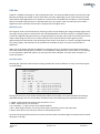
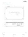
Expansion connector
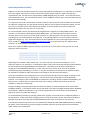
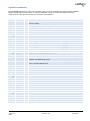
The EXPANSION connector on the rear of LabSat 3 gives access to a number of signals including CAN Bus,
RS232, 1PPS & Digital input/output. Accessory RLACS202 is used to provide user signal access for
integration into the users test system. Pin functions are as follows:Number Name
1 1PPS
2
3
4
5
6
7
8
9
10
11
12
13
14
15
16
17
DIGO
DIGI
CAN 1 H
CAN 1 L
CAN 2 H
CAN 2 L
I2C SDA
I2C SCL
I2C VCC
RS232 Tx
I/O
O
O
I
18 RS232 Rx
I
19
20
21
22
23
24
25
26
27
28
29
30
31
32
33
34
35
36
O
O
O
CAN Bus High Channel 1 – Standard ISO11898 voltage signal levels for CAN
CAN Bus Low Channel 1 – Standard ISO11898 voltage signal levels for CAN
CAN Bus High Channel 2 – Standard ISO11898 voltage signal levels for CAN
CAN Bus Low Channel 2 – Standard ISO11898 voltage signal levels for CAN
I2C Bus Data – Reserved for future use
I2C Bus Clock – Reserved for future use
I2C Bus voltage level – Reserved for future use
RS232 data output. NMEA Data from GNSS monitor or User RS232 data if
enabled. Standard RS232 Level.
User RS232 data which is recorded if RS232 is enabled in Digital configuration
menu. Standard RS232 Level.
Ground Connection
Ground Connection
Ground Connection
I/O
I/O
I/O
I/O
Reserved
Reserved
Reserved
Reserved
O
O
O
O
Ground Connection
Ground Connection
Connected to input power – Max 250mA
Connected to input power – Max 250mA
Page | 15
2015
Ground
Ground
Ground
IO_0
IO_1
IO_2
IO_3
Ground
Ground
Power
Power
I/O
I/O
I/O
I/O
I/O
I/O
I/O
O
Function
Signal from Internal GNSS monitor. Becomes active when monitor is locked.
5V Level. 25mA
User digital output. 5V Level. 25mA max
User digital input. Up to 12 V input level. Detection threshold=2.5V
Revision 1.4
15 January