1
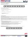
OR CAN BE USED CALCULATED METHOD WITHOUT TABLE
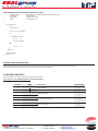
/*
ModBus_CRC16
Input *Buffer
Input Length
Output
Calculatd CRC16 with polynome 0xA001 and init value 0xFFFF
- pointer on data
- number byte in buffer
- calculated CRC16
*/
/*
cur_crc=0xFFFF;
do
{
unsigned int i = 8;
cur_crc = cur_crc ^ *Buffer++;
do
{
if (0x0001 & cur_crc)
{
cur_crc →→= 1;
cur_crc ^= 0xA001;
}
else
{
cur_crc →→= 1;
}
}
while (--i);
}
while (--Length);
return cur_crc;
*/
2. Read commands structure
The master communication device can send commands to the module to read its status and setup or the measured values, status and setup relevant to the combined
counter. More registers can be read, at the same time, sending a single command, only if the registers are consecutive (see chapter 5).
According to the used MODBUS protocol mode, the read command is structured as follows.
2.1 MODBUS ASCII/RTU
Values contained both in Query or Response messages are in hex format.
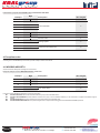
Query example in case of MODBUS ASCII/RTU: 010300020002D00B
Byte
Description
No. of bytes
01
Slave address
1
03
Function code
1
Starting register
2
No. of words to be read
2
Error check (CRC)
2
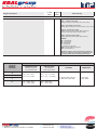
Example
00
High
02
Low
00
High
02
Low
D0
High
0B
Low
© KRALgroup
Meinlinova 309 CZ-190 16 Praha 9 - Koloděje
+420 602 360 502
+420 602 360 501
+420 281 970 988
http://www.kralgroup.cz
[email protected]
[email protected]
030EM05