1
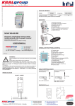
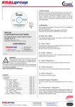
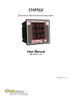
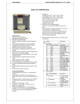
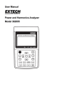
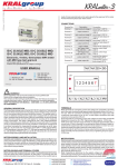
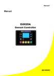
© KRALgroup - N_a 20120607 - NOVA 80 MID (1MTOEC80T001) OVERVIEW 3 2 1 MID B+D 1. Neutral terminal for 4 wire models 2. Tariff input terminals 3. Terminals for the two S0 outputs 4. UP key 5. ENTER key 6. Metrological LED 7. Current and voltage terminals 8. Safety-sealing (DO NOT REMOVE) 9. Optical COM port 10. Backlight LCD display 4 9 5 10 .cz 8 6 7 .cz .cz NOVA 80 MID LA SEA BLE A MIN TER RS! OVE L C 80A three phase energy meter, 4-quadrants with MID verification with changes valid to: 07.06.2012 Features and specifications are subject to change. SYMBOLS ON FRONT PANEL (EXAMPLE) USER MANUAL : 602 360 501(2) : 281 970 988 : [email protected] http://www.kralgroup.cz Meinlinova 309 CZ-190 16 Praha 9 - Koloděje © KRALgroup ! A. Company logo B. Device name C. Serial number D. Data Matrix E. Metrological LED symbol F. Protection class G. Meter constant (Metrological LED) H. Base current (max current) I. Working temperature J. Accuracy class K. Nominal voltage/frequency L. Wiring type A B C N D E F M G L K J I H WARNING! Device installation and use must be carried out only by qualified staff. Switch off the voltage before device installation. The content and the technical specification of this User Manual are subject to change without prior notice. They do not represent any contractual obligation. KEEP THIS INSTRUCTION MANUAL - CONTAINS, I.A., EU-DECLARATION OF CONFORMITY =3phase 4 wires, M. MID approval symbols N. Type approval certification = 3phase 3 wires CABLE STRIPPING LENGTH Connection measuring terminals (A & V) AVAILABLE MODELS Voltage Frequency MID certified 3x400 V 3x230/400 V 50Hz ▪ ▪ NOVA 80 MID - 3L NOVA 80 MID - 4L 5 mm Use a blade screwdriver with 0.8x3.5 mm size. 15 mm Use a PZ2 screwdriver. In all device models, partial counters are resettable. WIRING DIAGRAMS 3 PHASES - 4 WIRES N 1 3 2 4 5 L1 L2 A A-V N 6 A-V 1 3 2 S0-1 4 5 6 z p.c ou r g AL KR L3 A S0-2 Tarif z p.c ou r g AL KR A-V DIMENSIONS (mm) 3 PHASES - 3 WIRES S0-1 L1 A A-V L1 L1 L2 L2 L3 L3 L2 A A-V .cz 90 S0-2 Tarif L3 A 0,5 Nm 2 Nm A-V .cz A 45 Model S0 output / tariff terminals connection N The meter works properly even if only one phase is connected. In this wiring the backlight is disabled for energy saving reasons. 44 72 65 © KRALgroup Meinlinova 309 CZ-190 16 Praha 9 - Koloděje +420 602 360 502 +420 602 360 501 +420 281 970 988 http://www.kralgroup.cz [email protected] [email protected] 003TPn SYMBOLS ON DISPLAY MEASUREMENTS Display test can be carried out by pressing for 10 s and ▲ simultaneously. MEASURE UNIT DIS- COM S0 PLAY PORT OUTPUT INSTANTANEOUS VALUES DESCRIPTION SYMBOL SYMBOL Correct phase sequence (123) Voltage (Phase-0) Line voltage (Phase-Phase) Current VΣ - VL1-N - VL2-N - VL3-N V ● VL1-L2 - VL2-L3 - VL3-L1 V ● IΣ - I1 - I2 - I3 - IN A ! Wrong phase sequence (132) ! Undefined phase sequence (i.e. one or two phases are missing) Power factor PFΣ - PFL1 - PFL2 - PFL3 Apparent power SΣ - SL1 - SL2 - SL3 System value Active power PΣ - PL1 - PL2 - PL3 kW Reactive power QΣ - QL1 - QL2 - QL3 kvar Frequency f Hz Phase sequence CW/CCW ● ● Power direction IMP/EXP (Supply/Delivery) ● ● Ʃ L1 L2 L3 Metrological parameters corrupted (Code: XX will be displayed in the main area). The counter cannot be used and it must be returned to the Manufacturer. ! ERR 1 Value phase number 2 Active S0 output number Delivered (→), supplied (←) power or energy value Identify the Setup page (SETUP) or the Info page (INFO) COM Communication ON status SETUP page Capacitive / inductive value BAL PAR T1 T2 MkVAhMkWhMkvarh Measuring unit area (Σ) kvarh (Σ) Σ - L1 - L2 - L3 kVAr (Σ) Σ kWh, kvarh, kVAh Σ kWh, kvarh, kVAh Energy balance Σ kWh, kvarh, kVAh OTHER INFORMATION SYMBOL Present tariff T Undervoltage/overvoltage VOL, VUL VALUE / STATUS 1/2 DIS- COM PLAY PORT ● ON/OFF ● ON/OFF ● ON/OFF ● START/STOP ● COM ON/OFF ● Active S0 pulse S0-1, S0-2 ON/OFF ● Error condition ERR 01/02 ● Active communication LEGEND: ● = STANDARD ■ ● ● = BIDIRECTIONAL VALUE All the system counters (Σ) programmable for S0 outputs are shown in “SO OUTPUT” column. It is not allowed to set the same counter for both outputs. NOTE: in case of 3 wires model, phase-neutral voltages, neutral current, phase powers, phase power factors parameters and all phase counters are not available. KEY PRESS TIME WHERE Scroll loops Any page except for Setup Instantaneous Access Setup pages “Setup?” page >3 s Confirm a value/digit Setup pages Instantaneous Display test kWh Σ - L1 - L2 - L3 Balance counter value HOW TO Scroll pages in a loop Change a value/digit Start/stop the displayed partial counter Reset the displayed partial counter value Σ - L1 - L2 - L3 Underfrequency/overfreque fOL, fUL ncy PAR Partial counters KEY FUNCTIONS Exit Setup pages Total active energy Total reactive energy ind. and cap. Total apparent energy ind. and cap. T1/T2 tariff energy Resettable partial energy counters Undercurrent / overcurrent IOL, IUL 1 or 2 tariff counter value ● RECORDED DATA Main area Partial counter value. If flashing, the counter is stopped. ● kVA Setup pages Any loops page Setup pages >3 s Instantaneous Instantaneous Partial counters pages Instantaneous Partial counters pages >3 s BALANCE COUNTER VALUES CALCULATION BALANCE COUNTER FORMULA kWh [kWh T1] ‒ [kWh T1] + [kWh T2] ‒ [kWh T2] kVAh ind [kVAh ind T1] ‒ [kVAh ind T1] + [kVAh ind T2] ‒ [kVAh ind T2] kVAh cap [kVAh cap T1] ‒ [kVAh cap T1] + [kVAh cap T2] ‒ [kVAh cap T2] kvarh ind [kvarh ind T1] ‒ [kvarh ind T1] + [kvarh ind T2] ‒ [kvarh ind T2] kvarh cap [kvarh cap T1] ‒ [kvarh cap T1] + [kvarh cap T2] ‒ [kvarh cap T2] METROLOGICAL LED AND PULSES ON S0 OUTPUT METROLOGICAL LED PULSES S0 PULSES Any page except for Setup >10 s 1000 Imp./kWh 100 Imp./kWh & Imp./kvarh & Imp./kVAh © KRALgroup Meinlinova 309 CZ-190 16 Praha 9 - Koloděje +420 602 360 502 +420 602 360 501 +420 281 970 988 http://www.kralgroup.cz [email protected] [email protected] 003TPn PAGE STRUCTURE SETUP PAGES Device pages are grouped in 7 loops. Press ▲ to scroll pages in a loop. SETUP ACCESS PAGE LOOP 1: TARIFF 1 COUNTERS VALUES L1 1 2 >3 s T1 LOOP 2: TARIFF 2 COUNTER VALUES L1 1 MODBUS ADDRESS (01...F7 Hex) Available only in case of combined RS485 module 1. Press , the first digit will start to flash. 2. Press to change the value. 3. Confirm with . 4. Repeat points 2 and 3 for the next digit. LOOP 7: DEVICE INFO 2 MBUS PRIMARY ADDRESS (0...250) Available only in case of combined MBUS module 1. Press , the first digit will start to flash. 2. Press to change the value. 3. Confirm with . 4. Repeat points 2 and 3 for the next digit. T2 LOOP 3: TOTAL COUNTER VALUES L1 1 LOOP 6: SETUP MBUS SECONDARY ADDRESS (0...99999999) Available only in case of combined MBUS module 1. Press , the first digit will start to flash. 2. Press to change the value. 3. Confirm with . 4. Repeat points 2 and 3 for the next digit. 2 LOOP 4: PARTIAL AND BALANCE COUNTER VALUES Ʃ 1 LOOP 5: REALTIME VALUES L1 2 1 2 MODBUS MODE (RTU=8N1, ASCII=7E2) Available only in case of combined RS485 module 1. Press , the item will start to flash. 2. Press to change the item. 3. Confirm with . PAR NOTE: in case of 3 wires model, pages showing phase values are not available. COMMUNICATION SPEED Page and range available according to the combined communication module 1. Press , the value will start to flash. 2. Press to change the value. 3. Confirm with . HOW TO START / STOP / RESET PARTIAL COUNTERS COUNTER ASSIGNED TO S0 OUTPUT (1-2) 1. Press , the items which identify the counter (e.g. →, kWh) will start to flash. 2. Press to change the counter to be assigned to the output. 3. Confirm with . Ʃ Feature available only on partial counter pages. HOW TO START DISPLAYED PARTIAL COUNTER Ʃ 1 Ʃ 2 PAR PAR 1 2 PAR Ʃ kVAh HOW TO STOP DISPLAYED PARTIAL COUNTER PREVIOUSLY STARTED Ʃ 1 Ʃ 2 PAR PAR 1 2 ALL PARTIAL COUNTERS RESET 1. Press , a new page for confirmation will be displayed. 2. Press to change the flashing value, Y to confirm the reset, N to cancel. 3. Confirm with . PAR PAR HOW TO RESET DISPLAYED PARTIAL COUNTER Ʃ PAR 1 2 >3s Ʃ PAR 1 2 PAR >3 s In START?, STOP?, RESET?, pages, selectable items are: Y=to confirm, N=to cancel. To change item, press ▲. ON ANYSETUP PAGE EXIT FROM SETUP 1. Press to change the flashing value, Y to exit and save the settings, N to exit without saving, C to continue scrolling setup first page. 2. Confirm with . © KRALgroup Meinlinova 309 CZ-190 16 Praha 9 - Koloděje +420 602 360 502 +420 602 360 501 +420 281 970 988 http://www.kralgroup.cz [email protected] [email protected] 003TPn INFO PAGES ENVIRONMENTAL CONDITIONS Mechanical environmental Electromagnetic environmental Operating temperature Storage temperature Relative humidity (without condensation) Sinusoidal vibration amplitude Up to 4 INFO pages can be displayed to show details about: 1. counter firmware version 2. checksum 3. combined communication module in use 4. full scale value (FSA) The third page, which shows communication module in use, can change according to the module combined with the counter (see table). If the counter has no combined module this page will not be displayed. COMBINED COMMUNICATION MODULE RS485 MODBUS DETAIL DISPLAYED ON THE INFO PAGE Mbus LAN GATEWAY EIB/KNX i.V IP 20 WASTE DISPOSAL Lan (no info - in preparation) EU-DECLARATION OF CONFORMITY Product name: THREE-PHASE STATIC WATT-HOUR METER OF ACTIVE ENERGY Type designation: NOVA 80 MID - 4L NOVA 80 MID - 3L TECHNICAL FEATURES Data are in compliance with standards IP 51 This product may not be, at the end of its useful life, disposed of with normal household waste but must be returned to a collection point for recycling of electronic equipment. Please check with your dealer or local authorities for disposal of the competent authority. Modbus M-BUS Protection degree - frontal part (granted only in case of installation in a cabinet with at least IP51 protection degree) Protection degree - terminals M1 E2 -25°C ... +55°C -25°C ... +75°C max. 80% 50 Hz ±0,075 mm EC-Type test certificate: 154/MID (NOVA 80 MID - 4L) 155/MID (NOVA 80 MID - 3L) EN50470-1, EN 50470-3, EN 62053-23, EN 62053-31 GENERAL Housing in compliance with standard DIN 43880 Terminals in compliance with standard EN 60999 AUXILIARY POWER SUPPLY Power supplied from the voltage circuit Nominal measurement voltage ±20% Consumption (for each phase) 7,5 VA max. Nominal frequency 50 Hz VOLTAGE/FREQUENCY AND WIRING MODES MODEL WIRING V f NOVA 80 MID - 3L 3 phases 3 wires 3x400 V 50 Hz NOVA 80 MID - 4L 3 phases 4 wires 3x230/400 V CURRENT (A) Maximum current Imax 80 A Basic current Iref (Ib) 5A Ratio current Itr 500 mA Minimum current Imin 250 mA Starting current Ist 20 mA ACCURACY Active energy class B according to EN 50470-3 Reactive energy class A according to EN 62053-23 2 S0 OUTPUTS Passive optoisolated Maximum values (in compliance with EN 62053-31) 250 VAC-DC - 100 mA 50 ±2ms ON time Pulse length min. 30 ±2ms OFF time TARIFF INPUT Active optoisolated Min.-max. voltage 80...276 V(AC-DC) METROLOGICAL LED Meter constant 1000 Imp./kWh WIRE DIAMETER FOR TERMINALS Measuring terminals (A & V) 1,5...35 mm2 S0 output / tariff terminals 0,14...2,5 mm2 SAFETY ACCORDING TO EN 50470-1 STANDARD Indoor installation Pollution degree 2 Protective class (EN 50470-1) II Pulse voltage test 1,2/50μs 6kV AC voltage test (EN 50470-3, 7.2) 4 kV Housing material flame resistance UL 94 class V0 Number and address of notified person: (Modul B+D) 0051 IMQ SpA Via Quintiliano 43 I-20138 MILANO Metrology marking: СЄ-M13-0051 The watt-hour meters NOVA 80 MID - 4L and NOVA 80 MID - 3L meet the requirements of EN50470-1, EN 50470-3, EN 62053-23, EN 62053-31 of both current direction of class B for active energy and of class A for reactive energy for direct connection into the three-phase electricity network. Potential-free-pulse-transmitter complies with DIN EN 62053-31 standard for installation of broadcasting impulses for Class A and B for the transmitter of type "S0". The kWh meter corresponds to a tariff metering in the way its connection to the three-phase electricity network. The external dimensions of the meter corresponds to the built-in devices of a 4modules (4-TE) size according to DIN 43880 standard. Installation of the energy meters is designed for mounting on a standard DIN-rail 35 mm wide according to DIN EN 50022 standard. The electric protection class of the energy meters with terminal covers corresponds to IP51 according to DIN EN 60529 standard. Prague, 22.10.2013 Your partner for measuring the energy DIN RAIL MOUNTED kWh METERS RE/CONDITIONED kWh METER PRE/PAZMENT kWh METERS CREDIT CARDS kWh METERS GSM OPERATED kWh METERS SPECIAL kWh METERS OTHERS FOR THE MEASUREMENT OF EL. ENERGY CURRENT TRANSFORMERS MEASURING POWER IN HARBORS AND ANCHORAGE SHIP (MARINAS) MEASURING POWER IN THE CAMP, IN TRADE FAIR, EXHIBITION, BUSINESS, COMMERCIAL AND ADMINISTRATIVE CENTERS ENERGY MANAGEMENT SYSTEMS (M-Bus, PLC, GSM, RS-485, EIB, INSTA-BUS) Our advice is for You with pleasure © KRALgroup Meinlinova 309 CZ-190 16 Praha 9 - Koloděje +420 602 360 502 +420 602 360 501 +420 281 970 988 http://www.kralgroup.cz [email protected] [email protected] 003TPn