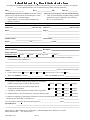
1
HIGHWAY ADDRESSABLE
REMOTE TRANSDUCER
(HARTÒ)
DEVICE INTERFACE
Part No. 392930-01-3
(For Models 33XX)
For The Following BBI Instruction Manuals:
CI-3305, CI-3310, CI-3330 & CI3335
Bristol Babcock
Product Information Package
PIP-HART33XX - January 2003
NOTICE
Copyright Notice
The information in this document is subject to change without notice. Every effort has been
made to supply complete and accurate information. However, Bristol Babcock assumes no
responsibility for any errors that may appear in this document.
Request for Additional Instructions
Additional copies of instruction manuals may be ordered from the address below per attention of the Sales Order Processing Department. List the instruction book numbers or give
complete model number, serial or software version number. Furnish a return address that
includes the name of the person who will receive the material. Billing for extra copies will
be according to current pricing schedules.
HART® is a registered trademark of the HART Communication Foundation, Austin, Texas
USA. ACCOL™ is a trademark of Bristol Babcock. Other trademarks or copyrighted
products mentioned in this document are for information only, and belong to their respective
companies, or trademark holders.
Copyright (c) 2003, Bristol Babcock, 1100 Buckingham St., Watertown, CT 06795. No part of
this manual may be reproduced in any form without the express written permission of
Bristol Babcock.
IMPORTANT! READ INSTRUCTIONS BEFORE STARTING!
Be sure that these instructions are carefully read and understood before any
operation is attempted. Improper use of this device in some applications may result
in damage or injury. The user is urged to keep this book filed in a convenient
location for future reference.
These instructions may not cover all details or variations in equipment or cover
every possible situation to be met in connection with installation, operation or
maintenance. Should problems arise that are not covered sufficiently in the text, the
purchaser is advised to contact Bristol Babcock for further information.
EQUIPMENT APPLICATION WARNING
The customer should note that a failure of this instrument or system, for
whatever reason, may leave an operating process without protection. Depending
upon the application, this could result in possible damage to property or injury to
persons. It is suggested that the purchaser review the need for additional backup
equipment or provide alternate means of protection such as alarm devices, output
limiting, fail-safe valves, relief valves, emergency shutoffs, emergency switches, etc.
If additional information is required, the purchaser is advised to contact Bristol
Babcock.
RETURNED EQUIPMENT WARNING
When returning any equipment to Bristol Babcock for repairs or evaluation,
please note the following: The party sending such materials is responsible to ensure
that the materials returned to Bristol Babcock are clean to safe levels, as such levels
are defined and/or determined by applicable federal, state and/or local law
regulations or codes. Such party agrees to indemnify Bristol Babcock and save
Bristol Babcock harmless from any liability or damage which Bristol Babcock may
incur or suffer due to such party's failure to so act.
ELECTRICAL GROUNDING
Metal enclosures and exposed metal parts of electrical instruments must be
grounded in accordance with OSHA rules and regulations pertaining to "Design
Safety Standards for Electrical Systems," 29 CFR, Part 1910, Subpart S, dated: April
16, 1981 (OSHA rulings are in agreement with the National Electrical Code).
The grounding requirement is also applicable to mechanical or pneumatic
instruments that include electrically-operated devices such as lights, switches, relays,
alarms, or chart drives.
EQUIPMENT DAMAGE FROM ELECTROSTATIC DISCHARGE VOLTAGE
This product contains sensitive electronic components that can be damaged by
exposure to an electrostatic discharge (ESD) voltage. Depending on the magnitude
and duration of the ESD, this can result in erratic operation or complete failure of the
equipment. Read BBI supplemental document S14006 for proper care and handling
of ESD-sensitive components.
Bristol Babcock 1100 Buckingham Street, Watertown, CT 06795
Telephone (860) 945-2200
WARRANTY
A.
Bristol warrants that goods described herein and manufactured by Bristol are free
from defects in material and workmanship for one year from the date of shipment
unless otherwise agreed to by Bristol in writing.
B.
Bristol warrants that goods repaired by it pursuant to the warranty are free from
defects in material and workmanship for a period to the end of the original warranty
or ninety (90) days from the date of delivery of repaired goods, whichever is longer.
C.
Warranties on goods sold by, but not manufactured by Bristol are expressly limited
to the terms of the warranties given by the manufacturer of such goods.
D.
All warranties are terminated in the event that the goods or systems or any part
thereof are (i) misused, abused or otherwise damaged, (ii) repaired, altered or
modified without Bristol's consent, (iii) not installed, maintained and operated in
strict compliance with instructions furnished by Bristol, or (iv) worn, injured or
damaged from abnormal or abusive use in service time.
E.
THESE WARRANTIES ARE EXPRESSLY IN LIEU OF ALL OTHER
WARRANTIES EXPRESS OR IMPLIED (INCLUDING WITHOUT LIMITATION
WARRANTIES AS TO MERCHANTABILITY AND FITNESS FOR A PARTICULAR
PURPOSE), AND NO WARRANTIES, EXPRESS OR IMPLIED, NOR ANY
REPRESENTATIONS, PROMISES, OR STATEMENTS HAVE BEEN MADE BY
BRISTOL UNLESS ENDORSED HEREIN IN WRITING. FURTHER, THERE ARE
NO WARRANTIES WHICH EXTEND BEYOND THE DESCRIPTION OF THE
FACE HEREOF.
F.
No agent of Bristol is authorized to assume any liability for it or to make any written
or oral warranties beyond those set forth herein.
REMEDIES
A.
Buyer's sole remedy for breach of any warranty is limited exclusively to repair or
replacement without cost to Buyer of any goods or parts found by Seller to be
defective if Buyer notifies Bristol in writing of the alleged defect within ten (10) days
of discovery of the alleged defect and within the warranty period stated above, and if
the Buyer returns such goods to Bristol's Watertown office, unless Bristol's Watertown office designates a different location, transportation prepaid, within thirty (30)
days of the sending of such notification and which upon examination by Bristol
proves to be defective in material and workmanship. Bristol is not responsible for
any costs of removal, dismantling or reinstallation of allegedly defective or defective
goods. If a Buyer does not wish to ship the product back to Bristol, the Buyer can
arrange to have a Bristol service person come to the site. The Service person's
transportation time and expenses will be for the account of the Buyer. However,
labor for warranty work during normal working hours is not chargeable.
B.
Under no circumstances will Bristol be liable for incidental or consequential damages
resulting from breach of any agreement relating to items included in this quotation
from use of the information herein or from the purchase or use by Buyer, its
employees or other parties of goods sold under said agreement.
How to return material for Repair or Exchange
Before a product can be returned to Bristol Babcock for repair, upgrade, exchange, or to
verify proper operation, form (GBU 13.01) must be completed in order to obtain a RA
(Return Authorization) number and thus ensure an optimal lead time. Completing the form
is very important since the information permits the Bristol Babcock Repair Dept. to
effectively and efficiently process the repair order.
You can easily obtain a RA number by:
A. FAX
Completing the form (GBU 13.01) and faxing it to (860) 945-3875. A BBI Repair
Dept. representative will return call (or other requested method) with a RA number.
B. E-MAIL
Accessing the form (GBU 13.01) via the Bristol Babcock Web site
(www.bristolbabcock.com) and sending it via E-Mail to [email protected].
A BBI Repair Dept. representative will return E-Mail (or other requested method)
with a RA number.
C. Mail
Mail the form (GBU 13.01) to
Bristol Babcock Inc.
Repair Dept.
1100 Buckingham Street
Watertown, CT 06795
A BBI Repair Dept. representative will return call (or other requested method) with
a RA number.
D. Phone
Calling the BBI Repair Department at (860) 945-2442. A BBI Repair Department
representative will record a RA number on the form and complete Part I, then send
the form to the Customer via fax (or other requested method) for Customer
completion of Parts II & III.
A copy of the completed Repair Authorization Form with issued RA number should be included with the product being returned. This will allow us to quickly track, repair, and
return your product to you.
&VMWXSP &EFGSGO -RG 6ITEMV %YXLSVM^EXMSR *SVQ
(Providing this information will permit BBI to effectively and efficiently process your return. Completion is required to
receive optimal lead time. Lack of information may result in increased lead times.)
Date___________________
RA #___________________SH_
Standard Repair Practice is as follows: Variations to this is
practice may be requested in the “Special Requests” section.
• Evaluate / Test / Verify Discrepancy
• Repair / Replace / etc. in accordance with this form
• Return to Customer
Part I
Line No.____________
Please be aware of the Non warranty standard charge:
• There is a $100 minimum evaluation charge, which is
applied to the repair if applicable (√ in “returned”
B,C, or D of part III below)
Please complete the following information for single unit or multiple unit returns
Address No.
(office use only) Address No.
(office use only)
Bill to :
Ship to:
Purchase Order:
Contact Name:____________________________________
Phone:
Fax:
Part II
E-Mail:
Please complete Parts II & III for each unit returned
Model No./Part No.
Description
Range/Calibration
S/N
Reason for return :
1.
Failure
Upgrade
Verify Operation
Other
Describe the conditions of the failure (Frequency/Intermittent, Physical Damage, Environmental Conditions,
Communication, CPU watchdog, etc.)
(Attach a separate sheet if necessary)
2.
Comm. interface used:
3.
What is the Firmware revision? _____________________ What is the Software &version?
Standalone
RS-485
Ethernet
Modem (PLM (2W or 4W) or SNW)
Other:______________
Part III If checking “replaced” for any question below, check an alternate option if replacement is not available
A. If product is within the warranty time period but is excluded due
to BBI’s warranty clause, would you like the product:
repaired
returned
replaced
scrapped?
B. If product were found to exceed the warranty period,
would you like the product:
repaired
returned
replaced
scrapped?
C. If product is deemed not repairable would you like your product:
returned
replaced
scrapped?
D. If BBI is unable to verify the discrepancy, would you like the product:
returned
replaced
*see below?
* Continue investigating by contacting the customer to learn more about the problem experienced? The person to contact
that has the most knowledge of the problem is:
_______________________________ phone
If we are unable to contact this person the backup person is: _________________________ phone
Special Requests:
Ship prepaid to: Bristol Babcock Inc., Repair Dept., 1100 Buckingham Street, Watertown, CT 06795
Phone: 860-945-2442
Fax: 860-945-3875
Form GBU 13.01
Rev. A
Bristol Babcock
Training
GET THE MOST FROM YOUR BRISTOL
BABCOCK INSTRUMENT OR SYSTEM
● Avoid Delays and problems in getting your system on-line
● Minimize installation, start-up and maintenance costs.
● Make the most effective use of our hardware and software.
● Know your system.
As you know, a well-trained staff is essential to your operation. Bristol Babcock offers a full
schedule of classes conducted by full-time, professional instructors. Classes are offered
throughout the year at four locations: Houston, Birmingham, Orlando and our Watertown,
CT headquarters. By participating in our training, your personnel can learn how to install,
calibrate, configure, program and maintain any and all Bristol Babcock products and realize
the full potential of your system.
For information or to enroll in any class, contact our training department in Watertown at
(860) 945-2269. For Houston classes, you can also contact our Houston office, at (713) 6856200.
A Few Words About Bristol Babcock
For over 100 years, Bristol7 has been providing innovative solutions for the measurement
and control industry. Our product lines range from simple analog chart recorders, to
sophisticated digital remote process controllers and flow computers, all the way to turnkey
SCADA systems. Over the years, we have become a leading supplier to the electronic gas
measurement, water purification, and wastewater treatment industries.
On off-shore oil platforms, on natural gas pipelines, and maybe even at your local water
company, there are Bristol Babcock instruments, controllers, and systems running year-in
and year-out to provide accurate and timely data to our customers.
Getting Additional Information
In addition to the information contained in this manual, you may receive additional assistance in using this product from the following sources:
Contacting Bristol Babcock Directly
Bristol Babcock's world headquarters are located at 1100 Buckingham Street, Watertown,
Connecticut 06795, U.S.A.
Our main phone numbers are:
(860) 945-2200
(860) 945-2213 (FAX)
Regular office hours are Monday through Friday, 8:00AM to 4:30PM Eastern Time,
excluding holidays and scheduled factory shutdowns. During other hours, callers may leave
messages using Bristol's voice mail system.
Telephone Support - Technical Questions
During regular business hours, Bristol Babcock's Application Support Group can provide
telephone support for your technical questions.
For technical questions about TeleFlowÔ products call (860) 945-8604.
For technical questions about ControlWave call (860) 945-2244 or (860) 945-2286.
For technical questions regarding Bristol’s OpenEnterprise product, call (860) 945-2501 or
e-mail: [email protected]
For technical questions regarding ACCOL products, Open BSI Utilities, as well as
Bristol's Enterprise Server7/Enterprise Workstation7 products, call (860) 945-2286.
For technical questions about Network 3000 hardware, call (860) 945-2502.
You can e-mail the Application Support Group at: [email protected]
The Application Support Group maintains an area on our web site for software updates and
technical information. Go to: www.bristolbabcock.com/services/techsupport/
For assistance in interfacing Bristol Babcock hardware to radios, contact Bristol Babcock’s
Communication Technology Group in Orlando, FL at (407) 629-9463 or (407) 6299464.
Telephone Support - Non-Technical Questions, Product Orders, etc.
Questions of a non-technical nature (product orders, literature requests, price and delivery
information, etc.) should be directed to the nearest sales office (listed on the rear cover) or to
your Bristol-authorized sales representative. A list of
Please call the main Bristol Babcock number (860-945-2200) if you are unsure which office
covers your particular area.
Visit our Site on the World Wide Web
For general information about Bristol Babcock and its products, please visit our site on the
World Wide Web at: www.bristolbabcock.com
Training Courses
Bristol Babcock’s Training Department offers a wide variety of courses in Bristol hardware
and software at our Watertown, Connecticut headquarters, and at selected Bristol regional
offices, throughout the year. Contact our Training Department at (860) 945-2269 for course
information, enrollment, pricing, and scheduling.
PIP-HART33XX
HIGHWAY ADDRESSABLE REMOTE TRANSDUCER
(HART®)
DEVICE INTERFACE
TABLE OF CONTENTS
SECTION
TITLE
PAGE #
Section 1 - INTRODUCTION
1.1
1.2
1.3
1.4
1.4.1
1.4.2
1.4.3
GENERAL INTRODUCTION......................................................................................................... 1
FEATURES...................................................................................................................................... 1
THEORY .......................................................................................................................................... 1
HDI DESCRIPTION ....................................................................................................................... 2
HDI Board Connectors .................................................................................................................... 2
HDI Board Status LEDs ................................................................................................................. 3
HDI Board Circuitry........................................................................................................................ 4
Section 2 - CONFIGURATION & CONNECTIONS
2.1
2.1.1
2.1.2
2.2
2.2.1
2.2.2
2.2.3
2.2.3.1
2.2.3.2
RESTRICTIONS & ASSUMPTIONS ............................................................................................. 7
HART Slave Devices........................................................................................................................ 7
3508 Smart Transmitters ............................................................................................................... 7
CONFIGURAING A SINGLE HDI BOARD .................................................................................. 8
RS-485 Interface - To a Single HDI Board..................................................................................... 8
RS-232 Interface - To a Single HDI Board................................................................................... 10
Configuring Multiple HDI Assemblies into a Single 33XX Master ............................................ 11
Multiple HDI Boards Configured for RS-485 Operation ............................................................. 11
Multiple HDI Boards Configured for RS-232 Operation ............................................................. 13
Section 3 - SPECIFICATIONS
3.1
3.2
3.3
3.4
3.5
3.6
HART COMMUNICATION PROTOCOL PARAMETERS
FOR PHYSICAL LINK ................................................................................................................. 15
HART DEVICE IMPEDANCE SPECIFICATION....................................................................... 15
HART DEVICE POWER SUPPLY REQUIREMENTS ............................................................... 15
PHASE SHIFT SPECIFICATION................................................................................................ 15
PERFORMANCE SPECIFICATION............................................................................................ 15
ENVIRONMENTAL SPECIFICATION ....................................................................................... 16
SUPPLEMENTS
Special Instructions for Class I, Division 2 Hazardous Locations............................... Appendix A
REFERENCE DOCUMENTS
(Note: These documents are not provided in this manual)
BBI HART MASTER PROTOCOL MANUAL........................................................................D4068
BBI ACCOL II REFERENCE MANUAL ...............................................................................D4044
HART® FSK PHYSICAL LAYER SPECIFICATION HART® Communication Foundation Document Number .......................................HCF_SPEC-54
PIP-HART33XX
Page 0-1
Table Of Contents
Section 1
INTRODUCTION
1.1 GENERAL INTRODUCTION
Note: HART® is a registered trademark of the HART® Communication
Foundation of Austin, Texas, USA. Any time the term ‘HART’ is
used hereafter in this document, the term implies the registered
trademark.
Highway Addressable Remote Transducer (HART) Device Interfaces (HDI) allows HART
slave devices or BBI 3508 transmitters to communicate with a BBI Series 33XX DPC/RTU,
i.e., 3305s, 3310s, 3330s, and 3335s. The HDI supports RS-232 and RS-485 interfaces. The
interface to the field devices is composed of a jumper selectable 249 ohm resistor in parallel
with an AC coupled transformer. An HART/TIB ACCOL Custom Module and the configuration of a host (33XX) communications port as a custom port in ‘HART mode’ are
required to support the protocol (Data Link Layer) for HART devices. The ACCOL Master
Module is used to support RS-232 configured HDIs for communication with BBI 3508 transmitters. Each HDI can interface with up to 15 HART slave devices.
1.2 FEATURES
·
·
·
·
·
Selectable RS-232 or RS-485 Interface to DPC/RTU
Transformer Coupled Comm. Interface to HART devices
Operates from external 9 to 30 VDC power source
Usable with both HART slave devices and BBI 3508 transmitters. RS-232/RS-485 mode
of communications is valid for HART slave devices. RS-232 mode is valid for BBI 3508s.
Conforms to HART® FSK Physical Layer Specification.
1.3 THEORY
The BBI HART Device Interface (HDI) provides for master/slave communications, with the
master originating each transaction, and slaves only generating replies when prompted by
the master. HART allows for 2 ‘masters’ on a single link. The “Primary Master” is the
normal control-system master, and when required, a hand-held communicator can be used
as the “Secondary Master,” for maintenance purposes. Primary and secondary masters must
be configured to use separate addresses.
The BBI HDI board provides an RS-485/232 interface to a BBI 33XX DPC/RTU Communications Port and a two-wire (voltage sourced or current sourced) connection to a ‘HART
device’ or to a BBI 3508. Twisted-pair copper cable is used as the medium.
The HART Device Interface operates from 9 to 30 VDC bulk supply. The assembly supports
RS-232 or RS-485 interfaces to the host BBI 33XX DPC/RTU. The signals are TXD, RXD,
CTS, RTS and CD for RS-232 operations and +TXD, -TXD, +RXD and -RXD for RS-485
operation. Interface to the field device is composed of a jumper selectable 249 ohm resistor
in parallel with an AC coupled transformer. FSK signal amplitude during transmission is
between 400 to 600 mV with the average value of the FSK signal at 0 V. The HDI board
PIP-HART33XX
Page - 1
HART Device Interface
receiver input requires a signal that must be in the range of 120 mV to 1.5 V (Peak-to-Peak).
FSK signals from the field devices below 80 mV (Peak-to-Peak) will be ignored by the interface board.
1.4 HDI DESCRIPTION
The HART Adapter Interface Board is assembled in a DIN Rail Mounting Assembly. This
assembly measures 5.56” long by 4.37” in high by 1.06” deep. In addition to 8 selectable
jumpers and 4 status LEDs, the HDI Board contains three connectors (see Figures 1 & 10).
1.4.1 HDI Board Connectors
J1 - a 9-Pin D-Type Connector for the RS-232 Interface (see Table 1)
TB1 - a 6-Point Term. Block for the RS-485 Interface and the Input Power (see Table 2)
TB2 - a 2-Point Terminal Block for Slave Device Field Connections (see Table 3)
Figure 1 - HART Device Interface Assembly
PIP-HART33XX
Page - 2
HART Device Interface
Table 1 - RS-232 Interface Connector J1 Signal Identification
PIN #
1
2
3
5
6
7
RS-232 SIGNAL
DCD
/TXD
/RXD
GND
CTS
RTS
SIGNAL DESCRIPTION
Data Carrier Detect
Transmit Data NOT
Receive Data NOT
Ground
Clear to Send
Request to Send
DCE I/O
Output
Input
Output
Output
Input
Table 2 - Power & RS-485 Interface Connector TB1 Signal Identification
PIN #
1
2
3
4
5
6
NAME
VIN +9 - +28 VDC
GND
-RXD
+RXD
-TXD
+TXD
DESCRIPTION
Input Power (+)
Power Ground (-)
- TX Data from 33XX
+ TX Data from 33XX
- RX Data to 33XX
+ RX Data to 33XX
Table 3 - Slave Device Field Connector TB2 Signal Identification
PIN #
1
2
FIELD CONNECT
Field Loop (no polarity)
Field Loop (no polarity)
Table 4 - HDI Board Jumper Identification and Assignment
JUMPER #
DESCRIPTION
POS. 1-2
POS. 2-3
W1
RS-232 Mode
Disabled
N/A**
W2
3508 Mode (10 mS ON Delay)
Disabled
Enabled
W3
*RS-485 Rcvr. 120 ohm Terminator
Enabled
Disabled
W4
*RS-485 Rcvr. Positive Bias
Enabled
Disabled
W5
*RS-485 Rcvr. Negative Bias
Enabled
Disabled
W6
*RS-485 Xmtr. 120 ohm Terminator
Enabled
Disabled
W7
Status LED Enable
Enabled
Disabled
W8
249 Ohm Loop Resistor
Connected
Open
* = Install on RS-485 End Node
** = W1 is a 2 position Jumper, Installed = RS-232 Disabled/RS-485 Enabled,
Removed = RS-232 Enabled/RS-485 Disabled
1.4.2 HDI Board Status LEDs
There are four status LEDs on the HDI Board. LEDs CR14 through CR17 reflect the status
of the active states of Transmit Data NOT (/TXD), Receive Data NOT (/RXD), Data Carrier
Detect NOT (/DCD) and Request to Send NOT (/RTS). A logic “0” state of TXD or RXD will
PIP-HART33XX
Page - 3
HART Device Interface
light CR14 or CR15 respectively. The four LEDs can be disabled by placing jumper W7 in
position 2-3.
CR14 = /TXD (Transmit Data NOT)
CR15 = /RXD (Receive Data NOT)
CR16 = /DCD (Data Carrier Detect NOT)
CR17 = /RTS (Request to Send NOT)
1.4.3 HDI Board Circuitry
The HDI board has a built-in ±5V DC Switching Power Supply that is fused and operates
from a bulk 9V to 30V DC. A blocking diode protects the power supply circuitry from
reversed input power conditions.
Except for the Power Supply, the major components of the HART Device Interface board are
shown in the block diagram (Figure 2).
There are independent RS-232 and RS-485 transceivers which are jumper selectable. A 120
ohm biasing resistor is jumper selectable for the RS-485 transmit lines. A 120 ohm
terminator and biasing resistors are jumper selectable for the RS-485 receive lines.
TXD
20C12
BANDPASS
FILTER/
SWITCH
RTS485/232
RXD
DCD
RTS
GEN.
RTS
CONTROL
RS485
XMTR
RCVR
+TERM
TXD
RXD
DCD
RS485/
RS232
SELECT
RS232
RTS232
XMTR
DRIVE/
SWITCH
3508
RTS/CTS
10 MSEC
DELAY
CTS
RXD
DCD
+TX
-TX
+RX
-RX
RS232
XCEIVER
TXD
RXD
RTS
CTS
DCD
3508/HART
XFORMER
249 OHM/
JUMPER
Figure 2 - Block Diagram of BBI HDI Board
PIP-HART33XX
Page - 4
HART Device Interface
When the HDI is configured to communicate with slave devices which support the HART
protocol, and the communication mode between the HDI and the 33XX device is RS-232.
CTS NOT is asserted 100 microseconds after RTS NOT becomes valid. In the RS-485 mode,
RTS NOT is generated by a 1 to 0 transition of TXD. For BBI 3508 applications in RS-232
mode, a 10 millisecond RTS NOT to CTS NOT delay is selected to emulate the existing TIB
design. The added combination of RTS232 NOT and RTS485 NOT enables the 20C12 FSK
modem’s transmit circuitry, enables the CMOS switch to the transformer and disconnects
the receive signal to the FSK modem’s receiver.
The 20C12 FSK modem operates at Bell 202 standards with a 460.8 KHz clock. The
modulated CMOS digital signal from the 20C12 is scaled to a constant ±0.6V level via a
transformer drive circuit that provides a constant output signal with varying loads. The
transformer drive circuit is isolated from the output transformer with a CMOS switch. This
switch is only closed during transmission cycles. The received FSK signal is routed through
a doubler and bandpass filter to the FSK modem. A CMOS switch disconnects the filtered
signal from the input of the FSK receiver during transmit cycles.
The field side of the transformer is AC coupled with a 2.2 µF capacitor to the field devices
and to a jumper selectable 249 ohm load resistor.
RS-232 and RS-485 signals are transorb protected from surge transients and electo-static
discharge (ESD).
PIP-HART33XX
Page - 5
HART Device Interface
Section 2
CONFIGURATION & CONNECTIONS
2.1 RESTRICTIONS & ASSUMPTIONS
For multidrop configurations, the field devices are placed in a “digital mode” of operation
with the loop current for the device set at 4mA or less. The input impedance of the master in
receive mode is 249 ohms. The maximum number of field devices that can be placed in
parallel with a 24V supply is determined by the following equation: Max. # of Field devices
= {(24V - V(Field device) - [4mA x 249 x #(Field Devices)] - [4mA x #(Field devices) x Wire
Resistance] - 2Vloop} >0V. This calculation implies that the maximum number of transmitters, which require a minimum of 12V to operate in a loop, is 10 when the wire
resistance is not included. The power supply voltage must exceed 24V if more than 10 transmitters are to be connected in parallel. Note: The maximum number of transmitters that can
be connected in parallel is not to exceed 15.
Field devices with a maximum ID number of 15 cannot be mixed with field devices with a
maximum ID number of 2 24.
2.1.1 HART Slave Devices
The Carrier On Delay and Carrier Off Delay as specified in the HART Foundation Data
Link Layer specification, states that the delay from an idle line to/from an acceptable signal
level is 5 bit times maximum. For HDIs configured for RS-232 communications mode, the
carrier On delay will be met, but, the off delay may exceed the 5 bit time requirement (but
the delay will be less than 12 bit times). HART slave devices are required to send a
minimum of 5 preambles. The 20C12 FSK Modem located on the HDI board will output
receive data within 9 to 15 milliseconds after the transmit cycle is completed. At 1200 baud,
one character time is 11 x 0.833 milliseconds or 10 milliseconds. The slave device will start
to transmit the preamble one character time after the end of the last character sent from the
master device. The total delay from the end of the last character sent from the master to
valid receive data is 25 milliseconds. Since there is a 1 character delay from the HART
module, the receive communications driver will synchronize on the third preamble at the
latest. The receive communications driver for the HART ACCOL module requires one
preamble before the start of data.
For the RS-485 mode, the off delay will be between 12 to 18 milliseconds. This is equivalent
to 2 characters. The 20C12 FSK Modem takes 9 to 15 milliseconds to assert Carrier Detect
(CD) and valid data. The total delay is 33 milliseconds. The slave device will delay 1
character time, which is 9 milliseconds. The difference is 33 - 9.2 = 23.8 milliseconds. This is
about 2.6 characters. Two valid preambles will be seen by the receive communications
driver for the HART ACCOL module, which is sufficient before the start of data.
2.1.2 3508 Smart Transmitters
In the RS-232 communications mode, the HDI can operate properly with 3508 transmitters.
The 10 millisecond RTS/CTS delay must be selected.
PIP-HART33XX
Page - 6
HART Device Interface
With existing 33XX firmware, the HDI will not communicate with 3508 TELETRANS when
configured in the RS-485 communications mode. A programmable length preamble is
required.
2.2 CONFIGURING A SINGLE HDI BOARD
2.2.1 RS-485 Interface - To a Single HDI Board (see Figures 3, 4 & 5)
Note: The maximum length of an RS-485 cable should not exceed 4000 feet.
Follow steps 1 through 4 below to configure a single HDI assembly for RS-485/HART interface operation.
1. Install the HDI Assembly in a suitable location (DIN Rail mounted). Connect the power
supply (+9V to +30V DC) to TB1 as follows: Pin 1 = + Voltage, Pin 2 = Ground.
2. Connect the HDI board to the HART slaves as shown in Figure 4 (for 4-20mA current
sourced transmitters) or to a single HART slave device as shown in Figure 5 (for a +12 to
+45 VDC voltage sourced transmitter).
3. Configure the 33XX Port in question for RS-485 operation (see the HART Master
Protocol Manual, Document # D4068) and connect the port in question to TB1 of the HDI
board (see Table 2 for HDI - TB1 designations) (see Figure 3 for 33XX D-Type RS-485
designations). Note: With existing 33XX firmware, the HDI board will not communicate
with a 3508 TELETRANS when configured for RS-485 operation.
Figure 3 - 33XX RS-485 D-Type Port Assignment
4. Set the HDI board Jumpers as follows:
Jumper W1 Jumper W2 Jumper W3 Jumper W4 Jumper W5 Jumper W6 Jumper W7 -
PIP-HART33XX
RS-232 Mode - in position 1-2 (Disabled).
In position 1-2 (Disabled) - for all except 3508 Mode.
In position 1-2 (Enabled) places a 120 ohm termination resistor across
the RS-485 receive lines.
RS-485 Receiver Positive Bias - position 1-2 = Enabled.
RS-485 Receiver Negative Bias - position 1-2 = Enabled.
In position 1-2 (Enabled) places a 120 ohm termination resistor across
the RS-485 transmit lines.
In position 1-2 to Enable the Status LEDs, or position 2-3 to disable
them.
Page - 7
HART Device Interface
Jumper W8 -
In position 1-2 (Connected) - places a 249 ohm loop resistor into the
Power Supply loop (for 4-20 mA Current Loop Transmitters). In position
2-3 for a voltage output slave device.
Figure 4 - Hart Slaves (Transmitters)(with 4-20 mA Current Source)
Connected to 33XX via HDI Board in RS-485 Mode
Figure 5 - Hart Slave (Transmitter)(with +12 to +45 VDC Voltage Source)
Connected to 33XX via HDI Board in RS-485 Mode
PIP-HART33XX
Page - 8
HART Device Interface
2.2.2 RS-232 Interface - To a Single HDI Board (see Figures 6, 7 & 8)
Follow steps 1 through 4 below to configure a single HDI assembly for RS-232 interface
operation.
Note: The maximum length of an RS-232 cable should not exceed 25 feet.
1. Install the HDI Assembly in a suitable location (DIN Rail mounted). Connect the power
supply (+9V to +30V DC) to TB1 as follows: Pin 1 = + Voltage, Pin 2 = Ground.
2. Connect the HDI board to the HART slaves as shown in Figure 7 (for 4-20mA current
sourced transmitters) or to a single HART voltage output slave device as shown in
Figure 8.
3. Configure the 33XX Port in question for RS-232 operation (see the HART Master
Protocol Manual, Document # D4068 if HART operation is required or the ACCOL II
Reference Manual, Document # D4044 when interfacing to a 3508 transmitter). Connect
the port in question to J1 of the HDI board (see Table 1 for HDI - J1 designations) (see
Figure 6 for 33XX RS-232 cable designations.
Figure 6 - 33XX RS-232 Cable
Figure 7 - Hart Slaves (Transmitters)(with 4-20 mA Current Source)
Connected to 33XX via HDI Board in RS-232 Mode
PIP-HART33XX
Page - 9
HART Device Interface
4. Set the HDI board Jumpers as follows:
Jumper W1 - RS-232 Mode - stored in position 1 or 2 (Enabled).
Jumper W2 - In position 2-3 (Enabled) for 3508 Mode - 10 millisecond delay. In position
1-2 (Disabled) - for all except 3508 Mode.
Jumper W3 - In position 2-3 = Disabled.
Jumper W4 - In position 2-3 = Disabled.
Jumper W5 - In position 2-3 = Disabled.
Jumper W6 - In position 2-3 = Disabled.
Jumper W7 - In position 1-2 to Enable the Status LEDs, or position 2-3 to disable them.
Jumper W8 - In position 1-2 (Connected) - places a 249 ohm loop resistor into the Power
Supply loop (for 4-20 mA Current Loop Transmitters). In position 2-3 for a
HART voltage output slave device.
Figure 8 - Hart Slaves (Transmitters) (with +12 to +45 VDC Voltage Source)
Connected to 33XX via HDI Board in RS-232 Mode
2.2.3 Configuring Multiple HDI Assemblies into a Single 33XX Master
2.2.3.1 Multiple HDI Boards Configured for RS-485 Operation
When configured for RS-485 operation, more than one HDI board may be used in
conjunction with a single 33XX Port to support multiple groups (1 to 15 slave devices
interfaced to a single HDI board) of HART slave devices. When so configured, the 33XX port
as well as the HDI boards must be configured for RS-485 communications. Figure 9 shows
an example of such a network (configured for RS-485 operation). Depending on the type of
transmitter, the HDI board will be configured for Current Source or Voltage Source as
described earlier.
This configuration requires the use of a BBI Network Interface Box at the 33XX.
Note: The maximum length of an RS-485 cable should not exceed 4000 feet.
Follow steps 1 through 5 below to configure multiple HDI assemblies for RS-485/HART
inter-face operation.
1. Install each HDI Assembly in a suitable location (DIN Rail mounted). Connect the power
supply (+9V to +30V DC) to TB1 as follows: Pin 1 = + Voltage, Pin 2 = Ground.
PIP-HART33XX
Page - 10
HART Device Interface
2. Connect each HDI board to the HART slaves as shown in Figure 4 (for 4-20mA current
sourced transmitters) or to a single HART slave device as shown in Figure 5 (for a +12 to
+45 VDC voltage output transmitter).
3. Install a BBI NIB assembly at the 33XX in question. Refer to the appropriate 33XX
product manual for information on installing the NIB assembly.
4. Configure the 33XX Port in question for RS-485 operation (see the HART Master
Protocol Manual, Document # D4068) and connect the port in question to TB1 of the HDI
board (see Table 2 for HDI - TB1 designations) (see Figure 3 for 33XX D-Type RS-485
desig-nations).
Figure 9 - Multiple HDI Assemblies Connected to Multiple Groups of HART Slaves
5. Set the HDI board Jumpers as follows:
Jumper W1 - Installed = RS-485 Mode Enabled.
Jumper W2 - In position 1-2.
Jumper W3 - In position 1-2 (Enabled) places a 120 ohm termination resistor across the
RS-485 receive lines. Jumper W3 should be placed in position 1-2 for the
most distant HDI board (End Node) and placed in position 2-3 (Disabled)
for all other nodes.
Jumper W4 - RS-485 Receiver Positive Bias - position 1-2 = Enabled, position 2-3 =
Disabled. Jumper W4 should be placed in position 1-2 for the most distant
HDI board (End Node) and placed in position 2-3 (Disabled) for all other
nodes.
Jumper W5 - RS-485 Receiver Negative Bias - position 1-2 = Enabled, position 2-3 =
Disabled. Jumper W5 should be placed in position 1-2 for the most distant
HDI board (End Node) and placed in position 2-3 (Disabled) for all other
nodes.
PIP-HART33XX
Page - 11
HART Device Interface
Jumper W6 - In position 1-2 (Enabled) places a 120 ohm termination resistor across the
RS-485 transmit lines. Jumper W6 should be placed in position 1-2 for the
most distant HDI board (End Node) otherwise in position 2-3 (Disabled).
Jumper W7 - In position 1-2 to Enable the Status LEDs, or in position 2-3 to disable
them.
Jumper W8 - In position 1-2 (Connected) - places a 249 ohm loop resistor into the Power
Supply loop (for 4-20 mA Current Loop Transmitters). In position 2-3 for a
HART voltage output slave device.
2.2.3.2 Multiple HDI Boards Configured for RS-232 Operation
4.370“
When configured for RS-232 operation, no more than one HDI board may be used in
conjunction with a single 33XX Port. Each 33XX Port can support a group of up to fifteen
(15) HART or five (5) 3508 slave devices. If a single 33XX device must communicate with
multiple groups, the HDI board associated with each group must be wired to a discrete
33XX Port, i.e., a Port dedicated to the HDI board (and group) in question. Depending on the
type of transmitters, each HDI board will be configured for Current Source or Voltage
Source as described earlier.
5.70“
1.06“
Figure 10 - HART Device Interface Assembly Dimensions
PIP-HART33XX
Page - 12
HART Device Interface
Section 3
SPECIFICATIONS
3.1 HART COMM. PROTOCOL PARAMETERS FOR PHYSICAL LINK
DESCRIPTION
Master Transmitted Signal
Slave Transmitted Signal
Minimum Slave Signal, Converted by a 230 ohm load
Maximum Slave Signal, Converted by a 1100 ohm load
Receiver Sensitivity (must receive correctly)
Receiver Sensitivity (must ignore)
VALUE
Min 400 mV p-p
Max 600 mV p-p
Min 0.8 mA p-p
Max 1.2 mA p-p
184 mV p-p
1320 mV p-p
120 mV to 2.0 V p-p
80 mV p-p
3.2 HART DEVICE IMPEDANCE SPECIFICATION
DEVICE
Primary Master (Including
Load Resistor)
Secondary Master
Slave Device
Miscellaneous Devices (Total)
DESIGNATION
Shunt Impedance (Rx)
Max. Source Impedance (Tx)
Min. Shunt Impedance (Rx)
Max. Source Impedance (Tx)
Min. Shunt Resistance
Maximum Shunt Capacitance
Min. Shunt Impedance
Max. Series Impedance
VALUE
230 - 1100 ohms
700 ohms
5 Kohms
100 ohms
100 Kohms
5000 pF
10 Kohms
100 ohms
3.3 HART DEVICE POWER SUPPLY REQUIREMENTS
DESCRIPTION
Maximum Ripple (47 to 125 Hz)
Maximum Noise (500 Hz to 10 KHz)
Maximum Series Impedance (500 Hz to 10 KHz)
VALUE
0.2V p-p
1.2mV rms
10 ohms
3.4 PHASE SHIFT SPECIFICATION
The maximum phase shift for the master or slave at 1200 and 2200 Hz input frequencies is
45 degrees [3dB (0.707) attenuation]. Each device in the loop and the loop wire must be
considered for capacitance and resistance.
3.5 PERFORMANCE SPECIFICATION
HDI Communications Interface:
RS-232/485 Interface - switch selectable
HART Device Interface:
Current Input Device
PIP-HART33XX
Page - 13
HART Device Interface
3.5 PERFORMANCE SPECIFICATION (Continued)
FSK Modem:
Bell 202 Compatibility (1200 Hz/2200 Hz Modulation)
Power Consumption:
RS-232 @ 9V - 35.57mA
@ 28V - 17.9mA
RS-485 @ 9V - 42.66mA when receiving
@ 28V - 20.09mA when receiving
3.6 ENVIRONMENTAL SPECIFICATIONS
Temperature:
Operating - (-40 to 70)ºC (-40 to 152)ºF
Storage (-40 to 85)ºC (-40 to 185)ºF
Relative Humidity:
15 - 95% non-condensing
Vibration:
1G for 10 - 150 Hz
0.5G for 150 - 2000 Hz
RFI Susceptibility:
10V/Meter - 20MHz to 500MHz
PIP-HART33XX
Page - 14
HART Device Interface
HART® Device Interface
Special Instructions for Class I, Division 2 Hazardous Locations
1. The BBI Highway Addressable Remote Transducer (HART) Device Interface (HDI) is
listed by Underwriters Laboratories (UL) as nonincendive and is suitable for use in
Class I, Division 2, Groups A, B, C and D hazardous locations or nonhazardous
locations only. Read this document carefully before installing a nonincendive BBI
HART Device Interface. In the event of a conflict between the HART Device Interface
User Manual (PIP-HART33XX) and this document, always follow the instructions in
this document.
2. Wiring must be performed in accordance with Class I, Division 2 wiring methods as
defined in Article 501-4 (b) of the National Electrical Code, NFPA 70 for installations
within the United States, or as specified in Section 18-152 of the Canadian Electrical
Code for installation in Canada.
3. WARNING: EXPLOSION HAZARD - Substitution of components may impair
suitability for use in Class I, Division 2 environments.
4. WARNING: EXPLOSION HAZARD - When situated in a hazardous location,
turn off power before servicing/replacing the unit and before installing or
removing I/O wiring.
5. WARNING: EXPLOSION HAZARD - Do Not disconnect equipment unless the
power has been switched off or the area is known to be nonhazardous.
07/21/2000
Appendix A of PIP-HART33XX - HDI
Page 1 of 1
READER RESPONSE FORM
Please help us make our documentation more useful to you! If you have a complaint, a
suggestion, or a correction regarding this manual, please tell us by mailing this page with your
comments. It's the only way we know we're doing our job by giving you correct, complete, and
useful documentation.
DOCUMENT NUMBER:
PIP-HART33XX
TITLE: Highway Addressable Remote Transducer Device Interface for Instruction Manuals
CI-3305, CI-3310, CI-3330 & CI-3335 Product Information Package
ISSUE DATE:
JAN., 2003
COMMENT/COMPLAINT:
______________________________________________________________________________
______________________________________________________________________________
______________________________________________________________________________
______________________________________________________________________________
______________________________________________________________________________
______________________________________________________________________________
______________________________________________________________________________
______________________________________________________________________________
______________________________________________________________________________
______________________________________________________________________________
______________________________________________________________________________
______________________________________________________________________________
______________________________________________________________________________
Mail this page to:
Bristol Babcock Inc.
1100 Buckingham Street
Watertown, CT 06795
Attn: Technical Publications Group, Dept. 315
Bristol Babcock
1100 Buckingham Street
Watertown, CT 06795
Phone: (860) 945-2200
Fax: (860) 945-2213
Website: www.bristolbabcock.com
U.S.A. Locations:
Northern Region
Bristol Babcock Inc.
1100 Buckingham Street
Watertown, CT 06795
Phone: (860) 945-2381
Fax: (860) 945-2525
[email protected]
Helicoid Instruments
1100 Buckingham Street
Watertown, CT 06795
Phone: (860) 945-2218
Fax: (860) 945-2213
[email protected]
Southwest Region
Bristol Babcock Inc.
2000 Governor's Circle
Suite F
Houston, TX 77092-8731
Phone: (713) 685-6200
Fax: (713) 681-7331
Western Region
Bristol Babcock Inc.
1609 South Grove Avenue
Suites 106 & 107
Ontario, CA 91761
Phone: (909) 923-8488
Fax: (909) 923-8988
Southeast Region
Bristol Babcock Inc.
317 S. North Lake Blvd.
Suite 1016
Altamonte Springs, FL 32701
Phone: (407) 740-7084
Fax: (407) 629-2106
[email protected]
[email protected]
[email protected]
Dallas District Office
Bristol Babcock Inc.
777 South Central
Expressway
Suite 1-C
Richardson, TX 75080
Phone: (972) 238-8197
Fax: (972) 238-8198
[email protected]
Sales Office New Mexico
Bristol Babcock Inc.
906 San Juan Blvd., Suite A
Farmington, NM 87401
Phone: (505) 320-5046
Fax: (505) 327-3273
Communications
Technology Group
Bristol Babcock Inc.
317 S. North Lake Blvd.
Suite 1016
Altamonte Springs, FL 32701
Phone: (407) 629-9464
Fax: (407) 629-2106
Mexico
BBI, S.A. de C.V.
Ejercito Nacional No. 718, 4
Piso
Colonia Polanco
Mexico, D.F. 11560
Mexico
PH: 52-555-254-5281
FAX: 52-555-254-3408
[email protected]
United Kingdom
Bristol Babcock Ltd.
Vale Industrial Estate
Stourport Road
Kidderminster
Worcestershire DY11 7QU
United Kingdom
PH: +44 (0) 1562 820001
FAX: +44 (0) 1562 746721
Villahermosa Office
BBI, S.A. de C.V.
Av. Plomo No.2
Bodega No. 1 - Ciudad
Industrial
Villahermosa, Tabasco 86010
Mexico
PH: 52-993-353-3142
FAX: 52-993-353-3145
[email protected]
Middle East
Bristol Babcock Ltd.
Vale Industrial Estate
Stourport Road
Kidderminster
Worcestershire DY11 7QU
United Kingdom
PH: +44 (0) 1562 820001
FAX: +44 (0) 1562 746721
[email protected]
[email protected]
International Affiliates:
Canada
Bristol Babcock, Canada
234 Attwell Drive
Toronto, Ont. M9W 5B3
Canada
PH: 416-675-3820
FAX: 416-674-5129
[email protected]
Calgary Office
Bristol Babcock, Canada
3812 Edmonton Trail N.E.
Calgary, Alberta T2E 5T6
Canada
PH: 403-265-4808
FAX: 403-233-2914
[email protected]
[email protected]
[email protected]
Australia
Bristol Babcock, Inc.
22 Hastie St.
PO Box 1987
Banbury, Western Australia
6230
PH: 61 (0)8 9791 3654
FAX: 61 (0)8 9791 3173
[email protected]
This page provides links that allow you to return to
a manual’s Table of Content (T.O.C) or return to the
first page of the Main Menu. Links are provided by
selecting the appropriate Link Text Box.