1
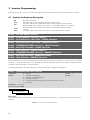
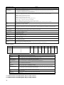
Options
0 = Inactive
1 = Disable via
Run/Stop
2 = Disable via
General Enable
3 = Change to
LOCAL
4 = Change to
LOCAL keeping
the commands
and the reference
5 = Fault Trip
Description
No action is taken and the inverter remains in
the existing status
A stop command with deceleration ramp is
executed and the motor stops according to the
programmed deceleration ramp
The inverter is disabled by removing the
General Enabling and the motor coasts to stop
The inverter commands change to LOCAL
The inverter is changed to the local mode;
However, the enabling and reference
commands received via the network , in case
the inverter had been programmed for
start/stop via HMI or 3-wire and reference via
HMI or electronic potentiometer, are kept in the
local mode.
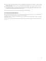
Instead of an alarm, a communication error
causes a fault at the inverter, so that it becomes
necessary to perform the inverter fault reset in
order to get it back to normal operation.
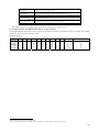
For the CAN interface used with the DeviceNet protocol, the following events are considered communication errors:
;
;
;
;
A133 Alarm/F233 fault: CAN interface without power supply.
A134 Alarm/F233 fault: bus off.
A136 Alarm/F233 fault: Idle master.
A137 Alarm/F233 fault: timeout in one or more I/O connections has occurred.
The description of these alarms/faults is presented in the section 4.
The actions described in this parameter are performed by means of the automatic writing of the respective bits on
the Control Word via CAN parameter – P0684. In order that the commands written in this parameter be executed,
it is necessary that the inverter be programmed to be commanded via DeviceNet. This programming is done by
means of parameters P0220 to P0228.
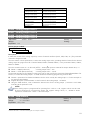
P0680 – Logical Status
0000h – FFFFh
Adjustable
Range:
Factory
Setting:
-
Proprieties: RO
Access groups via HMI:
01 PARAMETER GROUPS.
∟ 49 Communication
.
∟ 111 Status/Commands
.
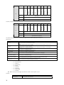
7
6
In Alarm condition
In configuration
mode
5
4
3 to 0
Reserved
8
Quick Stop
Activated
9
Second Ramp
10
Ramp enabled
LOC/REM
11
General Enabling
active
12
Speed Direction
13
JOG
14
Undervoltage
Function
15
Manual/ Automatic
Bits
Fault condition
Description:
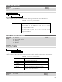
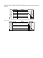
It allows the monitoring of the inverter status. Each bit corresponds to one state:
Table 3.2 - Parameter P0680 bit functions
Bits
Bits 0 to 3
Bit 4
Quick Stop Activated
Values
Reserved
0: Quick stop command is not activated.
1: Inverter is executing quick stop command.
15