1
THE UNIDEX 511 MOTION
CONTROLLER
USER’S MANUAL
P/N: EDU162 (V1.1)
AEROTECH, Inc. • 101 Zeta Drive • Pittsburgh, PA. 15238-2897 • USA
Phone (412) 963-7470 • Fax (412) 963-7459
Product Service: (412) 967-6440; (412) 967-6870 (Fax)
www.aerotechinc.com
If you should have any questions about the UNIDEX 511 Motion Controller or comments regarding the
documentation, please refer to Aerotech online at:
http://www.aerotechinc.com.
For your convenience, a product registration form is available at our web site.
Our web site is continually updated with new product information, free downloadable software and special pricing on
selected products.
The UNIDEX 511 Motion Controller is a product of Aerotech, Inc.
Borland C is a product of Borland International, Inc.
IBM PC/AT bus is a registered trademark of International Business Machines, Inc.
Inductosyn is a registered trademark of Ruhle Companies, Inc.
iSBX is a registered trademark of Intel Corporation.
MS-DOS and Windows are products of Microsoft Corporation.
Opto 22 is a product and trademark of Opto 22.
The UNIDEX 511 Motion Controller
User’s Manual Revision History:
Preliminary
Rev 1.0
Rev 1.0a
Rev 1.1
October 2, 1997
May 7, 1998
July 27,1998
June 26, 2000
U511 User’s Manual
Table of Contents
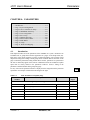
TABLE OF CONTENTS
CHAPTER 1:
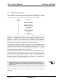
1.1.
1.2.
1.3.
1.4.
INTRODUCTION ............................................................................ 1-1
Overview of the UNIDEX 511 System............................................... 1-1
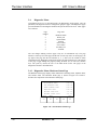
Ordering Information.......................................................................... 1-3
Options and Accessories..................................................................... 1-4
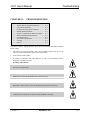
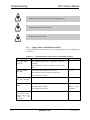
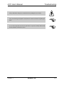
Safety Procedures and Warnings ........................................................ 1-5
CHAPTER 2:
2.1.
2.2.
2.3.
2.4.
2.5.
2.6.
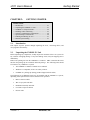
GETTING STARTED...................................................................... 2-1
Introduction ........................................................................................ 2-1
Unpacking the UNIDEX 511 Unit ..................................................... 2-1
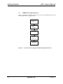
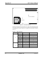
UNIDEX 511 Setup Flowchart........................................................... 2-2
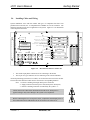
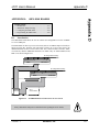
Installing Cables and Wiring .............................................................. 2-3
Software Configuration Considerations.............................................. 2-4
Special Startup Considerations ........................................................... 2-4
2.6.1. Feedback Verification .......................................................... 2-4
2.6.2. Limit Verification................................................................. 2-5
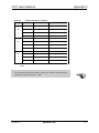
2.6.3. Preliminary Servo Loop Setup ............................................. 2-6
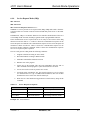
Enabling and Moving an Axis ............................................................ 2-7
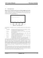
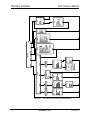
Internal System Wiring....................................................................... 2-7
2.7.
2.8.
CHAPTER 3:
3.1.
3.2.
3.3.
3.4.
3.5.
3.6.
3.7.
3.8.
Version 1.1
THE USER INTERFACE................................................................ 3-1
Introduction ........................................................................................ 3-1
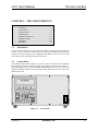
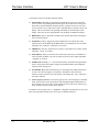
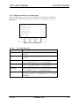
Control Panel...................................................................................... 3-1
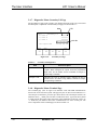
Power-up Screen................................................................................. 3-3
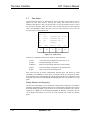
Program Menu .................................................................................... 3-5
3.4.1. Program Menu: the Run Submenu ....................................... 3-5
3.4.2. Program Menu: the Edit Submenu ....................................... 3-7
3.4.3. The ASCII Utility............................................................... 3-11
3.4.4. Program Menu: the File Submenu...................................... 3-12
3.4.5. Program Menu: The Digitize Submenu.............................. 3-12
Setup Menu: Parameters................................................................... 3-17
3.5.1. Setup Menu: The Fault Masks Page................................... 3-19
Diagnostics Menu ............................................................................. 3-20
3.6.1. Diagnostics Menu: Hardware Status Page.......................... 3-20
3.6.2. Diagnostics Menu: Primary I/O Page................................. 3-21
3.6.3. Diagnostics Menu: System Status Page.............................. 3-22
3.6.4. Diagnostics Menu: Position Page....................................... 3-23
3.6.5. Diagnostics Menu: Active Limits Page .............................. 3-24
3.6.6. Diagnostics Menu: Servo Faults Page ................................ 3-25
3.6.7. Diagnostics Menu: Secondary I/O Page............................. 3-26
3.6.8. Diagnostics Menu: Terminal Page ..................................... 3-26
Tune Menu ....................................................................................... 3-28
3.7.1. Troubleshooting Autotuning .............................................. 3-30
MDI Menu........................................................................................ 3-31
3.8.1. MDI Menu: Joystick Submenu........................................... 3-32
3.8.2. MDI Menu: Jog Submenu .................................................. 3-32
3.8.3. MDI Menu: Commands Submenu...................................... 3-33
Aerotech, Inc.
iii
Table of Contents
U511 User’s Manual
CHAPTER 4:
4.1.
4.2.
4.3.
4.4.
4.5.
iv
PARAMETERS ................................................................................ 4-1
Introduction ........................................................................................ 4-1
Page 1: System Configuration............................................................. 4-7
4.2.1. “Auto enable axes” ............................................................... 4-7
4.2.2. “Auto run program”.............................................................. 4-7
4.2.3. “Axis calibration file”........................................................... 4-7
4.2.4. “Parameter file”.................................................................... 4-7
4.2.5. “Firmware file”..................................................................... 4-7
4.2.6. “M-code file”........................................................................ 4-7
4.2.7. “Global subroutine file” ....................................................... 4-8
4.2.8. “PSO-PC firmware file” ....................................................... 4-8
4.2.9. “PSO-PC DPRAM address” (hex address 0xnnnn).............. 4-8
4.2.10. “PSO-PC I/O address” (hex address 0xnnn) ........................ 4-9
4.2.11. “Safe zone output bit 0,1-8” ................................................. 4-9
4.2.12. “Option board setup code” ................................................... 4-9
4.2.13. “User interrupt setup code” ................................................ 4-10
4.2.14. “A/D channel n joystick deadband” Parameters ................ 4-10
4.2.15. “A/D channel n center” Position Parameters...................... 4-11
4.2.16. “Enable speaker” ................................................................ 4-11
4.2.17. “Password” ......................................................................... 4-12
4.2.18. “Abort on input high 0, 1-16”............................................. 4-12
Pages 2 and 3: Serial Port #n Setup .................................................. 4-13
4.3.1. “Baud rate” (bits per second) ............................................. 4-13
4.3.2. “Data bits” (7-8) ................................................................. 4-13
4.3.3. “Stop bits” (1-2) ................................................................. 4-13
4.3.4. “Parity” (N, O, E) ............................................................... 4-13
4.3.5. “End of string character” .................................................... 4-13
4.3.6. “Fast output?” (y/n) ............................................................ 4-13
4.3.7. “Command ACK character” ............................................... 4-14
4.3.8. “Command NAK character”............................................... 4-14
4.3.9. “Default configuration” ...................................................... 4-14
Page 4: GPIB/IEEE-488 Setup ......................................................... 4-15
4.4.1. “GPIB address” (0-30) ....................................................... 4-15
4.4.2. “EOS character” ................................................................. 4-15
4.4.3. “Parallel Pol Response bit” (0-NONE or 1-8).................... 4-15
4.4.4. “Time out” (seconds).......................................................... 4-15
4.4.5. “Default configuration” ...................................................... 4-15
Page 5: Axis Configuration............................................................... 4-16
4.5.1. “Metric (x00) and English (x01) conversion factors”......... 4-16
4.5.2. “Max accel/decel” (machine steps/ms/ms) ......................... 4-19
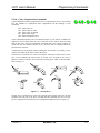
4.5.3. “Positive (+) move is CW” (y/n) ........................................ 4-19
4.5.4. “Positive (+) jog same as + move” (y/n) ............................ 4-20
4.5.5. “Enable pause in freerun” (y/n) .......................................... 4-20
4.5.6. “Enable MFO in freerun” (y/n)........................................... 4-21
4.5.7. “Enable axis calibration” (y/n) ........................................... 4-21
4.5.8. “In position deadband” (machine steps) ............................. 4-25
4.5.9. “Backlash correction amount” (machine steps) .................. 4-26
4.5.10. “Joystick high speed” (machine steps/sec) ......................... 4-27
Aerotech, Inc.
Version 1.1
U511 User’s Manual
4.6.
4.7.
4.8.
Version 1.1
Table of Contents
4.5.11. “Joystick low speed” (machine steps/sec) .......................... 4-27
4.5.12. “Joystick absolute scale” (machine steps) .......................... 4-28
4.5.13. “Enable orthogonality table” (y/n) ..................................... 4-29
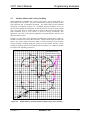
4.5.14. “Enable 2-D error mapping” (y/n)...................................... 4-29
4.5.15. “Modulo rollover” (machine steps) for axes 1-4 ................ 4-29
4.5.16. “Filter time constant” (ms) ................................................. 4-31
4.5.17. “AUX output active high” (y/n) ......................................... 4-31
4.5.18. Reverse Joystick Direction................................................. 4-31
4.5.19. “Jog low speed” ( machine steps / ms ) .............................. 4-31
4.5.20. “Jog high speed” ( machine steps / ms ) ............................. 4-31
4.5.21. “Jog distance” ( machine steps )......................................... 4-31
Page 6: Servo Loop .......................................................................... 4-32
4.6.1. “Kpos” (position loop gain, 0-8,388,607) .......................... 4-32
4.6.2. “Ki” (velocity loop integrator, 0-8,388,607) ...................... 4-32
4.6.3. “Kp” (velocity loop proportional gain, 0-8,388,607) ......... 4-32
4.6.4. “Vff” (velocity feed forward, 0-8,388,607)........................ 4-33
4.6.5. “Aff” (acceleration feed forward, 0-8,388,607) ................. 4-33
4.6.6. “Loop update rate (* 0.25 ms)” .......................................... 4-34
4.6.7. “Enable Notch Filter?” (y/n) .............................................. 4-34
4.6.8. “Notch filter N0, N1, N2, D1, and D2”.............................. 4-35
4.6.8.1.
The Notch Filter............................................ 4-35
4.6.8.2.
Notch Filter Example.................................... 4-36
4.6.8.3.
The Second Order, Low Pass Filter .............. 4-38
4.6.9. “Servo loop type”............................................................... 4-39
Page 7: Homing and Limits .............................................................. 4-41
4.7.1. The Home Cycle................................................................. 4-41
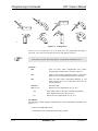
4.7.2. “Home direction CCW” (y/n)............................................. 4-42
4.7.3. “Home switch normally open” (y/n)................................... 4-43
4.7.4. “Home feedrate” (machine steps/ms) ................................. 4-44
4.7.5. “Home offset” (machine steps)........................................... 4-44
4.7.6. “Limit switch normally open” (y/n).................................... 4-45
4.7.7. “Limit to mechanical stop” (machine steps)....................... 4-45
4.7.8. “CCW software limit” (machine steps) .............................. 4-46
4.7.9. “CW software limit” (machine steps)................................. 4-46
4.7.10. “Use home limit during home” (y/n) .................................. 4-47
4.7.11. “Safe zone limits” (machine steps)..................................... 4-47
4.7.12. “Limit debounce distance” (machine steps) ....................... 4-48
Page 8: Motors and Feedback........................................................... 4-49
4.8.1. Introduction to Motor and Feedback Configurations ......... 4-50
4.8.2. “Position channel”.............................................................. 4-56
4.8.3. “Velocity channel” ............................................................. 4-57
4.8.4. “Position setup code” ......................................................... 4-58
4.8.5. “Velocity setup code”......................................................... 4-59
4.8.6. “Amplifier type” (0-DC Brush, 1-AC Brushless, 2-Step, 3Recirc)................................................................................ 4-60
4.8.7. “Commutation cycles/rev” (AC brushless motors only)..... 4-61
4.8.8. “Feedback steps/rev” (AC brushless motors only) ............. 4-62
4.8.9. “Commutation phase offset” (0-359 degrees) .................... 4-62
Aerotech, Inc.
v
Table of Contents
U511 User’s Manual
4.9.
4.10.
4.11.
vi
4.8.10. “Stepper high current %” (0-100%) (stepper drives only)......... 4-62
4.8.11. “Stepper low current %” (0-100%) (stepper drives only).......... 4-63
4.8.12. “Microstepping resolution” (machine steps) (stepper drives
only) .......................................................................................... 4-63
4.8.13. “Stepper correction” (y/n) (stepper drives only)........................ 4-63
4.8.14. “Stepper correction speed” (microsteps/ms) ............................. 4-64
4.8.15. “Base speed” (machine steps/ms) (AC brushless only) ............. 4-64
4.8.16. “Base speed advance” (0-359 degrees) (AC brushless only)..... 4-65
4.8.17. “Phase speed” (machine steps/ms) (AC brushless only)............ 4-65
4.8.18. “Phase speed advance” (0-359 degrees) (AC brushless only) ... 4-65
4.8.19. “DAC offset parameters” (mV) ................................................. 4-65
4.8.20. “Encoder factor”........................................................................ 4-66
Page 9: Fault Masks................................................................................. 4-67
4.9.1. Introduction to Fault Masks....................................................... 4-67
4.9.2. “Global fault mask”................................................................... 4-69
4.9.3. “Disable” ................................................................................... 4-69
4.9.4. “Interrupt” ................................................................................. 4-69
4.9.5. “AUX output”............................................................................ 4-69
4.9.6. “Halt queue”.............................................................................. 4-70
4.9.7. “Abort motion”.......................................................................... 4-70
4.9.8. “Enable brake” .......................................................................... 4-70
Page 10: Traps ......................................................................................... 4-71
4.10.1. “Top feedrate” (machine steps/ms) ........................................... 4-71
4.10.2. “Maximum velocity error” (0-8,388,607) ................................. 4-72
4.10.3. “Maximum position error” (0-8,388,607) ................................. 4-73
4.10.4. “Maximum integral error” (0-8,388,607) .................................. 4-74
4.10.5. “RMS current trap” (0-100%) ................................................... 4-75
4.10.6. “RMS current sample time” (1-16,383 ms) ............................... 4-77
4.10.7. “Clamp current output” (0-100%) ............................................. 4-78
4.10.8. “AUX fault output bit” (0, 1-8) ................................................. 4-79
4.10.9. “Amplifier fault active low” (y/n).............................................. 4-80
Page 11: Planes and Mapping.................................................................. 4-81
4.11.1. Overview of Planes.................................................................... 4-81
4.11.2. “Number of contour planes” (1, 2, or 4).................................... 4-84
4.11.3. “Keep position after reset?” (y/n).............................................. 4-86
4.11.4. “MFO pot offset” (0-255).......................................................... 4-87
4.11.5. “Axis {1, 2, 3, 4} plane 1-4 as X, Y, Z, U”............................... 4-88
4.11.6. “Axis {1,2,3,4} gantry yes/none slave {1,2,3,4}” ..................... 4-90
4.11.7. “Segment time” (1-20 ms) ......................................................... 4-93
4.11.8. “Ramp time” (1-32,000 ms) ...................................................... 4-94
4.11.9. “Default to metric” (yes/no) ...................................................... 4-95
4.11.10. “Linear accel/decel” (y/n).......................................................... 4-96
4.11.11. “Contour feedrate” (program steps/ms)..................................... 4-97
4.11.12. “X, Y, Z, and U axes index feedrates” (program steps/ms)....... 4-97
4.11.13. “Clamp feedrate” (program steps/ms) ....................................... 4-98
4.11.14. “Corner rounding time” (1-32,000 ms) ..................................... 4-98
4.11.15. “Metric digits” (1-8)................................................................ 4-101
4.11.16. “English digits” (1-8) .............................................................. 4-102
Aerotech, Inc.
Version 1.1
U511 User’s Manual
Table of Contents
4.11.17. “Contouring mode” .......................................................... 4-103
CHAPTER 5:
5.1.
5.2.
5.3.
5.4.
5.5.
Version 1.1
PROGRAMMING COMMANDS .................................................. 5-1
Introduction ........................................................................................ 5-1
Mathematical Function Commands .................................................... 5-2
5.2.1. Direct Variables (V0 through V255).................................... 5-2
5.2.2. Indirect Variables (VV0 through VV255)............................ 5-2
5.2.3. Functions .............................................................................. 5-3
5.2.4. Operators and Evaluation Hierarchy .................................... 5-4
System Registers................................................................................. 5-5
5.3.1. Relative Position Registers................................................... 5-5
5.3.2. Absolute Position Registers.................................................. 5-6
5.3.3. Real Time Feedback Position Registers ............................... 5-6
5.3.4. Real Time Command Position Registers.............................. 5-7
5.3.5. Understanding the Concept of Program Steps...................... 5-7
5.3.6. A/D Channel Registers ......................................................... 5-8
System Inputs $INP and $IN0-$INF .................................................. 5-8
Programming Commands ................................................................. 5-10
5.5.1. ABORT .............................................................................. 5-13
5.5.2. ACCELERATION ............................................................. 5-13
5.5.3. AC PL (ACCEL PLANE) .................................................. 5-14
5.5.4. AFCO (Auto Focus) ........................................................... 5-15
5.5.5. AGAIN............................................................................... 5-18
5.5.6. AT (Autotune) .................................................................... 5-19
5.5.7. BEEP.................................................................................. 5-20
5.5.8. BOARD.............................................................................. 5-20
5.5.9. BRAKE .............................................................................. 5-21
5.5.10. CAL (Load Calibration File) .............................................. 5-22
5.5.11. CLOCKWISE and COUNTERCLOCKWISE CIRCULAR
INTERPOLATION ............................................................ 5-22
5.5.12. CLRSCR (Clear Screen) .................................................... 5-26
5.5.13. CI (Command Interrupt)..................................................... 5-26
5.5.14. CM (Contouring Mode) ..................................................... 5-27
5.5.15. COMREC (Strings In Port) ................................................ 5-28
5.5.16. COMVAR (String to Variable) .......................................... 5-29
5.5.17. CS (Command Scope) ........................................................ 5-30
5.5.18. Cutter Compensation Commands ....................................... 5-31
5.5.19. CVI (Convert to Integer) .................................................... 5-34
5.5.20. CYCLE............................................................................... 5-34
5.5.21. DAC (D/A Output)............................................................. 5-35
5.5.22. DISABLE........................................................................... 5-36
5.5.23. DS (Display Servo Loop Data) .......................................... 5-37
5.5.24. DWELL.............................................................................. 5-38
5.5.25. DY (Dynamic Gain) ........................................................... 5-38
5.5.26. ENABLE ............................................................................ 5-39
5.5.27. ERROR .............................................................................. 5-40
Aerotech, Inc.
vii
Table of Contents
U511 User’s Manual
5.5.28.
5.5.29.
5.5.30.
5.5.31.
5.5.32.
5.5.33.
5.5.34.
5.5.35.
5.5.36.
5.5.37.
5.5.38.
5.5.39.
5.5.40.
5.5.41.
5.5.42.
5.5.43.
5.5.44.
5.5.45.
5.5.46.
5.5.47.
5.5.48.
5.5.49.
5.5.50.
5.5.51.
5.5.52.
5.5.53.
5.5.54.
5.5.55.
5.5.56.
5.5.57.
5.5.58.
5.5.59.
5.5.60.
5.5.61.
5.5.62.
5.5.63.
5.5.64.
5.5.65.
5.5.66.
5.5.67.
5.5.68.
5.5.69.
5.5.70.
5.5.71.
5.5.72.
5.5.73.
5.5.74.
5.5.75.
viii
EXIT................................................................................... 5-41
FAULT ACKNOWLEDGE ............................................... 5-42
FL (Filter Time Constant) .................................................. 5-42
FREERUN.......................................................................... 5-43
GAIN.................................................................................. 5-44
GEAR................................................................................. 5-45
GOTO................................................................................. 5-46
HALT ................................................................................. 5-47
HOME ................................................................................ 5-48
IF ........................................................................................ 5-48
INDEX ............................................................................... 5-50
INn (Read Inputs)............................................................... 5-51
INTERRUPT...................................................................... 5-52
IO (Set/Read 8 X 3 I/O) ..................................................... 5-52
IOSET (Setup 8 X 3 I/O).................................................... 5-53
JOG .................................................................................... 5-54
Label Marker (:) ................................................................. 5-54
LINEAR ............................................................................. 5-55
LOOP ................................................................................. 5-56
LVDT ................................................................................. 5-57
M0 (M Zero) ...................................................................... 5-58
MAP ................................................................................... 5-58
MCOMM (Motor Commutation) ....................................... 5-59
MESSAGE ......................................................................... 5-60
MR (Memory Read) ........................................................... 5-61
MSET (Motor Setup) ......................................................... 5-62
MW (Memory Write) ......................................................... 5-64
NEXT ................................................................................. 5-65
OEn (Extended Output)...................................................... 5-65
OUTPUT............................................................................ 5-66
PARALLEL........................................................................ 5-67
PRM (PARAMETER READ) ........................................... 5-67
PAUSE ............................................................................... 5-68
PLANE............................................................................... 5-69
PROGRAM ........................................................................ 5-70
QUEUE .............................................................................. 5-72
RAMP ................................................................................ 5-74
REFERENCE ..................................................................... 5-75
RETURN............................................................................ 5-75
ROTATE (Part Rotation) ................................................... 5-75
ROUNDING....................................................................... 5-76
SCF (Overriding Scale Factor) ........................................... 5-77
SEGMENT......................................................................... 5-79
SKEY (Soft Keys) .............................................................. 5-80
SLEW................................................................................. 5-81
SOFTWARE ...................................................................... 5-83
SPLINE .............................................................................. 5-84
START ............................................................................... 5-85
Aerotech, Inc.
Version 1.1
U511 User’s Manual
Table of Contents
5.5.76.
5.5.77.
5.5.78.
5.5.79.
5.5.80.
5.5.81.
5.5.82.
5.5.83.
SUBROUTINE .................................................................. 5-86
SYNC ................................................................................. 5-87
Target Tracking Commands (TE, TD, TP) ........................ 5-87
TRAJECTORY .................................................................. 5-88
TRIGGER .......................................................................... 5-89
UMFO (Manual Feed Override)......................................... 5-90
VAR (Read/Write Variables) ............................................. 5-91
VELOCITY........................................................................ 5-92
5.5.83.1.
Correct Usage and Limitations of the Velocity
Profiling Algorithm....................................... 5-93
5.5.83.2.
CM1 Contouring Mode................................. 5-96
5.5.84. WAIT ............................................................................... 5-100
5.5.85. WHILE/ENDWHILE....................................................... 5-101
CHAPTER 6:
6.1.
6.2.
6.3.
6.4.
6.5.
6.6.
Version 1.1
REMOTE MODE OPERATIONS.................................................. 6-1
Introduction ........................................................................................ 6-1
6.1.1. GPIB IEEE-488 Interface .................................................... 6-1
6.1.2. RS-232 (COM1 and COM2) Interface ................................. 6-1
Troubleshooting Remote Communications......................................... 6-2
Command Handshake Mode (RS-232 Only) ...................................... 6-2
Remote Commands............................................................................. 6-2
6.4.1. ##: Enable RS-232 Remote Communications ...................... 6-2
6.4.2. Program Execution............................................................... 6-3
6.4.3. PA: Program Abort .............................................................. 6-4
6.4.4. Service Request Mode (SRQ) .............................................. 6-5
6.4.5. Hold/Trigger/Cancel ............................................................ 6-7
6.4.6. PE: Print Error Message String ............................................ 6-8
6.4.7. I: Execute Immediate Command .......................................... 6-9
6.4.8. FMn: Format of Returned Data .......................................... 6-10
6.4.9. PXn, PYn, PZn, PUn: Axis Positions................................. 6-11
6.4.10. Q: Serial Pol command ...................................................... 6-12
6.4.11. PSn: Print Status................................................................. 6-13
6.4.12. RRn/WRn,val: Read / Write Register................................ 6-16
6.4.13. Parameter Editing............................................................... 6-18
6.4.14. RE: Hardware Reset ........................................................... 6-19
6.4.15. File Transfers ..................................................................... 6-20
6.4.16. PD: Print Directory ............................................................ 6-22
6.4.17. PPfile: Print Program “File” to Port ................................... 6-23
6.4.18. RVn: Read Variable ........................................................... 6-23
6.4.19. DFfilename: Delete File ..................................................... 6-24
6.4.20. HE [cmd]: Help Menu........................................................ 6-24
6.4.21. GV: Software Version ........................................................ 6-25
UNIDEX 511 Remote Timing.......................................................... 6-26
C Program Example.......................................................................... 6-27
Aerotech, Inc.
ix
Table of Contents
U511 User’s Manual
CHAPTER 7:
7.1.
7.2.
7.3.
7.4.
7.5.
7.6.
WINDOWS INTERFACE AND UTILITIES................................. 7-1
Introduction ........................................................................................ 7-1
COM Port Settings: Common to all Software Utilities ....................... 7-1
UNIDEX 511 Parameter Editor.......................................................... 7-2
7.3.1. Edit Parameters: The Number, Value, and Axis Fields ........ 7-4
UNIDEX 511 Axis Scope Utility ....................................................... 7-5
UNIDEX 511 Diagnostics Screen ...................................................... 7-5
UNIDEX 511 File Transfer Utility..................................................... 7-9
7.6.1. Manufacturing Mode ............................................................ 7-9
7.6.2. Loading System Software..................................................... 7-9
7.6.3. Loading DOS or BIOS ....................................................... 7-10
7.6.4. Erasing B Drive.................................................................. 7-10
7.6.5. Uploading a File (to UNIDEX 511) ................................... 7-10
7.6.6. Downloading a file (from UNIDEX 511)........................... 7-11
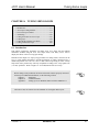
CHAPTER 8: TUNING SERVO LOOPS ............................................................... 8-1
8.1.
Introduction ........................................................................................ 8-1
8.2.
Axis Scope Tuning Window............................................................... 8-3
8.2.1. The File Menu ...................................................................... 8-4
8.2.2. The Remote Menu ................................................................ 8-4
8.2.3. The Plot Menu...................................................................... 8-5
8.2.4. The Trigger Menu ................................................................ 8-5
8.2.5. The Collect Menu................................................................. 8-6
8.2.6. The Display Menu ................................................................ 8-6
8.2.7. The Axis Menu..................................................................... 8-7
8.2.8. The Units Menu.................................................................... 8-7
8.2.9. The Tools Menu ................................................................... 8-7
8.3.
The Axis Scope Toolbars ................................................................... 8-8
8.3.1. “Kp” Proportional Gain........................................................ 8-9
8.3.2. “Ki” Integral Gain ................................................................ 8-9
8.3.3. “Kpos” Position Gain ........................................................... 8-9
8.3.4. “Vff” Velocity Feedforward Gain ........................................ 8-9
8.3.5. “Aff” Acceleration Feedforward Gain.................................. 8-9
8.4.
Autotuning ........................................................................................ 8-10
8.4.1. Setting up an Excitation...................................................... 8-10
8.4.2. Specifying Desired Performance ........................................ 8-10
8.4.3. Bandwidth and Damping .................................................... 8-10
8.4.4. Autotuning Procedure......................................................... 8-11
8.4.5. Dual Loop Systems............................................................. 8-14
8.4.6. Guidelines and Limitations................................................. 8-14
8.4.7. Troubleshooting Autotuning............................................... 8-15
8.5.
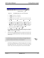
Tuning Procedure for Servo Loops................................................... 8-16
8.6.
Tuning Tips ...................................................................................... 8-24
8.7.
Tuning With Tachometer Feedback.................................................. 8-25
8.7.1. In-Position Integrator ......................................................... 8-25
8.7.2. Velocity Feed Forward ....................................................... 8-25
8.7.3. Servo Parameter Setup for Tachometer Feedback.............. 8-26
8.7.4. The Axis Scope Toolbars ................................................... 8-26
x
Aerotech, Inc.
Version 1.1
U511 User’s Manual
8.8.
CHAPTER 9:
9.1.
9.2.
9.3.
9.4.
9.5.
9.6.
9.7.
9.8.
9.9.
9.10.
9.11.
9.12.
9.13.
9.14.
Table of Contents
8.7.4.1.
“Kpos” Position Gain.................................... 8-26
8.7.4.2.
“Ki” In-Position Integrator ........................... 8-26
8.7.4.3.
“Vff” Velocity Feedforward Gain................. 8-27
8.7.4.4.
“Kp” Proportional Gain ................................ 8-27
8.7.4.5.
“Aff” Acceleration Feedforward Gain .......... 8-27
Tuning Tachometer Loops................................................................ 8-28
PROGRAMMING EXAMPLES..................................................... 9-1
Introduction ........................................................................................ 9-1
Incremental (Relative) Motion with Velocity Profiling ...................... 9-2
Absolute Motion with Velocity Profiling ........................................... 9-5
CNC Demonstration Using Velocity Profiling, Linear, and Circular
Interpolation ....................................................................................... 9-7
Corner Rounding ................................................................................ 9-8
GEAR Demonstration of a Master Axis with Two Slave Axes ........ 9-10
Interlocking Contour Planes ............................................................. 9-11
Splining ............................................................................................ 9-12
Programming Using Inputs............................................................... 9-13
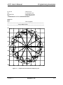
Part Rotation..................................................................................... 9-14
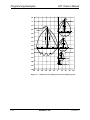
Overriding Scale Factor.................................................................... 9-16
Softkey Use ...................................................................................... 9-19
8 X 3 I/O Bus Program..................................................................... 9-20
Power on Subroutine/Global Subroutine File ................................... 9-21
CHAPTER 10: TECHNICAL DETAILS................................................................ 10-1
10.1.
UNIDEX 511 Rear Panel Connectors .............................................. 10-1
10.1.1. Axis Connectors (Encoder Input)....................................... 10-1
10.1.2. Serial Port Connections...................................................... 10-3
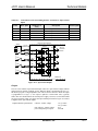
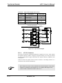
10.1.3. Interfacing to the U511 Digital I/O .................................... 10-4
10.1.3.1.
16 IN/8 OUT I/O Bus ................................... 10-4
10.1.3.2.
Opto 22 Connection Information .................. 10-5
10.1.3.3.
8 X 3 I/O Bus................................................ 10-9
10.1.3.4.
On-board Opto-isolated I/O ........................ 10-10
10.1.4. AUX I/O Connector ......................................................... 10-12
10.1.4.1.
UINT User Interrupt Input.......................... 10-14
10.1.4.2.
E-Stop Emergency Stop Input..................... 10-14
10.1.5. Joystick Connector ........................................................... 10-15
10.1.6. IEEE-488 / GPIB Bus Connector..................................... 10-16
10.1.7. Axis 1-4 Motor Connectors.............................................. 10-16
10.2.
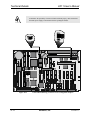
Control Board Jumpers................................................................... 10-17
10.3.
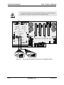
Interface Board Jumpers................................................................. 10-19
10.4.
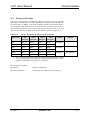
Encoder Specifications ................................................................... 10-21
10.5.
UNIDEX 511 Control Board Test Points (TP1-TP25)................... 10-22
10.6.
“PSO Encoder Bus” Connector (P6) .............................................. 10-23
10.7.
UNIDEX 511 Mechanical Specifications....................................... 10-24
10.7.1. UNIDEX 511 Desktop Specifications.............................. 10-24
10.7.2. UNIDEX 511 Rack mount Specifications........................ 10-24
10.8.
UNIDEX 511 Electrical Specifications .......................................... 10-25
10.9.
UNIDEX 511 Environmental Specifications.................................. 10-26
Version 1.1
Aerotech, Inc.
xi
Table of Contents
CHAPTER 11:
11.1.
11.2.
11.3.
11.4.
11.5.
11.6.
11.7.
11.8.
11.9.
11.10.
U511 User’s Manual
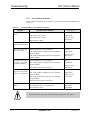
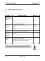
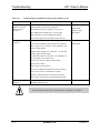
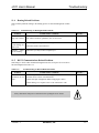
TROUBLESHOOTING ................................................................. 11-1
Stepper Motors and Related Problems.............................................. 11-2
Servo Related Problems.................................................................... 11-4
Problems Involving Fault Conditions ............................................... 11-5
Homing Related Problems ................................................................ 11-7
RS-232 Communications Related Problems ..................................... 11-7
IEEE-488/GPIB Related Problems................................................... 11-8
Fuse Replacement............................................................................. 11-8
Preventative Maintenance................................................................. 11-9
Cleaning............................................................................................ 11-9
Battery .............................................................................................. 11-9
APPENDIX A: GLOSSARY OF TERMS................................................................ A-1
APPENDIX B: WARRANTY AND FIELD SERVICE .......................................... B-1
APPENDIX C: SETTING UP AN AC BRUSHLESS MOTOR WITH THE
UNIDEX 511 .....................................................................................C-1
C.1.
Introduction ........................................................................................C-1
C.2.
Setup Procedure..................................................................................C-1
APPENDIX D:
D.1.
D.2.
D.3.
D.4.
iSBX-IO48 BOARDS........................................................................D-1
Introduction ....................................................................................... D-1
iSBX-IO48 Jumper Settings .............................................................. D-5
Configuring the iSBX-IO48............................................................... D-5
Programming the iSBX-IO48 ............................................................ D-6
APPENDIX E:
E.1.
E.2.
E.3.
BACKUP UTILITY..........................................................................E-1
Introduction ........................................................................................E-1
Memory Banks....................................................................................E-1
Backing-up Files.................................................................................E-1
APPENDIX F:
F.1.
F.2.
F.3.
UNIDEX 11 EMULATION SOFTWARE...................................... F-1
Introduction ........................................................................................ F-1
Supported Commands......................................................................... F-1
Differences Between the U511 and the U11....................................... F-4
APPENDIX G:
G.1.
G.2.
G.3.
G.4.
G.5.
G.6.
G.7.
G.8.
THE RDP-PC RESOLVER-TO-DIGITAL BOARD ................... G-1
Introduction ....................................................................................... G-1
RDP Board Hardware Setup.............................................................. G-1
Installing the RDP Board into the UNIDEX 511............................... G-6
UNIDEX 511 Software Setup............................................................ G-7
Connecting the Device to the RDP Board ......................................... G-8
Adjusting the Gain on the RDP Board............................................. G-10
Nulling the Phase Offset (Rotary Inductosyns Only)....................... G-11
Verifying Resolver or Inductosyn Operation ................................... G-12
INDEX
∇ ∇ ∇
xii
Aerotech, Inc.
Version 1.1
U511 User’s Manual
List of Figures
LIST OF FIGURES
Figure 1-1.
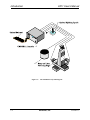
Figure 1-2.
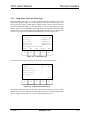
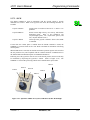
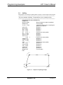
UNIDEX 511...................................................................................... 1-1
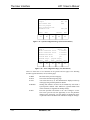
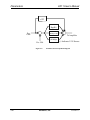
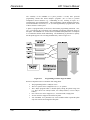
The UNIDEX 511 System Diagram ................................................... 1-2
Figure 2-1.
Figure 2-2.
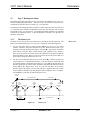
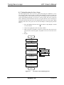
Flowchart Overviewing the Installation/Configuration Process ......... 2-2
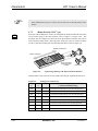
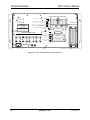
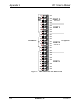
Rear Panel Connectors of the U511.................................................... 2-3
Figure 3-1.
Figure 3-2.
Figure 3-3.
Figure 3-4.
Figure 3-5.
Figure 3-6.
Figure 3-7.
Figure 3-8.
Figure 3-9.
Figure 3-10.
Figure 3-11.
Figure 3-12.
Figure 3-13.
Figure 3-14.
Figure 3-15.
Figure 3-16.
Figure 3-17.
Figure 3-18.
Figure 3-19.
Figure 3-20.
Figure 3-21.
Figure 3-22.
Figure 3-23.
Figure 3-24.
Figure 3-25.
Figure 3-26.
Figure 3-27.
Figure 3-28.
Figure 3-29.
Figure 3-30.
Figure 3-31.
Figure 3-32.
Figure 3-33.
Figure 3-34.
Control Panel...................................................................................... 3-1
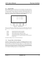
Power-Up Screen................................................................................ 3-3
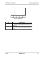
U511 Menus Activated by the Function Keys .................................... 3-4
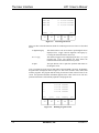
Program Screen .................................................................................. 3-5
Load Program Screen ......................................................................... 3-6
Running Program Screen.................................................................... 3-6
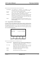
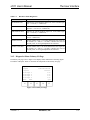
Edit File Screen, Edit File Submenu................................................... 3-7
Program Editor Screen ....................................................................... 3-8
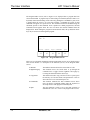
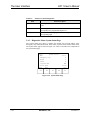
Edit Command Screen ........................................................................ 3-9
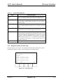
Specialized Command Edit Screen................................................... 3-10
“Save File As:” Screen ..................................................................... 3-10
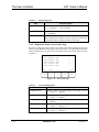
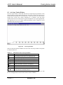
The ASCII Utility ............................................................................. 3-11
File Operations Screen ..................................................................... 3-12
Program Editor Screen, Digitize Menu............................................. 3-13
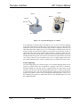
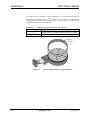
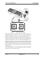
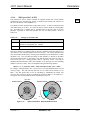
Joysticks Showing the “C” Button.................................................... 3-14
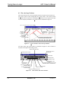
Linear Digitizing Screen................................................................... 3-15
Circular Digitizing Screen ................................................................ 3-15
Spline Command Screen................................................................... 3-16
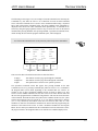
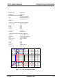
System Configuration Page (General Parameters)............................ 3-18
Axis Configuration Page (Axis Parameters) ..................................... 3-18
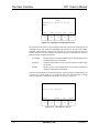
Fault Masks Page.............................................................................. 3-19
Expanded Fault Masks Page............................................................. 3-19
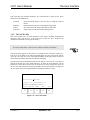
The Hardware Status Page................................................................ 3-20
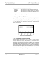
Primary I/O Page .............................................................................. 3-21
System Status Page ........................................................................... 3-22
The Position Page............................................................................. 3-23
Active Limit Page............................................................................. 3-24
Servo Faults Page ............................................................................. 3-25
Secondary I/O Page .......................................................................... 3-26
Terminal Page................................................................................... 3-27
Tune Screen...................................................................................... 3-28
MDI Screen ...................................................................................... 3-31
JStick Screen .................................................................................... 3-32
Jog Screen ........................................................................................ 3-32
Figure 4-1.
Figure 4-2.
Figure 4-3.
Figure 4-4.
Figure 4-5.
Sample ASCII Calibration File......................................................... 4-22
Sample Calibration File with Orthogonality Data............................. 4-24
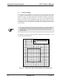
Modulo Rollover in Rotary Stage Application ................................. 4-30
Parallel Control Loop Block Diagram.............................................. 4-40
Home Cycle ...................................................................................... 4-41
Version 1.1
Aerotech, Inc.
xiii
List of Figures
U511 User’s Manual
Figure 4-6.
Figure 4-7.
Figure 4-8.
Figure 4-9.
Figure 4-10.
Figure 4-11.
Figure 4-12.
Figure 4-13.
Figure 4-14.
Figure 4-15.
Figure 4-16.
Figure 4-17.
Figure 4-18.
Figure 4-19.
Figure 5-1.
Figure 5-2.
Figure 5-3.
Figure 5-4.
Figure 5-5.
Figure 5-6.
Figure 5-7.
Figure 5-8.
Figure 5-9.
Figure 5-10.
Figure 5-11.
Figure 5-12.
Figure 5-13.
Figure 5-14.
Figure 5-15.
Figure 5-16.
Figure 5-17.
Figure 5-18.
Figure 5-19.
Figure 5-20.
Figure 5-21.
xiv
Typical Stage Showing CW and CCW Motor Rotation ................... 4-42
Motor and Encoder Rotation ............................................................ 4-51
Phase Advance Slope........................................................................ 4-64
Sample RMS Current Maximums..................................................... 4-75
Programming Control Using a Single Plane ..................................... 4-81
Programming Control Using Four Planes ......................................... 4-82
Sample Programming Segment Showing the Use of Planes ............. 4-83
MFO Potentiometer With and Without Offsets ................................ 4-87
Using “Home offset” Parameter to Keep Gantry Aligned After
Homing ............................................................................................. 4-92
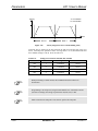
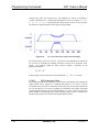
Contour Ramping (Acceleration/Deceleration) Time ....................... 4-94
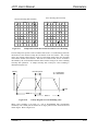
Graphs of Linear and Inverse Sine Ramping Trajectories ................ 4-96
Sample Motion Path Shown with and without Corner
Rounding .......................................................................................... 4-99
Velocity Diagram of Corner Rounding (G23) .................................. 4-99
Velocity Diagram of Non-corner Rounding (G24) ......................... 4-100
Startup Moves................................................................................... 5-31
Ending Moves................................................................................... 5-32
Cutter Compensation Example ......................................................... 5-33
CYCLE START Function ................................................................ 5-35
Sample Uses of the GOTO Command .............................................. 5-47
LVDT Sensor.................................................................................... 5-57
PAUSE Function .............................................................................. 5-68
Illustration of No Corner Rounding (G24) ....................................... 5-76
Illustration of Corner Rounding (G23) ............................................. 5-76
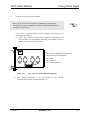
Optional UNIDEX 511 Joystick, JI Model Left, JBV Model
Right ................................................................................................. 5-81
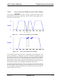
Plot of Velocity Without Velocity Profiling ..................................... 5-93
Plot of Velocity With Velocity Profiling .......................................... 5-93
Short Middle Move With No Velocity Profiling .............................. 5-94
Short Middle Move With Velocity Profiling .................................... 5-94
Same Motion With Ramping Time Reduced .................................... 5-95
Circular Profiling With Long Ramp Time ........................................ 5-95
Circular Profiling With Short Ramp Time........................................ 5-95
Two Axis Linear Move With Velocity Profiling .............................. 5-96
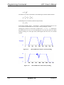
Velocity Profile for Nontangential Vectors ...................................... 5-97
Velocity Profile With Digital Filter .................................................. 5-98
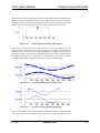
Velocity Profile Without a G9 Command at the End of the
Sequence........................................................................................... 5-99
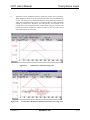
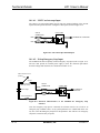
Figure 6-1.
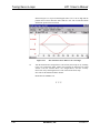
Figure 6-2.
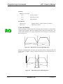
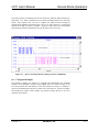
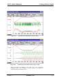
Plot Showing Signals Generated by a GPIB Command.................... 6-26
Receive and Transmit Lines During Transfer at 9600 Baud............. 6-27
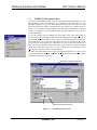
Figure 7-1.
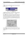
Figure 7-2.
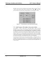
Figure 7-3.
Figure 7-4.
The Edit Parameter Screen ................................................................. 7-2
The Cascaded Transfer Menu............................................................. 7-3
Transfer Parameter Values Between Axes Popup .............................. 7-3
Transfer Parameter Values Between Planes Popup ............................ 7-4
Aerotech, Inc.
Version 1.1
U511 User’s Manual
List of Figures
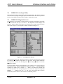
Figure 7-5.
The Diagnostics Window ................................................................... 7-5
Figure 8-1.
Figure 8-2.
Figure 8-3.
Figure 8-4.
Figure 8-5.
Figure 8-6.
Figure 8-7.
Figure 8-8.
Figure 8-9.
Figure 8-10.
Figure 8-11.
Figure 8-12.
Figure 8-13.
Figure 8-14.
Figure 8-15.
Figure 8-16.
Figure 8-17.
Figure 8-18.
Figure 8-19.
Figure 8-20.
Figure 8-21.
Figure 8-22.
Figure 8-23.
Figure 8-24.
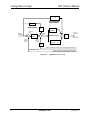
Figure 8-25.
UNIDEX 511 Servo Loop .................................................................. 8-2
Axis Scope Window ........................................................................... 8-3
Cursors Toolbar of the Axis Scope Window ...................................... 8-8
Gains, Status, and Control Toolbars ................................................... 8-8
The Gain and Auto Tune Toolbars ................................................... 8-11
Autotune Plot Where “Dist” Has Been Set Too Low ....................... 8-13
Autotune Plot Where “Dist” Has Been Set Too High ...................... 8-13
Autotune Plot Showing Proper Calibration ...................................... 8-14
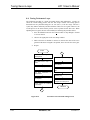
Flowchart of Overall Tuning Process ............................................... 8-16
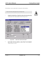
The Faults Tab of the Parameter Editor............................................ 8-17
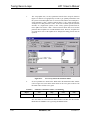
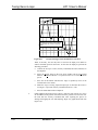
Servo Loop Tab of the Parameter Editor.......................................... 8-18
MAXIMIZE Button on the Axis Scope Window ............................. 8-19
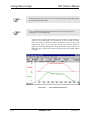
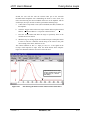
Unacceptable Velocity Error ............................................................ 8-20
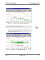
Acceptable Velocity Error (When Adjusting “Kp”) ......................... 8-21
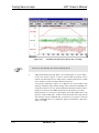
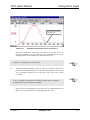
Proper Adjustment of “KI”............................................................... 8-21
Oscillation in Position Error When “Ki” is too High........................ 8-22
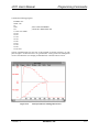
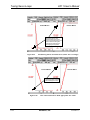
Plot Showing an Appropriate Value for “Kpos”............................... 8-23
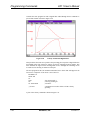
Plot Showing Overall Effects When “Kpos” is High........................ 8-23
Flowchart of Overall Tach Tuning Process ...................................... 8-28
Faults Tab of the Parameter Editor................................................... 8-29
Servo Loop Tab of the Parameter Editor.......................................... 8-30
Cross-section of the DS16020/16030 Amplifier............................... 8-31
Amplifier Potentiometer Layout ....................................................... 8-32
Axis Scope Window Showing “Kpos” Too Low.............................. 8-33
Plot Showing a Roughly Tuned Axis (When Adjusting
“Kpos”)............................................................................................. 8-34
Plot Showing the Removal of DC Offsets in the Position Error ....... 8-35
O-scope Showing Current Feedback for One Move ......................... 8-36
Plot Illustrating Smoothness in the Position Error............................ 8-37
Plot Showing Effects on Position Error (When “Ki” is too
High)................................................................................................. 8-38
Plot of the Position Error With Appropriate “Ki” Value.................. 8-38
Position Error After Increasing “Vff”............................................... 8-39
Position Error Reduced to Within 10 Counts of Error Using
“Vff”................................................................................................. 8-39
Plot of Position Error When “Vff” is too High................................. 8-40
Figure 8-26.
Figure 8-27.
Figure 8-28.
Figure 8-29.
Figure 8-30.
Figure 8-31.
Figure 8-32.
Figure 8-33.
Figure 9-1.
Figure 9-2.
Figure 9-3.
Figure 9-4.
Figure 9-5.
Figure 9-6.
Version 1.1
Sample Path for Incremental (Relative) Motion Demonstration
Using Velocity Profiling..................................................................... 9-2
Sample Path for Absolute Motion Example Using Velocity
Profiling.............................................................................................. 9-5
Sample Path of Square With and Without the Rounding
Feature................................................................................................ 9-8
Output from Splining Example......................................................... 9-12
Output from Parts Rotation Example Program ................................. 9-15
Output from Overriding Scale Factor Example Program.................. 9-18
Aerotech, Inc.
xv
List of Figures
U511 User’s Manual
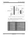
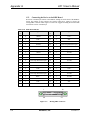
Figure 10-1.
Figure 10-10.
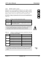
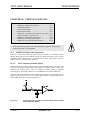
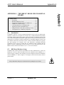
Typical Input for CW Limit, CCW Limit, Home Limit, and
Hall Effect Inputs HA, HB, HC ........................................................ 10-1
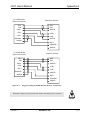
Rear View Showing Various Connectors.......................................... 10-2
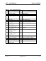
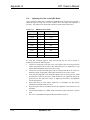
Electrical Characteristics of the UNIDEX 511 Opto 22
Connections ...................................................................................... 10-8
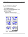
Opto-isolated Inputs ....................................................................... 10-11
Opto-isolated Outputs..................................................................... 10-12
The UINT Opto-isolated Input ....................................................... 10-14
Electrical Characteristics of the UNIDEX 511 Emergency
Stop Interface................................................................................. 10-14
Control Board Showing Locations of User Configurable
Jumpers........................................................................................... 10-18
Interface Board Showing Locations of User Configurable
Jumpers........................................................................................... 10-20
Electrical Characteristics of a Single Ended Encoder Interface...... 10-22
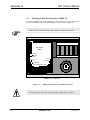
Figure C-1.
Page 7-U511 Diagnostics Window.....................................................C-3
Figure D-1.
Figure D-2.
Figure D-3.
An iSBX-IO48 Card Connected to Two I/O Cards ........................... D-1
The iSBX-IO48 Card......................................................................... D-2
iSBX-IO48 Pinouts on the PB24 I/O Card ........................................ D-4
Figure G-1.
Figure G-2.
Figure G-3.
Figure G-4.
Figure G-5.
RDP-PC Board .................................................................................. G-2
RDP Board Connection to UNIDEX 511 Board ............................... G-6
Mating DB37 Connector.................................................................... G-8
Suggested Cabling from RDP Board to Resolver or Inductosyn ....... G-9
Rectified Signals with the Most Ideal Signal ................................... G-11
Figure 10-2.
Figure 10-3.
Figure 10-4.
Figure 10-5.
Figure 10-6.
Figure 10-7.
Figure 10-8.
Figure 10-9.
∇ ∇ ∇
xvi
Aerotech, Inc.
Version 1.1
U511 User’s Manual
List of Tables
LIST OF TABLES
Table 1-1.
Table 1-2.
Table 1-3.
Basic Motion Controllers ................................................................... 1-3
Available Motor Drivers compatible with UNIDEX 511 ................... 1-4
Options and Accessories Available for the UNIDEX 511.................. 1-4
Table 2-1.
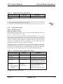
Servo Loop Tuning Parameters .......................................................... 2-6
Table 3-1.
Table 3-2.
Table 3-3.
Table 3-4.
Table 3-5.
Table 3-6.
Table 3-7.
Table 3-8.
Table 3-9.
Hardware Status Diagnostics ............................................................ 3-21
Primary I/O Status Diagnostics......................................................... 3-22
System Status Diagnostics ................................................................ 3-23
Position Diagnostics ......................................................................... 3-24
Active Limit Diagnostics .................................................................. 3-24
Servo Fault Diagnostics.................................................................... 3-25
Secondary I/O Diagnostics ............................................................... 3-26
Active Components of the Terminal Page ........................................ 3-27
Troubleshooting the Autotune Process ............................................. 3-30
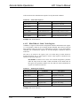
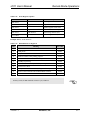
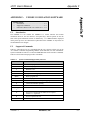
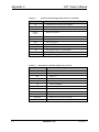
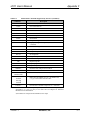
Table 4-1.
Table 4-2.
Table 4-3.
Table 4-4.
Table 4-5.
Table 4-6.
Table 4-7.
Table 4-8.
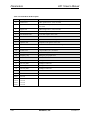
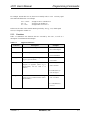
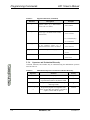
U511 Parameters Grouped by Page.................................................... 4-1
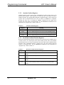
Settings for Parameter 099 ................................................................. 4-9
Settings for Parameter 500 ............................................................... 4-10
Joystick Deadband Parameters ......................................................... 4-10
Joystick Center Position Parameters................................................. 4-11
Settings for Parameter 648 ............................................................... 4-12
Settings for Parameter 501 ............................................................... 4-12
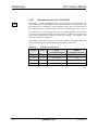
Relationship Between Number of Decimal Digits Parameters and
the Number of Programming Steps per Programming Unit.............. 4-17
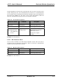
Settings for Parameter x16 ............................................................... 4-19
Settings for Parameter x11 ............................................................... 4-19
Settings for Parameter x12 ............................................................... 4-20
Settings for Parameter x13 ............................................................... 4-20
Settings for Parameter x14 ............................................................... 4-21
Settings for Parameter x15 ............................................................... 4-22
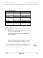
Sample Calibration Table ................................................................. 4-23
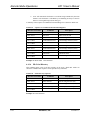
Settings for Parameter x35 ............................................................... 4-25
Settings for Parameter x37 ............................................................... 4-26
Settings for Parameter x50 ............................................................... 4-27
Settings for Parameter x51 ............................................................... 4-27
Settings for Parameter x52 ............................................................... 4-28
Settings for Parameter x71 ............................................................... 4-29
Settings for Parameters 011, 012, 013, and 014 ............................... 4-30
Settings for parameter x83................................................................ 4-31
Settings for Parameter x84 ............................................................... 4-31
Settings for Parameter x62 ............................................................... 4-34
Settings for Parameter x24 ............................................................... 4-34
Bits of Parameter x78 and PID Loop Configuration ........................ 4-39
Decimal Settings for Parameter x78 ................................................. 4-39
Settings for Parameter x02 ............................................................... 4-42
Table 4-9.
Table 4-10.
Table 4-11.
Table 4-12.
Table 4-13.
Table 4-14.
Table 4-15.
Table 4-16.
Table 4-17.
Table 4-18.
Table 4-19.
Table 4-20.
Table 4-21.
Table 4-22.
Table 4-23.
Table 4-24.
Table 4-25.
Table 4-26.
Table 4-27.
Table 4-28.
Table 4-29.
Version 1.1
Aerotech, Inc.
xvii
List of Tables
U500 User’s Manual
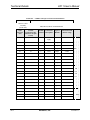
Table 4-30.
Table 4-31.
Table 4-32.
Table 4-33.
Table 4-34.
Table 4-35.
Table 4-36.
Table 4-37.
Table 4-38.
Table 4-39.
Table 4-40.
Table 4-41.
Table 4-42.
Table 4-43.
Table 4-44.
Table 4-45.
Table 4-46.
Table 4-47.
Table 4-48.
Table 4-49.
Table 4-50.
Table 4-51.
Table 4-52.
Table 4-53.
Table 4-54.
Table 4-55.
Table 4-56.
Table 4-57.
Table 4-58.
Table 4-59.
Table 4-60.
Table 4-61.
Table 4-62.
Table 4-63.
Table 4-64.
Table 4-65.
Table 4-66.
Table 4-67.
Table 4-68.
Table 4-69.
Table 4-70.
Table 4-71.
Table 4-72.
Table 4-73.
Table 4-74.
Table 4-75.
Table 4-76.
xviii
Settings for Parameter x03................................................................ 4-43
Settings for Parameter x05................................................................ 4-44
Settings for Parameter x06................................................................ 4-44
Settings for Parameter x09................................................................ 4-45
Settings for Parameter x22................................................................ 4-46
Settings for Parameter x23................................................................ 4-46
Settings for Parameter x74................................................................ 4-47
Safe Zone Limit Parameters.............................................................. 4-47
Settings for Parameter x77................................................................ 4-48
Motor Feedback Parameters ............................................................. 4-49
Commutation Factors for 4, 6, and 8 Poles....................................... 4-53
Factory Configuration for UNIDEX 511 RDP ................................. 4-54
RDP Resolution and Setup Codes .................................................... 4-55
Settings for Parameter x38................................................................ 4-56
Settings for Parameter x39................................................................ 4-57
Settings for Parameter x40................................................................ 4-58
Settings for Parameter x41................................................................ 4-59
Settings for Parameter x42................................................................ 4-60
Sample Commutation Factors for AC Brushless Motors .................. 4-61
Settings for Parameter x64................................................................ 4-63
Settings for Parameters x79 and x80 ................................................ 4-65
Settings for Parameter x82................................................................ 4-66
Fault Mask Bit Descriptions ............................................................. 4-68
Settings for Parameter x17................................................................ 4-71
Settings for Parameter x18................................................................ 4-72
Settings for Parameter x19................................................................ 4-73
Settings for Parameter x20................................................................ 4-74
Settings for Parameter x48................................................................ 4-76
Settings for Parameter x49................................................................ 4-77
Settings for Parameter x53................................................................ 4-78
Settings for Parameter x54................................................................ 4-79
Settings for Parameter x70................................................................ 4-80
Settings for Parameter 000................................................................ 4-85
Settings for Parameter 001................................................................ 4-86
Settings for Parameter 002................................................................ 4-87
Settings for Parameters 003, 004, 005, and 006 ............................... 4-89
Settings for Parameters 007, 008, 009, and 010 ............................... 4-90
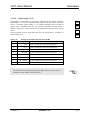
Settings for Parameters 018, 036, 054, and 072 ............................... 4-93
Settings for Parameters 019, 037, 055, and 073 ............................... 4-94
Settings for Parameters 020, 038, 056, and 074 ............................... 4-95
Parameter Associations between Planes, Measurement Units, and
the Number of Decimal Digits .......................................................... 4-95
Settings for Parameters 021, 039, 057, and 075 ............................... 4-96
Settings for Parameters 022, 040, 058, and 076 ............................... 4-97
Point-to-point Feedrate Parameter Assignments and Settings .......... 4-97
Settings for Parameters 027, 045, 063, and 081 ............................... 4-98
Settings for Parameters 028, 046, 064, and 082 ............................. 4-100
Settings for Parameters 029, 047, 065, and 083 ............................. 4-101
Aerotech, Inc.
Version 1.1
U511 User’s Manual
List of Tables
Table 4-77.
Table 4-78.
Settings for Parameters 030, 048, 066, and 084 ............................. 4-102
Settings for Parameters 31,49,67, and 85 ....................................... 4-103
Table 5-1.
Table 5-2.
Table 5-3.
Table 5-4.
Table 5-5.
Table 5-6.
Table 5-7.
Table 5-8.
Table 5-9.
Table 5-10.
Table 5-11.
Table 5-12.
Table 5-13.
Table 5-14.
Programming Conventions Used in This Manual ............................... 5-1
Single Character Arguments for Programming................................... 5-2
Supported Functions........................................................................... 5-3
Mathematical Operators and their Evaluation Hierachy..................... 5-4
Relative Position Registers ................................................................. 5-5
Absolute Position Registers................................................................ 5-6
Real Time Feedback Position Registers ............................................. 5-6
Real Time Commanded Position Registers ........................................ 5-7
A/D Channel Registers ....................................................................... 5-8
UNIDEX 511 Programming Commands ............................................ 5-9
Optional Arguments.......................................................................... 5-16
Comparison Operators...................................................................... 5-49
The Port to 8 X 3 I/O Connector Relationship ................................. 5-53
Motor Phase Labels and Hall States ................................................. 5-63
Table 6-1.
Table 6-2.
Table 6-3.
Table 6-4.
Table 6-5.
Table 6-6.
Table 6-7.
Table 6-8.
Table 6-9.
Table 6-10.
Table 6-11.
Table 6-12.
Table 6-13.
Table 6-14.
Table 6-15.
Enable RS-232 Remote Mode Sequence ............................................ 6-3
Auto Run a Program Communication Sequence................................. 6-3
Block Run a Program Communication Sequence ............................... 6-4
Program Abort Communication Sequence ......................................... 6-4
Service Request On Sequence ............................................................ 6-5
Service Request Off Sequence............................................................ 6-6
Set Service Request Character Sequence............................................ 6-6
Service Request Response Sequence.................................................. 6-6
Enable Hold Mode Sequence ............................................................. 6-7
Disable Hold Mode Sequence ............................................................ 6-7
Trigger Command Sequence .............................................................. 6-8
Print Error Message Sequence............................................................ 6-8
Immediate Command Sequence ......................................................... 6-9
Format of Return Data Command Sequence .................................... 6-10
Values of “n” and Feedback Type for the Axis Positions
Commands........................................................................................ 6-11
Print Axis Position Sequence............................................................ 6-11
Status Byte Bit Assignments............................................................. 6-12
Serial Pol Sequence .......................................................................... 6-13
Values of “n” and Corresponding Status for the PSn Command ...... 6-13
Print Status Sequence ....................................................................... 6-16
Read Register Sequence ................................................................... 6-16
Write Register Sequence .................................................................. 6-17
Bit Definitions for Register 0 ........................................................... 6-17
Write Parameter Sequence................................................................ 6-18
Read Parameter Sequence ................................................................ 6-18
Save Parameters Sequence ............................................................... 6-19
Hardware Reset Sequence ................................................................ 6-19
Upload File Sequence....................................................................... 6-21
Sequence of Commands when Downloading Files ........................... 6-22
Table 6-16.
Table 6-17.
Table 6-18.
Table 6-19.
Table 6-20.
Table 6-21.
Table 6-22.
Table 6-23.
Table 6-24.
Table 6-25.
Table 6-26.
Table 6-27.
Table 6-28.
Table 6-29.
Version 1.1
Aerotech, Inc.
xix
List of Tables
xx
U500 User’s Manual
Table 6-30.
Table 6-31.
Table 6-32.
Table 6-33.
Table 6-34.
Table 6-35.
Print Directory Sequence.................................................................. 6-22
Print Program “File” Sequence......................................................... 6-23
Read Variable Sequence ................................................................... 6-23
Delete File Sequence ........................................................................ 6-24
Help Menu Command Sequence....................................................... 6-24
Software Version Command Sequence............................................. 6-25
Table 7-1.
Table 7-2.
Table 7-3.
Software Status Diagnostics ............................................................... 7-6
Axis Position Diagnostics................................................................... 7-7
Hardware Status Diagnostics .............................................................. 7-7
Table 8-1.
Table 8-2.
Table 8-3.
Table 8-4.
Table 8-5.
Table 8-6.
Table 8-7.
Menu Items on the Axis Scope Window............................................. 8-3
File Menu Options in Axis Scope....................................................... 8-4
Trigger Menu Options in Axis Scope ................................................. 8-6
Troubleshooting the Autotune Process ............................................. 8-15
Initial Servo Parameter Values ......................................................... 8-18
Servo Gain Values ............................................................................ 8-26
Initial Servo Parameter Values - Tach Tuning.................................. 8-30
Table 10-1.
Table 10-2.
Table 10-3.
Table 10-4.
Table 10-5.
Table 10-6.
Table 10-7.
Table 10-8.
Table 10-9.
Table 10-10.
Table 10-11.
Table 10-12.
Table 10-13.
Table 10-14.
Table 10-15.
Table 10-16.
Table 10-17.
Table 10-18.
Table 10-19.
Encoder Connector Pinouts for Axis 1 Through 4 (J2 - J5).............. 10-3
COM1 Interface Connector Pinouts.................................................. 10-3
COM2 Interface Connector Pin Connections ................................... 10-4
16 IN/8 OUT Connector ................................................................... 10-5
UNIDEX 511/Opto 22 Connection Information............................... 10-6
8 X 3 I/O Bus Connector Pinouts (J12) .......................................... 10-10
Control Board Current Limiting Resistor Locations for Optoisolated Inputs................................................................................. 10-11
Opto-isolated Output Pin Locations................................................ 10-12
AUX I/O Connector Pinouts (J10).................................................. 10-13
External Voltages and Resistances for the Emergency Stop Input . 10-15
Joystick Interface Connector Pinouts (J6) ...................................... 10-15
IEEE-488 / GPIB Interface Connector Pinouts (J8) ....................... 10-16
Motor Connector Pinouts (J20-J23)................................................ 10-16
Control Board Jumper “JP” Description (JP1-JP15) ...................... 10-17
Interface Board jumper “JP” description (JP1-JP46) ..................... 10-19
Encoder Terminating Resistor Locations and Values. .................... 10-21
Control Board Test Points .............................................................. 10-22
U511 Control Board ‘PSO Encoder Bus’ Connector Pinouts (P6). 10-23
Electrical Specifications ................................................................. 10-25
Table 11-1.
Table 11-2.
Table 11-3.
Table 11-4.
Table 11-5.
Table 11-6.
Table 11-7.
Table 11-8.
Troubleshooting for Stepper Motors (and Related) Problems .......... 11-2
Troubleshooting for Servo Related Problems................................... 11-4
Troubleshooting for Problems Involving Fault Conditions .............. 11-5
Troubleshooting for Homing Related Problems ............................... 11-7
Troubleshooting for RS-232 Related Problems ................................ 11-7
Troubleshooting for IEEE-488/GPIB Related Problems .................. 11-8
Fuse Replacement Part Numbers ...................................................... 11-8
Preventative Maintenance................................................................. 11-9
Aerotech, Inc.
Version 1.1
U511 User’s Manual
List of Tables
Table C-1.
Hall State Table ..................................................................................C-3
Table D-1.
Table D-2.
iSBX-IO48 Pinouts............................................................................ D-2
iSBX-IO48 Control Words................................................................ D-5
Table F-1.
Table F-2.
System Commands Supported by the U511........................................ F-1
Motion/Flow Commands Supported by the U511 .............................. F-2
Table G-1.
Table G-2.
Table G-3.
Table G-4.
Table G-5.
Table G-6.
Table G-7.
Jumper Settings for Converter Demodulator Adjust Mode ............... G-2
Jumper Settings for Over-temperature Thermistor Input................... G-3
RDP Board Extension Bus Address Settings..................................... G-3
Inductosyn or Resolver Jumper Settings............................................ G-3
Oscillator Frequency Configuration for RCN5.................................. G-4
Oscillator Frequency Configuration for Capacitors........................... G-4
Bit Resolution Configuration; RCN1 Through RCN4 on RDP
Board ................................................................................................. G-5
Setting “Position channel” (x38) for the RDP Board ........................ G-7
Setting “Primary feedback setup code” (x40) for the RDP Board..... G-7
RDP Board Pinouts ........................................................................... G-8
RDP Board Test Points.................................................................... G-10
Table G-8.
Table G-9.
Table G-10.
Table G-11.
∇ ∇ ∇
Version 1.1
Aerotech, Inc.
xxi
List of Tables
xxii
U500 User’s Manual
Aerotech, Inc.
Version 1.1
U511 User’s Manual
Preface
PREFACE
The Preface provides an overview of topics covered in each chapter and conventions used
in this manual. This manual contains information on the following topics:
CHAPTER 1:
INTRODUCTION
Chapter 1 contains an overview of the UNIDEX 511 motion control system, as well as a
sample system diagram. This chapter also contains precautionary notes about installing
and using the UNIDEX 511 motion control system.
CHAPTER 2:
GETTING STARTED
This chapter contains information about the components comprising the UNIDEX 511
system, unpacking and inspecting the equipment, and contains a quick, to the point,
installation and setup of the U511 control system. This includes connecting cables and
wiring, verifying feedback and limits, and jogging an axis.
CHAPTER 3:
USER’S INTERFACE
Information regarding the front panel controls of the U511 and the liquid crystal display
(LCD) screens appearing on the front panel is found in Chapter 3. Also provided is a
complete list of menu items displayed through the UNIDEX 511 front panel interface.
Sample screens are illustrated for all functions.
CHAPTER 4:
PARAMETERS
This chapter provides information that helps the operator to understand and configure the
parameters within the UNIDEX 511 system. Appropriate parameter configuration
optimizes the UNIDEX 511 for an application. Chapter 4 includes discussions of all
software parameters, motor and feedback configurations, and other topics related to the
operation and configuration of the UNIDEX 511 system.
CHAPTER 5:
PROGRAMMING COMMANDS
Chapter 5 supplies information required to understand the UNIDEX 511 programming
environment. Included is an in-depth discussion of individual programming commands.
CHAPTER 6:
REMOTE MODE OPERATION
Information about controlling the U511 remotely through one of the RS-232 ports or the
IEEE-488 parallel port is found in Chapter 6.
CHAPTER 7:
WINDOWS INTERFACE AND UTILITIES
This chapter contains information about the Windows Utilities. These utilities include a
parameter editor, an axis scope screen, a diagnostic screen, and a file transfer utility. The
utilities run on any PC and operate remotely from the U511 using the RS-232 standard.
CHAPTER 8:
TUNING SERVO LOOPS
Chapter 8 provides information about servo loops and proper tuning techniques.
Version 1.1
Aerotech, Inc.
xxiii
Preface
U511 User’s Manual
CHAPTER 9:
PROGRAMMING EXAMPLES
This chapter contains sample applications highlighting UNIDEX 511 features, parameter
settings, and sample programs.
CHAPTER 10: HARDWARE DETAILS
Chapter 10 supplies a variety of technical specifications for the UNIDEX 511. These
specifications include test points, jumper configurations, encoder signal specifications,
pinouts, outputs, bus specifications, and others.
CHAPTER 11: TROUBLESHOOTING
This chapter provides a reference tool if problems with the UNIDEX 511 arise.
APPENDIX A: GLOSSARY OF TERMS
Appendix A contains a list of definitions of terms used in this manual.
APPENDIX B: WARRANTY AND FIELD SERVICE
Appendix B contains the warranty and field service policy for Aerotech products.
APPENDIX C: SETTING UP AN AC BRUSHLESS MOTOR WITH
THE UNIDEX 511
Appendix C contains a procedure for setting up AC brushless motors with the U511.
APPENDIX D: iSBX-IO48 BOARDS
This Appendix explains how to set up and program optional iSBX-I048 boards.
APPENDIX E: U511 BACKUP UTILITY
Appendix E contains information on the DOS utility for backing up or restoring
parameter files, configuration files, and user program files.
APPENDIX F: UNIDEX 11 EMULATION SOFTWARE
Appendix F contains information about the optional software that allows the UNIDEX
511 to emulate the UNIDEX 11.
APPENDIX G: THE RDP-PC RESOLVER-TO-DIGITAL BOARD
Information explaining how to set up and install optional RDP-PC resolver-to-digital
boards, is given in Appendix G.
INDEX
The index contains a page number reference of topics discussed in this manual. Locator
page references in the index contain the chapter number (or appendix letter) followed by
the page number and the reference.
xxiv
Aerotech, Inc.
Version 1.1
U511 User’s Manual
Preface
MANUAL CONVENTIONS
Throughout this manual the following conventions are used:
•
•
•
•
•
•
•
•
Use of "n" within a program block signifies that any axis (X, Y, Z or U) or drive
(1, 2, 3, or 4) may be inserted.
When mixed with small letters, capitalized letters within a command indicate the
minimum entry for that command (e.g., DIsable). Most commands are given in
capital letters.
The terms UNIDEX 511 and U511 are used interchangeably throughout this
manual.
Italic font is used to illustrate syntax and arguments for programming
commands.
Double quotation marks (“ ”) are used to indicate U511 parameter names.
Underlined letters refer to an <ALT> - letter keystroke.
Hexadecimal numbers are listed using a preceding "0x" (for example, 0x300,
0x12F, 0x01EA, etc.,) to distinguish them from decimal numbers.
An “x” preceding a parameter number represents the axis number (1, 2, 3 or 4)
for the corresponding axis (X, Y, Z, or U), respectively. Therefore, parameter
x38 (the “Position channel”), for example, actually corresponds to four distinct
parameters:
138 for the “Position channel” of axis X
238 for the “Position channel” of axis Y
338 for the “Position channel” of axis Z, and
438 for the “Position channel” of axis U
•
•
•
•
The terms ENTER and <Return> are used interchangeably throughout this
document when referring to the keyboard.
Within the index, a bold locator page number (e.g., Components, 1-1) indicates
that the reference is part of an illustration. An italic locator page number (e.g.,
OP500 Cable Pinouts, 5-7) indicates that the reference is part of a table. Text
references are shown in a standard serif font (e.g., Software Setup, 3-1).
Graphic icons or keywords may appear in the outer margins to provide visual
references of key features, components, operations, or notes.
Danger and/or Warning symbols (see right) appear in the outer margins next to
important precautions. Failure to observe these precautions could result in
serious injury and/or damage to the equipment.
DANGER
Version 1.1
Aerotech, Inc.
WARNING
xxv
Preface
U511 User’s Manual
•
The following statements apply wherever a Warning or Danger symbol appears
within this manual. Failure to observe these precautions could result in serious
injury to those performing the procedures and/or damage to the equipment.
If the equipment is used in a manner not specified by the manufacturer,
the protection of the equipment may be impaired.
WARNING
To minimize the possibility of electrical shock and bodily injury, make
certain that the mains power supply is disconnected before opening the
chassis.
WARNING
To minimize the possibility of electrical shock and bodily injury, make
certain that all of the electrical power switches are in the off position
prior to making any electrical connections.
WARNING
To minimize the possibility of electrical shock and bodily injury when
any electrical circuit is in use, ensure that no person comes in contact
with the circuitry.
DANGER
When this controller is installed within a system, mechanical motion
may occur. Care must be exercised that all personnel remain clear of
any moving parts.
DANGER
To minimize the possibility of bodily injury, disconnect mains power
supply. Make certain that all electrical power switches are in the off
position prior to making any mechanical adjustments.
DANGER
Protection ground connection symbol “W”
WARNING
•
This manual uses the symbol “∇ ∇ ∇” to indicate the end of a chapter.
∇ ∇ ∇
xxvi
Aerotech, Inc.
Version 1.1
U511 User’s Manual
Introduction
CHAPTER 1: INTRODUCTION
In This Section:
• Overview of the UNIDEX 511 System ............................... 1-1
• Ordering Information........................................................... 1-3
• Options and Accessories...................................................... 1-4
• Safety Procedures and Warnings......................................... 1-5
1.1.
Overview of the UNIDEX 511 System
The UNIDEX 511 (or U511) system is a stand-alone multiaxis motion controller (refer to
Figure 1-1). The U511 controller contains up to four integral amplifiers and all the
circuitry necessary to interface with up to four positioning stages. The UNIDEX 511
contains 48 digital I/O lines, two serial ports, an IEEE-488 parallel port, joystick
interface, and the ability to support ISA expansion boards. A Windows-compatible
utility program is shipped with each UNIDEX 511 system. It communicates with the
U511 through one of the RS-232 ports and allows the user to perform software updates,
run diagnostics, edit parameters, transfer files, and graphically tune and observe motion
performance. The U511 also contains a flash memory-based, read/write hard drive. All
parameters and user programs are stored here. A typical system is illustrated in
Figure 1-2.
Figure 1-1.
Version 1.1
UNIDEX 511
Aerotech, Inc.
1-1
Introduction
U511 User’s Manual
Figure 1-2.
1-2
The UNIDEX 511 System Diagram
Aerotech, Inc.
Version 1.1
U511 User’s Manual
1.2.
Introduction
Ordering Information
Table 1-1 lists U511 series options that are available from Aerotech, Inc. For complete
ordering information, refer to the Aerotech Motion Control Catalog.
Table 1-1.
*
Basic Motion Controllers
Controller
Description
U511x-y-v1-0
One-to-two axis UNIDEX 511 with integral power supply and
interconnection panel for all signals
U511x-y-v1-v2
Three-to-four axis UNIDEX 511 with integral power supply and
interconnection panel for all signals
Specify package style "x" as follows:
S = Desktop
R = Rack mount
Specify AC power "y" as follows:
A = 115 VAC
B = 230 VAC
C = 100 VAC
D = 208 VAC
Specify DC bus voltage "v1" and “v2” as follows:
30 = ±30 VDC
40 = 40 VDC
80 = 80 VDC
160 = 160 VDC
Table 1-2 lists the Aerotech motor drivers that can be used with the UNIDEX 511.
Version 1.1
Aerotech, Inc.
1-3
Introduction
U511 User’s Manual
Table 1-2.
Available Motor Drivers compatible with UNIDEX 511
Motor Driver
Description
AM8007C (Microstepping)
Microstepping motor driver, 7 A cont., 7 A peak, 20
kHz PWM, 40-80 V bus
DS16020C (DC Brush)
DC Brush:, 10 A cont. 20 A peak, 20 kHz PWM,
40-160 V bus
DS16030C (DC Brush)
DC Brush:, 15 A cont. 30 A peak, 20 kHz PWM,
40-160 V bus
AS32020C-Fn
AC brushless servo motor driver, 10 A cont., 20 A
peak, 20 kHz PWM, 40-160 V bus
AS3005LC-Fn
AC brushless servo motor driver, 3 A cont., 5 A peak,
linear DC 30 V bus
1.3.
Options and Accessories
A variety of options and accessories may be purchased with the UNIDEX 511 to enhance
its standard operation. Table 1-3 lists the Aerotech options and accessories that can be
used with the UNIDEX 511 Series motion controllers. Brief descriptions of each option
follow.
Table 1-3.
Options and Accessories Available for the UNIDEX 511
Accessories
HW500
JBV
JI
PSO-PC
1-4
Description
3.6 inch handwheel assembly and cable (25-pin male “D” )
Joystick with digitizing capability
Industrial joystick with digitizing capability
Programmable, position synchronized, laser firing control card
used to provide output signals based on the positions of up to three
axes
RDP-PC-n
Four-channel resolver-to-digital
inductosyn or resolver feedback
BRKBPS-x
Fail-safe brake control logic
converter
card
to
receive
PB8
Opto 22 interface board that provides 8 inputs or 8 outputs
PB16
Opto 22 interface board that provides 8 inputs and 8 outputs
PB24
Opto 22 interface board that provides 16 inputs and 8 outputs
Aerotech, Inc.
Version 1.1
U511 User’s Manual
1.4.
Introduction
Safety Procedures and Warnings
The following statements apply wherever the Warning or Danger symbol appears within
this manual. Failure to observe these precautions could result in serious injury to those
performing the procedures and/or damage to the equipment.
To minimize the possibility of electrical shock and bodily injury, make certain that
the mains power supply is disconnected before opening the chassis.
To minimize the possibility of electrical shock and bodily injury, make certain that
all of the electrical power switches are in the off position prior to making any
electrical connections.
To minimize the possibility of electrical shock and bodily injury when any electrical
circuit is in use, ensure that no person comes in contact with the circuitry.
When this controller is installed within a system, mechanical motion will occur. Care
must be exercised that all personnel remain clear of any moving parts.
To minimize the possibility of bodily injury, make certain that all electrical power
switches are in the off position prior to making any mechanical adjustments.
∇ ∇ ∇
Version 1.1
Aerotech, Inc.
1-5
Introduction
1-6
U511 User’s Manual
Aerotech, Inc.
Version 1.1
U511 User’s Manual
CHAPTER 2:
Getting Started
GETTING STARTED
In This Section:
• Introduction ................................................................ 2-1
• Unpacking the UNIDEX 511 Unit ............................. 2-1
• UNIDEX 511 Setup Flowchart................................... 2-2
• Installing Cables and Wiring ...................................... 2-3
• Software Configuration Considerations ..................... 2-4
• Special Startup Considerations................................... 2-4
• Enabling and Moving an Axis .................................... 2-7
• Internal System Wiring............................................... 2-7
2.1.
Introduction
This chapter steps the operator through unpacking the U511, connecting cables, and
verifying basic functionality.
2.2.
Unpacking the UNIDEX 511 Unit
Before unpacking any components, visually inspect the containers of the U511 system for
any evidence of shipping damage. If any such damage exists, notify the shipping carrier
immediately.
Remove the packing list from the UNIDEX 511 container. Make certain that the items
listed on the packing slip are contained within the package. The following items should
be found in every UNIDEX 511 system:
•
The UNIDEX 511 Motion Controller User’s Manual
•
Windows -compatible, 32 bit U511 utility software
•
UNIDEX 511 packing slip (listing products shipped with the order)
The following list of additional items may be included with the UNIDEX 511 system,
depending on the options and accessories that have been specified:
•
Motor connector cables
•
JBV or JI joystick and cable
•
Handwheel assembly and cable
•
I/O cables or Opto 22 boards
•
RS-232 cable
Version 1.1
Aerotech, Inc.
2-1
Getting Started
U511 User’s Manual
2.3.
UNIDEX 511 Setup Flowchart
Figure 2-1 illustrates a flowchart providing an overview of the installation process from
connecting the cables to jogging an axis.
Connect Cables
and Wiring
Verify
Feedback
Verify Limits
Configure
Servo Loop
Move Axes
Figure 2-1.
2-2
Flowchart Overviewing the Installation/Configuration Process
Aerotech, Inc.
Version 1.1
U511 User’s Manual
2.4.
Getting Started
Installing Cables and Wiring
System installation varies with the number and types of components that have been
purchased from Aerotech, Inc. to complement the UNIDEX 511 PC bus controller. The
following descriptions may not be applicable to all systems. Figure 2-2 is an illustration
of the rear panel connectors.
(left) Encoder Input 1
(left) Encoder 1, 5V OK
Serial Tag
(right) Encoder Input 2
(right) Encoder 2, 5V OK
13
J2
1
13
J3
1
25
AXIS 1
14
25
AXIS 2
14
DS7
DS5
13
(left) Encoder Input 3
(right) Encoder Input 4
25
AEROTECH
World Headquarters:
101 Zeta Drive
Pittsburgh, PA 15238 USA
(left) Encoder 3, 5V OK
(left) Joystick Interface
(right) Encoder 4, 5V OK
(center) Communications Port 1
(right) Communications Port 2
AXIS 3
13
14
25
1
J5
AXIS 4
14
DS6
DS4
8
15
J6
1
JOYSTICK
Opto I/O, User Interrupt, Brake, Emergency Stop,
And Analog I/O
USA: (412) 963-7470 Sales FAX: (412) 963-7459
USA Service FAX: (412) 963-7009
1
J4
5
9
9
19
37
1
J7
5
COM 1 6
9
J10
1
AUX. I/O
20
J8
1
COM 2
6
UK: 0734-817274 FAX: 0734-815022
Deutschland: 0911-52031 FAX: 0911-5215235
12
IEEE 488/GPIB Interface
J9
24
AXIS 4
AXIS 3
AXIS 2
AXIS 1
16 In/8 OUT 5V OK
J22
J21
25
J20
8 x 3 I/O Bus to OPTO
22 PB8, PB16, PB24
13
DS3
16 IN/8 OUT Digital I/O to
OPTO 22 PB8, PB16, PB24
8 x 3 I/O Bus 5V OK
J23
1
IEEE 488/GPIB
50
1
J11
16IN/8OUT
26
DS2
25
J12
1
50
8 X 3 I/O BUS
26
AC TAG
Figure 2-2.
Rear Panel Connectors of the U511
•
The round 14-pin plastic connectors are for connecting to the motors
•
The 25-pin “D” type connectors are for connecting to the encoder and limits
Aerotech positioning systems have two cables, one for the motor and one for the encoder.
The encoder cable and motor cable must be connected to corresponding channels.
Note: 1. Protective earthing is through mains power connection
2. Supply connection is mains power cord (mains power disconnect)
3. Protective earthing connection is indicated by the symbol “W”.
Cables must not be connected or disconnected from the U511 while power is
applied. Doing so may cause damage to the system or its components.
Before connecting the U511 to its power source, compare the desired input power to
the required input power indicated by the AC power tag (rear of the U511).
Version 1.1
Aerotech, Inc.
2-3
Getting Started
U511 User’s Manual
2.5.
Software Configuration Considerations
The UNIDEX 511 can be configured for a variety of motor and feedback devices.
Modification of this configuration can be accomplished from the Setup menu screen. The
configuration information is saved internally as a parameter file “*.PRM.”
If a complete system was purchased from Aerotech, including positioning stages and
cables, the UNIDEX 511 already contains a functional parameter file named
“xxxxxx.PRM”; where “xxxxxx” refers to the sales order number and serial number.
For a detailed discussion of the parameters listed in this section (and others) refer to the
individual parameter listings found in Chapter 4: Parameters.
2.6.
Special Startup Considerations
It is recommended that several functions be verified prior to enabling an axis for motion.
To facilitate this verification process, a Diagnostics window is provided in the U511
software package. This Diagnostics screen displays hardware (limits, I/O, etc.) and servorelated information (traps, machine position, etc.) dynamically (in real time). It is useful
for system setup and debug purposes. The Diagnostics window is accessed from the
DIAG key on the main screen.
The UNIDEX 511 software also contains a tracking display window that shows position
data in real time. The position is displayed in programmable units that the operator may
define (e.g., mm, in, etc.). The axis positions can be viewed from the MDI mode or the
program screens.
Make certain that all system traps and faults are enabled prior to initiating any axis
movement. For more information, refer to the faults, traps, and mask parameters in
Chapter 4: Parameters.
IMPORTANT
2.6.1. Feedback Verification
Before enabling any axis, is it important to verify the feedback from the motors. This is
done using the axis position display. The tracking display should be stable while the axis
is stationary (that is, the values in the axis position display windows should not change),
although slight movement with high resolution systems is normal.
2-4
Aerotech, Inc.
Version 1.1
U511 User’s Manual
Getting Started
Feedback phasing may be verified by manually turning the motor. Clockwise/counterclockwise rotation should produce an increasing/decreasing display. If not, feedback
phasing is incorrect. The Diagnostics window will always display CW rotation as
increasing feedback.
Motor direction for rotary motors (clockwise or counter-clockwise), is always
referenced by “looking into” the shaft end of the motor. For linear motors, the
positive direction is defined as movement away from the motor forcer’s integral
wiring.
Make certain that the UNIDEX 511 is appropriately configured for the type of
motor being driven.
IMPORTANT
2.6.2. Limit Verification
Limit verification is extremely important in the startup of the UNIDEX 511 system.
Improperly configured limits can cause damage to system components and can pose
safety hazards to operators and others. Limit verification requires the operator to disable
each axis, manually engage each limit, and then check the state of that limit input using
the Diagnostics window. The Diagnostics window will display the state of limit inputs as
either an “H” (for “high”) or an “L” (for “low”). Depending on their polarity, the limits
should change from high to low or from low to high when activated. Normally closed
limit switches go from low to high when activated. Normally open limit switches go from
high to low when activated. If no change is observed, the limit system is faulty. Refer to
Chapter 4 of this manual for more information about limit parameters.
To prevent the possibility of personal injury or possible damage to the equipment, do
not enable the axes until the limits are working properly.
WARNING
Version 1.1
Aerotech, Inc.
2-5
Getting Started
U511 User’s Manual
2.6.3. Preliminary Servo Loop Setup
In the most general sense, control loops are systems that create output signals based on
(1) input signals and (2) a series of servo gains that define the output over a variety of
input criteria. These gains must be individually tailored to every unique application. The
process of manipulating these servo gains to provide the most desirable response is called
servo tuning. In UNIDEX 511 systems, servo loops are tuned using the servo gain
parameters.
In the UNIDEX 511 system, there are five tuning parameters associated with each axis.
Each set of servo tuning parameters must be properly configured before the associated
axis can be enabled. The five servo loop tuning parameters are listed in Table 2-1.
Table 2-1.
Servo Loop Tuning Parameters
Abbr.
“Kpos”
Description/Function
Position Loop Gain
“Ki”
Velocity Loop Integrator
“Kp”
Velocity Loop Proportional Gain
“Vff”
Velocity Feed Forward
“Aff”
Acceleration Feed Forward
Servo loop tuning should be done with the motors fully loaded. Inertia,
momentum, gravity, friction, and other forces effect the response of the system.
Preliminary servo loop setup consists of enabling the axis and tuning the servo loop for
the desired performance. Information on UNIDEX 511 parameters can be found in
Chapter 4: Parameters. Information on servo loop tuning can be obtained from Chapter 8:
Servo Loop Tuning.
If Aerotech stages are ordered with your UNIDEX 511 controller, the servo loop
gain parameters will already be set from the factory.
2-6
Aerotech, Inc.
Version 1.1
U511 User’s Manual
2.7.
Getting Started
Enabling and Moving an Axis
After performing the initial configurations, it is important to verify everything functions
properly. Enable and jog the axis from the Jog screen under the MDI screen. It is
recommended to initiate movement of the axis in “Freerun-low speed” mode. Also, check
the home cycle by pressing the home button.
2.8.
Internal System Wiring
The U511 wiring varies depending on the AC input voltage, number of axes, DC bus
voltage, and drive modules. A system wiring drawing is provided with the documentation
package for the U511. The system drawing contains information concerning fuse values
and some jumper settings.
Additional information about the U511 is located on the system serial label and AC
power tag (located on the rear of the U511). The serial label contains the customer order
number (required when calling customer service), system drawing number, and system
part number. The AC power tag includes AC power requirements, line voltage, and
current requirements.
∇ ∇ ∇
Version 1.1
Aerotech, Inc.
2-7
Getting Started
2-8
U511 User’s Manual
Aerotech, Inc.
Version 1.1
U511 User’s Manual
The User Interface
CHAPTER 3: THE USER INTERFACE
In This Section:
•
Introduction......................................................... 3-1
•
Control Panel ...................................................... 3-1
•
Power-up Screen ................................................. 3-3
•
Program Menu .................................................... 3-5
•
Setup Menu: Parameters ................................... 3-17
•
Diagnostics Menu ............................................. 3-20
•
Tune Menu........................................................ 3-28
•
MDI Menu ........................................................ 3-31
3.1.
Introduction
The user interface consists of a front control panel and a software program that produces
a series of text screens in the viewing area. To operate the controller, the user uses the
keypad of the front control panel to manipulate information on the text screens. This
section discusses the control panel and the text screens.
3.2.
Control Panel
The standard control panel consists of a power switch, a 28-item sealed membrane
keypad, and an eight by 40 character liquid crystal display (LCD). Refer to Figure 3-1.
The LCD displays a series of screens holding information that can be viewed, selected, or
altered by operating certain keys on the keypad. The keypad allows users to access all the
utilities of the U511.
Figure 3-1.
Version 1.1
Control Panel
Aerotech, Inc.
3-1
The User Interface
U511 User’s Manual
A description of the keys and their functions follows.
•
•
•
•
•
•
•
•
Function Keys (F1 - F5). Located directly beneath the LCD, these keys allow the
user to activate corresponding functions that appear above them in the viewing area.
Such choices include functions that allow the user to quit the screen, go to the next
screen, go back a screen, and a host of other commands that are specific to the screen
display. The screens and the corresponding commands are discussed later in this
chapter. These keys are also programmable. See the SKEY command in Chapter 5.
RESET Key. This key performs a hardware reset function equivalent to turning the
power switch off and on.
PAUSE Key. This key toggles the pause/feedhold state. The current state of the
function can be determined from the MDI window or the Diagnostics screen. Global
subroutine calls “:Pauseon”/“:Pauseoff” are executed.
ABORT Key. This key causes all axes to ramp to a stop under servo control. Global
subroutine “:Abort” is executed.
FLTACK Key. This key causes the same action as the abort key, but in addition, it
clears any fault conditions. Any axis in a limit will be moved out. Global subroutine
“:Faultack” is executed.
Number Pad. Including a “+/-” key and a decimal key, the numerical keypad allows
users to enter positive and negative integers and decimal numbers into designated
locations in the viewing area.
INS and DEL keys. Insert and delete keys are used during text editing. When insert
is active, the cursor will appear as a full block. The DEL key will remove the
character pointed to by the cursor. The INS key also changes the “Copy” function to
the “Paste” function.
Cursor/Jog Keys (arrows). The cursor/jog keys have a two-fold purpose. In normal
mode, they move the cursor up and down, left and right through the information on
the viewing area so users can access the appropriate item on the screen. When in jog
mode, the cursor keys are used to move the axes.
In addition to the keypad, there is a QWERTY compatible keyboard port on the front
panel so an optional keyboard can be used to type commands in directly.
3-2
Aerotech, Inc.
Version 1.1
U511 User’s Manual
3.3.
The User Interface
Power-up Screen
When the U511 is first powered-up, the screen provides information on the U511
software version and amount of free memory. It also reveals whether remote mode is
enabled. In addition, this screen lists a Main menu of five major U511 functions, any of
which can be activated by pressing one of the function keys (F1-F5) below the screen.
The Power-up screen is shown in Figure 3-2.
Unidex 511 - Software Version 1.01
Free Memory 48226 (bytes)
Program Setup
F1
F2
Figure 3-2.
Diag
Tune
MDI
F3
F4
F5
Power-Up Screen
The following is a description of the five selectable functions (F1-F5) on the Power-up
screen:
F1 Program
The Program function allows the user to run programs, edit files,
copy and delete files, and digitize programs.
F2 Setup
The Setup function provides the user the ability to check, change,
and save parameters.
F3 Diag
The Diagnostics function allows the user to check status, fault
conditions, and communication operations.
F4 Tune
The Tune function allows the user to tune, check or change tuning
parameters, and save tuning parameters.
F5 MDI
The MDI function allows the user to operate the joystick, enter
individual program commands, and perform jog operations.
Activating one of these functions opens other screens with additional function choices on
them. These function submenus either carry out some related operation or lead, in turn, to
more screens. This series of menus and submenus is illustrated in Figure 3-3. Each
submenu is related somehow to the function that activated it. For example, the File
function under the Program menu leads to a screen called File Operations where users can
copy or delete files. The menus under Setup and Diagnostics shown in Figure 3-3 are not
selectable functions but “pages” of information that can be accessed with the “Next”
function.
In the sections that follow, screens are discussed in a top down fashion with the first Main
menu function discussed under a major section heading, and all the submenus beneath it
discussed in subsections under the major heading. In each section, the screen is described
first and then the actions of the corresponding functions are listed.
Version 1.1
Aerotech, Inc.
3-3
The User Interface
U511 User’s Manual
Figure 3-3.
3-4
U511 Menus Activated by the Function Keys
Aerotech, Inc.
Version 1.1
U511 User’s Manual
3.4.
The User Interface
Program Menu
Upon hitting the F1 key in the Power-up screen, the Program screen appears. Refer to
Figure 3-4. The Program screen allows the user to select program-related operations such
as running programs, editing, copying files, deleting files, and digitizing programs. This
screen also reveals U511 status information. The first line shows whether the U511 is in
incremental or absolute mode, the manual feed override (MFO) percentage, and the
feedrate. The next four lines display axis position and status information.
Program
X
Y
Z
U
Inc Mfo 100 F960.0/min
0.000 mm Enabled
0.000 mm Enabled
0.000 mm Enabled
0.000 mm Enabled
Run
Edit
File
Digit
Quit
F1
F2
F3
F4
F5
Figure 3-4.
Program Screen
There are five functions or commands on this screen, four of which lead to other screens.
The following is a description of the selectable functions under the Program screen (F1F5):
F1 Run
F2 Edit
F3 File
F4 Digit
F5 Quit
The Run function loads and runs programs.
The Edit function edits files and programs.
The File function copies or deletes U511 files.
The Digit function digitizes a program using a joystick.
The Quit function exits or quits the Program screen and returns to
the Main menu.
The functions leading to other screens are discussed below.
3.4.1. Program Menu: the Run Submenu
Choosing F1 under the Program screen leads to the Running Program screen. First,
however, the Load Program screen is displayed. The Load Program screen is used to
select the program to be loaded and run. Refer to Figure 3-5. To select a program, use the
cursor keys to move the cursor to the desired program. The selected program will be
shown in reverse video and also listed in the first line of the screen. Press the ENTER key
to load the selected program. If the U511 is currently running a program, this screen will
not be displayed–the Running Program screen is displayed instead.
Version 1.1
Aerotech, Inc.
3-5
The User Interface
U511 User’s Manual
Load Program:
TEST1.PRG
TEST5.PRG
TEST2.PRG
PgDown
*.*
F1
F2
Figure 3-5.
TEST1.PRG
11 10/10/97 09:46PM
31 08/21/97 09:50PM
13 10/10/97 09:45PM
Quit
F3
F5
F4
Load Program Screen
There are three selectable functions under the Load Program screen. These are described
below:
F1 PgDown/PgUp
This function moves one screen down or up through the list of
displayed files. Toggle between PgDown and PgUp by
reversing the direction with the cursor keys.
This function toggles between displaying all files (*.*) or just
program files (*.prg). The function key label shows the
extension that will be selected when F2 is pressed.
The Quit function exits or quits this operation and returns to
the Program screen.
F2 *.*/*.prg
F5 Quit
After a program has been selected and loaded (when ENTER is pressed), the Running
Program screen is displayed. Refer to Figure 3-6. This screen is used to start, control, and
monitor programs. The program and line being executed are listed in the first line of the
screen. Axis position and status information appears in the center of the screen. The axis
position information is automatically updated as the program runs.
X
Y
Z
U
Running Program: TEST1.PRG Line:1
0.000 mm Enabled
0.000 mm Enabled
0.000 mm Enabled
0.000 mm Enabled
Auto
F1
Cycle
Stop
Display
Quit
F2
F3
F4
F5
Figure 3-6.
3-6
Running Program Screen
Aerotech, Inc.
Version 1.1
U511 User’s Manual
The User Interface
This screen has five selectable functions that are described below:
F1 Auto/Single
F2 Cycle
F3 Stop
F4 Display
F5 Quit
The Auto/Single key determines if the program is to run
automatically (Auto) or by executing one block at a time (Single).
Cycle is used to start and step through programs.
Stop is used to stop a running program. All axis motion will
terminate and the program will be unloaded from memory.
Display allows the user to monitor the running program. Executing
program lines can be displayed on the screen by pushing this key.
This slows down block processing time of the U511 and is only
recommended for program debugging.
Quit will exit the Run Program screen and will prompt the user if a
program is running. A program is allowed to run in the background
after pressing this key.
3.4.2. Program Menu: the Edit Submenu
Pressing the F2 key in the Program screen brings up the Edit submenu. The Edit submenu
is a series of screens. First, the Edit File screen, which is used to select the file to be
edited, appears. Refer to Figure 3-7. To select a file, use the up and down arrow keys or
the PgDown/PgUp function to move the cursor. The selected file is shown in reverse
video. The selected file name or “untitled” in the case of a new file, appears in the first
line. Press ENTER to begin editing.
Edit File: TEST1.PRG
TEST1.PRG
11 10/10/97 09:46PM
TEST5.PRG
31 08/21/97 09:50PM
TEST2.PRG
13 10/10/97 09:45PM
PgDown
F1
*.*
F2
Figure 3-7.
Last
New
Quit
F3
F4
F5
Edit File Screen, Edit File Submenu
There are five selectable functions on the Edit File screen:
F1 PgDown/PgUp
F2 *.*/*.prg
F3 Last
F4 New
F5 Quit
Version 1.1
This function moves one screen down or up through the list of
displayed files. Toggle between PgDown and PgUp by
reversing the direction with the cursor keys.
This function toggles between displaying all files (*.*) or just
program files (*.prg). The function key label shows the
extension that will be selected when F2 is pressed.
This function recalls the last selected file or program.
New generates a new program.
The Quit function exits or quits this operation.
Aerotech, Inc.
3-7
The User Interface
U511 User’s Manual
The Program Editor screen (refer to Figure 3-8) is displayed after a program has been
selected and loaded. A program may be edited using an external keyboard. If there is no
keyboard, menu-assisted editing can be entered by pushing the Commands key (F4). If F4
is pushed when the cursor is on a line that contains a command, the syntax for that
command will appear in a special screen. The command can then be modified using the
submenus specific to that command. If F4 is pushed on a blank program line, the Edit
Command screen appears where the user can choose the desired command from the
displayed list. When editing the program in menu-assisted mode, the up and down arrow
keys may be used to scroll through the program.
Editing: “TEST1.PRG”
HOME XY
DelLine
PgDown
F1
F2
Figure 3-8.
Line:1
Digit Commands
F3
F4
Quit
F5
Program Editor Screen
There are five selectable commands on the Program Editor screen, one of which leads to
other screens. Below is a description of the functions (F1-F5) on the Program Editor
screen:
F1 DelLine
F2 PgDown/PgUp
F3 Copy/Paste
F4 Commands
F5 Quit
3-8
The DelLine function deletes the selected line of a file.
This function moves one screen down or up through the
command lines. Toggle between PgDown and PgUp by
reversing the direction with the cursor keys.
This function is used to copy one line of a file. To paste, press
the INS key (F3 becomes Paste) and position the cursor to
where the line is to be inserted and press F3.
This function summons the Edit Command screen where
users can build a command without using the keyboard. It
also helps the user with program command syntax.
The Quit function is used to exit or quit this operation. It
summons the “Save As:” screen so the program can be saved.
Aerotech, Inc.
Version 1.1
U511 User’s Manual
The User Interface
The following screen (Figure 3-9) is an example of an Edit Command screen. Pressing the
Commands key (F4) while the cursor is on a blank line accesses the Edit Command
screen. The Edit Command screen is used to enter commands without using a keyboard
and to help with program command syntax. The most commonly used commands are
displayed in the first screen. Other commands follow alphabetically. A command can be
selected by using the PgUp, PgDown, and arrow keys to locate the cursor on the desired
command then pressing ENTER. After pressing ENTER, a specialized command screen,
which will help the user with the program command syntax, will be displayed.
Use of the Edit Command screen is only necessary when a keyboard is unavailable.
Index
ENABLE
DISABLE
HOME
FREERUN
DWELL
INDEX
CC
CW
Fa
IO
IOSET
Loop
IF
GOTO
:label
Press ENTER for syntax
PgUp
PgDown
F1
F2
Figure 3-9.
F3
SLEW
LINEAR
OUT
NEXT
;comment
Quit
F4
F5
Edit Command Screen
This screen has three selectable functions that are described below:
F1 PgUp
F2 PgDown
F5 Quit
This function is used to page up through the commands.
This function is used to page down through the commands.
The Quit function is used to exit or quit this operation.
The specialized command screens that appear after pressing ENTER on the Edit
Command screen (or by pressing Commands [F4] while the cursor is on a command in
the Program Editor screen) differ depending on the command that was selected. An
example of one of these specialized command screens is shown in Figure 3-10. This
screen is for the INDEX command. The first line of the screen shows the file name and
the line of the program that the command is being added to. The next line shows the name
of the command. The third line shows the syntax for the command. In this case, the syntax
structure means that the axis to be moved (X, Y, Z, or U) must be followed by a distance
(a, b, c, or d), followed by the feedrate of the move for each axis (XFe, XFf, etc.). The
fourth line is where the user builds the command to be inserted into the program using the
functions at the bottom of the screen. To insert a modified command into the Program
Editor, the user must press ENTER after the command has been built. When this is done,
the program returns to the Program Editor screen with the new command displayed in it.
Version 1.1
Aerotech, Inc.
3-9
The User Interface
U511 User’s Manual
Editing:”TEST1.PRG”
Line:2
Index
INDEX Xa Yb Zc Ud XFe YFf ZFg UFh
INDEX
AXIS
FEED
Continue
ASCII
BACK
F1
F2
F3
F4
F5
Figure 3-10. Specialized Command Edit Screen
The functions at the bottom of the specialized command screens differ depending on the
command selected. The AXIS (F1) and FEED (F2) functions are specific to the INDEX
command. These functions open screens where the user can select and insert axis and
feedrate characters into the command. The following general commands are found on
most specialized command edit screens.
F3 Continue
F4 ASCII
F5 Back
Returns the user to the Edit Command screen and appends the next
command to the present command.
Opens the ASCII utility so users can enter characters without using
a keyboard.
Returns the user to the Program Editor screen without inserting the
modified command into the program.
Leave the Program Editor by pressing the Quit key. Upon leaving the Program Editor, the
“Save File As:” screen (Figure 3-11) is displayed. This screen allows the user to change
or assign a file name, return to the edit session, save and exit, or just exit.
Save File As: TEST1.PRG
ASCII
F1
Return
F2
F3
Save
F4
NoSave
F5
Figure 3-11. “Save File As:” Screen
3-10
Aerotech, Inc.
Version 1.1
U511 User’s Manual
The User Interface
This screen has four selectable functions, one of which leads to other screens. These
functions are described below:
F1 ASCII
F3 Return
F4 Save
F5 NoSave
Opens the ASCII utility so users can enter or change the name of
the file.
Return will return the user to the program being edited.
Save will store the file being edited and exit edit mode.
NoSave will exit edit mode without saving the file.
3.4.3. The ASCII Utility
This screen enables users to build commands or file names, including non-numerical
characters, using only the keys on the front panel. If the user has a keyboard, the
commands or file names can be typed in directly.
Use of the ASCII utility is only necessary when a keyboard is unavailable.
The ASCII utility appears in many forms. An example screen is shown in Figure 3-12.
This screen is for editing a file name and would appear after the user pressed “ASCII”
(F1) in the “Save File As:” screen. The important features on this page are the two lines of
ASCII characters and the functions at the bottom of the page.
The data entry point is automatically placed to the right of “Save File As:” The cursor is
situated on the first line of the ASCII characters. To insert an ASCII character, use the
function keys at the bottom of the screen or the arrow keys on the front panel to move the
cursor to the desired character, then press ENTER. The selected character will appear at
the entry point. This can be repeated until the command or filename is built.
Save File As: TEST1.PRG
!"#$%&’()*+,-./0123456789:;<=>?
@ABCDEFGHIJKLMNOPQRSTUVWXYZ[\]^_
TabLeft TabRight HOME
END
F1
F2
F3
F4
QUIT
F5
Figure 3-12. The ASCII Utility
Version 1.1
Aerotech, Inc.
3-11
The User Interface
U511 User’s Manual
The five function keys on the ASCII utility are described below:
F1 TabLeft
F2 TabRight
F3 Home
F4 End
F5 Quit (or Back)
Moves the cursor to the left five characters in the ASCII list.
Moves the cursor to the right five characters in the ASCII list.
Moves the cursor to the beginning of the ASCII character list.
Moves the cursor to the end of the ASCII character list.
Registers the changes and returns to the original screen with
the command or file name inserted.
3.4.4. Program Menu: the File Submenu
Upon choosing the F3 key in the Program screen, the user enters the file operations mode.
The File Operations screen (Figure 3-13) is used to copy and delete files. Move the cursor
to the desired file (it will appear in reverse video), then select Copy (F4) to make a copy
of a file, or Del (F3) to erase the file. The F2 function toggles between displaying all files
(*.*) or just program files (*.prg). The function key label shows the extension that will be
selected when F2 is pressed.
File Operations
TEST1.PRG
11 10/10/97 09:46PM
TEST5.PRG
31 08/21/97 09:50PM
TEST2.PRG
13 10/10/97 09:45PM
PgDown
F1
*.*
F2
Del
F3
Copy
F4
Quit
F5
Figure 3-13. File Operations Screen
3.4.5. Program Menu: The Digitize Submenu
The Digitize function allows the user to edit a file and use the joystick to generate
positioning commands in the program. This function may be used to generate linear,
circular (clockwise or counterclockwise), or spline move commands.
When Digitize is selected from the Program submenu, an Edit File screen, similar to the
one in the Edit submenu is displayed. Refer back to Figure 3-7. The user is required to
input the file to be digitized. Once the file is selected or new file is chosen, the Program
Editor screen for the Digitize submenu will be displayed. See Figure 3-14. This screen
functions identically to the Program Editor screen of the Edit submenu except that the
Copy/Paste function is replaced with a “Digit” function. This function enables the joystick
and allows the user to select the type of command generated.
3-12
Aerotech, Inc.
Version 1.1
U511 User’s Manual
The User Interface
Pressing the joystick “C” button generates program lines. Refer to Figure 3-15. Move
commands are generated in absolute or incremental mode depending on the current state
of the U511 (see the Programming command in the Chapter 5).
Editing: “TEST1.PRG”
HOME XY
DelLine
PgDown
F1
F2
Line:1
Digit Commands
F3
F4
Quit
F5
Figure 3-14. Program Editor Screen, Digitize Menu
Following is a description of the selectable functions (F1-F5):
F1 DelLine
F2 PgDown/PgUp
F3 Digit
F4 Commands
F5 Quit
Version 1.1
The DelLine function deletes the selected line of a file.
This function moves one screen down or up through the
command lines. Toggle between PgDown and PgUp by
reversing the direction with the cursor keys.
This function summons the Digitizing screen where users can
select the digitize mode and insert commands with the
joystick.
This function summons the Edit Command screen where
users can build a command without using the keyboard. It
also helps the user with program command syntax. The Edit
Command screen in the Digitize submenu is the same routine
as in the Edit submenu.
The Quit function is used to exit or quit this operation.
Aerotech, Inc.
3-13
The User Interface
U511 User’s Manual
Button C
Button C
Button A
Button A
Button B
Button B
JBV-xx Joystick
JI Joystick
Figure 3-15. Joysticks Showing the “C” Button
In the digitizing screens that follow, the Mode (F1) key is used to select the digitizing
mode. The screens differ depending on the mode. All screens, however, show the same
information at the top of the screen. First the program name is displayed, followed by an
abbreviation that shows whether the U511 is in incremental or absolute mode. Next, the
mode of joystick slew operation is displayed. The joystick can be in linear, circular, or
spline mode and it can be in low speed (l), high-speed (h), or position (p) mode. The “B”
button on the joystick selects the latter mode. The axes that are under joystick control are
also displayed at the top of the screen. These are shown in axis pairs because the joystick
can, at most, control two axes of motion at once. The “A” button toggles between axis
pairs. When digitizing mode is entered, all enabled axes are available for joystick control.
Linear Digitizing
The Linear Digitizing screen is shown in Figure 3-16. The linear digitizing mode uses the
joystick to generate linear move commands in a program. This mode is selected by
pressing the Mode (F1) key until “Linear” is displayed at the top of the screen. Use the
joystick to slew the axes to the desired point and then press the “C” button on the joystick
to incorporate the move. Only axis positions that have changed will be entered into the
program. Any number of moves may be incorporated before quitting the screen. To see
the commands, press Quit (F5), which returns the user to the Program Editor screen with
the commands inserted.
3-14
Aerotech, Inc.
Version 1.1
U511 User’s Manual
The User Interface
UNTITLED.PRG
X
0.000
Y
0.000
Z
0.000
U
0.000
Inc Linear Slew l X,Y
mm Enabled
mm Enabled
mm Enabled
mm Disabled
Move to linear point
Mode
F1
F2
F3
Quit
F4
F5
Figure 3-16. Linear Digitizing Screen
The following is a description of the selectable functions (F1-F5):
F1 Mode
F5 Quit
Mode selects type of digitizing command.
Quit inserts the linear moves and returns the user to the Program
Editor.
Circular Digitizing
The Circular Digitizing screen is shown in Figure 3-17. Circular digitizing uses the
joystick to generate clockwise (CW) or counterclockwise (CCW) move commands in a
program. This mode is selected by pressing the Mode (F1) key until “Cir” is displayed at
the top of the screen. The circle is calculated based on three points on the arc (see
margin). The starting point is the current position. Move the axes to the first point, press
the joystick “C” button, and then repeat for the second point. The U511 automatically
calculates the circle direction. After the first point on the circle is entered, the user may
reenter it by pressing the F2 key. This will overwrite the previously recorded position
while preserving the starting point.
X
Y
Z
U
UNTITLED.PRG
0.000
0.000
0.000
0.000
F2
First Digitized Point
Current/Starting Point
Inc Cir(XY) Slew l X,0
mm Enabled
mm Enabled
mm Enabled
mm Disabled
Move to first circle point
Mode
Haxis
Vaxis
F1
Second Digitized Point
F3
F4
Quit
F5
Figure 3-17. Circular Digitizing Screen
Version 1.1
Aerotech, Inc.
3-15
The User Interface
U511 User’s Manual
There are four selectable functions in the menu at the bottom of the page. These functions
(F1-F5) are described below.
F1 Mode
F3 Haxis
Mode selects type of digitizing command.
Haxis selects the circle horizontal axis displayed at the top of the
screen.
Vaxis selects the circle vertical axis displayed at the top of the
screen.
Quit inserts the circular move and returns the user to the Program
Editor
F4 Vaxis
F5 Quit
Spline Digitizing
The Spline Digitizing screen is shown in Figure 3-18. Pushing the Mode key (F1) until
“Spline” appears at the top of the screen enters the spline mode. This mode is very similar
to linear digitizing except that the commands generated do not contain the “LI”
instruction. Use the joystick to slew the axes to the desired points and press the joystick
“C” button. Any number of points may be entered. The user must place a “SPLINE ON”
command at the beginning of a block of points and a “SPLINE OFF” command at the end
of the block. These commands can be added in the previous Program Editor screen using
the keyboard or the Commands function.
X
Y
Z
U
UNTITLED.PRG Inc Spline Slew l X,0
0.000 mm Enabled
0.000 mm Enabled
0.000 mm Enabled
0.000 mm Disabled
Move to spline point
Mode
F1
F2
F3
Quit
F4
F5
Figure 3-18. Spline Command Screen
The functions (F1-F5) at the bottom of the screen are described below:
F1 Mode
F5 Quit
3-16
Mode selects type of digitizing command.
Quit returns the program to the Program Editor.
Aerotech, Inc.
Version 1.1
U511 User’s Manual
3.5.
The User Interface
Setup Menu: Parameters
Upon hitting the F2 key in the Power-up screen, the Setup menu appears. The Setup
screens are used to check and change the U511 parameters. Setup consists of 11 screens
or “pages” with groups of related parameters on each. The pages are as follows:
Page
Number
1
2
3
4
5
6
7
8
9
10
11
Page Title
System Configuration
Serial Port #1 Setup
Serial Port #2 Setup
GPIB/IEEE-488 Setup
Axis Configuration
Servo Loop
Homing and Limits
Motor and Feedback
Fault Masks
Traps
Planes and Mapping
Parameters are classified as axis parameters if they are used for all four axes. All other
parameters are considered general parameters. Axis parameters are numbered 100 to 199,
200 to 299, 300 to 399, and 400 to 499 for axes one through four respectively. General
parameters are numbered 0 to 99 and 500 and up. Parameter type and number are
displayed in the upper right corner of all Setup screens. A general parameter page is
shown in Figure 3-19 and an axis parameter page is shown in Figure 3-20.
The page number is displayed at the top left of the page. The page title is displayed at the
top of the page. Scroll through parameters on a page by pressing the up and down arrows.
The Back (F1) and Next (F2) keys move through the parameter pages. F3 is a special
purpose key that selects the next axis or plane, depending on the parameter. It is also used
to toggle through a list of predefined choices in some cases.
To change a parameter value, there are several options. The line above the function keys
usually lists instructions for changing a parameter value. In most cases were the parameter
has a numerical value, simply scroll the cursor to the value to be changed and enter the
appropriate value through the keypad. Pressing the left/right arrow keys changes yes/no
parameter values. Any 0/1 fault mask bits are also toggled in this way. The Default (F4)
key sets the parameter to the factory default value.
Starting with software version 5.02, the default key will return a system-specific
“default” value. Otherwise, a general default value will be returned (see Appendix E:
Backup Utility).
Additional information concerning the setup parameters can be found in Chapter 4:
Parameters.
Version 1.1
Aerotech, Inc.
3-17
The User Interface
U511 User’s Manual
System Configuration
Page 1
Auto enable axes
Auto run program
Axis calibration file
Parameter file
Back
F1
Next
F2
F3
Gen 600
XYZU
u511.prm
Default
Exit
F4
F5
Figure 3-19. System Configuration Page (General Parameters)
Axis Configuration
Page 5
Axis 1, 100
Metric conversion factor
1.00000000
Metric conversion factor
1.00000000
Maximum accel/decel
1.00000000
Positive move is CW
yes
[machine steps / program steps]
Back
Next
Axis
Default
Exit
F1
F2
F3
F4
F5
Figure 3-20. Axis Configuration Page (Axis Parameters)
There are from four to five functions on the general and axis pages. The following
describes typical functions (F1-F5) on these pages:
F1 Back
F2 Next
F3 Axis
F4 Default
F5 Exit
3-18
Back selects the previous setup page.
Next selects the following setup page.
Axis selects the axis (1-4). This information is displayed at the top
of the page along with the parameter number.
Starting with software version 5.02, the Default key will return a
system-specific “default” value. Otherwise, a general default value
will be returned (see Appendix E: Backup Utility).
Exits this operation and returns to the “Save Changes?” screen.
This screen gives the user the opportunity to save the parameter
changes to the current file, save the changes as another file name,
or quit and return to the Main menu without recording the changes.
Aerotech, Inc.
Version 1.1
U511 User’s Manual
The User Interface
3.5.1. Setup Menu: The Fault Masks Page
The Fault Masks page (Page 9) is used to setup the fault mask parameters. The Fault
Masks page is shown in Figure 3-21. This page differs from the other Setup pages, as it is
the only page that requires another page to change parameter values. The user need not
enter the hexadecimal numbers in any fault mask. As shown in the figures, the page
instructs the user to press ENTER to expand the mask. The expanded Fault Masks page
breaks down the selected fault mask into its individual bits so the user can edit them one
at a time. An example of an expanded Fault Masks page is shown in Figure 3-22.
Fault Masks
Page 9
Axis 1, 161
AUX output
FFFFFFF00100
Halt queue
FFFFFFF00000
Abort motion
FFFFFFFF717F
Enable brake
FFFFFFF00000
Press ENTER to expand mask!
Back
Next
Axis
Default
Exit
F1
F2
F3
F5
F4
Figure 3-21. Fault Masks Page
The functions at the bottom of the page are the same as for any axis parameter.
Global fault masks
Page 9
Axis
Position error
0
RMS current error
0
Integral error
0
CW Hardware
1
1, 155
Back
F1
F2
F3
F4
F5
Figure 3-22. Expanded Fault Masks Page
The complete fault mask spans several pages. Use the up and down arrow keys to scroll
through the list of faults. The Back key (F5) returns the user to the original Fault Masks
page. To toggle between a 0 and a 1, press the left and right arrow keys.
Version 1.1
Aerotech, Inc.
3-19
The User Interface
3.6.
U511 User’s Manual
Diagnostics Menu
Upon hitting the F3 key in the Main menu, the Diagnostics menu appears. Like the
parameters, the diagnostic items are arranged into groups or pages. The Diagnostics pages
provide information concerning the hardware and system status of the U511. These pages
are as follows:
Page
Number
1
2
3
4
5
6
7
8
Page Title
Hardware Status
Primary I/O
System Status
Position
Active Limits
Servo Faults
Secondary I/O
Terminal
The user changes nothing on these pages. They are for information only. The page
number is at the top left of the page and the title is at the top center. On most pages, the
top right of the page lists the axis numbers (1, 2, 3, and 4) for the column of status
information below. Diagnostics menu pages all have the same function keys at the bottom
of the page. Toggle through the pages by hitting the Back (F1) or Next (F2) function
keys. The Quit key returns the user to the Main menu screen. The pages in the
Diagnostics menu are described below.
3.6.1. Diagnostics Menu: Hardware Status Page
The Hardware Status page displays status information concerning limits, amplifier faults,
and encoder faults. The Hardware Status page is shown in Figure 3-23. Table 3-1
describes the components of the Hardware Status page.
Page 1
Hardware Status
CW hardware limit
CCW hardware limit
Home hardware limit
Amplifier fault
Encoder sine fault
Encoder cosine fault
Back
Next
F1
F2
F3
F4
1
H
H
H
H
Y
Y
2 3 4
H H H
H H H
H H H
H H H
Y Y Y
Y Y Y
Quit
F5
Figure 3-23. The Hardware Status Page
3-20
Aerotech, Inc.
Version 1.1
U511 User’s Manual
Table 3-1.
The User Interface
Hardware Status Diagnostics
Field
Status Description
CW hardware limit
Indicates the current hardware input level of the CW limit input
(H = +5 V level, L = GND level).
CCW hardware limit
Indicates the current hardware input level of the CCW limit
input (H = +5 V level, L = GND level).
Home hardware limit
Indicates the current hardware input level of the Home input
(H = +5 V level, L = GND level).
Amplifier fault
Shows whether an amplifier is in a fault condition (H = +5 V
level, L = GND level).
Encoder sine fault
Records whether there is an invalid differential sine signal on
the encoder (Y = fault, N = no fault). A broken wire, loss of
encoder power, or low signal amplitude can cause this.
Encoder cosine fault
Records whether there is an invalid differential cosine signal on
the encoder (Y = fault, N = no fault). A broken wire, loss of
encoder power, or low signal amplitude can cause this.
3.6.2. Diagnostics Menu: Primary I/O Page
The Primary I/O page (refer to Figure 3-24) displays status information concerning digital
I/O and the A/D inputs. Table 3-2 describes the components of the Primary I/O page.
Page 2
Primary I/O
Inputs
1111111111111111
Outputs
00000000
A/D input 1
0.00
A/D input 2
0.00
A/D input 3
0.00
A/D input 4
0.00
Back
Next
Quit
F1
F2
F3
F4
F5
Figure 3-24. Primary I/O Page
Version 1.1
Aerotech, Inc.
3-21
The User Interface
U511 User’s Manual
Table 3-2.
Primary I/O Status Diagnostics
Field
Status Description
Inputs
Shows inputs on the 16 IN/8 OUT bus (0 = GND level, 1 = +5 V
level).
Outputs
Shows outputs on the 16 IN/8 OUT bus. A 0/1 on the output
corresponds to the programmed output level.
A/D inputs 1-4
Shows the direct analog/digital converter voltage (0-5 V) for the
corresponding input.
3.6.3. Diagnostics Menu: System Status Page
The System Status page (Page 3) displays the manual feed override (MFO) value,
Emergency Stop status, Brake status, Pause status, Joystick status, and the Status Word.
The System Status page is shown in Figure 3-25. Table 3-3 describes the components of
the System Status page.
Page 3
System Status
MFO
Emergency Stop
Brake
Pause
Joystick ABC
Status Word
Back
Next
F1
F2
F3
100.0%
N
Y
N
HHH
00000F
Quit
F4
F5
Figure 3-25. System Status Page
3-22
Aerotech, Inc.
Version 1.1
U511 User’s Manual
Table 3-3.
The User Interface
System Status Diagnostics
Field
Status Description
MFO
Shows the current manual feed override percentage from 0% to
199%. Also displayed in the MDI window if not equal to 100%.
Emergency Stop
Indicates current E-Stop status (Y = on, N = off) if E-Stop bit in
any fault mask is enabled and E-Stop input is true. Also shown in
the MDI window.
Brake
Indicates brake status (Y = on, N = off). The brake is a U511
option requiring additional hardware and is enabled in the fault
mask.
Pause
Indicates pause status (Y = pause, N = no pause). Pressing the
PAUSE button on the front panel toggles the pause state.
Joystick ABC
Indicates current functionality of the joystick buttons. A, B, and C
do not physically correspond to the joystick buttons. The C on the
screen is the interlock signal that must be low (L) for the joystick
to operate. A and B correspond to the joystick “A” and “B”
buttons. Pressing joystick “A” or “B” buttons causes the display
to go from H to L. The joystick “C” button activates both “A” and
“B” buttons/status bits.
Status Word
Indicates the internal “read status (5)” value.
3.6.4. Diagnostics Menu: Position Page
The Position page (refer to Figure 3-26) displays In Position status, Marker status, and the
individual Axis Positions. Table 3-4 shows components of the Position page.
Page 4
Position
In Position
Marker
Axis 1 Position [0000]
Axis 2 Position [2000]
Axis 3 Position [0000]
Axis 4 Position [0000]
Back
Next
F1
F2
F3
1 2 3 4
* * * *
* - * 0
0
0
0
Quit
F4
F5
Figure 3-26. The Position Page
Version 1.1
Aerotech, Inc.
3-23
The User Interface
U511 User’s Manual
Table 3-4.
Position Diagnostics
Field
Status Description
In Position
Indicates whether or not the axis is in its commanded position
(“*” = in position, “-” = not in position).
Marker
Indicates when the encoder marker has been found (“*” = found,
“-” = not found).
Axis 1-4 Position [ ]
Shows current axis position in machine steps. The positions
shown in brackets are useful for resolver setup. For resolvers, they
represent the resolver-to-digital converter 16-bit value.
3.6.5. Diagnostics Menu: Active Limits Page
The Active Limits page (refer to Figure 3-27) displays limit status information. This page
differs from the Hardware Status page because the polarity is programmable and the axis
must be enabled to have an active limit. Components of the Active Limits page are shown
in Table 3-5.
Page 5
Active Limits
1 2 3 4
CW hardware limit
- - - CCW hardware limit
- - - Home hardware limit
- - - CW software limit
- - - CCW software limit
- - - Back
Next
F1
F2
Quit
F3
F4
F5
Figure 3-27. Active Limit Page
Table 3-5.
Active Limit Diagnostics
Field
3-24
Status Description
CW hardware limit
Indicates whether the CW hardware travel limit is active
(“*” = active, “-” = inactive).
CCW hardware limit
Indicates whether the CCW hardware travel limit is active
(“*” = active, “-” = inactive).
Home hardware limit
Indicates whether the Home limit is active (“*” = active,
“-” = inactive).
CW software limit
Indicates if the software CW travel limit is active
(“*” = active, “-” = inactive”).
CCW software limit
Indicates if the software CCW travel limit is active
(“*” = active, “-” = inactive”).
Aerotech, Inc.
Version 1.1
U511 User’s Manual
The User Interface
3.6.6. Diagnostics Menu: Servo Faults Page
The Servo Faults page (refer to Figure 3-28) displays servo fault and trap information.
The axis must be enabled to show a fault. Table 3-6 shows components of the Servo
Faults page.
Page 6
Servo Faults
Feedback fault
Amplifier fault
Position trap
Velocity trap
Integral trap
RMS torque
Back
Next
F1
F2
F3
1
-
F4
2 3 4
- - - - - - - - - - - - Quit
F5
Figure 3-28. Servo Faults Page
Table 3-6.
Servo Fault Diagnostics
Field
Status Description
Feedback fault
Indicates whether there is a feedback fault (“*” = active fault, “-”
= no fault).
Amplifier fault
Indicates whether an amplifier is in a fault (“*” = active fault, “-”
= no fault).
Position trap
Indicates whether the position error exceeds value in parameter
x19 (“*” = position error > x19, “-” = no position trap).
Velocity trap
Indicates whether the velocity error exceeds value in parameter
x18 (“*” = velocity error > x18, “-” = no velocity trap).
Integral trap
Indicates whether integral error exceeds the parameter x20 value
(“*” = integral error > x20, “-” = no integral error trap).
RMS torque
Indicates whether RMS torque (drive current command) exceeds
the parameter x48 value (“*” = RMS torque > x48, “-” = no RMS
torque fault).
Version 1.1
Aerotech, Inc.
3-25
The User Interface
U511 User’s Manual
3.6.7. Diagnostics Menu: Secondary I/O Page
The Secondary I/O page (refer to Figure 3-29) displays the status of the 8 X 3 I/O bus and
the Hall inputs. Components of the Secondary I/O page are shown Table 3-7.
MSB
LSB
Page 7
Secondary I/O
I/O bank A
00
0000000
I/O bank B
00000000
I/O bank C
00000000
4
3
2
1
Hall Inputs CAB
101 101 101 101
Back
Next
F1
F2
Figure 3-29.
Table 3-7.
Axis No.
Quit
F3
F4
F5
Secondary I/O Page
Secondary I/O Diagnostics
Field
Status Description
I/O banks A-C
Shows the current input status of the 8 X 3 I/O bus if programmed
as inputs. When configured as outputs, shows the programmed
output value. See the IOSET and IO commands in Chapter 5:
Programming Commands.
Hall Inputs CAB
Applicable only with AC brushless motors. Indicates the state of
the Hall sensors. See Motor Setup (MSET) command in Chapter
5: Programming Commands.
3.6.8. Diagnostics Menu: Terminal Page
The Terminal page (refer to Figure 3-30) monitors serial and GPIB communications
between the U511 and a host system. This page may also be used to send characters. To
select the port to transmit to, press the up or down arrows. The selected port will have an
underline cursor (_). Other ports will have a solid block cursor. Type from the keyboard
or input from the front panel. These characters will be transmitted to the host system. An
“*” beside the port indicates that remote communications are active on that port. The
active components of the Terminal page are shown in Table 3-8.
3-26
Aerotech, Inc.
Version 1.1
U511 User’s Manual
The User Interface
Page 8
Terminal
Com 1 Tran:_
Rec :
Com 2 Tran:
Rec :
GPIB Tran:
Rec :
Back
Next
F1
F2
F3
Quit
F4
F5
Figure 3-30. Terminal Page
Table 3-8.
Active Components of the Terminal Page
Field
Tran:
Rec:
Version 1.1
Status Description
Sends and displays characters transmitted to the host system from
the selected port. Pressing ENTER will send the EOS (end of
string) character.
Displays characters received from any/all ports. Nonprintable
characters will be displayed in hexadecimal format and in
brackets.
Aerotech, Inc.
3-27
The User Interface
3.7.
U511 User’s Manual
Tune Menu
Upon pressing the F4 key in the Power-up screen, the Tune screen appears (refer to
Figure 3-31). The Tune screen is used for axis tuning. This screen can be used to
manually enter Kpos, Ki, Kp, Vff, and Aff gains. Use the up and down arrows to select
the field to be modified. Move the cursor to the desired field and enter the numerical
value. Press ENTER to activate the gain in the servo loop. Press Save (F4) to save the
new gain values to the parameter file.
Axis 1
Kpos 100
Ki
10000
Kp
600000
Vff
256
Aff
0
Distance (mm)
Bandwidth (Hz)
Frequency (Hz)
Damping
Axis
Auto
Restore
Save
Quit
F1
F2
F3
F4
F5
80.0000
35
1
.7
Figure 3-31. Tune Screen
There are five functions on this screen, which are described below:
F1 Axis
F2 Auto
F3 Restore
F4 Save
F5 Quit
Axis selects the axis displayed on the screen (1-4).
Performs autotuning. See below.
Restore sets the tuning values back to stored values.
Save stores tuning values/gains to the parameter file.
Quit is used to exit the tuning screen.
This screen can also be used to automatically calculate gains. The process is called
autotuning. The UNIDEX 511 does this by moving the motor in a progressively faster
back and forth motion and recording the current required for the move. This data is used
along with the user-specified Bandwidth and Damping parameters to calculate servo loop
gains.
Setting Distance and Frequency
The first step in autotuning is to set the Distance and Frequency parameters. The Distance
parameter determines how much the motor moves, and Frequency determines the speed of
movement during autotuning. Typical values are 25-100 mm for Distance and 1 Hz for
Frequency. If a RMS error occurs during autotuning, the Distance or Frequency may be
set too high. If the Distance is too low, the U511 responds with "Could not calculate
gains!"
3-28
Aerotech, Inc.
Version 1.1
U511 User’s Manual
The User Interface
Setting Bandwidth and Damping
The Bandwidth and Damping parameters specify the desired response of the motor. The
higher the Bandwidth, the better the stage performance will be. This means minimizing
velocity error, position error, and settling time. Higher Bandwidth numbers will result in
higher servo loop gains. A typical value of Bandwidth is 35 Hz.
The Damping parameter determines how the motor comes into position. A low Damping
value (.3) may allow the axis to come into position more quickly, but take longer to
completely settle. There may also be some overshoot at the end of the move. A value of .7
will ensure that there is minimal overshoot. A typical value of Damping is .5.
Procedure for Autotuning
1.
2.
3.
4.
5.
6.
7.
8.
Defeat Position and Velocity Error traps. This is done by modifying the
“Global fault mask” on Page 9 of the Setup Menu (see axis parameter
x55).
Set starting gains. If the user does not have "working" gains, set
Kpos = 1, Ki = 1000, Kp = 10,000, and Vff = 256.
Set excitation Distance and Frequency. Distance is in current units (mm
or in).
Typical Distance = 25 mm or 1 in (see text)
Typical Frequency = 1 Hz
Set desired bandwidth and damping. A Bandwidth of 10 Hz and
Damping of .5 are good starting points.
Run autotune by pressing the Auto key (F2).
Increase bandwidth by 5 Hz increments until system becomes loud or
unstable. Return to next lower bandwidth and retune.
Save gains to parameter file by pressing F4.
Re-enable Position and Velocity Error traps (see axis parameter x55).
Autotuning cannot be run on stepper motors, motors with tachometer feedback, or
dual loop systems.
See the autotuning portion of the Chapter 8 for additional information on autotuning.
Version 1.1
Aerotech, Inc.
3-29
The User Interface
U511 User’s Manual
3.7.1. Troubleshooting Autotuning
Some tips for troubleshooting autotuning are given in Table 3-9.
Table 3-9.
Troubleshooting the Autotune Process
Problem
System responds with
"Could not calculate
gains!"
Possible Causes / Solutions
An axis fault has occurred.
Ki and Kp must be set > 0.
Vff must be set to 256.
Current is too high, lower Distance or Frequency.
Tracking rate of feedback device has been exceeded, lower Distance
or Frequency.
Top feedrate trap occurs. Lower Distance or Frequency, or defeat
trap if allowed.
Motor makes a loud
noise and shuts off
immediately
Gains are set too high, decrease Ki and Kp.
Motor commutation parameters are incorrect (AC motors only).
Encoder signals are missing, verify in Diagnostics.
Motor does not move at
all
Encoder is damaged, verify on Diagnostics.
Motor is not enabled.
Motor is disconnected.
Amplifier has faulted. Shut system off for 30 seconds and retry.
3-30
Aerotech, Inc.
Version 1.1
U511 User’s Manual
3.8.
The User Interface
MDI Menu
Upon hitting the F5 key in the Power-up screen, the Machine Direct Input (MDI) screen
appears (refer to Figure 3-32). The MDI screen provides joystick control, jog operations,
and the ability to enter individual commands. This screen also shows U511 status
information. The first line relates whether the U511 is in incremental or absolute mode. It
also shows MFO percentage and the feedrate. The next four lines display axis position
and status information. Commands may be typed in using an external keyboard or menuassisted commands may be entered using the Commands (F4) function. The up and down
arrows scroll through a list of previously entered commands.
Incremental or
Absolute Mode
Manual Feed
Override Percentage
MDI
Inc Mfo 100 F600.0/min
0.000 mm Enabled
0.000 mm Enabled
0.000 mm Enabled
0.000 mm Enabled
X
Y
Z
U
JStick
F1
Feedrate
Jog
F2
Commands
F3
F4
Quit
F5
Figure 3-32. MDI Screen
There are four functions at the bottom of the screen, three of which lead to other screens.
They are described below.
F1 JStick
F2 Jog
F4 Commands
F5 Quit
Version 1.1
Opens the Joystick screen where axes can be positioned using the
joystick.
Opens the Jog screen where axes can be positioned using the left
and right arrow keys.
This function summons the Command screen where users can build
a command without using the keyboard. It also helps the user with
program command syntax. This is the same routine as in the
Program: Edit submenu.
Quit exits the MDI screen and returns to the Main menu.
Aerotech, Inc.
3-31
The User Interface
U511 User’s Manual
3.8.1. MDI Menu: Joystick Submenu
The joystick function screen is shown in Figure 3-33 This screen allows the operator to
move the axes to a desired point using the joystick. Axis position information will be
automatically updated on the screen. It will only activate if a joystick is connected to the
U511. Any pair of enabled axes will be selectable with the joystick “B” button. Pressing
the joystick “C” button or the Quit (F5) key terminates this screen.
MDI
Inc Mfo 100 Slew h x, 0
0.000 mm Enabled
0.000 mm Disabled
0.000 mm Disabled
0.000 mm Disabled
X
Y
Z
U
Quit
F1
F2
F3
F4
F5
Figure 3-33. JStick Screen
3.8.2. MDI Menu: Jog Submenu
The jog screen (refer to Figure 3-34) allows the user to move an axis under manual
control. Pressing the left or right arrow key does this. Axis motion will stop when the key
is released. The jog axis is shown in reverse video and is selected by pressing the up and
down arrow keys. Axis motion can be continuous (freerun) or of a fixed distance (index).
Refer to the Setup section for jog speed and distance parameters. This screen can also be
used to enable/disable or Home an axis. The currently selected axis is shown in reverse
video.
Jog:
Freerun 3.725 mm
-33.608 mm
4.900 mm
4.275 mm
X
Y
Z
U
High Speed
Enabled
Enabled
Enabled
Enabled
Arrows: UP/DN Select Axis, LF/RT Jog
High
Index
Disable
Home
Quit
F1
F2
F3
F4
F5
Figure 3-34. Jog Screen
3-32
Aerotech, Inc.
Version 1.1
U511 User’s Manual
The User Interface
There are five functions at the bottom of the screen. These are described below.
F1 High/Low
F2 Index/Freerun
F3 Enable/Disable
F4 Home
F5 Quit
This function selects high or low speed.
This function selects index or freerun mode.
This function will enable or disable the axis.
This function will Home the selected axis.
Quit exits the Jog screen.
3.8.3. MDI Menu: Commands Submenu
This screen is for menu-assisted command entry. Essentially it is the same screen as the
Command Edit screen under the Program: Edit submenu. Refer to Section 3.4.2: Program:
Menu: the Edit Submenu to receive instructions on using the Commands screen.
∇ ∇ ∇
Version 1.1
Aerotech, Inc.
3-33
The User Interface
3-34
U511 User’s Manual
Aerotech, Inc.
Version 1.1
U511 User’s Manual
Parameters
CHAPTER 4: PARAMETERS
In This Section:
• Introduction ............................................................ 4-1
• Page 1: System Configuration ................................ 4-7
• Pages 2 and 3: Serial Port #n Setup...................... 4-13
• Page 4: GPIB/IEEE-488 Setup............................. 4-15
• Page 5: Axis Configuration .................................. 4-16
• Page 6: Servo Loop .............................................. 4-32
• Page 7: Homing and Limits .................................. 4-41
• Page 8: Motors and Feedback............................... 4-49
• Page 9: Fault Masks.............................................. 4-67
• Page 10: Traps...................................................... 4-71
• Page 11: Planes and Mapping............................... 4-81
4.1.
Introduction
This chapter describes all of the parameters of the UNIDEX 511 system. Parameters are
assembled into 11 groups based on their appearance on “pages” in the Setup menu (F2).
Each page of the menu represents a group of related parameters. The sections in this
chapter are arranged according to these groups under a subtitle that has the name of the
page to which the parameters belong. Within these sections, parameters are presented in
the order in which they appear in the software. Additional sections are included to explain
topics that are closely related to the parameters. Table 4-1 shows a listing of the
parameters and their default values grouped by page.
For easy reference the parameter number is displayed in the margin beside the parameter
explanation. An example is illustrated in the margin to the right.
Table 4-1.
009
U511 Parameters Grouped by Page
Parameter
Number
Description
Default Value
Found on
Page #
4-7
Page 1: System Configuration
600
“Auto enable axes”
No axis enabled
4-7
601
“Auto run program”
None
4-7
602
“Axis calibration file”
None
4-7
603
“Parameter file”
U511.PRM
4-7
604
“Firmware file”
A:\U511.JWP
4-7
605
“M-code file”
None
4-7
Version 1.1
Aerotech, Inc.
4-1
Parameters
U511 User’s Manual
Table 4-1. U511 Parameters Grouped by Page (continued)
Parameter
Number
Description
Default Value
Found on
Page #
606
“Global subroutine file”
GLBSUB.PRG
4-8
607
“PSO-PC firmware file”
None
4-8
15
“PSO-PC DPRAM address” (hex address 0xnnnn)
0xD800
4-8
16
“PSO-PC I/O address” (hex address 0xnnn)
0
4-9
98
“Safe zone output bit 0,1-8”
0
4-9
99
“Option board setup code”
0
4-9
500
“User interrupt setup code”
0
4-10
90, 92, 94, 96
“A/D channel n joystick deadband”
0
4-10
91, 93, 95, 97
“A/D channel n center”
0
4-11
647
“Enable speaker” (y/n)
No
4-11
648
“Password”
None
4-12
501
“Abort on input high 0, 1-16”
0
4-12
4-13
Pages 2 and 3: Serial Port #n Setup
608, 617
“Baud rate” (bits per second)
9600
4-13
609, 618
“Data bits” (bits)
8
4-13
610, 619
“Stop bits” (bits)
1
4-13
611, 620
“Parity” (N, O, E)
N
4-13
612, 621
“End of string character”
10
4-13
613, 622
“Fast output?” (y/n)
Yes
4-13
614, 623
“Command ACK character”
6
4-14
615, 624
“Command NAK character”
21
4-14
616, 625
“Default configuration”
0
4-14
4-15
Page 4: GPIB/IEEE - 488 Setup
626
“GPIB address” (0-30)
2
4-15
627
“EOS character”
10
4-15
628
“Parallel Pol Response bit” (0-NONE or 1-8)
0
4-15
629
“Time out” (seconds)
30
4-15
630
“Default configuration”
0
4-15
4-16
Page 5: Axis Configuration
4-2
x00
“Metric conversion factor” (mach. steps/program step)
1.0
4-16
x01
“English conversion factor” (mach. steps/program step)
1.0
4-16
Aerotech, Inc.
Version 1.1
U511 User’s Manual
Table 4-1.
U511 Parameters Grouped by Page (continued)
Parameter
Number
x16
x11
x12
x13
x14
x15
x35
x37
x50
x51
x52
x71
x72
11, 12, 13, 14
x83
x84
x85
631, 632,633, 634
635, 636, 637, 648
639, 640, 641, 642
x25
x26
x27
x28
x29
x62
x24
x30
x31
x32
x33
x34
x78
Version 1.1
Parameters
Description
“Max accel/decel” (machine steps/ms/ms)
“Positive (+) move is CW” (y/n)
“Positive (+) jog same as + move” (y/n)
“Enable pause in freerun” (y/n)
“Enable MFO in freerun” (y/n)
“Enable axis calibration” (y/n)
“In position deadband” (machine steps)
“Backlash correction amount” (machine steps)
“Joystick high speed” (machine steps/sec)
“Joystick low speed” (machine steps/sec)
“Joystick absolute scale” (machine steps)
“Enable orthogonality table” (y/n)
“Enable 2-D error mapping” (y/n)
“Modulo rollover” (machine steps)
“Filter time constant” (ms)
“AUX output active high” (y/n)
“Reverse Joystick Directions”
“Jog low speed” (machine steps/ms)
“Jog high speed” (machine steps/ms)
“Jog distance” (machine steps)
Page 6: Servo Loop
“Kpos” (0-8,388,607)
“Ki” (0-8,388,607)
“Kp” (0-8,388,607)
“Vff” (0-8,388,607)
“Aff” (0-8,388,607)
“Loop update rate (* .25 ms)” (1-100)
“Enable Notch filter?” (y/n)
“Notch filter N0”
“Notch filter N1”
“Notch filter N2”
“Notch filter D1”
“Notch filter D2”
“Servo loop type”
Aerotech, Inc.
Default Value
1.00000000
Yes
Yes
Yes
Yes
No
10
0
40960
2560
10
No
No
0
0
Yes
No
10
25
4000
50
5000
100000
256
0
1
No
0.00000000
0.00000000
0.00000000
0.00000000
0.00000000
0
Found on
Page #
4-19
4-19
4-20
4-20
4-21
4-21
4-25
4-26
4-27
4-27
4-28
4-29
4-29
4-29
4-31
4-31
4-31
4-31
4-31
4-31
4-32
4-32
4-32
4-32
4-33
4-33
4-34
4-34
4-35
4-35
4-35
4-35
4-35
4-35
4-3
Parameters
Table 4-1.
U511 User’s Manual
U511 Parameters Grouped by Page (continued)
Parameter
Number
Description
Default Value
Found on
Page #
4-41
Page 7: Homing and Limits
x02
“Home direction CCW” (y/n)
Yes
4-42
x03
“Home switch normally open” (y/n)
Yes
4-43
x04
“Home feedrate” (machine steps/ms)
25.00000000
4-44
x06
“Home offset” (machine steps)
0
4-44
x09
“Limit switch normally open” (y/n)
Yes
4-45
x10
“Limit to mechanical stop” (machine steps)
2000
4-45
x22
“CCW software limit” (machine steps)
-140,737,488,355,327
4-46
x23
“CW software limit” (machine steps)
140,737,488,355,327
4-46
x74
“Use home limit during home” (y/n)
No
4-47
x75
“Safe zone - limit” (machine steps)
0
4-47
x76
“Safe zone + limit” (machine steps)
0
4-47
x77
“Limit debounce distance” (machine steps)
750
4-48
4-49
Page 8: Motor and Feedback
x38
“Position channel”
Axis # = Channel #
4-56
x39
“Velocity channel”
0
4-57
x40
“Position setup code”
3
4-58
x41
“Velocity setup code”
3
4-59
x42
“Amplifier type” (0-DC Brush, 1-AC Brushless, 2Step, 3-recirc)
0
4-60
x43
“Commutation cycles/rev”
4
4-61
x44
“Feedback steps/rev”
4000
4-62
x45
“Commutation phase offset” (0-359 degrees)
0
4-62
x46
“Stepper high current %” (0-100%)
70.0000
4-62
x47
“Stepper low current %” (0-100%)
35.0000
4-63
x63
“Microstepping resolution” (machine steps)
4000
4-63
x64
“Stepper correction” (y/n)
Yes
4-63
x65
“Stepper correction speed” (microstep/ms)
1.00000000
4-64
x66
“Base speed” (machine steps/ms)
0
4-64
x67
“Base speed advance” (0-359 degrees)
0
4-65
4-4
Aerotech, Inc.
Version 1.1
U511 User’s Manual
Table 4-1.
Parameters
U511 Parameters Grouped by Page (continued)
Parameter
Number
Description
Default Value
Found on
Page #
x68
“Phase speed” (machine steps/ms)
0
4-65
x69
“Phase speed advance” (0-359 degrees)
0
4-65
x79
“Primary DAC offset” (mV)
0
4-65
x80
“Secondary DAC offset” (mV)
0
4-65
x82
“Encoder factor”
0
4-66
x55
Page 9: Fault Masks
“Global fault mask”
FFFFFFFF319F
4-67
4-69
x56
“Disable”
FFFFFFF0EF87
4-69
x57
“Interrupt”
FFFFFFF00000
4-69
x58
“AUX output”
FFFFFFF00000
4-69
x59
“Halt queue”
FFFFFFF08E00
4-70
x60
“Abort motion”
FFFFFFFF9E78
4-70
x61
“Enable brake”
FFFFFFF00000
4-70
4-71
Page 10: Traps
x17
“Top feedrate” (machine steps/ms)
440.000000
4-71
x18
“Max velocity error” (0-8,388,607)
1000
4-72
x19
“Max position error” (0-8,388,607)
4000
4-73
x20
“Max integral error” (0-8,388,607)
655360
4-74
x48
“RMS current trap” (0-100%)
30.0000
4-75
x49
“RMS current sample time” (1-16,383 ms)
10000
4-77
x53
“Clamp current output” (0-100%)
100.0000
4-78
x54
“AUX fault output bit”
Axis # = Bit #
4-79
x70
“Amplifier fault active low” (y/n)
Yes
4-80
4-81
Page 11: Planes and Mapping
0
“Number of contour planes” (1,2,4)
1
4-84
1
“Keep position after reset?” (y/n)
No
4-86
2
“MFO pot offset” (0-255)
0
4-87
3
“Axis 1 plane 1-4 as XYZU”
1,X
4-88
4
“Axis 2 plane 1-4 as XYZU”
1,Y
4-88
5
“Axis 3 plane 1-4 as XYZU”
1,Z
4-88
Version 1.1
Aerotech, Inc.
4-5
Parameters
Table 4-1.
U511 User’s Manual
U511 Parameters Grouped by Page (continued)
Parameter
Number
4-6
Description
Default Value
Found on
Page #
6
“Axis 4 plane 1-4 as XYZU”
1,U
4-88
7
“Axis 1 gantry y/n slave 2,3,4”
None
4-90
8
“Axis 2 gantry y/n slave 1,3,4”
None
4-90
9
“Axis 3 gantry y/n slave 1,2,4”
None
4-90
10
“Axis 4 gantry y/n slave 1,2,3”
None
4-90
18, 36, 54, 72
“Segment time” (1-20 ms)
10
4-93
19, 37, 55, 73
“Ramp time” (ms)
150
4-94
20, 38, 56, 74
“Default to metric” (y/n)
Yes
4-95
21, 39, 57, 75
“Linear accel/decel” (y/n)
No
4-96
22, 40, 58, 76
“Contour feedrate” (program steps/ms)
16.00000000
4-97
23, 41, 59, 77
“X axis index feedrate” (program steps/ms)
16.00000000
4-97
24, 42, 60, 78
“Y axis index feedrate” (program steps/ms)
16.00000000
4-97
25, 43, 61, 79
“Z axis index feedrate” (program steps/ms)
16.00000000
4-97
26, 44, 62, 80
“U axis index feedrate” (program steps/ms)
16.00000000
4-97
27, 45, 63, 81
“Clamp feedrate” (program steps/ms)
256.00000000
4-98
28, 46, 64, 82
“Corner rounding time” (1-32000 ms)
150
4-98
29, 47, 65, 83
“Metric digits” (1-8)
3
4-101
30, 48, 66, 84
“English digits” (1-8)
4
4-102
31, 49, 67, 85
“Contouring mode”
0
4-103
Aerotech, Inc.
Version 1.1
U511 User’s Manual
4.2.
Parameters
Page 1: System Configuration
Page 1 parameters primarily allow the user to indicate which files will be run after reset.
Configuration parameters for the optional PSO-PC board are also included, as are
parameters for setting the joystick deadband and center position. These and other
parameters are explained in detail in this section.
4.2.1.
“Auto enable axes”
Parameter 600 selects the axes that are automatically enabled on power up. Axes X, Y, Z,
and/or U can be selected. To deselect an axis, simply delete the entry leaving the field
blank. No axes enabled is the default setting.
4.2.2.
“Auto run program”
Parameter 601 selects a program to be loaded and executed in auto mode after power up.
The default setting is a blank, meaning no program is to be executed. To deselect a file,
simply delete it, leaving the field blank.
4.2.3.
603
“Firmware file”
Parameter 604 is the file loaded to the DSP during reset. The default file is A:\U511.JWP.
4.2.6.
602
“Parameter file”
Parameter 603 specifies the file containing parameters 0-99 and axis parameters 100-199,
200-299, 300-399, and 400-499. The default file is U511.PRM. If the UNIDEX 511 is
factory configured by Aerotech, this field will contain a file name of the form
123456.PRM. The six-digit number is the Aerotech reference number for the system.
4.2.5.
601
“Axis calibration file”
Parameter 602 is the “Axis calibration file” loaded to the DSP during reset. The default
setting is blank; meaning no calibration file is to be used. To deselect a file, simply delete
it, leaving the field blank.
4.2.4.
600
604
“M-code file”
Parameter 605 is a file containing "M"-code definitions that can be accessed from any
program. The default setting is a blank; meaning no program is available. To deselect a
file, simply delete it, leaving the field blank.
Version 1.1
Aerotech, Inc.
605
4-7
Parameters
U511 User’s Manual
4.2.7.
606
Parameter 606 is a file containing global subroutines that can be called from any program.
The default setting is GLBSUB.PRG. To deselect a file, simply delete it, leaving the field
blank. The GLBSUB.PRG file contains skeleton subroutines that are automatically
executed when the PAUSE, ABORT, or FLTACK keys are pressed or when the system is
first powered up.
4.2.8.
607
“PSO-PC firmware file”
The UNIDEX 511 has several optional accessories that can be used to augment the
operation of the system. One such option is the PSO-PC card. Parameter 607 is the file
that is loaded to the PSO card after reset. If a PSO-PC card is installed, this field should
be set to "A:\PCPSO.FRM.” The default setting is blank; meaning no program is
available. To deselect a file, simply delete it, leaving the field blank. For more
information about the PSO-PC card, refer to the PSO-PC Operation and Technical
Manual (P/N: EDO105).
4.2.9.
015
“Global subroutine file”
“PSO-PC DPRAM address” (hex address 0xnnnn)
The UNIDEX 511 has several optional accessories that can be used to augment the
operation of the system. One such option is the PSO-PC card. If the PSO option is used
with the UNIDEX 511 system, then parameters 015 and 016 must be configured to permit
proper communications between the PSO-PC board and the U511. System parameter 015
specifies (in hexadecimal) the base address of the dual-ported RAM. System parameter
016 specifies the I/O port address.
By default, the PSO-PC is configured to use DPRAM base address 0x0D800 and I/O
address 310. For more information about the PSO-PC card, refer to the PSO-PC
Operation and Technical Manual (P/N: EDO105).
F
F
4-8
The dual PSO-PC hardware decodes 4K (4096) byte blocks of system memory.
The dual-ported RAM size is 2K (2048) bytes. Therefore, the dual-ported RAM
appears twice within the 4 K byte memory block. The default jumper settings of the
PSO-PC board map the dual-ported RAM to memory locations D800:0000 and
D800:0800. The first 2 K byte block should be used for programming consistency.
This parameter must agree with the hardware address setting specified by jumpers
JP16-JP23 of the PSO-PC board. Refer to the PSO-PC manual (EDO105) for more
information.
Aerotech, Inc.
Version 1.1
U511 User’s Manual
4.2.10.
Parameters
“PSO-PC I/O address” (hex address 0xnnn)
If the PSO option is used with the U511 system, then parameters 015 and 016 must be
configured to permit proper communications. Parameter number 016 specifies (in
hexadecimal) the host base address for use with the U511 motion controller. Set this
parameter to 0 to disable the board and to 310 to enable it. For more information about
the PSO-PC card, refer to the PSO-PC Operation and Technical Manual (P/N: EDO105).
This parameter must agree with the hardware address setting specified by jumpers
JP2-JP7 on the PSO-PC board. For additional information, refer to the PSO-PC
manual (EDO105).
4.2.11.
016
E
“Safe zone output bit 0,1-8”
Parameter 098 specifies which UNIDEX 511 output to turn on (low) when all axes are in
their specified Safe Zones. See parameters x75 and x76 under Homing and Limits for an
explanation of Safe Zone.
098
This parameter can have a value of zero or 1 through 8. A parameter value of zero, which
is the default value, defeats the safe zone function.
4.2.12.
“Option board setup code”
Parameter 099 indicates which option board is being used. The option board is
determined by the status of the first two bits of parameter 099. The configuration can be
changed by entering an appropriate decimal value for Parameter 099. The settings for
parameter 099 are given in Table 4-2.
bit #0:
Setting bit #0 causes the U511 to enable access to the 4EN
Option board. Inputs are read using the IN2 and IN3
commands. Outputs are written using the OU1, OU3, and OU4
commands.
bit #1
Setting bit #1 enables scanning of an optional iSBX encoder
card. The encoder position can be read from the U511’s
memory at L:1BC3.
bits #2-#23
Reserved.
Table 4-2.
Settings for Parameter 099
Parameter #
Range
Default Value
099
0 - 8388607
0
Version 1.1
099
Aerotech, Inc.
4-9
Parameters
U511 User’s Manual
4.2.13.
500
“User interrupt setup code”
Parameter 500 sets the usage of the user interrupt input. The usage is determined by the
status of the first two bits of parameter 500. The configuration can be changed by entering
an appropriate decimal value for the parameter. This input is active low. Settings for
parameter 500 are given in Table 4-3.
bit #0
Set to 1 to abort all axis motion on user interrupt.
bit #1
If set to 0, the UINT_N input will disable itself after the first
occurrence. If this bit is set to 1, the UINT_N input will
remain active.
bit #2-#23
Reserved.
Table 4-3.
Parameter #
Range
Default Value
500
0 - 8388607
0
4.2.14.
090
092
094
Settings for Parameter 500
“A/D channel n joystick deadband” Parameters
These parameters define the deadbands associated with the center position of the joystick.
There is no resulting motion when the joystick is within this band. The parameter value is
the number of A/D counts in the deadband. The default value is zero, which is internally
interpreted as 16 A/D counts for backward compatibility.
The parameter definitions are listed in Table 4-4. Parameters 090 and 092 are currently
not used because the joystick is connected to channel numbers 3 and 4. A/D channel
number 1 is normally the MFO input. A/D channel 2 is normally the user analog input.
096
Table 4-4.
Parameter #
F
4-10
Joystick Deadband Parameters
A/D Channel
Default Value
090
A/D Channel No. 1
0
092
A/D Channel No. 2
0
094
A/D Channel No. 3 (joystick vertical axis)
0
096
A/D Channel No. 4 (joystick horizontal axis)
0
The A/D converter is 8 bits scaled so that 0 V gives an output of 0 and +5 V gives
an output of 255. An A/D output of 128 corresponds to an input of +2.5 V.
Aerotech, Inc.
Version 1.1
U511 User’s Manual
4.2.15.
Parameters
“A/D channel n center” Position Parameters
These parameters specify the center position of the A/D inputs used for joystick mode.
This allows the joystick pot to be digitally centered or calibrated. The parameter value is
the number of A/D counts assigned to the center position. The default value is zero, which
is internally interpreted as 128 A/D counts (2.5 V) for backward compatibility.
The parameter definitions are listed in Table 4-5. Parameters 091 and 093 are currently
not used because the joystick is connected to channel numbers 3 and 4. A/D channel no. 1
is normally the MFO input. A/D channel 2 is normally the user analog input.
091
093
095
097
Table 4-5.
Joystick Center Position Parameters
Parameter #
A/D Channel
Default Value
091
A/D Channel No. 1
0
093
A/D Channel No. 2
0
095
A/D Channel No. 3 (joystick vertical axis)
0
097
A/D Channel No. 4 (joystick horizontal axis)
0
The A/D converter is 8 bits scaled so that 0 V gives an output of 0 and +5 V gives
an output of 255. An A/D output of 128 corresponds to an input of +2.5 V.
4.2.16.
E
“Enable speaker”
Parameter 647 turns the audible feedback system on or off. With the parameter set to
“yes” the U511 will make an audible beep every time a key on the front panel or keyboard
is pressed. With this parameter set to “no,” no beeps will be heard. However, even with
the speaker disabled, the U511 will beep once upon power up. The default condition is
“no.”
Version 1.1
Aerotech, Inc.
647
4-11
Parameters
U511 User’s Manual
4.2.17.
648
“Password”
If a password is entered in parameter number 648, the UNIDEX 511 will prompt the user
for a password when turned on. An incorrect password will prohibit the user from
modifying system parameters and programs. A blank entry in parameter 648 will defeat
the password function. The settings for the password parameter are shown in Table 4-6.
Table 4-6.
Parameter #
Range
Default Value
648
0 -20 characters
Blank
4.2.18.
501
Settings for Parameter 648
“Abort on input high 0, 1-16”
Parameter 501 allows the user to define an input bit on the 16 IN/8 OUT I/O connector as
a global abort input. All enabled axes will ramp to a stop and “Abort Active” will be
displayed in the MDI window. This will occur when the input bit is in the logic “1” (+5 V
or high impedance) state. A parameter setting of 0 (the default) defeats the Abort input.
Parameter settings are given in Table 4-7.
Table 4-7.
4-12
Settings for Parameter 501
Parameter #
Range
Default Value
501
0, 1-16
0
Aerotech, Inc.
Version 1.1
U511 User’s Manual
4.3.
Parameters
Pages 2 and 3: Serial Port #n Setup
Parameters on pages 2 and 3 of the U511 are identical. Each set of parameters is related
to one of the two RS-232 serial data ports. In this section, the parameters for configuring
these serial ports for data transmission are discussed. Each discussion covers the
parameter for data port 1 and the corresponding parameter for data port 2.
4.3.1.
“Baud rate” (bits per second)
Parameters 608 and 617 specify the data transmission rate of serial ports 1 and 2,
respectively, in bits per second. Allowable baud rates are 1200, 2400, 4800, 9600,
19,200, 38,400, 57,600, and 115,200 bits per second. The default value is 9600.
4.3.2.
“Data bits” (7-8)
Parameters 609 and 618 specify the number of data bits used to represent one character of
data. The options are 7 or 8 bits. The default is 8 bits.
4.3.3.
611, 620
“End of string character”
Parameters 612 and 621 specify a value that should be used to terminate remote
commands to the U511. This character will terminate strings returned by the U511. The
character may range from 0 to 255. The default has a decimal value of 10 and a
hexadecimal value of 0x0A (line feed [LF] character).
4.3.6.
610, 619
“Parity” (N, O, E)
Parity is an error detection scheme that uses and extra checking bit, called the parity bit,
to allow the receiver to determine whether there has been an error in the received data.
The value of the bit is set so that the sum of the data bits and the parity bit is always either
even (for even parity) or odd (for odd parity). Parameters 611 and 620 are the RS-232
parity setting. The choices are N for none, O for odd, and E for even. The default is N.
4.3.5.
609, 618
“Stop bits” (1-2)
In asynchronous transmission, stop bit(s) are the last bits used to indicate the end of a
character. Parameters 610 and 619 represent the number of bits used to indicate the end of
a character. The choices are 1 or 2 bits. The default is 1 bit.
4.3.4.
608, 617
612, 621
“Fast output?” (y/n)
The UNIDEX 511 will output characters as fast as possible if parameter 613 or 622 is set
to yes. If set to no, a slight delay will be inserted between characters transmitted. The
default value is yes.
Version 1.1
Aerotech, Inc.
613, 622
4-13
Parameters
U511 User’s Manual
4.3.7.
614, 623
The U511 will return the character specified in parameter 614/623 after it has
successfully received and decoded a remote command. The host computer should wait for
this character (or NAK) to be returned from the U511. If a time out occurs, the
communications port should be cleared (send ##). The parameter can range from 0 to
255. The default has a decimal value of 6 and a hexadecimal value of 0x06.
4.3.8.
615, 624
F
4-14
“Command NAK character”
The U511 will return the character specified by parameter 615/624 if it receives an
unknown remote command or if a syntax error exists with an immediate command. The
host computer should wait for this character (or ACK) to be returned from the U511. If a
time out occurs, the communications port should be cleared (send ##). The value of this
parameter may range from 0 to 255. The default value has a decimal value of 21 and a
hexadecimal value of 0x15.
4.3.9.
616, 625
“Command ACK character”
“Default configuration”
The number of parameter 616/625 specifies the operation of the remote interface after a
power up condition. See Chapter 6: Remote Mode Operations for more information. This
parameter can range from 0 to 8,388,607 and the default value is 0.
Any communication parameter can be entered in hexadecimal format, as in 0x123, or
decimal format, as in 163.
Aerotech, Inc.
Version 1.1
U511 User’s Manual
4.4.
Parameters
Page 4: GPIB/IEEE-488 Setup
Parameters in this section address the setup of the GPIB/IEEE-488 port.
4.4.1.
“GPIB address” (0-30)
U511 controllers can be linked through the GPIB bus. Each controller would then be
given an address of its own. Parameter 626 is the communications address of the U511
GPIB port. The value may range from 0 to 30. The default value is 2.
4.4.2.
“EOS character”
The character represented by parameter 627 should terminate all strings received by the
U511. All strings returned by the U511 are terminated by this character and EOI. The
default has a decimal value of 10 and a hexadecimal value of 0x0A (line feed [LF]
character).
4.4.3.
628
“Time out” (seconds)
Parameter 629 is the time out setting for the bus. The default setting is 0.
4.4.5.
627
“Parallel Pol Response bit” (0-NONE or 1-8)
Parameter 628 determines how the U511 responds to a parallel poll. If a service request is
pending, the specified bit, either 1 through 8 will be read as logic 1. If this parameter is
set to 0, the U511 does not respond to the parallel poll. The default value is 0.
4.4.4.
626
629
“Default configuration”
The number of parameter 630 specifies the operation of the remote interface after a power
up condition. See Chapter 6: Remote Mode Operations for more information. This
parameter can range from 0 to 8,388,607 and the default value is 0.
Any communication parameter can be entered in hexadecimal format as in 0x123 or
in decimal format as in 163.
Version 1.1
Aerotech, Inc.
630
E
4-15
Parameters
U511 User’s Manual
4.5.
Page 5: Axis Configuration
The Axis Configuration page contains miscellaneous parameters used to configure the
UNIDEX 511 system. These parameters are explained in detail in this section. Parameters
with and “x” in front of them actually represent 4 different parameters where x can equal
1, 2, 3, or 4 for axes 1, 2, 3, or 4, respectively.
4.5.1.
x00
x01
“Metric (x00) and English (x01) conversion factors”
A conversion factor is a number that determines system scaling (i.e., the number of
machine steps in relation to program steps). These parameters give the operator the
flexibility to define arbitrary program units (inches, tenths of inches, millimeters,
centimeters, etc.) on a per axis basis for either Metric or English measuring systems. The
following terms are used in the explanation of the system conversion (scale) factor:
Program Unit
User units such as inches, millimeters, degrees, etc. These are
the units that are used within the application program.
Machine Step
Smallest feedback device step. This is the smallest possible
increment of movement as measured by the feedback device.
Machine Steps/Unit
The number of machine steps per programming unit.
Program Steps
The smallest programmable increment of motion. Program steps
= programming units * 10 ndec where "ndec" is the number of
decimal digits set by the “Metric digits” and “English digits”
parameters (parameter numbers 29, 47, 65, 83 and 30, 48, 66,
84, respectively).
If the number of decimal digits is specified as 3, then the programming step size is .001
(there are 1000 programming steps per programming unit).
The UNIDEX 511 uses one of two system conversion factors to convert programming
units into machine steps. The default conversion factor used for each axis is specified as
either English or Metric by the Metric system (yes/no) parameter (020, 038, 056, and
074). The scaling mode set by these parameters may be overridden by use of the G70
(English) or G71 (Metric) commands.
Conversion Factor Formula
The UNIDEX 511 uses an internal formula to derive conversion factors. This formula is
shown below.
Machine Steps
Conversion Factor =
Programming Unit
Program Steps
or
Programming Unit
Machine Steps
(
Programming Unit )
Conversion Factor =
10 ndec
4-16
Aerotech, Inc.
Version 1.1
U511 User’s Manual
Parameters
Conversion factors (i.e., parameters x00 and x01) are represented using a standard
floating point number (e.g., 1.0) in the software package.
To calculate the conversion factor, the user will need:
1. The number of machine steps per programming unit.
This is the number of encoder counts in 1 inch, 1 mm, or 1 degree, etc.
2. The number of program steps per program unit.
This value is related to the number of decimal digits (ndec) parameter. Refer to
Table 4-8.
Table 4-8.
Relationship Between Number of Decimal Digits Parameters and
the Number of Programming Steps per Programming Unit
Smallest Programming
Unit
Number of Decimal Digits
(ndec) Parameter
Program Steps per
Programming Unit
0.1
1
10
0.01
2
100
0.001
3
1,000
0.0001
4
10,000
0.00001
5
100,000
0.000001
6
1,000,000
0.0000001
7
10,000,000
0.00000001
8
100,000,000
The “Number of Decimal Place Digits” parameter needs to be entered separately in
the axis plane. This should be done for both English and Metric scale factors.
A rotary axis has a 5000-line encoder with a “times 10” external multiplier box.
Calculate the conversion factor so that the programmed unit is in degrees with a
resolution of 0.001 degrees.
E
Example 1
The total machine step count is 5000 x 10 x 4 (= 200,000 counts per revolution) every
360 degrees. The number of machine steps per programming unit is 200000/360 =
555.55555555. The value 10ndec = 103 = 1000. The calculated conversion factor is
555.55555555/1000 = 0.55555555. Enter 0.55555555 in the value box.
Consider the example of a system that has a 4 mm pitch ball screw (i.e., 4 mm/rev) and a
1,000 (x 4) line encoder. From this information, the English and Metric conversions are
accomplished as follows:
Version 1.1
Aerotech, Inc.
Example 2
4-17
Parameters
Metric Scale Factor
U511 User’s Manual
In Metric mode, we know that the programming unit is 1 millimeter (1 mm). If 1
revolution of the ball screw motor produces 4,000 machine steps and 4 mm of motion,
then the number of machine steps per programming unit is
Machine Steps = 4,000 Machine Steps = 1000 Machine Steps / mm.
Prog Unit
4 mm
The number of decimal places is usually selected so that programming steps and machine
steps are of similar size. ndec = 3.
Conversion factor = 1,000 Machine Steps / mm = 1.0
10 3
machine steps/programming unit = 1000
programming steps/programming units = 1000
1 Programming Step = 1 mm.
English Scale Factor
In English mode, one programming unit = 1 inch. One motor revolution is 1000 * 4 =
4,000 machine steps. Since 1 inch = 25.4 mm and one motor revolution = 4 mm, there
are 6.35 motor revolutions per inch or 6.35 * 4,000 = 25,400 machine steps/programming
unit. Four decimal places should be selected so that the programming resolution is not
sacrificed.
Conversion factor =
25,400 Machine Steps / inch = 2.54
10 4
This conversion factor is entered as 2.54.
Machine Steps / Programming Unit = 25,400
programming steps/programming unit = 1,000
Default
4-18
The conversion factor parameters each default to the value 1.0. Set the scale factor to 1.0
and the number of decimal places to 0 if you want to program in machine steps.
Aerotech, Inc.
Version 1.1
U511 User’s Manual
4.5.2.
Parameters
“Max accel/decel” (machine steps/ms/ms)
Parameter x16 is the “Maximum accel/decel” parameter. The value of this parameter
specifies the acceleration/deceleration rate of axis motion for all freerun (FReerun), home
(HOme), and point-to-point (G0/INDEX) acceleration profiles. The same value is used
for both acceleration and deceleration.
x16
This parameter value can range from 0.004 to 255 machine steps/ms2. The default value
is 1.00000000 machine steps/ms2. Refer to Table 4-9.
Table 4-9.
Settings for Parameter x16
Param #
Axis #
Range
(in machine steps/ms2)
Default
(in machine steps/ms2)
116
1
0.004 to 255
1.00000000
216
2
0.004 to 255
1.00000000
316
3
0.004 to 255
1.00000000
416
4
0.004 to 255
1.00000000
The value of parameter x16 should be reduced if abrupt motion or servo traps
occur during acceleration or deceleration during the home cycle (HOme), freerun
(FReerun), or G0(INdex) programming commands.
This parameter does not apply to linear and circular contour motion. Contour
motion uses the “Contour Ramp Time” parameter.
4.5.3.
“Positive (+) move is CW” (y/n)
Each axis of the UNIDEX 511 may be configured so that either a positive or negative
command results in clockwise motor rotation. The direction of motor rotation is specified
relative to "looking into" the shaft end of the motor.
E
E
x11
This parameter can be set to either yes or no. Descriptions are given in Table 4-10.
Table 4-10.
Settings for Parameter x11
Param #
Axis #
Description
x11
1, 2, 3, 4
Yes - A positive command results in CW motor rotation
(default)
No -
Version 1.1
A positive command results in CCW motor rotation
Aerotech, Inc.
4-19
Parameters
U511 User’s Manual
4.5.4.
x12
“Positive (+) jog same as + move” (y/n)
Each axis of the UNIDEX 511 may be configured such that either a positive or negative
jog command results in motion in the same or opposite direction as the “Positive (+)
move is CW” (x11) parameter.
This parameter can be set to either yes or no. Descriptions are given in Table 4-11.
Table 4-11.
Settings for Parameter x12
Param #
Axis #
x12
1, 2, 3, 4
Description
Yes - A positive jog results in motion that is in the same
direction as specified by the “Positive (+) move is
CW” parameter
No -
4.5.5.
x13
A positive jog results in motion that is in the opposite
direction as specified by the “Positive (+) move is
CW” parameter
“Enable pause in freerun” (y/n)
This parameter is used to enable or disable the pause function when the associated axis is
in freerun.
This parameter can be set to either yes or no. Descriptions are given in Table 4-12.
Table 4-12.
Settings for Parameter x13
Param #
Axis #
x13
1, 2, 3, 4
Description
Yes - Pause function is enabled during freerun of the
associated axis (default)
No -
4-20
Pause function is disabled during freerun of the
associated axis
Aerotech, Inc.
Version 1.1
U511 User’s Manual
4.5.6.
Parameters
“Enable MFO in freerun” (y/n)
The UNIDEX 511 may be equipped with an external Manual Feedrate Override (MFO)
potentiometer. This parameter is used to enable or disable this potentiometer’s effect when
the associated axis is in freerun.
x14
This parameter value can be set to either yes or no. Descriptions are given in Table 4-13.
Table 4-13.
Settings for Parameter x14
Param #
Axis #
x14
1, 2, 3, 4
Description
Yes - MFO potentiometer is enabled when the associated
axis is in freerun (default)
No -
4.5.7.
MFO potentiometer is disabled when the associated
axis is in freerun
“Enable axis calibration” (y/n)
Axis calibration is an option available to the UNIDEX 511 user. A maximum of 2,047
points of correction data is available. These points are loaded to the DSP during
initialization from a calibration (.CAL) file. Subsequent axis positioning is then adjusted
based on the .CAL file data.
x15
The table format is the number of absolute machine steps needed to correct the current
position. Feedback polarity is always increasing for CW rotation and decreasing for
CCW rotation. Correction numbers should be entered accordingly, regardless of home
direction and programmed polarity. Correction can be positive or negative.
Axis calibration is repeating. A move outside the calibration window will be mapped
back into the table. If this operation is undesirable, the end of the calibration file should
be "padded" with the last error. In the case of circular calibration, the calibration table
should equal one revolution.
Axis calibration will be active when:
•
•
The “Enable axis calibration” parameter (x15) is set to "yes"
The ASCII calibration file (.CAL) is present and specified in parameter number
602
• The axis has been homed
A sample of the ASCII file format for the calibration file is shown in Figure 4-1.
Axis calibration is enabled by axis parameter x15. Refer to Table 4-14.
calibration data are listed in Table 4-15.
Version 1.1
Aerotech, Inc.
Sample
4-21
Parameters
U511 User’s Manual
Table 4-14.
Settings for Parameter x15
Param #
Axis #
115
1
Description
Yes - Axis calibration is enabled for axis 1
No -
215
2
Yes - Axis calibration is enabled for axis 2
No -
315
3
4
Axis calibration is not enabled for axis 2 (default)
Yes - Axis calibration is enabled for axis 3
No -
415
Axis calibration is not enabled for axis 1 (default)
Axis calibration is not enabled for axis 3 (default)
Yes - Axis calibration is enabled for axis 4
No -
Axis calibration is not enabled for axis 4 (default)
;***** Comments *****************************************
; The :START and :END statements surround the calibration information.
; First non-comment line is axis number (1-4). Second non-comment line
; is the sample distance (in machine steps) that the axis must travel before
; the next sequential correction datum is added to the current position to
; correct it. Correction data is space-separated and may be entered on
; multiple lines.
;***************** SAMPLE.CAL ************************
:START
;start axis call block
1
;axis number (1,2,3, or 4)
1000
;sample distance in machine steps
;(>256)
1 2 3 5 7 9 12 14 16 14 10 8 5 2 1 0
;absolute machine step correction
;data
:END
;end axis call block
:START
;next axis to be calibrated
2
;axis number (1, 2, 3, or 4)
1000
;sample distance in machine steps
1 1 1 2 4 2 5 10 8 8 7 6 6 2 1 1
;absolute machine step correction
;data
:END
;end axis call block
:
:
:
:
Figure 4-1.
4-22
Sample ASCII Calibration File
Aerotech, Inc.
Version 1.1
U511 User’s Manual
Table 4-15.
Parameters
Sample Calibration Table
Displayed Distance
Actual Distance
Correction Data
1000
1001
+1
2000
2002
+2
3000
3003
+3
4000
4005
+5
5000
5007
+7
6000
6009
+9
7000
7012
+12
8000
8014
+14
9000
9016
+16
10000
10014
+14
11000
11010
+10
12000
12008
+8
13000
13005
+5
14000
14002
+2
15000
15001
+1
16000
16000
0
The calibration (.CAL) file can also contain axis orthogonality correction data. This is
similar to axis calibration. Refer to Figure 4-2.
For orthogonality correction, axis correction will not begin until the position
dependent axis completes a home cycle and axis parameter x71 of the position
dependent axis (“Enable orthogonality table” parameter[x71]) is set to “yes.”
IMPORTANT
It is conceivable that a single calibration (.CAL) file might contain eight sections:
four axis calibration sections and four orthogonality correction sections. Axis
calibration and orthogonality correction may be enable/disabled independently
using parameters x15 and x71 as appropriate.
The corrected axis position (in machine steps) can be observed in the Diagnostics
window.
Version 1.1
Aerotech, Inc.
E
E
4-23
Parameters
U511 User’s Manual
;***** Comments **************************************************
; Standard calibration correction data ... (Only one axis is shown)
;*****************************************************************
:START
; start axis call block
1
; axis number 1,2,3,4
1000
; sample distance in machine steps
1 2 3 5 7 9 12 14 16 14 10 8 5 2 1 0
; abs mach step correction data
:END
; end axis call block
;*****************************************************************
; Axis orthogonality correction data can also be entered in the .CAL table.
; The format is the same as above, except for the axis number component.
; The axis number can be a two digit number AB, where A represents the
; axis number to be corrected, and B represents the position dependent axis
; number. Correction does not begin until the B axis is homed. The A axis
; does not need to be homed. A maximum of 256 points are allowed for
; orthogonality correction. The sample distance must be greater than
; 256 encoder counts. An example follows.
;*****************************************************************
:START
;start axis call block
21
;ortho correction of axis 2 based on
;position of axis 1
1000
;sample distance in machine steps
;(>256)
1 2 3 5 7 9 12 14 16 14 10 8 5 2 1 0
; absolute machine step corr. data
:END
;end axis call block
Figure 4-2.
4-24
Sample Calibration File with Orthogonality Data
Aerotech, Inc.
Version 1.1
U511 User’s Manual
4.5.8.
Parameters
“In position deadband” (machine steps)
The “In position deadband” parameter (x35) specifies a window (given in machine steps)
into which the axis position error must fall in order for the “in position” status bit to be
set. The UNIDEX 511 continually compares the axis position error (the difference
between the commanded position of an axis and its feedback position) with the in-position
dead-band value. If the position error is less than or equal to the value specified in
parameter x35, then the “in position” status bit of the Diagnostics screen is set (a “*”
appears). The in position status bit will not be set if axis motion is commanded.
x35
The in-position dead-band parameter value is given in machine steps and can range from
0 to 65,536. The default value is 10 machine steps. Refer to Table 4-16.
The UNIDEX 511 continues to drive the position error to zero even after it is
within the established dead-band.
Table 4-16.
Settings for Parameter x35
Param #
Axis #
Range
Default Values
135
1
0-65,536 machine steps
10 machine steps
235
2
0-65,536 machine steps
10 machine steps
335
3
0-65,536 machine steps
10 machine steps
435
4
0-65,536 machine steps
10 machine steps
Version 1.1
Aerotech, Inc.
E
4-25
Parameters
U511 User’s Manual
4.5.9.
x37
“Backlash correction amount” (machine steps)
The “Backlash correction amount” parameter (x37) specifies the number of machine steps
required to compensate for any backlash present in the mechanical system after a
direction change. Positioning accuracy is increased when this value is added to the new
direction.
This parameter value can range from 0 to 65,536 machine steps. The default setting for
this parameter is 0 (no backlash compensation for the specified axis). See Table 4-17.
Table 4-17.
Settings for Parameter x37
Param #
Axis #
Range
Default Values
137
1
0-65,536 machine steps
0 (no backlash compensation)
237
2
0-65,536 machine steps
0 (no backlash compensation)
337
3
0-65,536 machine steps
0 (no backlash compensation)
437
4
0-65,536 machine steps
0 (no backlash compensation)
Large amounts of mechanical backlash will limit the usable band width of the servo
system. This function will not satisfactorily compensate for a poor mechanical
system.
IMPORTANT
4-26
Aerotech, Inc.
Version 1.1
U511 User’s Manual
4.5.10.
Parameters
“Joystick high speed” (machine steps/sec)
The “Joystick high speed” (x50) parameter defines the speed of the associated axis when
a joystick (SLEW) command is issued. Because resolution ratios vary between axes, the
operator must ensure that the speed/distance ratio for each affected axis is compatible
prior to requesting a joystick move.
x50
The range of and default values for this parameter are given in Table 4-18.
Table 4-18.
Settings for Parameter x50
Param #
Axis #
Range
Default Values
150
1
0-8,388,607 machine steps/sec
40,960 machine steps/sec
250
2
0-8,388,607 machine steps/sec
40,960 machine steps/sec
350
3
0-8,388,607 machine steps/sec
40,960 machine steps/sec
450
4
0-8,388,607 machine steps/sec
40,960 machine steps/sec
4.5.11.
“Joystick low speed” (machine steps/sec)
The “Joystick low speed” (x51) parameter defines the speed of the associated axis when a
joystick (SLEW) command is issued. Because resolution ratios vary between axes, the
operator must ensure that the speed/distance ratio for each affected axis is compatible
prior to requesting a joystick move.
x51
The range of and default values for this parameter are given in Table 4-19.
Table 4-19.
Settings for Parameter x51
Param #
Axis #
Range
Default Values
151
1
0-8,388,607 machine steps/sec
2,560 machine steps/ sec
251
2
0-8,388,607 machine steps/ sec
2,560 machine steps/ sec
351
3
0-8,388,607 machine steps/ sec
2,560 machine steps/ sec
451
4
0-8,388,607 machine steps/ sec
2,560 machine steps/ sec
Version 1.1
Aerotech, Inc.
4-27
Parameters
U511 User’s Manual
4.5.12.
x52
“Joystick absolute scale” (machine steps)
The absolute mode scale parameter is a scaling value (from 0 to 255) that is multiplied by
the 8-bit, analog-to-digital converter output value. It creates a window of axis movement
that is used for fine positioning when the system is in joystick absolute mode.
This parameter value can range from 0 to 255 which corresponds to axis movement
windows from ±100 machine steps up to ±25,500 machine steps. The default setting for
this parameter is 10, which corresponds to a movement window of approximately -1,000
machine steps to 1,000 machine steps. Refer to Table 4-20.
Table 4-20.
F
4-28
Settings for Parameter x52
Param #
Axis #
Param
Range
Axis Movement
Window (Range)
Default
152
1
0-255
0-25,500 machine steps
10 (1,000 machine steps)
252
2
0-255
0-25,500 machine steps
10 (1,000 machine steps)
352
3
0-255
0-25,500 machine steps
10 (1,000 machine steps)
452
4
0-255
0-25,500 machine steps
10 (1,000 machine steps)
The output from the 8-bit A/D converter is from 0-255. Some of these “counts” are
used internally by the UNIDEX 511. As a result, the usable portion of the A/D
output is approximately 200 counts. This provides a ±100 count (approximate) axis
movement window prior to multiplication by parameter x52.
Aerotech, Inc.
Version 1.1
U511 User’s Manual
4.5.13.
Parameters
“Enable orthogonality table” (y/n)
Parameter x71 is used to enable and disable the use of orthogonality data in a calibration
(.CAL) file. When this parameter is enabled (set to “yes”), the corresponding axis is
enabled for orthogonality correction. The orthogonality entries in the specified calibration
(.CAL) file are used for this correction. Refer to Table 4-21.
Table 4-21.
x71
Settings for Parameter x71
Param #
Axis #
Description
171
1
Yes - Axis orthogonality correction is enabled for axis 1
No - Axis orthogonality correction is not enabled for axis 1 (default)
271
2
same as axis 1
371
3
same as axis 1
471
4
same as axis 1
For additional information, refer to Section 4.5.7: “Enable axis calibration” (on page
4-21).
4.5.14.
“Enable 2-D error mapping” (y/n)
Parameter x72 is used to enable and disable 2-dimensional error mapping of a pair of
axes. When this parameter is enabled (set to “yes”), the UNIDEX 511 uses the contents
of a .MAP file (usually provided by Aerotech) to perform 2-dimensional calibration of
selected axes.
x72
For additional information, contact the technical support department at Aerotech.
4.5.15.
“Modulo rollover” (machine steps) for axes 1-4
The modulo rollover parameters (011, 012, 013, and 014) are used in rotary-type
applications to define the number of machine steps associated with each cycle.
Applications such as a rotary tables, for example, may require that you set a rollover point
or a modulo distance. This allows the axis position to be read in units such as degrees.
The sizes of the UNIDEX 511’s absolute, relative and machine position registers are 47
bits plus one sign bit. This gives the position registers a range of 0 to 247-1. Parameters
011, 012, 013, and 014 correspond to axes 1 through 4, respectively.
011
For example, the position of a rotating machine part repeats every 360°. The actual servo
position is of less importance than the machine’s angular position. To provide the angular
position, the position registers could be configured to rollover every 360° (see
Figure 4-3). To do that, the following calculations must be made:
014
1.
2.
012
013
Determine the number of position counts that are in 360° of motion for the
selected axis.
Set the appropriate rollover parameter to this value.
Version 1.1
Aerotech, Inc.
4-29
Parameters
U511 User’s Manual
The range for these parameters is from a minimum of 0 (counter rollover feature is
disabled) to a maximum value of 247-1. Counter rollover is applied to individual axes
using parameters 011-014 (corresponding to axes 1-4, respectively). Counter rollover
parameter settings are listed in Table 4-22.
Table 4-22.
Settings for Parameters 011, 012, 013, and 014
Value
Function
0
Modulo rollover is disabled for the associated axis (default)
47
1 to (2 - 1)
Modulo rollover specified in machine steps
360 degrees
0 degrees
Figure 4-3.
4-30
Modulo Rollover in Rotary Stage Application
Aerotech, Inc.
Version 1.1
U511 User’s Manual
4.5.16.
Parameters
“Filter time constant” (ms)
Parameter x83 is used in conjunction with the alternate contouring mode. A non-zero
value activates an exponential filter on the specified axis. The time constant of the filter is
given in milliseconds. The primary use of the filter is to smooth a trajectory that consists
of non-tangential moves in G8 (velocity profiling) mode. The filter should also be used in
the new contouring mode if feedhold or MFO is desired. A low filter value (10 ms) is
sufficient in these cases. A “Filter time constant” of 0 turns the filter completely off. A
parameter setting of 1 dissipates the filter contents with no filter affect. If you do not plan
to use the filter, the parameter should be set to 0. See related parameters 031, 049, 067,
and 085, “Contouring mode,” for more information. Settings for parameter x83 are given
in Table 4-23
Table 4-23.
Settings for parameter x83
Parameter #
x83
4.5.17.
Range
0 - 8388607
Default Value
0
“AUX output active high” (y/n)
Parameter x84 sets the active state of the auxiliary output bit. If this parameter is set to
“yes,” the auxiliary output bit will be set high if a fault condition is set to activate the
auxiliary output bit. The settings for this parameter are shown in Table 4-24.
Table 4-24.
Value
Yes (default)
No
Description
AUX Output bit active high
AUX Output bit active low
Reverse Joystick Direction
Parameter x85 is used to affect the joystick direction with respect to motor direction..
Setting this parameter to “yes” will cause a positive joystick direction to command the
motor in the negative machine direction. The default setting of this parameter is “no”.
4.5.19.
631-634
“Jog high speed” ( machine steps / ms )
Parameters 635, 636, 637, and 638 are for axes 1-4 respectively. They specify the high
speed jog feedrate when the U511 is in the jog freerun mode. The default value is 25.
4.5.21.
x85
“Jog low speed” ( machine steps / ms )
Parameters 631, 632, 633, and 634 are for axes 1-4 respectively. They specify the low
speed jog feedrate when the U511 is in the jog freerun mode. The default value is 10.
4.5.20.
x84
Settings for Parameter x84
Parameter #
x84
4.5.18.
x83
635-638
“Jog distance” ( machine steps )
Parameters 639, 640, 641, and 642 are for axes 1-4 respectively. They specify the
distance the axis will move when in jog index mode. The default is 4000 machine steps.
Version 1.1
Aerotech, Inc.
639-642
4-31
Parameters
U511 User’s Manual
4.6.
Page 6: Servo Loop
The servo loops parameters are used to configure and tune the servo control loops of the
UNIDEX 511 system. These parameters are explained in detail in this section.
4.6.1.
x25
“Kpos” (position loop gain, 0-8,388,607)
The “Kpos” value represents the position loop gain segment of the servo loop. This gain
setting produces an output directly proportional to the position error, thus producing a
constant counteracting force to the error.
Parameter x25 can have a value ranging from 0 to 8,388,607 and defaults to 50.
F
x26
A “Kpos” value that is too large may cause oscillation.
4.6.2.
“Ki” (velocity loop integrator, 0-8,388,607)
The “Ki” value represents the integral gain portion of the servo loop. The integral gain
value produces an output, which is a summation of the velocity errors, producing an
increasing counteracting force for a constant or increasing position error.
This parameter can range from 0 to 8,388,607. The system default setting is 5,000.
F
x27
A “Ki” value that is too large may cause oscillation.
4.6.3.
“Kp” (velocity loop proportional gain, 0-8,388,607)
Parameter x27, “Kp” value, represents the proportional gain of the velocity loop, which is
the inner loop portion of the dual control loop. This setting serves to dampen system
response by producing a dampening force as long as the system is progressing toward
error reduction.
This parameter can have a range from 0 to 8,388,607. The system default setting for this
parameter is 100,000.
F
4-32
A “Kp” value that is too large may cause oscillation.
Aerotech, Inc.
Version 1.1
U511 User’s Manual
4.6.4.
Parameters
“Vff” (velocity feed forward, 0-8,388,607)
The “Vff” value (parameter x28) represents velocity feed forward. The velocity feed
forward bypasses the position portion of the control loop. Velocity commands are sent
directly to the velocity loop, resulting in a reduction of position errors.
x28
Resolution differences between position and velocity feedback transducers may be
compensated for by the proper configuration of this parameter. The actual scaling of the
feed forward command is “Vff”/256, where “Vff” is the value of axis parameter x28.
This parameter's value can range from 0 to 8,388,607. The system default setting for x28
is 256. This gives an actual scale factor of 1 (i.e., 256/256=1).
If no secondary feedback channel is specified, this parameter should be set to 256.
4.6.5.
“Aff” (acceleration feed forward, 0-8,388,607)
The “Aff” value represents acceleration feed forward. The acceleration feed forward
value attempts to eliminate servo loop errors during acceleration and deceleration. It
accomplishes this by sending a portion of the commanded acceleration/deceleration to the
motor directly.
E
x29
Parameter x29 has a range from 0 to 8,388,607. The default setting is 0.
This parameter helps to eliminate errors during acceleration/deceleration only.
Version 1.1
Aerotech, Inc.
E
4-33
Parameters
U511 User’s Manual
4.6.6.
x62
“Loop update rate (* 0.25 ms)”
Parameter x62 is the servo loop update rate parameter. This parameter specifies how
often the servo control loop is to be updated by the UNIDEX 511. This parameter
specifies a multiplier (1-32,000) that corresponds to update rates of 0.25 ms (1 * 0.25 ms)
and 8 sec (32,000 * 0.25 ms = 8000 ms = 8 sec). Refer to Table 4-25.
Table 4-25.
Param #
Axis #
Range of Values
(Update Rates Shown in Parentheses)
Defaults
162
1
1 to 32000 (corresponding to 0.25 ms to 8 sec)
1 (=0.25 ms)
262
2
1 to 32000 (corresponding to 0.25 ms to 8 sec)
1 (=0.25 ms)
362
3
1 to 32000 (corresponding to 0.25 ms to 8 sec)
1 (=0.25 ms)
462
4
1 to 32000 (corresponding to 0.25 ms to 8 sec)
1 (=0.25 ms)
4.6.7.
x24
Settings for Parameter x62
“Enable Notch Filter?” (y/n)
The “Enable Notch Filter?” parameter (x24) specifies whether or not notch or low pass
filtering is enabled for each axis of the system. This parameter can have one of two
possible settings: yes or no. Setting parameter x24 to “yes” enables notch or low pass
filtering. Setting parameter x24 to “no” (the default setting) disables notch/low pass
filtering. Refer to Table 4-26.
Table 4-26.
4-34
Settings for Parameter x24
Param #
Axis #
Value
x24
1, 2,
Yes
Notch/low pass filtering is active
3, 4
No
Filtering is disabled (default)
Aerotech, Inc.
Meaning
Version 1.1
U511 User’s Manual
4.6.8.
Parameters
“Notch filter N0, N1, N2, D1, and D2”
Parameters x30 through x34 represent filter coefficients N0, N1, N2, D1 and D2 of a
second order difference equation. Filter coefficients N0, N1, N2, D1, and D2 can be used
to implement a notch filter or a second order, low pass filter. These are described in the
following sections.
x30
x31
These parameters have a range from -2.0 to 2.0. The system default setting is 0 for no
notch filtering.
x32
4.6.8.1.
x33
The Notch Filter
The UNIDEX 511 implements a second order discrete time filter. The filter has a sample
time specified by axis parameter no. x62. The general format of this equation is shown
below.
x34
N 0 + N 1z − 1 + N 2 z − 2
H ( z) =
1 + D1z − 1 + D2 z − 2
The filter coefficients N0, N1, N2, D1, and D2 (parameters x30, x31, x32, x33, and x34)
are derived through calculations that are based on the continuous time transfer function
equation shown below.
ω0
)s + ω 02
Q
H (s) =
ω
s 2 + ( 0 )s + ω 02
Q
s2 + K (
Two functions define a notch filter: the center frequency (ω0), and the "quality factor"
(Q). The resonant (center) frequency must be measured from the system. The quality
factor is a characterization of the width of the notch. For example, a large "Q" value
(e.g., 5) results in a narrow stop band, while a small "Q" value (e.g., 0.1) results in a wide
stop band.
The backwards difference transformation:
s=
z −1
zTs
is used to convert the continuous time equations into discrete time.
Version 1.1
Aerotech, Inc.
4-35
Parameters
U511 User’s Manual
To determine appropriate notch filter coefficient values, it is convenient to make the
following definitions:
A ≡ KTs
ω0
Q
B ≡ Ts
ω0
Q
C ≡ ( ω 0Ts )2
where:
ω0 =
center frequency in radians/sec (ω=2πƒ)
K
desired gain at center frequency
=
Ts =
servo loop sample time (in sec) (normally 0.25x10⁻³ sec or 0.25 ms)
(see parameter x62 for more information)
Q
quality factor (characterizes the width of the notch).
=
With these definitions in place, the simplified calculation of notch filter coefficients is
listed below.
1+ A + C
1+ B + C
− ( 2 + A)
N1 =
1+ B + C
1
N2 =
1+ B + C
− ( 2 + B)
1+ B + C
1
D2 =
1+ B + C
N0 =
4.6.8.2.
D1 =
Notch Filter Example
A system resonance has been identified at 70 Hz. Calculate the notch filter coefficient to
provide 6 dB of attenuation at this frequency with a "Q" value of 5.
First, convert the center frequency in hertz (fo) to radians/sec (ω0).
ω 0 = 2π * 70 = 440 radians / sec
Next, calculate the gain constant (K) at the center notch frequency (ω0).
dB
−6
K = 10 20 = 10 20 = 0.5
The servo sample time (from axis parameter x62) is 0.25x10⁻³ sec (4 kHz update rate).
We assume that this parameter is set to 0 or 1, which gives a 0.25 ms update time.
Although not required, the width of the notch can be calculated using the following
equation:
BW =
4-36
f 0 70
=
= 14 Hz
Q
5
Aerotech, Inc.
Version 1.1
U511 User’s Manual
Parameters
Next, the intermediate values A, B, and C must be calculated:
A = KTs
B = Ts
440
ω0
= (0.5)(0.00025)
= 0.011
Q
5
440
ω0
= (0.00025)
= 0.022
Q
5
C = (ω 0 Ts ) 2 = ( 440 * 0.00025) = 0.0121
2
Using the values for A, B, and C, and the formulas discussed earlier, the notch filter
coefficients N0, N1, N2, D1, and D2 can be calculated and entered in parameters x30,
x31, x32, x33, and x34, respectively.
1 + A + C 1.0231
=
= 0.989363
1 + B + C 1.0341
−(2 + A) −2.011
N1 =
=
= −1.944686
1 + B + C 1.0341
1
1
N2 =
=
= 0.96704
1 + B + C 1.0341
−(2 + B) −2.022
D1 =
=
= −1.955323
1 + B + C 1.0341
1
1
D2 =
=
= 0.967024
1 + B + C 1.034
N0 =
Notch filter calculations are done in radians (not degrees).
Version 1.1
Aerotech, Inc.
E
4-37
Parameters
U511 User’s Manual
4.6.8.3.
The Second Order, Low Pass Filter
The UNIDEX 511 may also implement a second order, low pass filter. The coefficients
for a low pass filter are defined below.
H (s) =
ω 02
ω
s 2 + ( 0 )2 s + ω 02
Q
Q =.707
E = 2 tan − 1(πf 0 Ts )
d
sin( E )
2
F=
.
d
1 + sin( E )
2
1−
where:
f0 = roll off frequency
d = damping factor (a value of 1.414 is recommended)
Ts = servo loop sample time (in sec) (normally 0.25x10⁻³ sec or
0.25 ms) (see parameter x62 for more information)
N 0 = (1 + D1 + D2) 4
N 1 = (1 + D1 + D2) 2
N 2 = (1 + D1 + D2 ) 4
D1 = −(1 + F ) cos( E )
D2 = F
4-38
Aerotech, Inc.
Version 1.1
U511 User’s Manual
4.6.9.
Parameters
“Servo loop type”
The UNIDEX 511 PID loop configuration can be changed. The configuration is
determined by the status of the first 3 bits of parameter x78. See Table 4-27. Entering an
appropriate decimal value for Parameter x78 can change the configuration. See
Table 4-28. A parallel control loop block diagram is illustrated in Figure 4-4. The dual
loop diagram is found elsewhere in this manual.
Table 4-27.
x78
Bits of Parameter x78 and PID Loop Configuration
Bit No.
Bit Status
PID Loop Configuration
0
0
Position+velocity loop
1
Parallel loop
0
“Kpos” always on
1
“Kpos” on when velocity command =
0
0
“Vff” scaling is 256
1
“Vff” scaling is 65536
1
2
3–23
Reserved
E
Parallel loop does not support dual loop mode.
Table 4-28.
Decimal Settings for Parameter x78
“Servo loop type”
Parameter
0 (default)
Servo Loop Type
Integrator/Position Loop Control
“Vff”
scaling
Position+velocity
None
x256
1
Parallel
None
x1
2
Position+velocity
“Kpos” on only when velocity command = 0
x256
3
Parallel
“Kpos” on only when velocity command = 0
x1
4
Position+velocity
None
x65536
5
Parallel
None
x1
6
Position+velocity
“Kpos” on only when velocity command = 0
x65536
7
Parallel
“Kpos” on only when velocity command = 0
x1
Version 1.1
Aerotech, Inc.
4-39
Parameters
U511 User’s Manual
s Vff
Kp (Ki)
+ +
Pos
Cmd
+
1
s Ki (Kpos *Ki)
-
+
+
To Amplifier
s Kd(Kp)
()- Indicates U511 Names
Pos Fbk
Figure 4-4.
4-40
Parallel Control Loop Block Diagram
Aerotech, Inc.
Version 1.1
U511 User’s Manual
4.7.
Parameters
Page 7: Homing and Limits
The homing and limits parameters are used to configure the UNIDEX 511’s home cycle
and the accompanying limit switches. The home cycle is the process in which an axis is
commanded to a known reference position (e.g., a zero position).
The parameters in homing and limits group have a unique setting for each of the four axes
(i.e., parameter x02 is actually four parameters [102, 202, 302, and 402], each of which
corresponds to axes 1-4, respectively). The homing and limits parameters are explained
in detail in the following sections. A brief description of the home cycle precedes the
parameter descriptions.
4.7.1.
The Home Cycle
The home cycle is used to move a specified axis to a hardware referenced position. The
home cycle is illustrated in Figure 4-5. The cycle is comprised of the following moves.
1.
The axis will move from its current position (å) at the rate set by the “Home
feedrate” parameter (x04) in the direction set by the “Home direction CCW” (y/n)
parameter (x02) until the home limit input is activated (). The polarity of the home
limit switch is set by the “Home switch normally open” parameter (x03). During a
home cycle, the end of travel limit in the home direction will be ignored while the
home limit input is active. However, the axis can also use the end of travel limit as a
home limit by setting axis parameter x74 to “no.”
2.
The axis reverses direction and moves out of the limit, (ê), a distance specified by
axis parameter x77 (“Limit debounce distance”). The axis will move at the home feed
rate until the marker is found, then it decelerates to a stop (). It will then move the
distance specified by the “Home offset” parameter (x06) minus the distance from the
marker (). If the “Home offset” is set to 0, the axis will move in the reverse
direction back to the marker. The axis will end up at a position that is the “Home
offset” number of machine steps away from the marker. When the move is complete,
the UNIDEX 511 will reset its position counters to zero.
Home Cycle
Home Limit
Switch
Home Feedrate (x04)
Direction (x02)
Home
Feedrate
(x04)
Max Accel
(x16)
ê
Home
Feedrate
(x04)
Max Decel
(x16)
Home
Feedrate
(x04)
Max Decel
(x16)
Home Limit
Switch
Max Accel
(x16)
Marker
å
Max Decel
(x16)
Home
Limit
Debounce
Distance
Home Offset (x06)
Figure 4-5.
Version 1.1
Current
Position
Home Cycle
Aerotech, Inc.
4-41
Parameters
F
U511 User’s Manual
If the feedback device type is a resolver, the axis will move to the null position of the
marker.
4.7.2.
x02
“Home direction CCW” (y/n)
Each axis of the UNIDEX 511 needs to be configured for the direction that the axis motor
will turn when going to the home position (refer to Figure 4-5 on page 4-41). This
parameter must be configured to reflect the motor direction that causes the axis to move
toward the home limit switch. Motor direction (clockwise [CW] or counter-clockwise
[CCW]) is specified "looking into" the shaft end of the motor. Refer to Figure 4-6.
Negative (CCW) Move
Positive (CW) Move
CW Move
Home Limit Switch
(Near Motor Side
of Stage)
Figure 4-6.
CCW Move
Typical Stage Showing CW and CCW Motor Rotation
This parameter can be set to one of two possible values that are explained in Table 4-29.
Table 4-29.
Param
#
Axis
#
Values
102
1
Yes (Y)
CCW motor rotation moves axis to home position *
No (N)
CW motor rotation moves axis to home position
Yes (Y)
CCW motor rotation moves axis to home position *
No (N)
CW motor rotation moves axis to home position
Yes (Y)
CCW motor rotation moves axis to home position *
No (N)
CW motor rotation moves axis to home position
Yes (Y)
CCW motor rotation moves axis to home position *
No (N)
CW motor rotation moves axis to home position
202
302
402
4-42
Settings for Parameter x02
2
3
4
Description
(* Indicates Default Setting)
Aerotech, Inc.
Version 1.1
U511 User’s Manual
Parameters
Although most stages are typically configured as shown in Figure 4-6 (i.e., CW
motor rotation is a positive move), stages using fold-back motors and/or gearheads
may have positive and negative moves reversed.
4.7.3.
E
“Home switch normally open” (y/n)
Parameter x03 must be configured to correspond to the polarity of the home limit switch
in its inactive state. Typically, Aerotech stages are configured with normally open home
limit switches.
x03
As the stage moves toward the home limit, a projection on the underside of the stage table
comes in contact with the home limit switch assembly. In a normally open configuration
(x03=yes), the stage table projection moves into the limit switch thereby closing the
contacts and causing a home limit fault. Conversely, in a normally closed configuration
(x03=no), the stage table projection moves into the limit switch thereby opening the
contacts and causing a home limit fault.
The settings for parameters 103, 203, 303, and 403 are summarized in Table 4-30.
Table 4-30.
Settings for Parameter x03
Param #
Axis #
Values
103
1
Yes (Y)
Home limit switch is normally open (default)
No (N)
Home limit switch is normally closed
Yes (Y)
Home limit switch is normally open (default)
No (N)
Home limit switch is normally closed
Yes (Y)
Home limit switch is normally open (default)
No (N)
Home limit switch is normally closed
Yes (Y)
Home limit switch is normally open (default)
No (N)
Home limit switch is normally closed
203
303
403
2
3
4
Description
The limit inputs are pulled to logic high on the UNIDEX 511 control board.
Version 1.1
Aerotech, Inc.
E
4-43
Parameters
U511 User’s Manual
4.7.4.
x04
“Home feedrate” (machine steps/ms)
Parameter x04 specifies the home feedrate for each axis. The axis will move toward the
home limit at the feedrate set by parameter x04 (given in machine steps per ms) until that
home limit input becomes active. Next, the travel direction is reversed, the encoder
marker is found, and then the home position is achieved. Refer to the home cycle
discussion at the beginning of this section.
This parameter can range in value from 0.004 to 32,767 machine steps per ms. The
default value for this parameter is 25 machine steps per ms. Refer to Table 4-31.
Table 4-31.
Param #
Axis #
105
1
0.004 to 32,767 machine steps/ms
25 machine steps/ms
205
2
0.004 to 32,767 machine steps/ms
25 machine steps/ms
305
3
0.004 to 32,767 machine steps/ms
25 machine steps/ms
405
4
0.004 to 32,767 machine steps/ms
25 machine steps/ms
4.7.5.
x06
Settings for Parameter x05
Range
Default
“Home offset” (machine steps)
If the desired home position is not at the marker location, parameter x06 may be used to
set the offset value. The distance from the encoder marker (or resolver null) to the
desired home position must be measured, converted into machine steps, and entered into
parameter x06. After the axis has moved the offset distance, the position counters will
reset to zero.
Parameter x06 can have values that range from -8,388,607 to +8,388,607. A value of 0
(the default) indicates that the encoder marker (or resolver null) is located at the home
position. Refer to Table 4-32.
Table 4-32.
F
4-44
Settings for Parameter x06
Param #
Axis #
Range
(in Machine Steps)
Default
106
1
- 8,388,607 to +8,388,607
0 (no home offset)
206
2
- 8,388,607 to +8,388,607
0 (no home offset)
306
3
- 8,388,607 to +8,388,607
0 (no home offset)
406
4
- 8,388,607 to +8,388,607
0 (no home offset)
The polarity of the “Home offset” is not affected by axis parameter x11 “Positive (+)
move is CW” (y/n).
Aerotech, Inc.
Version 1.1
U511 User’s Manual
4.7.6.
Parameters
“Limit switch normally open” (y/n)
This parameter must be configured to correspond to the polarity of the axis limit switch in
its inactive state. This parameter can have one of two possible values: “yes” for a
normally open limit switch (default) and “no” for a normally closed limit switch. Refer to
Table 4-33.
Table 4-33.
x09
Settings for Parameter x09
Param #
Axis #
109
1
Values
Yes - Normally open limit switch (default)
No - Normally closed limit switch
209
2
Yes - Normally open limit switch (default)
No - Normally closed limit switch
309
3
Yes - Normally open limit switch (default)
No - Normally closed limit switch
409
4
Yes - Normally open limit switch (default)
No - Normally closed limit switch
It is recommended that the limit switch be manually checked before connecting the
motor to the system.
4.7.7.
“Limit to mechanical stop” (machine steps)
This parameter specifies the stopping distance, in machine steps, when an axis hits a limit
switch. When this value is specified, a deceleration rate is calculated so that deceleration
occurs within the specified distance regardless of the current speed. This prevents the
stage from hitting a mechanical stop. If axis parameter x16 (“Max accel/decel”) specifies
a greater deceleration rate, then the value of parameter x16 rather than the calculated rate,
is used.
E
x10
The default value for parameter x10 is 2000 machine steps. Setting this parameter to zero
forces the deceleration rate to take on the value specified in axis parameter x16.
Version 1.1
Aerotech, Inc.
4-45
Parameters
U511 User’s Manual
4.7.8.
x22
“CCW software limit” (machine steps)
This parameter is used to establish a software limit (in machine steps) when the motor is
rotating in the CCW direction. This limit is referenced from the hardware home position
and is not active until the axis is sent home.
This parameter value can range from (-2) 47 to (+2) 47 machine steps. The default and
minimum value is (-2) 47 (which equals -140,737,488,355,328 steps). See Table 4-34.
Table 4-34.
Param #
122
F
x23
Settings for Parameter x22
Axis #
1
Range (in machine steps)
(-2)
47
47
to (+2)
47
to (+2)
47
Default
(-2)
47
machine steps
(-2)
47
machine steps
222
2
(-2)
322
3
(-2) 47 to (+2) 47
(-2) 47 machine steps
422
4
(-2) 47 to (+2) 47
(-2) 47 machine steps
The "Fault Mask" default setting enables the software limits. Refer to Section 4.10:
Traps for more information.
4.7.9.
“CW software limit” (machine steps)
This parameter is used to establish a software limit (in machine steps) when the motor is
rotating in the CW direction. This limit is referenced from the hardware home position
and is not active until the axis has completed a home cycle.
This parameter value ranges form (-2) 47 to (+2) 47 machine steps. The default and
maximum value is (+2) 47 (which equals 140,737,488,355,328 steps). See Table 4-35.
Table 4-35.
Param #
123
223
323
423
F
4-46
Settings for Parameter x23
Axis #
1
2
3
4
Range (in machine steps)
(-2)
47
(-2)
47
(-2)
47
(-2)
47
to (+2)
47
to (+2)
47
to (+2)
47
to (+2)
47
Default
(+2)
47
machine steps
(+2)
47
machine steps
(+2)
47
machine steps
(+2)
47
machine steps
The "Fault Mask" default setting enables the software limits. Refer to Section 4.10:
Traps for more information.
Aerotech, Inc.
Version 1.1
U511 User’s Manual
4.7.10.
Parameters
“Use home limit during home” (y/n)
The UNIDEX 511 has three limit inputs, “CW,” “CCW,” and “HOME.” If parameter x74
is set to “yes,” the home cycle will move in the specified direction until the home limit is
activated. If set to “no,” the home cycle will ignore the home limit input. Instead, it will
reference the limit switch that is in the home direction. In this case, the limit switch will
not generate a fault condition.
x74
The default for this parameter is “no.” Refer to Table 4-36.
Table 4-36.
Settings for Parameter x74
Param #
Axis #
174
1
Values
Yes - Uses home limit input
No - Ignores home limit input (default)
274
2
Yes - Uses home limit input
No - Ignores home limit input (default)
374
3
Yes - Uses home limit input
No - Ignores home limit input (default)
474
4
Yes - Uses home limit input
No - Ignores home limit input (default)
4.7.11.
“Safe zone limits” (machine steps)
A safe zone is a region defined by a range of specified positions on 1, 2, 3, or 4 axes. For
each axis, one range within its travel may be defined for this function with the “Safe zone
+ limit and – limit” parameters. This range is in machine steps and is referenced to the
hardware home position. Refer to Table 4-37.
x75
x76
Each axis with a specified range must be enabled, homed, and within the specified limits
to be considered within the safe zone. The output bit specified by general parameter
number 098 will be driven to its active state (low impedance to ground) when all axes are
in their safe zone ranges. Setting parameters x75 and x76 to zero (the default value)
defeats the safe zone function for that axis. Also, see general parameter number 098 for
more information.
Table 4-37.
Param #
Safe Zone Limit Parameters
Definition
Default Value
x75
“Safe zone –limit” (machine steps)
0
x76
“Safe zone +limit” (machine steps)
0
Version 1.1
Aerotech, Inc.
4-47
Parameters
U511 User’s Manual
4.7.12.
x77
This parameter specifies the distance that the axis takes to decelerate when moving out of
the home or limit switch during a home cycle. The value is a distance in machine steps. A
zero value defeats the function. The range and default values for this parameter are shown
in Table 4-38.
Table 4-38.
4-48
“Limit debounce distance” (machine steps)
Settings for Parameter x77
Param #
Axis #
Range
Default Value
177
1
0 - 8388607 mach. steps
750 mach. steps
277
2
0 - 8388607 mach. steps
750 mach. steps
377
3
0 - 8388607 mach. steps
750 mach. steps
477
4
0 - 8388607 mach. steps
750 mach. steps
Aerotech, Inc.
Version 1.1
U511 User’s Manual
4.8.
Parameters
Page 8: Motors and Feedback
The UNIDEX 511 utilizes several parameter settings for configuration based on the motor
and drive type being used. This section provides an introduction to motor and feedback
configuration. The motor and feedback configuration parameters are explained in detail
in the sections that follow.
The parameters that are used to configure motor and feedback functions of the U511
depend on the type of motor that is being used. A list of motor types (Stepper, AC
Brushless, and DC Servo), their related parameters, and default values are shown in
Table 4-39.
Table 4-39.
Param #
Motor Feedback Parameters
Description
Step
AC
Brushless
DC
Servo
Default
Value(s)
á
á
á
á
á
á
á
á
á
á
á
á
á
1, 2, 3, 4
x38
“Position channel”
á
x39
“Velocity channel”
N/A
x40
“Position setup code”
á
x41
“Velocity setup code”
N/A
x42
“Amplifier type”
x43
“Commutation cycles/rev”
x44
“Feedback steps/rev”
x45
“Commutation phase offset” (degrees)
x46
“Stepper high current %” (0-100%)
x47
“Stepper low current %” (0-100%)
x63
“Microstepping resolution” (machine
steps)
x64
“Stepper correction” (y/n)
x65
“Stepper correction speed”
x66
á
N/A
á
N/A
N/A
á
0
3
3
0
4
4000
N/A
0
á
á
á
N/A
N/A
70
N/A
N/A
35
N/A
N/A
4000
á
á
N/A
N/A
Yes
N/A
N/A
1.0
“Base speed” (machine steps/ms)
N/A
N/A
0
x67
“Base speed advance” (0-359 degrees)
N/A
N/A
0
x68
“Phase speed” (machine steps/ms)
N/A
N/A
0
x69
“Phase speed advance” (0-359 degrees)
N/A
N/A
0
x79
“Primary DAC offset” (mV)
“Secondary DAC offset” (mV)
x82
“Encoder factor”
á
á
á
0
x80
á
á
á
á
á
á
á
Version 1.1
á
á
N/A
Aerotech, Inc.
0
0
4-49
Parameters
U511 User’s Manual
4.8.1.
Introduction to Motor and Feedback Configurations
Parameters in the Motor Feedback page are used to configure the motors that control the
system’s axes. There are three types of motors that are typically used for control. Some
of the parameters in this page apply to all motor configurations, while some are valid only
for certain types of motors. The three most common types of motors are stepper motors,
AC brushless motors (including linear motors), and DC brush servo motors.
Motors may or may not be used in conjunction with a feedback device. In open-loop
configurations, a feedback device is not used. Such configurations make the assumption
that the axis will attain its commanded position without any feedback or verification.
This is only used in stepper motor applications. Conversely, a closed-loop system uses a
feedback device to verify the position of the axis. Such configurations compare the
desired axis position with the actual position from the feedback device. Two common
feedback devices are encoders and resolvers. An encoder is a rotary device that transmits
a pulsed signal based on the number of revolutions of the device. A resolver is a twophase, rotary, electromagnetic transducer in which inductive coupling (between the rotor
and stator windings) and trigonometric principles are used to provide absolute position
information over one electrical cycle.
In rotary motors and feedback devices, it is important to determine the rotation direction
for proper orientation and configuration. A motor is said to be rotating in the positive (+)
direction if the shaft is turning in the clockwise (CW) direction while looking "into" the
motor from the shaft end. In this case, the feedback device should be counting in the
positive direction. Refer to Figure 4-7.
F
F
F
4-50
The encoder direction may be changed by reversing the SIN+ and SIN- encoder
signals. Similarly, the direction of a resolver may be changed by reversing the
SIN+ and SIN- feedback signals. Use this to correct a feedback-phasing problem.
Each axis may be connected to two feedback devices: one for position (the primary
feedback device) and the other for velocity (the secondary feedback device). Each of the
feedback devices also has setup parameters that specify the transducer type, location,
resolution, and mode of operation.
The secondary feedback channel and setup code parameters need to be configured
only for dual loop applications. For all other applications, these parameters should
be set to zero.
Multiple axes must not be configured for feedback from the same channel, otherwise
improper operation will result.
Aerotech, Inc.
Version 1.1
U511 User’s Manual
Parameters
Optional Encoder
(Cutaway View of Marker
Wheel on Motor Shaft)
Stage Table
Stage Mounting
Plate
Motor Mounting
Plate
Motor
Sample Stage
Electrical
Housing
("Can" Kit)
Motor Shaft
(See Front Views)
Limit Switch Wiring
(Connects to Electrical Housing)
Limits Connector
Integral Motor
and Limits Wiring
Motor Connector
Motor Mounting
Plate (Front View)
Motor Mounting
Plate (Front View)
CW Rotation
(Positive Direction)
Figure 4-7.
Motor Shaft
CCW Rotation
(Negative Direction)
Motor and Encoder Rotation
Encoder feedback channels are RS-422 differential quadrature signals. Channels 1-4 are
located on the UNIDEX 511 main board. The U511 automatically multiplies the
fundamental encoder line count by four. Conversion to user units is done using axis
parameters x00 (“Metric conversion factor”) and x01 (“English conversion factor”).
A U511 resolver-to-digital converter board (U511 RDP) must be installed and configured
for applications requiring resolver feedback. The U511 can accept two RDP boards. The
first contains feedback channels 9-12, while the second contains feedback channels 13-16.
Normally, one feedback device is used per axis, however in some applications, a dualloop setup may provide greater control. In this case, one transducer provides the position
feedback and a separate transducer provides velocity feedback. The user must specify the
channel of both transducers in the setup parameters. The channel inherently specifies the
feedback device type. The setup code specifies the resolution and mode of operation of
the feedback device.
Commutation information in the case of AC brushless servo motors comes from the
velocity feedback transducer. The “Feedback steps/rev” parameter (x44) should be
entered based on the velocity feedback transducer.
Version 1.1
Aerotech, Inc.
4-51
Parameters
F
U511 User’s Manual
English and Metric conversion factors are calculated with respect to the position
feedback resolution.
As mentioned earlier, the three most common types of motors are stepper motors, AC
brushless motors, and DC brush servo motors. For stepper motor applications, parameter
x42 (drive type) must be configured to either 2 or 3. Most stepper motor applications are
open loop applications (that is, they have no feedback). As such, the commanded position
is the assumed motor position.
Stepping Motors
The UNIDEX 511 can drive up to four stepping motors. To drive the motors, two current
command phases are output, separated by 90 electrical degrees. For typical open-loop
operation, the UNIDEX 511 generates 2048 micro-machine steps per pole of the motor.
This equates to 102,400 machine steps per revolution (2048 x 50 = 102,400). The
maximum commutation frequency for stepper motors is 2,500 Hz yielding 3000 rpm
maximum. In open-loop applications, the stepper motor uses the home limit switch as a
reference point during home cycles. A marker wheel or encoder may be used to provide a
more repeatable home cycle reference.
F
F
If parameter x38 (“Position channel”) is configured for an encoder (i.e., x38=1 to 4),
then the UNIDEX 511 will stop on the marker pulse during home cycles.
The UNIDEX 511 checks for encoder feedback if parameter x38 (“Position channel”) is
set for an encoder (i.e., x38=1 to 4), and parameter x44 (“Feedback steps/rev”) is nonzero. If x38 is set for an encoder, but parameter x44=0, then the UNIDEX 511 assumes
that a marker wheel is attached. In this case, the marker wheel is referenced during the
home cycle.
For encoder verification applications, the UNIDEX 511 scales the micro steps to
encoder counts. The U511 uses parameter x44 (“Feedback steps/rev”) to determine
the number of micro steps per revolution. This value must be evenly divisible by 50
(poles per revolution). The UNIDEX 511 automatically multiplies the SIN/COS
signals by four.
When using stepper motors, the motor torque must be high enough to prevent motor stall
or drop out. This can be detected by attaching an encoder to the stepping motor and
entering a value into parameter x19 (“Max position error”). This value specifies the
maximum allowable encoder count error between the commanded motor position and the
actual position. If the difference between these two positions exceeds the value set in
parameter x19, the axis generates a fault condition.
4-52
Aerotech, Inc.
Version 1.1
U511 User’s Manual
Parameters
The UNIDEX 511 provides a feature called dynamic current scaling in applications using
stepper motors. The UNIDEX 511 changes the stepper motor current level based on the
commanded velocity. If the commanded velocity is zero for a duration of 500 ms, the
current level goes to a programmable low value (axis parameter x46 - the “Stepper low
current %” parameter). Once a move is commanded, the current level immediately goes
to the high value (axis parameter x47 - the “Stepper high current %” parameter).
AC Brushless Motor with Encoder
Another common type of motor is an AC brushless motor. For AC brushless motor
applications, parameter x42 (“Amplifier type”) must be set to 1 (AC brushless). The
UNIDEX 511 can drive up to four AC brushless servo motors. Two DAC current
command channels are output, separated by 120 electrical degrees and updated at a rate of
4 kHz.
For closed-loop operation using an encoder for feedback, parameter x38 (“Position
channel”) must be set for an encoder (x38=1 to 4). Hall effect signals are assumed to be
present and are used for six-step and sinusoidal commutation.
To configure the UNIDEX 511 with an AC brushless servo motor for commutation
exclusively from the six step Hall sensors, set parameter x43 (“Commutation
cycles/rev”) to zero.
An invalid Hall state (“000” or “111”) generates a feedback fault.
If the commutation factor is non-zero, the UNIDEX 511 will switch to sinusoidal
commutation on the first Hall state transition encountered after the axis is enabled. The
number of encoder counts per revolution (parameter x44) is used to generate the proper
sinusoidal commutation signals.
E
E
AC Brushless Motor with Resolver
The UNIDEX 511 uses the resolver to determine the initial rotor position and all
subsequent commutation. Parameters x43 (Commutation cycle/rev) and parameter x44
(“Feedback steps/rev” [x 4]) parameters must be configured appropriately.
The commutation factor is the number of electrical cycles per motor revolution.
Commutation factors for 4, 6, and 8 poles are shown in Table 4-40.
Table 4-40.
Commutation Factors for 4, 6, and 8 Poles
Number of Poles
Commutation Factor
4 pole
2 cycles
6 pole
3 cycles
8 pole
4 cycles
Version 1.1
Aerotech, Inc.
4-53
Parameters
U511 User’s Manual
Parameter x38 (“Position channel”) must be set for a resolver channel (9-16). Parameter
x40 (“Position setup code”) must specify the proper resolution of the RDP. The
UNIDEX 511 RDP board must be factory configured for the proper system resolution.
Use Table 4-41 to ensure proper configuration.
Table 4-41.
Factory Configuration for UNIDEX 511 RDP
RDP Resolution (bits)
Counts per Revolution
Setup Code
10
1,024
1
12
4,096
2
14
16,384
3
16
65,536
4
16/14 Dynamic
65,536
5
The UNIDEX 511 uses the resolver to determine the initial rotor position and all
subsequent commutation. Parameters x43 (“Commutation cycle/rev”) and x44 (“Feedback
steps/rev” [x 4]) must be configured appropriately.
The phase currents may be offset from the reference position by setting parameter x45
(“Commutation phase offset” [degrees]).
F
The UNIDEX 511 will reference to the resolver null during a home cycle.
Improper phasing of AC brushless servo motors may cause the system to fault when the
axis is enabled or when motion is attempted. A fixed relationship exists between the
feedback device and the generated phase currents.
DC Motor
Another common type of motor is a DC brush motor. Prior to using a DC brush motor,
parameter x42 (“Amplifier type”) must be configured to "0-DC Brush.” The UNIDEX
511 supplies the DC brush motor one current (torque) command voltage.
The DC brush motor can use any feedback channel. Parameter x39 (“Velocity channel”)
and parameter x41 (“Velocity setup code”) need only to be set for "dual-loop" type
applications.
Parameter x38 (“Position channel”) must be set for an encoder (1-4). Encoder channels
5-8 are used with the 4EN option board for velocity feedback.
F
4-54
For encoder operation, parameter x40 (“Position setup code”) is ignored. The
UNIDEX 511 will reference to the marker during the home cycle.
Aerotech, Inc.
Version 1.1
U511 User’s Manual
Parameters
For resolver operation, parameter x38 (“Position channel”) must be set for a resolver
channel (9-16). Parameter x40 (“Position setup code”) must specify the proper resolution
of the RDP (The UNIDEX 511 RDP must be installed).
The UNIDEX 511 RDP board must be factory configured for the proper system
resolution. Configuration information is shown in the following table.
Table 4-42.
RDP Resolution and Setup Codes
RDP Resolution (bits)
Counts per Revolution
Setup Code
10
1,024
1
12
4,096
2
14
16,384
3
16
65,536
4
16/14 Dynamic
65,536
5
See axis parameters x38 through x41 for more information.
Version 1.1
Aerotech, Inc.
E
4-55
Parameters
U511 User’s Manual
4.8.2.
x38
“Position channel”
This parameter is used to configure the channel of the primary feedback device being
used. The parameter value is a code that corresponds to a particular feedback device for
each axis (1-4). This parameter has a range from 0-24. Feedback channels, their
respective feedback types, and additional hardware requirements are summarized in Table
4-43.
Table 4-43.
F
4-56
Settings for Parameter x38
Feedback
Channel
Feedback
Type
Additional Hardware Required
0
Open Loop
1-4
Encoder
None (UNIDEX 511 main board only)
(defaults for axes 1-4)
5-8
Reserved
Reserved
9 - 12
Resolver
Requires RDP-PC board #1
13 - 16
Resolver
Requires RDP-PC board #2
17 - 18
Laser
Requires RMX-PC board #1 (x 512 [λ/1024] resolution)
19 - 20
Laser
Requires RMX-PC board #2 (x 512 [λ/1024] resolution)
21 - 22
Laser
Requires RMX-PC board #1 (x 4 [λ/32] resolution)
23 - 24
Laser
Requires RMX-PC board #2 (x 4 [λ/32] resolution)
None (for stepper motors only)
Feedback should always be verified before enabling the axis.
Aerotech, Inc.
Version 1.1
U511 User’s Manual
4.8.3.
Parameters
“Velocity channel”
This parameter is used to configure the secondary feedback channel of UNIDEX 511.
The parameter value is a code that corresponds to a particular feedback device for each
axis (1-4). This parameter has a range from 0-24. Feedback channels, their respective
feedback types, and additional hardware requirements are summarized in Table 4-44.
Table 4-44.
x39
Settings for Parameter x39
Feedback
Channel
Feedback
Type
0
Open Loop
1-4
Encoder
Additional Hardware Required
None (for stepper motors only)
None (UNIDEX 511 main board only)
(defaults for axes 1-4)
5-8
Encoder
4EN Option Board
9 - 12
Resolver
Requires RDP-PC board #1
13 - 16
Resolver
Requires RDP-PC board #2
17 - 18
Laser
Requires RMX-PC board #1 (x 512 [λ/1024] resolution)
19 - 20
Laser
Requires RMX-PC board #2 (x 512 [λ/1024] resolution)
21 - 22
Laser
Requires RMX-PC board #1 (x 4 [λ/32] resolution)
23 - 24
Laser
Requires RMX-PC board #2 (x 4 [λ/32] resolution)
If this parameter is configured incorrectly, sporadic operation may occur.
Version 1.1
Aerotech, Inc.
E
4-57
Parameters
U511 User’s Manual
4.8.4.
x40
“Position setup code”
Parameter x40 specifies a code that corresponds to the bit resolution mode whenever a
resolver is being used as the primary feedback device. This parameter has a range from
0-5. The meanings for these setup codes are listed in Table 4-45.
Table 4-45.
F
4-58
Settings for Parameter x40
Feedback
Setup Code
Action
RDP Resolution (bits)
Counts per
Revolution
0
None
N/A
N/A
1
Resolver 10-bit mode
10 bits
1,024
2
Resolver 12-bit mode
12 bits
4,096
3
Resolver 14-bit mode
14 bits (default)
16,384
4
Resolver 16-bit mode
16 bits
65,536
5
Resolver dynamic
resolution mode
16/14 bits dynamic
65,536/
16,384
The UNIDEX 511’s RDP hardware must be configured for the same resolution.
Aerotech, Inc.
Version 1.1
U511 User’s Manual
4.8.5.
Parameters
“Velocity setup code”
Parameter x41 specifies a code that corresponds to the bit resolution mode whenever a
resolver is being used as the secondary feedback device. This parameter has a range from
0-5. The meanings for these setup codes are listed in Table 4-46.
Table 4-46.
Settings for Parameter x41
Feedback
Setup Code
Action
RDP Resolution (bits)
Counts per
Revolution
0
None
N/A
N/A
1
Resolver 10-bit mode
10 bits
1,024
2
Resolver 12-bit mode
12 bits
4,096
3
Resolver 14-bit mode
14 bits (default)
16,384
4
Resolver 16-bit mode
16 bits
65,536
5
Resolver dynamic
resolution mode
16/14 bits dynamic
65,536/
16,384
The UNIDEX 511’s RDP hardware must be configured for the same resolution.
Version 1.1
x41
Aerotech, Inc.
E
4-59
Parameters
U511 User’s Manual
4.8.6.
x42
“Amplifier type” (0-DC Brush, 1-AC Brushless, 2-Step, 3Recirc)
This parameter is used to configure the UNIDEX 511 for the type of motor being used.
The amplifier is commanded to the recirculation mode (mode 3) when in position and
when in low current mode. When configured for the recirculation mode of operation
(x42 = 3), the ripple current is reduced to almost zero, thereby causing the motor to run
cooler.
This parameter has a range from 0-3 with the drive types listed in Table 4-47.
Table 4-47.
Settings for Parameter x42
Drive Type Code
Drive Type
0
DC brush (default)
1
AC brushless (including linear drives)
2
Stepper amplifier - no recirculation
3
Stepper amplifier - recirculation mode
Improper configuration of this parameter will cause the motor to "trap" when it is
enabled or when motion is commanded.
IMPORTANT
4-60
Aerotech, Inc.
Version 1.1
U511 User’s Manual
4.8.7.
Parameters
“Commutation cycles/rev” (AC brushless motors only)
Parameter x43 is used to configure the UNIDEX 511 for the number of electrical cycles
per motor revolution of the feedback device. The value of this parameter, in conjunction
with the value of axis parameter x44 (“Feedback steps/rev” [x 4]), is used to generate the
proper sinusoidal phase currents. Refer to Table 4-48.
Table 4-48.
Sample Commutation Factors for AC Brushless Motors
Commutation Factor
# of Poles
Cycles per Revolution
1
2 pole
1 cycle/rev
2
4 pole
2 cycles/rev
3
6 pole
3 cycles/rev
4 (default)
8 pole
4 cycles/rev
Setting this value to 0 for an AC brushless servo motor with encoder feedback will
result in six step commutation.
This parameter has a range from 0 to 65,536 with a default value of 4.
commutation factors are shown above in Table 4-48.
Improper configuration will cause a "trap" when a move is commanded.
This parameter should be set to 1 for linear motors.
Version 1.1
x43
Aerotech, Inc.
Sample
E
E
E
4-61
Parameters
U511 User’s Manual
4.8.8.
“Feedback steps/rev” (AC brushless motors only)
The value of this parameter, in conjunction with the value of axis parameter x43
(“Commutation cycles/rev”), is used to generate the proper sinusoidal phase currents.
This parameter applies to all servo motors and stepper motors with encoder verification.
It does not apply to DC brush motors.
x44
This parameter has a range from 0 to 248. The system default value is 4000 for a 1000
line encoder.
Improper configuration will cause a "trap" when a move is commanded. Also, the
value of this parameter should be evenly divisible by 50 (poles per revolution) for
stepping motors.
IMPORTANT
4.8.9.
x45
“Commutation phase offset” (0-359 degrees)
Some AC brushless motors may require a phasing relationship that is different than the
one provided by the UNIDEX 511. The default phasing may be adjusted by the
configuration of this parameter.
This parameter has a range from 0-359°. The system default is 0 for no phase offset.
Refer to the previous section for additional phasing information.
All Aerotech amplifiers require a 0° offset except for the AS3005, which requires a 300°
offset.
4.8.10.
x46
“Stepper high current %” (0-100%) (stepper drives only)
The UNIDEX 511 utilizes dynamic current scaling based on the motor’s commanded
velocity. If an axis is setup as a stepper and a motion is commanded, the UNIDEX 511
will output the percentage (set by this parameter) of the maximum output voltage (+/- 10
volts). For example, a value of 100% corresponds to 10 volts. This value is the peak of
the sinusoidal current command during motion.
This parameter has a range from 0% to 100%. The system default is 70 %.
F
4-62
Actual motor current depends on the amplifier’s scaling.
Aerotech, Inc.
Version 1.1
U511 User’s Manual
4.8.11.
Parameters
“Stepper low current %” (0-100%) (stepper drives only)
The UNIDEX 511 utilizes dynamic current scaling based on the motor’s commanded
velocity. If the commanded velocity is zero for 500 ms, the current level will go to the
value set by this parameter, reducing motor heating.
x47
This parameter sets the percentage of the maximum output voltage that the UNIDEX 511
can generate (+/-10 volts). This value is taken from the peak of the sinusoidal current
command while in position.
This parameter has a range from 0% to 100 %. The system default is 35%.
Actual motor current depends on the amplifier’s scaling.
4.8.12.
“Microstepping resolution” (machine steps) (stepper drives
only)
Parameter x63 sets the microstepping resolution of an open loop stepper. This value is
specified in microsteps per revolution.
E
x63
This parameter has a range from 200 to 102,400 microsteps per revolution. The system
default is 4000 microsteps per revolution.
4.8.13.
“Stepper correction” (y/n) (stepper drives only)
Parameter x64 specifies whether or not encoder verification is enabled for each axis that
is configured as an open loop stepper.
x64
This parameter can have the values listed in Table 4-49.
Table 4-49.
Settings for Parameter x64
Param #
Axis #
164
1
264
364
464
Version 1.1
2
3
4
Settings
Yes
- Encoder verification enabled for axis 1 (default)
No
- No encoder verification for axis 1
Yes
- Encoder verification enabled for axis 2 (default)
No
- No encoder verification for axis 2
Yes
- Encoder verification enabled for axis 3 (default)
No
- No encoder verification for axis 3
Yes
- Encoder verification enabled for axis 4 (default)
No
- No encoder verification for axis 4
Aerotech, Inc.
4-63
Parameters
U511 User’s Manual
4.8.14.
x65
Parameter x65 specifies a correction speed in microsteps per millisecond for each axis
that is configured as an open loop stepper. The range for this parameter value is from 1 to
8,388,607. The system default is 1 microstep/ms.
4.8.15.
x66
“Stepper correction speed” (microsteps/ms)
“Base speed” (machine steps/ms) (AC brushless only)
At top speeds, the motor’s back EMF (Kb) limits the amount of current that can be driven
into the motor. This occurs when the generated back EMF is near the bus voltage of the
amplifier.
Phase advance is used to increase the usable speed of an AC brushless motor. It does this
by a technique called “field weaking.” The effective torque angle of the motor is
advanced from 90 degrees at high speeds, thus reducing the motors back EMF. This
allows more current to be driven into the motor for a given bus voltage. The phase
advance characteristics curve is specified by four parameters. The first two parameters
(x66 and x67) specify the slope of the first section (the base speed). Parameters x68 and
x69 specify the slope of the second section (the phase speed). The example in Figure 4-8
illustrates the phase advance slope for an application where a phase advance of 10° at
1200 rpm and 30° at 3000 rpm is needed.
Phase advance
(degrees)
Phase speed
advance
(30 degrees)
Base speed
advance
(10 degrees)
Speed
(machine steps/ms)
Base speed
(1200 rpm)
Phase speed
(3000 rpm)
Figure 4-8.
Phase Advance Slope
Parameter x66 is the “Base speed” specified by the user in machine steps/ms. The range is
a value from 0 to 8,388,608. The system default is zero (0).
F
4-64
The phase advance does not work with DC or stepping motors. Also, the function
will not increase torque at low speeds.
The UNIDEX 511 clamps the maximum allowed phase advance at 40°.
Aerotech, Inc.
Version 1.1
U511 User’s Manual
4.8.16.
Parameters
“Base speed advance” (0-359 degrees) (AC brushless only)
Parameter x67 is the phase advance in degrees at the specified base speed. Working in
conjunction with parameter x66, this parameter is the number of degrees that the torque
angle is increased beyond 90° at the speed set in parameter x66.
x67
The range for this parameter value is from 0 to 359 degrees. The system default is zero
(0).
4.8.17.
“Phase speed” (machine steps/ms) (AC brushless only)
Parameter x68 is the phase speed specified by the user in machine steps/ms. The range for
parameter x68 is a value from 0 to 8,388,608. The system default is zero (0).
4.8.18.
x68
“Phase speed advance” (0-359 degrees) (AC brushless only)
Parameter x69 is the phase advance in degrees at the specified phase speed. Working in
conjunction with parameter x68, this parameter is the number of degrees that the torque
angle is increased beyond 90° at the speed set in parameter x68.
x69
The range for this parameter value is from 0 to 359 degrees. The system default is zero
(0).
4.8.19.
“DAC offset parameters” (mV)
Parameters x79 and x80 provide a DC offset to the generated primary and secondary
current command. They may be used in tachometer applications to null-out the
digital/analog (D/A) converters. The values for these parameters are specified in mV and
can range from -10,000 to +10,000 mV. The default value is zero. Refer to Table 4-50 for
a definition of these parameters.
Table 4-50.
x80
Settings for Parameters x79 and x80
Param #
Definition
Range
(mV)
Default
Value
x79
Primary current command offset
-10,000 to 10,000
0 mV
x80
Secondary current command offset
-10,000 to 10,000
0 mV
Version 1.1
x79
Aerotech, Inc.
4-65
Parameters
U511 User’s Manual
4.8.20.
x82
“Encoder factor”
Parameter x82 can be used to change the position feedback resolution. This number
multiplies encoder counts from the position loop encoder. This should be used only in
dual loop applications in which the position loop resolution is less than the velocity loop
resolution. Setting the parameter to -1 can reverse the polarity of the encoder. The default
value of 0 will not change the resolution. Settings for parameter x82 are given in
Table 4-51.
Table 4-51.
4-66
Settings for Parameter x82
Parameter #
Range
Default Value
x82
-8388607 - 8388607
0
Aerotech, Inc.
Version 1.1
U511 User’s Manual
4.9.
Parameters
Page 9: Fault Masks
The fault parameters are part of the UNIDEX 511’s error checking and safety system.
They are used to define the level at which error conditions are recognized and the
resultant actions that will occur. These parameters are explained in detail in this section.
4.9.1.
Introduction to Fault Masks
Fault masks are used to define how an axis responds to a given error condition. Each axis
can respond to an error condition by performing one or more of the following tasks:
•
•
•
•
•
•
•
“Disable”
Disables axis amplifier and servo loop
“Interrupt”
Generates an internal hardware interrupt
“AUX output”
Sets/clears an output bit
“Halt queue”
Immediately stops trajectory generation
“Abort motion”
Decelerates axis to a stop
“Enable brake”
Activates the U511’s brake circuitry
“Global fault mask” Enables/Disables detection of error conditions for all tasks
Each task has an associated mask (number) displayed in hexadecimal format. Each bit of
this mask corresponds to a possible error condition. Refer to Table 4-52. If the mask
bit is set to 1 and the error condition occurs, the task will execute. If the mask bit is set to
0, the task will not execute.
The “Global fault mask” determines which error conditions will be detected. Setting a bit
to 0 disables detection of the error condition for all tasks.
The UNIDEX 511 allows bitwise manipulation of these masks. It is not necessary to enter
these numbers in hexadecimal format. On the Fault Masks page, simply move the cursor
to the parameter you want to modify and hit RETURN. The screen will be replaced by an
expanded representation of the fault mask that will let the user enter a 1 or a 0 for the
indicated error condition.
The UNIDEX 511 also contains a global emergency stop (E-Stop) task, which is linked to
an external opto-isolated input. Setting the emergency stop bit in any fault mask on any
axis to 1 enables this input. When E-Stop input occurs, all axes will disable and the
“emergency stop” message will be displayed. Driving the opto isolation on and pressing
the FLTACK key clears the condition.
Version 1.1
Aerotech, Inc.
4-67
Parameters
U511 User’s Manual
Table 4-52. Fault Mask Bit Descriptions
Bit #
Description
0
Position error
“Max position error” (x19) exceeded
1
RMS current level exceeded
“RMS current trap” (x48) and “RMS current sample time” (x49)
exceeded
2
Integral error
“Max integral error” (x20) exceeded
3
CW hardware limit
CW limit input in active state
4
CCW hardware limit
CCW limit input in active state
5
CW software limit
“CW software limit” (x23) position exceeded
6
CCW software limit
“CCW software limit” (x22) position exceeded
7
Amplifier fault
Amplifier fault signal in active state
8
Feedback fault
Encoder line broken or resolver tracking error
9-11
4-68
Description of Condition
Reserved
12
Feedrate error
“Top feedrate” (x17) exceeded
13
Velocity error
“Max velocity error” (x18) exceeded
14
Emergency stop
Emergency stop input active
15
Reserved
16
Axis 1 any fault
Linkage to other axis
17
Axis 2 any fault
Linkage to other axis
18
Axis 3 any fault
Linkage to other axis
19
Axis 4 any fault
Linkage to other axis
20-23
Reserved
24-27
Reserved
28-31
Reserved
32-35
36-39
40-43
44-47
Reserved
Reserved
Reserved
Reserved
Aerotech, Inc.
Version 1.1
U511 User’s Manual
4.9.2.
Parameters
“Global fault mask”
Parameter x55 is the “Global fault mask” parameter. This parameter defines a "global"
48-bit pattern (mask) that either enables (1) or disables (0) detection of fault conditions
associated with the corresponding bits for all tasks. The appropriate fault bit (see Table
4-52 on page 4-68) must be set to a "1" for the associated faults to be detected and
reported. The default bit pattern for this parameter is FFFF FFFF 319F.
4.9.3.
“Disable”
Parameter x56 defines a 48-bit pattern mask (corresponding to the faults listed in Table 452 on page 4-68) that specifies which fault conditions (if any) are used to disabled the
associated axis. A “1” in a bit position indicates that the corresponding fault condition
will disable the associated axis. A “0” in a bit position indicates that the corresponding
fault condition is ignored. For example, if bit # 0 (position error bit) of parameter 356 is
set to 1, then a position error fault on axis 3 will cause that axis to be disabled. The
default bit pattern for the “Disable” axis fault mask is FFFF FFF0 EF87.
4.9.4.
x55
x56
“Interrupt”
Parameter x57 defines a 48-bit pattern mask (corresponding to the faults listed in Table 452 on page 4-68) that specifies which fault conditions (if any) are used to generate a
hardware interrupt (when any of the selected fault conditions are true). A “1” in a bit
position indicates that the corresponding fault condition will generate a hardware interrupt
if the fault occurs. A “0” in a bit position indicates that the corresponding fault condition
is not used to generate a hardware interrupt. For example, if bit # 14 (emergency stop bit)
of parameter 257 is set to 1, then an emergency stop error fault on axis 2 will cause the
UNIDEX 511 to generate a hardware bus interrupt. If multiple bits are set to 1 in
parameter x57, then a hardware bus interrupt is generated if any of the faults associated
with those bits occur.
x57
The default bit pattern for the “Interrupt” fault mask is FFFF FFF0 0000 (all assigned
bits are set to 0).
4.9.5.
“AUX output”
A fault (see Table 4-52 on page 4-68) is considered to be an AUX output fault if the
corresponding bit in this “AUX output” fault mask is set to 1. If any of the selected faults
occurs, then the UNIDEX 511 will set an output low. This output number is selected in
parameter x54 (Output for “AUX output”). The default setting for this parameter is
FFFF FFF0 0000 (no faults are selected, therefore “AUX output” faults are effectively
disabled).
Version 1.1
Aerotech, Inc.
x58
4-69
Parameters
U511 User’s Manual
4.9.6.
x59
F
This parameter specifies a fault mask pattern (corresponding to the faults in Table 4-52 on
page 4-68) that causes the UNIDEX 511 to stop reading information from the internal
queue (that is, stop program execution) if any of the selected conditions are true (i.e., if
any of the selected faults occur). The default setting for this parameter is
FFFF FFF0 8E00.
When this condition goes into effect, the commanded velocity will be immediately
forced to zero. No ramping will occur and the contouring of the motion will be
stopped.
4.9.7.
x60
F
x61
F
F
4-70
“Halt queue”
“Abort motion”
Parameter x60 specifies a fault mask pattern (corresponding to the faults in Table 4-52 on
page 4-68) that causes the corresponding axis of the UNIDEX 511 to ramp to a stop and
wait for an acknowledgment if any of the selected conditions are true (i.e., if any of the
selected faults occur). All active axes will decelerate linearly using their individual
acceleration/deceleration rates. The default setting for parameter x60 is
FFFF FFFF 9E78.
The ABORT cycle does not preserve the contour of the motion.
4.9.8.
“Enable brake”
Parameter x61 specifies a fault mask pattern (corresponding to the faults in Table 4-52 on
page 4-68) that causes the brake output to be activated immediately if any of the selected
conditions are true (i.e., if any of the selected faults occur). For more information about
the brake output, refer to the Chapter 10: Technical Details. The default setting for this
parameter is FFFF FFF0 0000.
Only one axis should specify a non-zero mask for the brake. The brake will be
automatically disengaged when the axis is enabled and engaged when the axis is
disabled.
The brake fault mask is usually configured to turn the brake on when a “disable”
error occurs.
Aerotech, Inc.
Version 1.1
U511 User’s Manual
4.10.
Parameters
Page 10: Traps
Trap parameters are a part of the UNIDEX 511’s error checking and safety system. They
are used to define the limits for fault conditions. These parameters are explained in the
sections that follow. For additional information, refer to Section 4.9: Faults page.
4.10.1.
“Top feedrate” (machine steps/ms)
Parameter x17 sets the highest speed (in machine steps/ms) for which the axis is
mechanically configured. If a feedrate is requested that is higher than the value specified
in x17, then the message “Feedrate Error” is displayed in the Program mode screen of the
software. In addition, the feedrate error status can be viewed from the Diagnostics
screens in the software. See Chapter 3: The User Interface for more information.
x17
This parameter value can range from 0.004 to 131,071 machine steps/ms. The default
value is 440 machine steps/ms. Refer to Table 4-53.
Table 4-53.
Settings for Parameter x17
Param #
Axis #
Range
(in machine steps/ms)
Default
(in machine steps/ms)
117
1
0.004 to 131,071
440
217
2
0.004 to 131,071
440
317
3
0.004 to 131,071
440
417
4
0.004 to 131,071
440
This parameter is provided as a system safety feature. The system will "trap" if a
feedrate is inadvertently requested that is higher than this setting.
Version 1.1
Aerotech, Inc.
E
4-71
Parameters
U511 User’s Manual
4.10.2.
x18
“Maximum velocity error” (0-8,388,607)
This parameter sets the maximum amount of velocity error (the difference between the
actual velocity and the programmed velocity) that is acceptable in the application. For
most applications it is advisable to set the maximum velocity error to the same value as
the commanded velocity. The units of this parameter are machine steps per servo cycle.
If the velocity of an axis exceeds the value set in x18, then the message “Velocity Error”
is displayed in the Program mode screen of the software. In addition, the velocity error
state can be viewed from the Diagnostics screens in the software. See Chapter 3: The
User Interface for more information.
This parameter value can range from 0 to 8,388,607 machine steps/quarter millisecond
(qms). The default value is 1,000 machine steps/qms. Refer to Table 4-54.
Table 4-54.
4-72
Settings for Parameter x18
Param #
Axis #
Range
(in machine steps/qms)
Default
(in machine steps/qms)
118
1
0 to 8,388,607
1000
218
2
0 to 8,388,607
1000
318
3
0 to 8,388,607
1000
418
4
0 to 8,388,607
1000
Aerotech, Inc.
Version 1.1
U511 User’s Manual
4.10.3.
Parameters
“Maximum position error” (0-8,388,607)
Parameter x19 sets the maximum amount of position error (the difference between the
actual position and the programmed position) allowed before a fault is generated. If the
position error of an axis exceeds the value set in x19, then the message “Position Error” is
displayed in the Program mode screen of the software. In addition, the position error
state can be viewed from the Diagnostics screens in the software. See Chapter 3: The
User Interface for more information.
x19
This feature can be used to detect abnormal runtime conditions such as mechanical
degradation of the system, motor failure, amplifier failure, etc. The U511’s graphical
tuning software should be used to evaluate the position error dynamically under typical
operations.
This parameter value can range from 0 to 8,388,607 machine steps. The default value is
4000 machine steps. Refer to Table 4-55.
Table 4-55.
Settings for Parameter x19
Param #
Axis #
Range
(in machine steps)
Default
(in machine steps)
119
1
0 to 8,388,607
4000
219
2
0 to 8,388,607
4000
319
3
0 to 8,388,607
4000
419
4
0 to 8,388,607
4000
This value may need to be significantly higher when tuning the servo loop for the
first time.
Version 1.1
Aerotech, Inc.
E
4-73
Parameters
U511 User’s Manual
4.10.4.
x20
“Maximum integral error” (0-8,388,607)
Parameter x20 sets the maximum amount of integral error allowable before an error
condition is generated.
If the integral error exceeds the value set in x20, then the message “Integral Error” is
displayed in the Program mode screen of the software. In addition, the integral error state
can be viewed from the Diagnostics screens in the software. See Chapter 3: The User
Interface for more information.
This parameter value can range from 0 to 8,388,607. The default value is 655,360. Refer
to Table 4-56.
Table 4-56.
F
4-74
Settings for Parameter x20
Param #
Axis #
Range
Default
120
1
0 to 8,388,607
655,360
220
2
0 to 8,388,607
655,360
320
3
0 to 8,388,607
655,360
420
4
0 to 8,388,607
655,360
This type of error generally indicates and amplifier or motor failure.
Aerotech, Inc.
Version 1.1
U511 User’s Manual
4.10.5.
Parameters
“RMS current trap” (0-100%)
The “RMS current trap” parameter specifies a percentage (0% to 100%) of the maximum
output voltage (+/- 10 volts nominal) commanded by the UNIDEX 511 that corresponds
to the desired RMS current limit. An “RMS Current Level Exceeded” fault condition
occurs if the RMS current exceeds the RMS limit for the specified “RMS current sample
time” (x49). Likewise, a fault occurs if twice the RMS current limit is exceeded for half
of the “RMS current sample time” (x49) (and so on, for any fractional portion of the
“RMS current sample time”). An RMS fault may occur before the “RMS current sample
time” expires if the accumulated RMS current level for the present sample period exceeds
the product of the RMS level and the sample time. Refer to Figure 4-9.
x48
RMS Current
RMS limit
Four Times the RMS Current Limit
for 1/4 of the RMS Sample Time
x4
Two Times the RMS Current Limit
for 1/2 of the RMS Sample Time
RMS limit
x2
The RMS Current Limit (or Less)
for the Entire RMS Sample Time
RMS limit
Time
1/4
1/2
Full RMS Current Sample Time (x49)
Figure 4-9.
Sample RMS Current Maximums
When an RMS current trap occurs, the message “RMS current level exceeded” is
displayed in the Program mode screen of the software. In addition, the RMS current limit
error can be viewed from the Diagnostics screens in the software. See Chapter 3: The
User Interface for more information.
This parameter value can range from 0% to 100%. The default value is 30%. Refer to
Table 4-57.
Version 1.1
Aerotech, Inc.
4-75
Parameters
U511 User’s Manual
Table 4-57.
F
F
4-76
Settings for Parameter x48
Param #
Axis #
Range
Default
148
1
0% to 100%
30.0000 %
248
2
0% to 100%
30.0000 %
348
3
0% to 100%
30.0000 %
448
4
0% to 100%
30.0000 %
If the value of parameter x48 is set to 100%, an RMS current trap will never be
generated for the associated axis.
This parameter is used in conjunction with parameter x49 to determine RMS
current level faults.
Aerotech, Inc.
Version 1.1
U511 User’s Manual
4.10.6.
Parameters
“RMS current sample time” (1-16,383 ms)
Parameter x49 sets the RMS current sample time. This time represents the span over
which the RMS current must remain below the RMS current limit (calculated using
parameter x48), otherwise an “RMS Current Level Exceeded” fault will occur. A fault
may occur before the sample time expires. This occurs if the accumulated RMS current
level for the present sample period exceeds the corresponding RMS level for the
fractional portion of the sample time (e.g., twice the level for half the time, three times the
level for one third the time, etc.). Refer to Figure 4-9.
x49
The “RMS current sample time” parameter may be referred to as the thermal time
constant. This name reflects the function of the parameter because the RMS current
drawn by a motor over a period of time will tend to heat up the motor. Therefore, the
operator should choose a parameter value that will cause a fault before the motor
overheats and fails.
This parameter value can range from 1 to 16,383 ms. The default value is 10,000 ms (or
10 seconds). Refer to Table 4-58.
Table 4-58.
Settings for Parameter x49
Param #
Axis #
Range
Default
149
1
1 to 16,383 ms
10,000 ms
249
2
1 to 16,383 ms
10,000 ms
349
3
1 to 16,383 ms
10,000 ms
449
4
1 to 16,383 ms
10,000 ms
This parameter is used in conjunction with parameter x48 to determine RMS
current level faults.
Version 1.1
Aerotech, Inc.
E
4-77
Parameters
U511 User’s Manual
4.10.7.
x53
“Clamp current output” (0-100%)
Parameter x53 is the “Clamp current output” parameter. The maximum output voltage of
the control loop may be clamped in order to limit the amplifier current and motor torque.
This parameter is expressed as a percentage of the maximum output voltage.
The actual motor current depends on amplifier scaling. This parameter should be set such
that the maximum peak current of the motor is not exceeded. A fault condition is not
generated if the UNIDEX 511 tries to exceed the maximum current output level, however,
position errors or integral error faults may occur.
This parameter value can range from 0 % to 100 %. The default value for this parameter
is 100 %. Refer to Table 4-59.
Table 4-59.
F
4-78
Settings for Parameter x53
Param #
Axis #
Range
Default
153
1
0 % to 100 %
100 %
253
2
0 % to 100 %
100 %
353
3
0 % to 100 %
100 %
453
4
0 % to 100 %
100 %
This parameter provides a safety feature to prevent the peak currents from
damaging the amplifiers and or motors. Proper configuration of this parameter
can help to avoid equipment damage.
Aerotech, Inc.
Version 1.1
U511 User’s Manual
4.10.8.
Parameters
“AUX fault output bit” (0, 1-8)
Parameter x54 is used to specify an output bit (1-8) that is activated (set low) if a
programmable "AUX output” fault condition (see x58) is met. Deactivate this feature by
entering 0. Refer to Hardware Details chapter for technical details about the eight TTL
outputs of the UNIDEX 511 including output lines, pin numbers, and electrical
characteristics.
x54
Parameter x54 can have a value that ranges from 0 to 8. These values are explained in
Table 4-60.
Table 4-60.
Settings for Parameter x54
Param #
Axis #
Values and Descriptions
x54
1, 2, 3, 4
0 disabled
1 - output bit 0 is activated on associated AUX output faults
(default for axis 1)
2 - output bit 1 is activated on associated AUX output faults
3 - output bit 2 is activated on associated AUX output faults
4 - output bit 3 is activated on associated AUX output faults
5 - output bit 4 is activated on associated AUX output faults
6 - output bit 5 is activated on associated AUX output faults
7 - output bit 6 is activated on associated AUX output faults
8 - output bit 7 is activated on associated AUX output faults
A reset of the UNIDEX 511 sets all output bits high (deactivated).
Version 1.1
Aerotech, Inc.
E
4-79
Parameters
U511 User’s Manual
4.10.9.
x70
“Amplifier fault active low” (y/n)
Parameter x70 specifies the polarity of the drive amplifier fault signal input to the
UNIDEX 511. This parameter must be configured to correspond to the input signal in its
inactive state.
In a normally open (active low) configuration (x70 = yes), a 5 volt signal represents a
normal (non-fault) condition and a 0 volt signal indicates a drive fault condition.
Conversely, in a normally closed (active high) configuration (x70 = no), a 0 volt signal
represents a normal (non-fault) condition and a 5 volt signal indicates a drive fault
condition. The settings for parameter x70 are shown in Table 4-61.
Table 4-61.
Param #
Axis #
Values
170
1
Yes (Y)
Drive fault signal is active low (default)
No (N)
Drive fault signal is active high
Yes (Y)
Drive fault signal is active low (default)
No (N)
Drive fault signal is active high
Yes (Y)
Drive fault signal is active low (default)
No (N)
Drive fault signal is active high
Yes (Y)
Drive fault signal is active low (default)
No (N)
Drive fault signal is active high
270
370
470
4-80
Settings for Parameter x70
2
3
4
Aerotech, Inc.
Description
Version 1.1
U511 User’s Manual
4.11.
Parameters
Page 11: Planes and Mapping
The Planes and Mapping page contains parameters that are used to configure contour
planes and gantry (master/slave) motion. These parameters are explained in detail in this
section. An overview of planes is presented in the next section, followed by descriptions
of the planes and mapping parameters.
4.11.1.
Overview of Planes
The UNIDEX 511 system can control up to four axes of motion as well as miscellaneous
inputs and outputs. Typically, these inputs, outputs, and/or axes are controlled from a
program that is written for the particular application. A UNIDEX 511 program consists
of a series of instructions that are executed sequentially to perform the desired functions.
The programming/control process starts when a program is written using a set of
UNIDEX 511 programming commands. When the operator starts the program, the first
chunk is loaded from RAM on the U511 into a program buffer (8 Kbytes on the U511)
for execution. Execution of the program starts with the first command in the buffer.
After the first command is finished executing (e.g., commanding an axis, checking an
input, etc.), the command is removed from the buffer . This process continues until the
entire program has been queued into the program buffer and has finished executing. This
programming scheme is ideal for controlling a single multi-axis system through a series of
discrete steps. Refer to Figure 4-10.
Figure 4-10. Programming Control Using a Single Plane
Version 1.1
Aerotech, Inc.
4-81
Parameters
U511 User’s Manual
The versatility of the UNIDEX 511 system provides a second, more powerful
programming scheme that allows multiple “programs” (two or four) to perform
independent control functions (e.g., commanding an axis, checking an input, etc.)
asynchronously and “simultaneously.” This programming scheme multitasks between a
user-defined number of sections (1, 2, or 4) of the original 8 Kbyte program buffer. Each
of these sections is called a plane.
A plane is a program buffer (of fixed size) that contains programming statements. One,
two, or four planes may be defined, each containing programming statements unique to
that plane. The UNIDEX 511 executes the first (and then subsequent) lines in each plane
in a round-robin fashion called multitasking. The multitasking is performed so quickly
that the planes appear to be executing simultaneously. Refer to Figure 4-11.
Figure 4-11.
Programming Control Using Four Planes
Below are important issues to remember when using planes.
•
•
•
•
•
•
4-82
The programming buffer is 8 Kbytes in size
The U511 system can be configured to use 1, 2, or 4 planes
The 8 Kbyte program buffer is divided equally among the planes being used
(i.e., there will be one 8 Kbyte buffer, two 4 Kbyte buffers, or four 2 Kbyte
buffers)
One or more axes can be mapped to (i.e., associated with) a single plane
An axis cannot be mapped to more than one plane
Axis commands, for a particular axis, can be included within a particular plane
only if the axis has been mapped to that plane
Aerotech, Inc.
Version 1.1
U511 User’s Manual
•
•
•
Parameters
A plane can be used for non-axis control such as monitoring inputs and/or setting
outputs
Special programming commands are used to route individual program statements
to their appropriate planes (buffers)
When a plane buffer is filled with commands, no additional commands to that
plane can be queued until a slot in the queue is freed (i.e., the oldest command is
completed and removed from the buffer). If this occurs, and the next sequential
command to be loaded into the program buffer is directed to that plane, then the
other planes must wait
A sample UNIDEX 511 program segment is listed in Figure 4-12.
Although
programming has not yet been explained, the program segment shown below is relatively
simplistic and offers an example of the use of planes. Comments are preceded by
semicolons and are listed to the right of programming commands for clarity.
; This program segment illustrates the use of planes in programming. This program
;segment assumes the following parameter settings have been established:
;
000 = 2
;”Number of contour planes” is set to 2
;
003 = 1,X
;Axis 1 [param 003] is mapped to plane 1 as “X”
;
004 = 2,Y
;Axis 2 [param 004] is mapped to plane 2 as “Y”
;
005 = 2,Z
;Axis 3 [param 005] is mapped to plane 2 as “Z”
;
006 = 1,U
;Axis 4 [param 006] is mapped to plane 1 as “U”
;---------------------------------------------------------------------------------------------------:
:
PLANE 1
;Select plane 1
EN X U
;Enable axes X and U (of plane 1) for motion
PLANE 2
;Select plane 2
EN Y Z
;Enable axes Y and Z (of plane 2) for motion
G1 Y50000
;Linear move Y axis (in plane 2) 50000 machine steps
PLANE 1
;Select plane 2 (Y axis is still moving...)
G1 X10000
;Linear move X axis (in plane 1) 10000 machine steps
G1 U500
;Linear move U axis (in plane 1) 500 machine steps
:
:
Figure 4-12.
Sample Programming Segment Showing the Use of Planes
Using the parameter settings shown above, the UNIDEX 511 assigns two internal buffers
for plane commands. The 8 Kbyte program buffer is therefore divided into two equal
buffers of 4 Kbytes each. Next, the operator loads the program into hardware memory.
When the operator starts the program, the software begins sending the program (one line
at a time) to the appropriate program buffer in the DSP’s memory using a special software
command. The software continues to send commands to the appropriate buffers until
either a target buffer is filled, or until the program finishes.
Version 1.1
Aerotech, Inc.
4-83
Parameters
U511 User’s Manual
On the UNIDEX 511 side, the multitasking program is checking each of the buffers (in a
round-robin fashion) and executing the next appropriate instruction in each. When an
instruction in a buffer is completed, the instruction is removed from the buffer, remaining
instructions are shifted up, and a slot in the buffer is freed for additional programming
statements from the software.
Notice that axis Y (in Figure 4-12) is given a linear move (G1) command of 50000 units
(in plane 2). This is followed by a linear X axis move of 10000 units (in plane 1). By
using planes and multitasking, the UNIDEX 511 is able to carry out the request in plane 1
before the request in plane 2 is finished (i.e., before the Y axis completes its 50000-unit
linear move).
For more information about programming using planes, refer to Chapter 5: Programming
Commands.
4.11.2.
000
“Number of contour planes” (1, 2, or 4)
This function defines the number of contour planes through which the UNIDEX 511 will
multitask. Each contour plane is assigned its own memory area that holds program
commands that are exclusively targeted for that plane.
The program buffer of the UNIDEX 511 is fixed at 8 Kbytes regardless of the number of
contour planes selected. One, two, or four planes may be used for maximum flexibility
and efficiency. If one plane is specified, the size of the program buffer is fixed at
8 Kbytes. If two planes are selected, the size of each program buffer is fixed at 4 Kbytes.
Finally, if four planes are selected, the size of each program buffer is fixed at 2 Kbytes.
In a single plane configuration (parameter 000=1), the UNIDEX 511 will wait for one
command to finish before beginning to execute the next command. For example, if an
axis is commanded to move 300 mm, the UNIDEX 511 will wait until that position is
reached before the next command is interpreted and executed. In this configuration, the
entire 8 Kbyte program buffer is available to the control program. If the control program
is larger than 8 Kbytes, portions are queued into the buffer as preceding commands are
executed and removed from buffer.
In a multiple plane configuration (parameter 000=2 or 4), commands are queued to
particular program buffers (i.e., planes). The first program statement in each of these
buffers is executed in a multitasking environment so that the tasks appear to run
concurrently. In these configurations, the 8 Kbyte program buffer is divided equally
among the planes. As commands are read from the control program, they are sent to the
appropriate buffers.
F
4-84
If a program buffer (i.e., a plane) becomes filled, and additional program
commands for that plane are forthcoming, the plane is marked as “busy” until a
command is completed and removed from the queue.
Aerotech, Inc.
Version 1.1
U511 User’s Manual
Parameters
For additional information about planes, refer to the previous section (Overview of
Planes). For additional information on mapping axes to planes, refer to parameters 003,
004, 005, and 006.
Analyzing the application and the best programming style for that application is vital to
optimizing the number of programming planes required.
For non-multitasking
applications, one contour plane is suitable. This is the typical operating mode for most
controllers and is the default setting for this parameter. In addition, all axes are assigned
to contour plane one by default. However, many applications require independent,
asynchronous motions with real time responses. In these cases, it is better to define
multiple contour planes.
This parameter can have the value 1, 2, or 4. This corresponds to either 1 (the default), 2,
or 4 contour planes. Settings for parameter 000 are shown in Table 4-62.
Table 4-62.
Settings for Parameter 000
Value
Number of Program Buffers
Size of Each Program Buffer
1
1 (default)
8 Kbytes
2
2
4 Kbytes
4
4
2 Kbytes
It is suggested that the number of contour planes set by this parameter be as small
as possible for the application. Doing this will provide the maximum buffer size
and the fastest processing time.
E
Following configuration of this parameter, the system must be reinitialized so that
the new number of planes is recognized.
IMPORTANT
Version 1.1
Aerotech, Inc.
4-85
Parameters
U511 User’s Manual
4.11.3.
001
“Keep position after reset?” (y/n)
This parameter configures the UNIDEX 511 to either clear (that is, set to 0) all absolute,
relative and machine positions following a reset (no) or to retain the current axis values
(yes).
Axis positions are often programmed to a known location following a home cycle. A
home cycle is often commanded as a normal startup function, in which case the setting of
this parameter is immaterial. It is suggested, however, that this parameter be set to yes, as
it may aid in recovering information and diagnosing problems.
This parameter can have one of two possible settings that are listed in Table 4-63.
Table 4-63.
Settings for Parameter 001
Value
Function
Yes
Maintains position information following a reset
No
Clears position information following a reset (default)
This parameter defaults to “no.” This means that the position counter will clear the
position information following a reset.
IMPORTANT
4-86
If the axis moves during the reset more than 16,384 counts for an encoder or 1/2
revolution for a resolver, the UNIDEX 511's position tracking registers (and the axis
position display of the Program mode software window) will not be accurate after the
reset.
Aerotech, Inc.
Version 1.1
U511 User’s Manual
4.11.4.
Parameters
“MFO pot offset” (0-255)
This parameter is used to enable or disable an optional manual feed override (MFO)
potentiometer (pot). The MFO pot, if used, is attached to the auxiliary I/O connector on
the rear of the chassis of the UNIDEX 511.
002
The “MFO pot offset” parameter has a range from 0 to 255. A value of 0 should be used
if the MFO option is not used. A 0 value can also be used to disable an existing MFO
pot. If an MFO pot is enabled (that is, parameter 002>0), then the value set by this
parameter represents an offset that becomes the new 0% MFO position. Refer to
Table 4-64.
Table 4-64.
Settings for Parameter 002
Value
Description
0
Used when the MFO potentiometer option is not being used or to
disable an existing MFO pot. (default)
1-255
Specifies the “MFO pot offset” for 0% MFO.
If the pot is enabled (i.e., parameter 002>0), the U511 reads the current pot position (as a
value from 0 to 255 counts) through an 8 bit A/D converter. The value of parameter 002
shifts the 0% MFO mark, thereby creating a user-definable low-end deadband over which
the MFO is 0%. The new MFO percentage is then defined as a function of the MFO
offset from parameter 002 (a value from 1-255) and the actual A/D converter value (0255) read by the U511. Setting parameter 002>0, effectively creates a low-end pot
deadband and automatically rescales the remainder of the pot range over the remaining
number of converter counts. This is accomplished using the following equation.
MFO % = (( 1 + Converter Value - Value of Parameter 002) / 255 ) * 100%
For example, setting parameter 002 = 55 will create a 55-count deadband at the low end
of the pot range. The A/D converter data from 0 to 55 counts will be treated as a 0%
MFO. Any data greater than 55 can be calculated by substituting the current A/D
converter value (56-255) in the above equation and solving for MFO %. See Figure 4-13.
The typical value for this parameter when connecting to a pot is 10.
100% MFO
Parameter 002=55
Parameter 002=1
(128 cnts)
100% MFO
(182 cnts)
(55)
(0)
0%
Figure 4-13.
Version 1.1
0%
(255)
(0)
(255)
199%
199%
MFO Potentiometer With and Without Offsets
Aerotech, Inc.
4-87
Parameters
U511 User’s Manual
4.11.5.
003
004
005
006
“Axis {1, 2, 3, 4} plane 1-4 as X, Y, Z, U”
The UNIDEX 511 is capable of multitasking at such high speeds, that it appears as
though tasks are being performed simultaneously. The execution of these tasks, as well as
how the tasks relate to each other is programmable by the operator. Four memory areas
are available to receive motion commands. These memory areas are referred to as
contour planes.
These parameters also are used to map one or more axes to a contour plane and assign the
axes a programming name (i.e., X, Y, Z, or U). Assigning an axis to plane zero, blocks
that axis from any motion.
The syntax of parameters 003-006 can have one of two possible formats:
0
which means that all motion is blocked on the associated axis
(003=0 blocks all motion on axis 1, 004=0 blocks all motion on axis 2,
etc.), or
a,b
where:
a = the plane number {1, 2, 3, or 4} to which the respective axis is
mapped
b = the axis designator {X, Y, Z, or, U} (e.g., 003=4, X maps axis 1 to
plane 4 as “X”)
The defaults settings for these parameters are (1,X), (1,Y), (1,Z), and (1,U) (i.e., axes
1,2,3, and 4 are all mapped to plane 1 as X, Y, Z, and U, respectively). This is
summarized in Table 4-65.
4-88
Aerotech, Inc.
Version 1.1
U511 User’s Manual
Table 4-65.
Settings for Parameters 003, 004, 005, and 006
Param #
Axis #
Value
003
1
0
a,b
004
2
0
a,b
005
3
0
a,b
006
Parameters
4
0
a,b
Description
Examples
Blocks motion on axis 1
0
Map axis 1 to plane a as b, where
a = {1, 2, 3, or 4}, and
b = {X, Y, Z, or U}.
1,X (default)
2,U
3,Z
Blocks motion on axis 2
0
Map axis 2 to plane a as b, where
a = {1, 2, 3, or 4}, and
b = {X, Y, Z, or U}.
1,Y (default)
1,Z
2,X
Blocks motion on axis 3
0
Map axis 3 to plane a as b, where
a = {1, 2, 3, or 4}, and
b = {X, Y, Z, or U}.
1,Z (default)
4,X
3,Y
Blocks motion on axis 4
0
Map axis 4 to plane a as b, where
a = {1, 2, 3, or 4}, and
b = {X, Y, Z, or U}.
1,U (default)
4,Y
1,Z
Axis one is always assigned to amplifier/drive channel one, axis two to amplifier/
drive channel two, etc.
An axis must not be assigned to more than one contour plane. If the UNIDEX 511
system is inadvertently configured this way, a feedback error is generated.
For additional information on the use of planes, refer to Section 4.11.1: Overview of
Planes (on page 4-81) as well as the PLane command in Chapter 5: Programming.
Version 1.1
Aerotech, Inc.
E
E
4-89
Parameters
U511 User’s Manual
4.11.6.
007
008
009
010
“Axis {1,2,3,4} gantry yes/none slave {1,2,3,4}”
When performing contour type moves, it may be desirable to pair axes in a master/slave
relationship. In such configurations, motions commanded to the master axis are
automatically sent to the slave axis.
These parameters must be configured relative to each other. In addition, an axis may be
designated as a master or a slave, but not both (i.e., parameter 007 cannot designate axis 2
as a slave and parameter 008 designate axis 2 as a master).
The syntax of parameters 007-010 can have one of two possible formats:
n
which means the associated axis is not a gantry master, or
y,b
which means the associated axis is a gantry master having axis b (one of the
remaining 3 axes) as the slave axis (e.g., 007=y,2 sets axis 1 as the gantry
master with slave axis 2). The b can also be preceded by a negative sign (-).
This will invert the direction of motion of the slave with respect to the master.
The defaults setting for these parameters is “n” (i.e., axes 1,2,3, and 4 are not gantry
masters). Other settings for these parameters are summarized in Table 4-66.
Table 4-66.
Settings for Parameters 007, 008, 009, and 010
Param #
Axis #
Value
007
1
none
y,b
008
2
none
y,b
009
3
none
y,b
010
4
none
y,b
4-90
Description
Examples
Axis 1 is not a gantry master
none
(default)
Axis 1 is a gantry master having
axis b as the slave axis, where:
b = {2, 3, or 4}.
y,2
y,3
y,4
Axis 2 is not a gantry master
none
(default)
Axis 2 is a gantry master having
axis b as the slave axis, where:
b = {1, 3, or 4}.
y,1
y,3
y,4
Axis 3 is not a gantry master
none
(default)
Axis 3 is a gantry master having
axis b as the slave axis, where:
b = {1, 2, or 4}.
y,1
y,2
y,4
Axis 4 is not a gantry master
none
(default)
Axis 4 is a gantry master having
axis b as the slave axis, where:
b = {1, 2, or 3}.
y,1
y,2
y,3
Aerotech, Inc.
y,-2
y,-3
y,-4
y,-1
y,-3
y,-4
y,-1
y,-2
y,-4
y,-1
y,-2
y,-3
Version 1.1
U511 User’s Manual
Parameters
Once the master is enabled, the slave is automatically enabled.
Gantry axes are linked together at all times except for home cycles. The home cycles are
done independently except during the marker search. Each axis does an independent
search for its marker (for encoders) or null (for resolvers). When one axis finds its
marker, it will wait for the other to complete its marker search. The home cycle is not
complete until both the master and the slave axes finish their move.
E
The home cycle parameters for the gantry axes should be set the same. Gantry alignment
can be adjusted by changing the limit to marker and “Home offset” parameters. If
individual adjustment is not desired, the master axis’ limits and marker signals should be
connected to the slave’s channel.
It is desirable to have identical stages oriented in the same direction. The limit
switches and markers should also be aligned as close as possible.
For resolver gantry systems, each axis determines the distance it must move to go to the
resolver's absolute zero position. The setting of parameter x06 (“Home offset”) is added
to this distance. The move is then executed at the feedrate specified by parameter x04
(“Home feedrate”). The home cycle is not complete until both the master and slave axes
finish their move.
E
For example, consider a gantry system in which the slave axis marker is “d” machine
steps from the master axis' marker. (In the case of a resolver, the marker position is
replaced by the zero or "null" position.) The alignment of the axes can be adjusted by
changing the master’s "Home offset" parameter value to reflect the distance “d.” The
slave axis should have an offset setting of "0.” Refer to Figure 4-14.
Version 1.1
Aerotech, Inc.
4-91
Parameters
U511 User’s Manual
Motor Clockwise
Direction
Master Axis
Motor Counterlockwise
Direction
Encoder or Resolver
Master marker location or
resolver null (linearized)
Motor
Master Home
Offset (x06 = d)
Master axis Home switch
d
Not Shown to Scale
Slave Axis
Slave Home
Offset (x06=0)
Slave marker location or
resolver null (linearized)
Slave axis Home switch
Figure 4-14.
IMPORTANT
4-92
Motor
Encoder or Resolver
Using “Home offset” Parameter to Keep Gantry Aligned After
Homing
The following servo-related parameters should be set to the same values for both
axes involved in the gantry:
x02 - “Home direction is CCW” (y/n)
x04 - “Home feedrate” (machine steps/ms)
x16 - “Max accel/decel” (machine steps/ms/ms).
Aerotech, Inc.
Version 1.1
U511 User’s Manual
4.11.7.
Parameters
“Segment time” (1-20 ms)
During trajectory generation, the UNIDEX 511 divides the motion into segments. These
parameters represent the motion time for each segment (in milliseconds [ms]). The
default setting of 10 ms is sufficient for most applications. If the application requires
many short moves with short ramp times, you may wish to reduce the value of this setting.
The minimum value is one millisecond.
018
These parameter values can range from 1 to 20 ms for each of the planes under command.
The system default is 10 ms. Refer to Table 4-67.
054
036
072
Table 4-67.
Settings for Parameters 018, 036, 054, and 072
Param #
Plane #
Range
Examples
018
1
1-20 ms
1 = Provides the slowest calculation time
and yields the maximum number of
indexing segments
10 = Provides a moderate calculation time
and yields a moderate number of
indexing segments (default)
20 = Provides the fastest calculation time and
yields the minimum number of indexing
segments
036
2
1-20 ms
see examples shown above
054
3
1-20 ms
see examples shown above
072
4
1-20 ms
see examples shown above
This parameter will not increase servo velocities in any way. It may be used to
improve the processing efficiency of the calculation effort during trajectory
generation.
Version 1.1
Aerotech, Inc.
E
4-93
Parameters
U511 User’s Manual
4.11.8.
“Ramp time” (1-32,000 ms)
037
The acceleration and deceleration time of linear and circular motion is set using
parameters 019, 037, 055, and 073 (refer to Figure 4-15). These parameters also specify
the time it takes to change velocities in velocity profiling mode. “Ramp time” applies to
linear or sinusoidal accel/decel profiles.
055
These parameters can range from 1 to 32,000 milliseconds. The system default for these
parameters is 150 ms. Settings for these parameters are listed in Table 4-68.
073
Table 4-68.
019
Settings for Parameters 019, 037, 055, and 073
Parameter #
Plane #
Range
Default
019
1
1-32,000 ms
150 ms
037
2
1-32,000 ms
150 ms
055
3
1-32,000 ms
150 ms
073
4
1-32,000 ms
150 ms
Figure 4-15.
F
F
4-94
Contour Ramping (Acceleration/Deceleration) Time
Systems with high mass or inertia will require longer ramping times.
Contour Ramping Time does not apply to Index, Home, and Freerun moves.
Aerotech, Inc.
Version 1.1
U511 User’s Manual
4.11.9.
Parameters
“Default to metric” (yes/no)
Parameters 20, 38, 56, and 74 specify the default use of the Metric or English
measurement system when programming the conversion factor for contour planes 1-4,
respectively. The conversion factor is used to determine system scaling. The actual
values for the conversion factors are programmed in parameters x00 (Metric) and x01
(English). Parameters 020, 038, 056, and 074 only specify the measurement system.
020
This parameter can have one of two possible values (yes or no) and is programmed on a
per plane basis. Settings for parameters 020, 038, 056, and 074 are listed and described
in Table 4-69.
056
Table 4-69.
038
074
Settings for Parameters 020, 038, 056, and 074
Value
Function
Yes
Metric system is used for the associated contour plane (default)
No
Metric system is not used (i.e., English System is used) for the
associated contour plane
Be sure to set parameters 029, 047, 065, and 083 (“Metric digits”) or parameters 030,
048, 066, and 084 (“English digits”) as appropriate, for each of the active
contour planes. Refer to Table 4-70 for a reference of these associations.
IMPORTANT
Table 4-70.
Parameter Associations between Planes, Measurement Units, and
the Number of Decimal Digits
Plane #
English/Metric Units
Number of Decimal Digits
1
English (parameter 020 = no)
Use parameter 030
Metric (parameter 020 = yes)
Use parameter 029
English (parameter 038 = no)
Use parameter 048
Metric (parameter 038 = yes)
Use parameter 047
English (parameter 056 = no)
Use parameter 066
Metric (parameter 056 = yes)
Use parameter 065
English (parameter 074 = no)
Use parameter 084
Metric (parameter 074 = yes)
Use parameter 083
2
3
4
For information on determining an appropriate conversion factor, refer to parameter
x00 (the “Metric conversion factor”) or parameter x01 (the “English conversion
factor”).
Version 1.1
Aerotech, Inc.
E
4-95
Parameters
U511 User’s Manual
4.11.10. “Linear accel/decel” (y/n)
021
039
The UNIDEX 511 supports two types of acceleration/deceleration ramping trajectories:
linear and inverse sine. Each contour plane must be delineated as either linear or inverse
sine for this ramping. The strict form of linear ramping may be replaced by the smoother
sine ramping option to reduce "jerky” motion during axis acceleration/deceleration.
Refer to Figure 4-16.
057
075
Velocity
Velocity
Accel
Decel
Accel
Decel
Linear Acceleration
Inverse Sine
Acceleration
Linear Deceleration
Inverse Sine
Deceleration
Time
Time
Figure 4-16.
Graphs of Linear and Inverse Sine Ramping Trajectories
Each of these parameters can have either a “yes” or “no” value, where “yes” indicates that
linear acceleration/deceleration is defined for the associated plane, and “no” (the default
value) indicates that inverse sine acceleration/deceleration is defined for the associated
plane. These values are summarized in Table 4-71.
Table 4-71.
F
4-96
Settings for Parameters 021, 039, 057, and 075
Param #
Plane #
Descriptions
021
1
Yes = Accel/decel is linear for plane 1
No = Accel/decel is inverse sine type for axis 1
(default)
039
2
Yes = Accel/decel is linear for plane 2
No = Accel/decel is inverse sine type for axis 2
(default)
057
3
Yes = Accel/decel is linear for plane 3
No = Accel/decel is inverse sine type for axis 3
(default)
075
4
Yes = Accel/decel is linear for plane 4
No = Accel/decel is inverse sine type for axis 4
(default)
As a recommendation, the operator should set this parameter to “no” (inverse sine
ramping) for systems having high inertia and/or mass.
Aerotech, Inc.
Version 1.1
U511 User’s Manual
Parameters
4.11.11. “Contour feedrate” (program steps/ms)
Parameters 022, 040, 058, and 076 specify a default feedrate (in program steps/ms) to be
used by axes in each contour plane if a feedrate is not explicitly stated (in the program)
for that plane. Typically, most programs that request contour type motion specify a
feedrate. A feedrate that is explicitly stated in a program (for a particular plane) will
override the value of parameter 022, 040, 058, or 076, as appropriate. A default feedrate
must be set for each active contour plane.
These parameters can have values from 1 to 32,767 program steps/ms. The system
default is 16 program steps/ms. Refer to Table 4-72.
Table 4-72.
022
040
058
076
Settings for Parameters 022, 040, 058, and 076
Param #
Plane #
Range
Default
022
1
1-32,767 program steps/ms
16 program steps/ms
040
2
1-32,767 program steps/ms
16 program steps/ms
058
3
1-32,767 program steps/ms
16 program steps/ms
076
4
1-32,767 program steps/ms
16 program steps/ms
4.11.12. “X, Y, Z, and U axes index feedrates” (program steps/ms)
These parameters set the default axis feedrates (in program steps/ms) of axes 1, 2, 3, and
4 for each active contour plane (1-4) when performing point-to-point (indexed) moves. A
command line feed rate (if specified) will override the settings of these parameters. See
the INDEX command for more details.
023 - 026
041 - 044
These parameters can have values from 0.004 to 32,767 program steps/ms. The system
default is 16.0 program steps/ms. Refer to Table 4-73 for plane assignments and settings.
059 - 062
Table 4-73.
077 - 080
Point-to-point Feedrate Parameter Assignments and Settings
Plane
Axes
Ranges in
Defaults in
#
1
2
3
4
prog steps/ms
prog steps/ms
1
023
024
025
026
0.004 to 32,767
16.0 prog steps/ms
2
041
042
043
044
0.004 to 32,767
16.0 prog steps/ms
3
059
060
061
062
0.004 to 32,767
16.0 prog steps/ms
4
077
078
079
080
0.004 to 32,767
16.0 prog steps/ms
Version 1.1
Aerotech, Inc.
4-97
Parameters
U511 User’s Manual
4.11.13. “Clamp feedrate” (program steps/ms)
027
045
063
081
F
This parameter specifies the maximum feedrate allowed on the corresponding plane for
all contour type motion (linear or circular) in that plane. The value specified in this
parameter is given in program steps/ms and can range from 0.004 to 32,767 program
steps/ms. The system default is 256.0 program steps/ms for each of the contour planes.
A maximum feedrate must be specified for each of the active contour planes. Settings for
this parameter are listed in Table 4-74.
Table 4-74.
Settings for Parameters 027, 045, 063, and 081
Param #
Plane #
Range
027
1
0.0004 to 32,767 program steps/ms (default = 256.0)
045
2
0.0004 to 32,767 program steps/ms (default = 256.0)
063
3
0.0004 to 32,767 program steps/ms (default = 256.0)
081
4
0.0004 to 32,767 program steps/ms (default = 256.0)
If a contour feedrate (programmed or derived after MFO adjustment) is larger than
the setting of this parameter, then the UNIDEX 511 will automatically clamp it to
the appropriate “Clamp feedrate” value.
4.11.14. “Corner rounding time” (1-32,000 ms)
028
046
064
When corner rounding is being used with contour type motion (i.e., after a ROUNDING
ON or G23, “activate corner rounding” programming command has been issued), it may
be desirable to blend step velocities to provide for smooth motor operation (see
Figure 4-17). During deceleration, when there is time remaining for motion (as
established by this parameter), the next block of motion will begin. A corner rounding
non-ramp time must be specified for each of the active contour planes.
082
4-98
Aerotech, Inc.
Version 1.1
U511 User’s Manual
Parameters
No Corner Rounding (G24 Command)
block 1
a
d
Corner Rounding (G23 Command)
a
block 1
d
a
a
block 2
block 2
a = acceleration
a = acceleration
d = deceleration
d = deceleration
d
a
block 3
Figure 4-17.
d
block 3
a
Sample Motion Path Shown with and without Corner Rounding
The non-ramp time specifies a time in milliseconds (from 1 to 32,000) during which the
deceleration of one motion overlaps the acceleration of the next motion. This overlap
causes one motion control block to begin its acceleration ramp before the preceding
motion block finishes its deceleration. The result is a rounded corner, the size of which is
determined by the acceleration/deceleration times and the setting of the corner rounding
non-ramp time parameter. A sample non-ramp time overlap for corner rounding is
illustrated in Figure 4-18.
Non-ramp Time
Velocity
a = acceleration
d = deceleration
d
a
d
a
Time
Block 1
Block 2
Figure 4-18.
Velocity Diagram of Corner Rounding (G23)
When corner rounding is not used (e.g., G24 or ROUNDING OFF programming
command), each contour path decelerates to its target position before the next block of
motion begins. Refer to Figure 4-19.
Version 1.1
Aerotech, Inc.
4-99
Parameters
U511 User’s Manual
Velocity
a = acceleration
d = deceleration
d
a
d
a
Time
Block 1
Figure 4-19.
Block 2
Velocity Diagram of Non-corner Rounding (G24)
Non-ramp time is defined as the time between the path stop and the start of the next
block. Non-ramp time parameter values can range from 1 to 32,000 milliseconds and
have defaults settings of 150 ms. Refer to Table 4-75.
Table 4-75.
F
F
F
4-100
Settings for Parameters 028, 046, 064, and 082
Param #
Plane #
Range
Default Value
028
1
1-32000 ms
150 ms
046
2
1-32000 ms
150 ms
064
3
1-32000 ms
150 ms
082
4
1-32000 ms
150 ms
When performing a contour motion, this command effects the behavior of
deceleration.
Programming a non-ramp time (using the ROUNDING time command) overrides
(but does not change) the settings of parameters 028, 046, 064, or 082.
Make certain the non-ramp time is less than or equal to the ramp time.
Aerotech, Inc.
Version 1.1
U511 User’s Manual
Parameters
4.11.15. “Metric digits” (1-8)
This parameter sets the number of zeros that are added after the decimal place in Metric
mode displays. It is used in conjunction with parameter x00 (the “Metric conversion
factor”) to determine system scaling (i.e., the number of machine steps in relation to
program steps). Parameters 029, 047, 065, and 083 correspond to contour planes 1
through 4, respectively. This parameter must be configured for each of the active contour
planes.
These parameters can have values that range from 1-8 decimal places. Examples are
shown in Table 4-76.
Table 4-76.
Value
047
065
083
Settings for Parameters 029, 047, 065, and 083
Example
Function
1
123.1
Allots 1 decimal place after the decimal point
2
123.12
Allots 2 decimal places after the decimal point
3
123.123
4
123.1234
Allots 4 decimal places after the decimal point
5
123.12345
Allots 5 decimal places after the decimal point
6
123.123456
Allots 6 decimal places after the decimal point
7
123.1234567
Allots 7 decimal places after the decimal point
8
123.12345678
Allots 8 decimal places after the decimal point
Allots 3 decimal places after the decimal point (default)
For information on determining an appropriate Metric conversion factor, refer to
parameter x00 (the “Metric conversion factor”).
Version 1.1
029
Aerotech, Inc.
E
4-101
Parameters
U511 User’s Manual
4.11.16. “English digits” (1-8)
030
048
066
084
This parameter sets the number of zeros that are added after the decimal place in English
mode displays. It is used in conjunction with parameter x01 (the “English conversion
factor”) to determine system scaling (i.e., the number of machine steps in relation to
program steps). Parameters 030, 048, 066, and 084 correspond to contour planes 1
through 4, respectively. This parameter must be configured for each of the active contour
planes.
These parameters can have values that range from 1-8 decimal places. Examples are
shown in Table 4-77.
Table 4-77.
Value
F
4-102
Settings for Parameters 030, 048, 066, and 084
Example
Function
1
123.1
Allots 1 decimal place after the decimal point
2
123.12
Allots 2 decimal places after the decimal point
3
123.123
Allots 3 decimal places after the decimal point
4
123.1234
5
123.12345
Allots 5 decimal places after the decimal point
6
123.123456
Allots 6 decimal places after the decimal point
7
123.1234567
Allots 7 decimal places after the decimal point
8
123.12345678
Allots 8 decimal places after the decimal point
Allots 4 decimal places after the decimal point (default)
For information on determining an appropriate “English conversion factor,” refer to
parameter x01 (the “English conversion factor”).
Aerotech, Inc.
Version 1.1
U511 User’s Manual
Parameters
4.11.17. “Contouring mode”
These parameters select the contouring mode. The default is 0, which uses the normal
contouring mode (CM0), and 1 selects the alternate contour mode (CM1). This parameter
is used to turn on enhanced G8 mode. CM0 mode blends moves together by combining
deceleration of one move with the acceleration of the next move. CM1 mode does not. It
requires that the last move be preceded by a G9 (velocity profiling off) if in G8 mode. See
the related parameter x83, “Filter time constant,” for more information. The settings for
parameters 031, 049, 067, and 085 are given in Table 4-78.
Table 4-78.
031
049
067
085
Settings for Parameters 31,49,67, and 85
Parameter #
Plane #
Range
Default Value
031
1
0 - 100
0
049
2
0 - 100
0
067
3
0 - 100
0
085
4
0 - 100
0
∇ ∇ ∇
Version 1.1
Aerotech, Inc.
4-103
Parameters
4-104
U511 User’s Manual
Aerotech, Inc.
Version 1.1
U511 User’s Manual
Programming Commands
CHAPTER 5: PROGRAMMING COMMANDS
In This Section:
• Introduction ............................................................ 5-1
• Mathematical Function Commands ........................ 5-2
• System Registers..................................................... 5-5
• System Inputs $INP and $IN0-$INF ...................... 5-8
• Programming Commands ..................................... 5-10
5.1.
Introduction
The UNIDEX 511 decodes most programming commands by the first two characters,
although the user may include more as desired for clarification. Other commands require
a specific subset of letters or the entire command to be specified. The commands are not
case sensitive. Throughout this chapter the commands appear in uppercase letters for
easy recognition. Certain RS-274 codes may also be used to input certain commands.
These are discussed later in this chapter.
This chapter uses the typographical conventions listed in Table 5-1.
Table 5-1.
Programming Conventions Used in This Manual
Example
Description
INDEX
Uppercase bold letters are used to indicate terms used
at the operating system command level.
distance
Words in italic indicate information that you must
supply to validate the command.
[[option]]
Items between double brackets are optional.
BRAKE {on|off}
Braces and a vertical bar indicate a choice among two
or more items. You must choose one of the items
unless double square brackets
[[{ }]] surround the
braces.
MAP plane,drive,axis...
Three dots following an item indicate that more items
having the same form may be included.
M
ENTER
A column of dots indicates that part of an example
program has been omitted.
Small capital letters signify names of keyboard keys.
Several command arguments are entered using a single character.
designators are listed in Table 5-2.
Version 1.1
Aerotech, Inc.
These argument
5-1
Programming Commands
Table 5-2.
U511 User’s Manual
Single Character Arguments for Programming
Argument
Meaning
XYZU
5.2.
Each of the four axes names
C
Designates the center point for circular motions
F
“Contour feedrate”
V
User's variable, V0 through V255
Mathematical Function Commands
The following section describes the variables, operators and functions available through
the U511 programming.
5.2.1.
Direct Variables (V0 through V255)
The UNIDEX 511 permits the use of direct variables throughout a program and within
functions. The format for these variables is:
Vn, where 0 ≤ n ≤ 255
There are 256 general purpose double precision direct variables available, labeled V0
through V255. These variables are global and may be used between multiple programs
run by the U511.
F
These variables are initialized to zero after system initialization.
Numeric constants may be specified in floating point, exponential, or hexadecimal
formats. Variables are automatically formatted in either floating point, exponential, or
hexadecimal formats. For example:
5.2.2.
V12 = 34.395
;Floating point number
V200 = 0x3F
;Hexadecimal integer format
V106 = 1.257e-7
;Exponential format
Indirect Variables (VV0 through VV255)
Variables may be addressed indirectly. That is, the actual variable number is itself a
variable. This is a very powerful feature, permitting treatment of variables as though they
were a single dimensional array. The format for an indirect variable is:
VVn, where 0 ≤ n ≤ 255
5-2
Aerotech, Inc.
Version 1.1
U511 User’s Manual
Programming Commands
For example, assume that V12=56, then VV12 actually refers to V56. V56 may equal
some other unrelated value. For example:
V35 = 10.237
V0 = 35
V1 = VV0
;Assigns 10.237 to variable V35
;Assigns 35 to variable V0
;Assigns value of V35 to V1
In this case, the value of the variable number specified by V0 (e.g., V35, which equals
10.237) is assigned to variable V1.
5.2.3.
Functions
Table 5-3 summarizes the functions that are executed by the U511, as well as a
description of each function and examples.
Table 5-3.
Supported Functions
Function
Description
DEG(radians)
Converts radians into degrees
Examples
V0=DEG(0.25)
;V0=14.3293 degrees
RAD(degrees)
Converts degrees into radians
V2=RAD(35)
;V2=0.6108 radians
TAN(angle)
ATN(arg)
Calculates the tangent of angle (where
angle is given in radians)
V17=TAN(0.785)
Calculates the arctangent (inverse
tangent) of argument (where arg is
dimensionless, and the result is in
radians)
V68=ATN(1)
;V17=0.9992
;V68=0.7853981
V32=DEG(ATN(1))
;V32=45 degrees
SIN(angle)
Calculates the sine of the term angle
(where angle is in radians and the result is
dimensionless)
V56=SIN(5)
;V56= -0.958924
V71=SIN(RAD(30))
;V71=0.5
Version 1.1
Aerotech, Inc.
5-3
Programming Commands
Table 5-3
U511 User’s Manual
Supported Functions (Continued)
Function
Description
ASIN(arg)
COS(angle)
Examples
Calculates the arcsine (inverse sine) of the
argument (where arg is dimensionless,
and the result is in radians)
V90=ASIN( -0.958924)
Calculates the cosine of the term angle
(where angle is in radians and the result is
dimensionless)
V22=COS(4)
;V90=5 radians
;V22= -0.653643
V71=COS(RAD(30))
;V71=0.8660254
ACOS(arg)
SQR(pos_num)
Calculates the arccosine (inverse cosine)
of the argument (where arg is
dimensionless and the result is in radians)
V38=ACOS(0.5)
Calculates the square root of pos_num
V34=SQR(36)
;V38=1.0471975
;V34=6
Returns the absolute value of number
ABS(number)
V84=ABS(-12.876)
;V84=12.876
5.2.4.
Operators and Evaluation Hierarchy
Constants, functions, and variables may be combined using the mathematical operators
listed in Table 5-4.
Table 5-4.
5-4
Mathematical Operators and Their Evaluation Hierarchy
Operator
Function
Priority
()
Grouping
Highest
*,/,^,|,&
Respectively-Multiplication, Division,
Exponentiation, Bitwise OR, Bitwise AND
↓
+ , - , || , &&
Respectively-Addition, Subtraction, Logic
OR, Logic AND
↓
= , < , > , <> , <=
, >=
Respectively-Equate or Assignment, Less
than, Greater than, Not equal to, Less than or
equal to, Greater than or equal to
Lowest
Aerotech, Inc.
Version 1.1
U511 User’s Manual
Programming Commands
Below are some examples of using operators.
V0=SQR(V11)+ABS(COS(V23))-SIN(RAD(V23-12*V32))
V1=V1+1.5
V2=V3+V4+VV10*3
5.3.
V0=0xf&0x2
;V0=2, the bitwise AND of hex F and 2
V0=2|1
;V0=3, the bitwise OR of 2 and 1
System Registers
The interpreter uses predefined registers to designate axis positions. The various registers
are discussed in the section that follows.
5.3.1.
Relative Position Registers
Relative position registers represent the commanded axis position with respect to the
software home position. These registers can be set to any value using the SOFTWARE
HOME or G92 command. This allows the user to define an offset for programming
convenience.
The SOFTWARE POSITION command should be used to update the registers after an
unsynchronized move such as SLEW or FREERUN is completed. Pressing the Abort key
or executing the ABORT command will also update these registers. The return value is in
program steps. See the PROGRAM command for more information on "program steps."
Refer to Table 5-5.
Table 5-5.
Relative Position Registers
Register
Meaning
$XRP
X axis relative position, in program steps
$YRP
Y axis relative position, in program steps
$ZRP
Z axis relative position, in program steps
$URP
U axis relative position, in program steps
Version 1.1
Aerotech, Inc.
5-5
Programming Commands
5.3.2.
U511 User’s Manual
Absolute Position Registers
Absolute position registers represent the commanded axis position with respect to the
hardware home position. These registers are cleared only after successfully executing a
HOME command. The SOFTWARE POSITION command should be used to update the
registers after an unsynchronized move such as SLEW or FREERUN is completed.
Pressing the Abort key or executing the ABORT command will also update these
registers. The return value is in program steps. See the PROGRAM command for more
information on "program steps." Refer to Table 5-6.
Table 5-6.
Absolute Position Registers
Register
Meaning
$XAP
X axis commanded position referenced from the HOME position
$YAP
Y axis commanded position referenced from the HOME position
$ZAP
Z axis commanded position referenced from the HOME position
$UAP
U axis commanded position referenced from the HOME position
5.3.3.
Real Time Feedback Position Registers
Real time feedback position registers represent the axis position from the feedback device
(encoder, resolver, etc.) with respect to the software home position. This is the feedback
position input to the servo loop. The difference between the Real Time Feedback Position
and Real Time Commanded Position is position error. The value returned from the
register is in program steps. See the PROGRAM command for more information on
"program steps." Refer to Table 5-7.
Table 5-7.
Real Time Feedback Position Registers
Registers
5-6
Meaning
$XFP
X axis real time feedback position referenced from the SOFTWARE
HOME
$YFP
Y axis real time feedback position referenced from the SOFTWARE
HOME
$ZFP
Z axis real time feedback position referenced from the SOFTWARE
HOME
$UFP
U axis real time feedback position referenced from the SOFTWARE
HOME
Aerotech, Inc.
Version 1.1
U511 User’s Manual
5.3.4.
Programming Commands
Real Time Command Position Registers
Real time commanded position registers represent the axis position that is commanded by
the UNIDEX 511 with respect to the software home position. This is the real time
position command input to the servo loop. The difference between the Real Time
Feedback Position and Real Time Commanded Position is position error. The value
returned from the register is in program steps. See the PROGRAM command for more
information on “program steps.” Refer to Table 5-8 for the real time commanded position
registers.
Table 5-8.
Real Time Commanded Position Registers
Registers
Meaning
$XCP
X axis real time commanded position referenced from the SOFTWARE
HOME
$YCP
Y axis real time commanded position referenced from the SOFTWARE
HOME
$ZCP
Z axis real time commanded position referenced from the SOFTWARE
HOME
$UCP
U axis real time commanded position referenced from the SOFTWARE
HOME
5.3.5.
Understanding the Concept of Program Steps
The measuring unit called “Program Steps” is based upon the number of decimal digits
that is displayed in the program mode screen. For example, if the number of decimal
digits displayed is 4, then the smallest move displayed in the position display is 0.0001.
The number 0.0001 is considered 1 “Program Step” since it is the smallest unit that can
be programmed. Knowing this, a 1.0 in the position display is equivalent to 10000
“Program Steps.” Also, if the user displays 3 decimal digits, the smallest step is 0.001 and
is equivalent to 1 “Program Step.” The following formula below applies:
Program Units =
Version 1.1
Value from Position Register
10 Number of Decimal Digits
Aerotech, Inc.
5-7
Programming Commands
5.3.6.
U511 User’s Manual
A/D Channel Registers
The A/D Channel registers are used to read the values of the 4 A/D Channels. They are
eight-bit and can read a voltage between 0 and +5 VDC. The values in the A/D registers
range from 0 to 255, which represent analog voltage levels. To convert these values to
voltages, divide the registers by 51.2. They are engaged using the ENABLE AD
command and disengaged using the DISABLE AD command. Refer to Table 5-9.
Table 5-9.
A/D Channel Registers
Register
Signal Name
Description
$AD0
AIN 1–(AIN1)
MFO input
$AD1
AIN 2–(AIN0)
Spare
$AD2
AIN 3
Joystick–Vertical
$AD3
AIN 4
Joystick–Horizontal
5.4.
System Inputs $INP and $IN0-$INF
System input commands may be used to return a 16 bit word having a value that
corresponds to the state of all inputs or specified inputs. The command syntax for system
inputs is:
$INP
Returns a 16 bit word, each bit corresponding to the state (0 or 1) of an
input
$INn
Returns an individual bit value (0 or 1) that corresponds to the state of a
particular input.
The UNIDEX 511 normally has 16 input lines. The state of the inputs may be read using
the $INP command. The value returned by $INP will be between 0 (all inputs low) and
65,535 (all inputs high). The value of $INP is the decimal equivalent of the 16 bit binary
number denoted by the state of the 16 inputs.
Unused inputs are pulled high, so they contribute to the values of the $INP value.
Individual bits can be tested with the bitwise AND operator (&). For example:
IF ($INP & 0x3) THEN
:
:
5-8
Aerotech, Inc.
Version 1.1
U511 User’s Manual
Programming Commands
When an input is high, that input line contributes the following amount to the $INP value:
x = 2n
where n = the input number (0 to 15).
Individual bits can be read by the $INn command. The term n is the hexadecimal number
(0 through F) which represents the respective input number (0 through 15). The value of
the input may be determined with the following logic:
If $INn = 2n
then that input is high
If $INn = 0
then that input is low
$IN5
gives the binary state of input number 5
$INF
gives the binary state of input number 15
Multiple inputs may be checked using an additive process. For example,
V0 = $IN5 + $IN8 + $INA, or V0 = $INP & 0x520.
The status of the inputs may be ascertained from the Primary I/O screen under the
Diagnostics menu. Refer to Chapter 3: The User Interface.
Version 1.1
Aerotech, Inc.
5-9
Programming Commands
5.5.
U511 User’s Manual
Programming Commands
The UNIDEX 511 supports many programming commands. These commands are listed
in Table 5-10 and explained in detail in the sections that follow. Table 5-10 also lists
command abbreviations and supported RS-274 (“G” and “M”) codes.
Table 5-10.
UNIDEX 511 Programming Commands
Command
Abbreviation
RS-274 Code
ABORT
AB
ACCELERATION
AC
AC PL (ACcel PLane)
AC PL
AFCO (AUTO FOCUS)
AFCO
AGAIN
AG
M47
AT (Autotune)*
AT
BEEP
BE
BOARD
BO
BRAKE
BR
CAL (Load Calibration File)*
CAL
CCW_CIRCLE
CC
G3
CLRSCR (Clear Screen)*
CLRSCR
CI (Command Interrupt)*
CI
CM (Contouring Mode)*
CM
COMREC (Strings in Port)*
COMREC
COMVAR (String to Variable)*
COMVAR
CS (Command Scope)*
CS
CW_CIRCLE
CW
G2
CUTTER
COMPENSATION
G40, G41,
COMMANDS *
G42, G43,
G44
CVI (Convert to Integer)*
CVI
CYCLE
CY
DAC (D/A Output)*
DA
DISABLE
DI
DS (Display Servo)*
DS
DWELL
DW
G4
DY (Dynamic Gain)
DY
ENABLE
EN
ERROR
ER
EXIT
EX
M2
FAULT ACKNOWLEDGE
FA
FL (Filter Time Constant)*
FL
5-10
Aerotech, Inc.
Version 1.1
U511 User’s Manual
Table 5-10.
UNIDEX 511 Programming Commands (Continued)
Command
FREERUN
GAIN
GEAR
GOTO
HALT
HOME
IF
INDEX
INn (Read Inputs)*
INTERRUPT
IO (Set/Read 8 X 3 I/O)*
IOSET (Setup 8 X 3 I/O Port)*
JOG
: (label marker)*
LINEAR
LOOP
LVDT
M0 ("M Zero")
MAP
MCOMM (Motor Commutation)
MESSAGE
MR (Memory Read)*
MSET (Motor Setup)*
MW (Memory Write)*
NEXT
OEn (Extended Output)*
OUTPUT
PARALLEL
PRM (Parameter Read)
PAUSE
PLANE
PROGRAM
(English Mode)
(Metric Mode)
(Absolute Mode)
(Incremental Mode)
Version 1.1
Programming Commands
Abbreviation
FR
GA
GE
GO
HA
HO
IF
IN
INn
INT
IO
IOSET
JO
:
LI
LO
LV
M0
MA
MC
ME
MR
MS
MW
NE
OEn
OU
PAR
PRM
PA
PL
PR
RS-274 Code
G0
G1
M0
G70
G71
G90
G91
Aerotech, Inc.
5-11
Programming Commands
Table 5-10.
U511 User’s Manual
UNIDEX 511 Programming Commands (Continued)
Command
QUEUE AGAIN
QUEUE CANCEL
QUEUE INPUT
RAMP
REFERENCE
RETURN
ROTATE (Part Rotation)
ROUNDING (On/Off)
SCF (Scale Factor)*
SEGMENT
SKEY (Soft Keys)*
SLEW
SOFTWARE HOME
SOFTWARE LIMIT
SOFTWARE POSITION
SPLINE
START
SUBROUTINE
SYNC
TARGET TRACKING*
TE (Tracking Enable)
TD (Tracking Disable)
TP (Target Position)
TRAJECTORY
TRIGGER
UMFO (Manual Feed Override)*
VAR (Read/Write Variable)*
VELOCITY
WAIT
WHILE/ENDWHILE
Abbreviation
QU AG
QU CA
QU IN
RA
REF
RE
ROT
RO
SCF
SE
SK
SL
SO HO
SO LI
SO PO
SP
ST
SU
SYNC
RS-274 Code
G23/G24
G92
TE
TD
TP
TR
TRI
UM
VAR
VE
WA
WH/ENDW
G8/G9
Table Notes:
*
5-12
No English language command. Use the command abbreviation or G code to
implement.
Aerotech, Inc.
Version 1.1
U511 User’s Manual
5.5.1.
Programming Commands
ABORT
The AB command aborts motion of the axes and clears the queue buffer. All enabled axes
will ramp to a stop using the “Max accel/decel” parameter (x16). The software position
registers will then be updated with the new position.
The abort command is similar to pressing the front panel abort key.
SYNTAX:
AB
There are no arguments needed with AB command.
5.5.2.
ACCELERATION
The AC command is used to specify the acceleration/deceleration rate for each axis. This
command overrides, but does not change the setting of parameter x16 (“Max accel/decel”
[machine steps/ms/ms]). The rate established by this command remains in effect until
updated by a subsequent AC entry or a system reset.
SYNTAX:
ACCELERATION axis_rate
AC axis_rate
axis_rate
The axis_rate argument defines an axis (X, Y, Z, or U) as
well as an associated acceleration/deceleration rate for that
axis (given in machine steps/msec2).
The INDEX and FREERUN commands use this command's data for ramp up and
ramp down functions.
The acceleration rate that can be used with the AC command is a maximum of 215
machine steps/msec2. The use of the decimal point is optional (e.g., AC Z25 is the same
as AC Z25.).
E
EXAMPLES:
AC X1
;The acceleration rate for axis X is 1 steps/msec2
AC Z25
;The acceleration rate for axis Z is 25 steps/msec2
Related commands
INDEX, FREERUN
Version 1.1
Aerotech, Inc.
5-13
Programming Commands
5.5.3.
U511 User’s Manual
AC PL (ACCEL PLANE)
The ACCEL PLANE command will limit the acceleration during linear and circular
moves by lowering the feedrate and adjusting the ramp time. One block look ahead is
used to slow down before a circle or final move in a Velocity Profiling (G8) sequence.
Look ahead is done only in the MMI or with the “::” command in a custom program.
Note: This command works for contour mode 1 (CM 1) only.
Note: Setting the acceleration value to 0 will turn this function off.
SYNTAX:
ACcel PLane = a
a = maximum acceleration in units/sec/sec or steps/sec/sec, depending on
the current programming mode.
EXAMPLE:
PR UN
; assume units are millimeters
AC PL=1000
; set acceleration at 1000 millimeters/sec/sec for current plane
Related Commands:
G25/G26/G27/Rounding
5-14
Aerotech, Inc.
Version 1.1
U511 User’s Manual
5.5.4.
Programming Commands
AFCO (Auto Focus)
The AFCO command enables a secondary position loop in the U511 much like the
primary position loop (using Kpos). Unlike the primary position loop that uses the
encoder for feedback, this loop uses the analog input for feedback. The analog input is
converted to a digital signal by the 12 bit A/D converter. The U511 commands the motor
to move so that the analog input is at the user specified voltage.
The analog input number is specified by the “channel” argument. This should be between
1 and 4. A zero value tells the U511 to stop the tracking mode and return to normal
operation.
The “pos” argument is the desired position ( set point ) of the analog input in units of
volts.
The “gain” argument is a number which multiplies the A/D error to give a correction
speed. This gain number is like the Kpos argument in the normal servo loop. If the scaling
of the analog input and encoder is 1:1, the “gain” value can be the same as the Kpos. This
is assuming that the analog transducer is properly mounted.
The “speed” parameter is the maximum speed that the motor will move when the analog
input is not at the desired position. The motor may not actually move at this speed if the
gain of the loop is low. The units of the speed parameter are the same as the feedrate units
of F,XF,YF,ZF,UF. The units can be English / metric, units / minute, units/second,
program steps / minute, or program steps / second.
SYNTAX:
“AFCO axis, channel, pos, gain, speed, [deadband, max, min, flags]”
Arguments ([] indicates optional parameters):
where:
units
axis
XYZU
channel
A/D converter channel 1-4, or 0 = off
pos
target A/D position ( set point )
gain
speed
volts
sets responsiveness of loop ( Like KPOS )
maximum correction speed of motor
[dead-band] dead band
same as feedrate “F”
A/D counts
[max]
maximum motor movement in positive direction
[min]
minimum motor movement in negative direction units
[flags]
see text
Version 1.1
Aerotech, Inc.
units
5-15
Programming Commands
U511 User’s Manual
Optional arguments: (default to 0)
All optional parameters default to 0.
The “dead band” argument allows the user to specify a region about the target A/D
position for which there will be no motor movement. A zero value here indicates no dead
band.
The “max” argument is the maximum motor movement in units that will be allowed. This
number can be interpreted as absolute or incremental depending on the setting of bit #3 of
the flags argument.
The “min” argument is the minimum motor movement in units, that will be allowed. This
number can be interpreted as absolute or incremental depending on the setting of bit #3 of
the flags argument. Absolute values are with respect to the hardware home position ; ie.
the position displayed in the diagnostic window. Incremental values are with respect to
the position of the motor when the command was given. Bit #2 of the flags argument,
when set, enables this feature. The units of the max and min argument are the current
programming unit, ie. mm, Inches, or program steps.
The “flags” argument allows the user to change certain characteristics of the auto focus
loop. The bits in the following table can be OR-ed together. Reserved bits should be
programmed as zero. See Table 5-11 for a list of optional arguments.
Table 5-11.
Bit #
0
Value
0
1
1
0
1
0
1
0
1
2
3
2..22
23
0
1
Optional Arguments
Description
Command is queued, will be affected by wait mode.
Considered done when the error is within the dead-band.
bit #8-11 of status word 5 will be set until finished.
command will not be queued, not affected by wait mode.
bit #8-11 of status word 5 will be not be affected by command
is finished.
command will continue to track when null position is found
function will automatically turn off after null position is found
motor travel is not limited
enable motor travel limits ( max/min arguments )
max / min arguments are with respect to home ( absolute )
max / min arguments are incremental
reserved ( program as 0 )
polarity of loop is not reversed.
reverse polarity of loop.
Hex
0x000000
0x000001
0x000002
0x000004
0x000008
0x800000
Motion command such as G0,G1,etc cannot be issued to the U511 when in the focus
mode. The focus mode will be exited by sending an AFCO command with the channel set
to 0. The software position should be updated using the SOFTWARE POSITION
command when the auto focus mode is stopped. The abort function will also terminate the
focus mode and automatically update the software position registers.
The range of this input is –10V to +10V that gives a digital value of –2048 to +2047
respectively for the 12 bit A/D converter.
5-16
Aerotech, Inc.
Version 1.1
U511 User’s Manual
Programming Commands
EXAMPLE #1:
”AFCO X,1,0,100,1000,1,10,-10,0x80000F”
Description: track on analog input #1, zero position with a gain of 100. Maximum
correction speed is 1000 mm / min. There is one A/D count of dead-band. The encoder
will move +/- 10 mm (assuming metric mode) relative to the point where to command was
given. The polarity of the tracking loop is reversed. The U511 will not wait for command
execution to complete. Auto focus will shut off when the axis is within 1 count of the 0
position.
EXAMPLE #2:
AFCO Y,1,-5,100,1000,1
DWELL 10
AFCO Y,0
WAIT ON
SOFTWARE POSITION Y
; tracking to -5V analog input level
; wait for system to settle
; turn focus off
; wait for above commands to finish
; update encoder positions
Programming Notes:
An unused channel on the U511 can be setup to display the analog input value. This is
done by setting the axis parameter 38 to 45-48 for analog channel 1-4 respectively. This is
useful for initial setup of the analog sensor and for polarity verification. If the polarity of
the sensor is incorrect, the motor will run in wrong direction. This may result in damage
to the system. On initial setup of the tracking loop, it is recommended that the max
correction speed be set low and the max / min encoder movement parameters be utilized.
General parameter #99 should have bit #2 set (i.e. set it to 4) to signal that the U511
should read the 12 bit A/D converter. This software feature requires V5.11 or higher. The
joystick and MFO analog inputs are not available when using the 12 bit A/D converter.
The ABORT function / button will stop the auto focus mode. The axis cannot be homed
when in auto focus mode.
The A/D target position can be changed by sending a new AFCO command with a
different target voltage. This can be done even if a AFCO command is currently active.
It is highly recommended that a dead-band of at least one A/D count is used for
applications where the user is monitoring the completion of the cycle.
Version 1.1
Aerotech, Inc.
5-17
Programming Commands
5.5.5.
U511 User’s Manual
AGAIN
The AG command is used to send the program flow to the first line of the program.
SYNTAX:
AGAIN
AG
M47
EXAMPLE:
OUTPUT 2,1
;Set output bit 1
G1 X10 Y10 F100
;Linear move of X and Y at the designated feed rate
OUTPUT 2,0
;Clear output bit 2
AGAIN
;Rerun program
Related commands
QUEUE, LOOP, NEXT
5-18
Aerotech, Inc.
Version 1.1
U511 User’s Manual
5.5.6.
Programming Commands
AT (Autotune)
The AT command is usually called automatically by the U511 software as an excitation
signal for the autotuning function. This command, however can be also be invoked like
any other command to generate a sinusoidal excitation to a specified axis. This can be
used for simple frequency response calculations.
Note that this command also specifies the data collection parameters for the automatic
autotuning function. The U511 software contains the algorithms that analyze this data
and fits gains to the servo system. When the command is invoked alone, these data
collection parameters are ignored. This command WILL NOT directly calculate servo
loop gains.
SYNTAX
AT axis,startfreq,amplitude,cycles,[[numfreq]],[[samptime]],[[numsamp]]
startfreq
Frequency of oscillation (.1-100).
amplitude
Peak-peak position displacement in units.
cycles
Number of cycles to generate.
[[numfreq]]*
Number of multiples of "startfreq" to generate (the frequency
is doubled and the position displacement is halved).
[[samptime]]*
Sample time in ms.
[[numsamp]]*
Number of samples to collect (reserved for U511 software
use only).
* = parameter not required
EXAMPLE:
AT 1,1.2,100,10
Version 1.1
; This command generates 10 cycles of a sinusoidal
; velocity command to axis 1 with a maximum
; displacement of 100 mm and a frequency of 1.2 Hz
Aerotech, Inc.
5-19
Programming Commands
5.5.7.
U511 User’s Manual
BEEP
This command will turn on the UNIDEX 511 beeper a designated number of times. It can
be used to signify the end of a program or important points in a program. The default is
one beep.
SYNTAX:
BEEP [count]
BE [count]
count
The number of times to turn on the beeper. Count = 0 will
turn off the beeper. Leaving the count blank will cause the
beeper to beep once.
EXAMPLE:
BE 5
;The beeper will sound five times at the designate point
;in the program
5.5.8.
BOARD
The U511 can come equipped with an optional U500 board. The BO command is used to
select which board is to receive the forthcoming commands. Board 1 is the U511 and
board 2 is the optional U500. The board selection remains in effect until the next board
command is issued. Only one board may be selected at a time.
SYNTAX:
BOARD number
BO number
number
Designates the UNIDEX 511 board number (1 or 2) to
receive the commands.
EXAMPLE:
BOARD 1
;or
BO 1
;Selects board number 1 to receive commands
The UNIDEX 511 cannot generate a precise contour type move between separate
boards.
IMPORTANT
5-20
Aerotech, Inc.
Version 1.1
U511 User’s Manual
5.5.9.
Programming Commands
BRAKE
The BR command manually engages or disengages the UNIDEX 511 brake output. The
additional circuitry for the brake is a factory wired option on the UNIDEX 511.
This command can be used to manually turn the brake on for an axis just before disabling
it. This may be useful in vertical axis applications when axis movement cannot be
tolerated. The U511 does not immediately release the brake on a linked axis when
enabled. There are approximately 100 milliseconds before the brake is released.
SYNTAX:
BRAKE state
BR state
state
The state argument can be set to one of two options:
ON ........................................................Engages the brake
OFF.......................................................Disengages the brake.
EXAMPLE:
BRAKE ON
;Optional brake is now engaged
BR ON
;Same result using the abbreviated syntax
BRAKE OFF
;Optional brake is now disengaged
BR OFF
;Same result using the abbreviated syntax
Related commands
ENABLE AXIS, DISABLE AXIS, Fault Mask Parameters, “Enable brake” Mask
Parameter
The brake output must be linked to only one axis with parameter x61 (“Enable
brake”). The brake output is deactivated (unclamped) when the axis is enabled, and
activated (clamped) when the axis is disabled. This command only works when the
axis is enabled.
IMPORTANT
Version 1.1
Aerotech, Inc.
5-21
Programming Commands
U511 User’s Manual
5.5.10. CAL (Load Calibration File)
The CAL command downloads axis calibration data from a file. This can be used to
dynamically down load calibration files during a user program. The calibration data does
not become active until the axis completes a home cycle.
SYNTAX:
CAL “filename”
“filename”
The file containing the axis calibration data.
EXAMPLE:
CAL “B:\SCAN1.CAL”
Related commands (none)
5.5.11. CLOCKWISE and COUNTERCLOCKWISE CIRCULAR
INTERPOLATION
The clockwise (CW) or counterclockwise (CCW) circle commands initiate circular
contour-type motion (i.e., circles or arcs). The axis pair assigned to the circular motion
automatically adjusts its path and feed rate to maintain a circular contour path.
The UNIDEX 511 uses the contour plane's ramp time to ramp both of the axes up to
steady speed and then down to the target distance (the ramp can be linear or inverse_sine
type).
F
If the contour path is insufficient for ramping, the UNIDEX 511 automatically
converts it into linear motion.
SYNTAX:
For clockwise rotation:
CW_CIRCLE end1 end2 Cc1,c2 {Ffeedrate | FTfeedrate_time}
CW end1 end2 Cc1,c2 {Ffeedrate | FTfeedrate_time}
G2 end1 end2 Cc1,c2 {Ffeedrate | FTfeedrate_time}
CW_CIRCLE end1 end2 Ic1 Jc2
G2 end1 end2 Ic1 Jc2{Ffeedrate|FTfeedrate_time}
5-22
Aerotech, Inc.
Version 1.1
U511 User’s Manual
Programming Commands
For counterclockwise rotation:
CCW_CIRCLE end1 end2 Cc1,c2 {Ffeedrate | FTfeedrate_time}
CC end1 end2 Cc1,c2 {Ffeedrate | FTfeedrate_time}
G3 end1 end2 Cc1,c2 {Ffeedrate | FTfeedrate_time}
G3 end1 end2 Ic1 Jc2{Ffeedrate | FTfeedrate_time}
end1
Defines the first axis (X, Y, U, or Z) that is involved in
motion, and the first end point (or present point).
end2
Defines the second axis (X, Y, Z, or U) involved in motion
and the second end point (or present point).
c1,c2
Defines the center point of each arc. The maximum
end/center point is 231 machine steps.
The center point is always specified incrementally from the starting point of the
circle, regardless of the programmed mode.
feedrate
Upon initializing the U511, the default units for feedrate are
in units/min. The units are defined by the “English and Metric
conversion factors.” The units for feedrate can be changed
by the PROGRAM command. The maximum feedrate that
can be used for a contour type move is 2 15 machine
steps/msec.
If a feedrate subcommand is missing, the UNIDEX 511 will use a previously
programmed feedrate or the feedrate established by general parameter numbers 022,
040, 058, and 076.
feedrate_time
E
E
Defines the time (in seconds) that is allocated to complete the
contour move. The UNIDEX 511 calculates the contour
feedrate based on the contour path. The feedrate time is valid
for the current block only.
The contour feedrate is clamped at the feedrate established by general parameters 027,
045, 063, 081 – “Clamp feedrate.”
The corner-rounding, noncorner-rounding, and velocity profile programming options may
be used in conjunction with these circular moves. See the ROUNDING (G23 and G24),
and VELOCITY (G8 and G9) command descriptions in this chapter.
Version 1.1
Aerotech, Inc.
5-23
Programming Commands
U511 User’s Manual
Circles and Arcs
EXAMPLES:
The following commands can be used to create a CW arc ending at point (10,20) with a
center point of (5,10) incrementally away from the starting point. The previously set
feedrate is assumed by its absence.
Y Axis
20
15
CW_CIRCLE X10 Y20 C5,10
;or
CW X10 Y20 C5,10
;or
G2 X10 Y20 C5,10
10
Each of the following commands can be used to create one full CCW circle with a radius
of 1.
r
5
5 10
15 X Axis
CCW_CIRCLE X0 Y0 C1,1 F100
;or
CCW X0 Y0 I1 J1 F100;
;or
G3 X0 Y0 I1 J1 F100
The following command can be used to create one full CW circle with a radius of
a center point of (1,1), assuming incremental mode.
2 and
CW X0 Y0 C1,1 F100
Any one of the following commands can be used to create CW circular motion with end
points and center points defined in variables. The previously set feedrate applies.
Y A xis
CW_CIRCLE X=V1 Y=V2 C=V3,V4 ;or
Starting
Position
X0,Y0
CW X=V1 Y=V2 C=V3,V4
C1,1
X A xis
;or
G2 X=V1 Y=V2 I=V3 J=V4
Helix Motions (Circular plus Linear)
Helix motion incorporates linear motion and circular motion. The syntax for clockwise
and counterclockwise helix motion is similar to regular circular motion, with the addition
of the LINEAR term and its associated arguments. Variations of the command syntax for
helix motions are shown below.
SYNTAX:
CW_CIRCLE end1 end2 Cc1,c2 {Ffeedrate | FTfeedrate_time}
LINEAR d3 {Ffeedrate | FTfeedrate_time}
CW end1 end2 Cc1,c2 {Ffeedrate | FTfeedrate_time}
LINEAR d3 {Ffeedrate | FTfeedrate_time}
CW end1 end2 Cc1,c2 {Ffeedrate | FTfeedrate_time}
LI d3 {Ffeedrate | FTfeedrate_time}
G2 end1 end2 Cc1,c2 {Ffeedrate | FTfeedrate_time}
G1 d3 {Ffeedrate | FTfeedrate_time}
5-24
Aerotech, Inc.
Version 1.1
U511 User’s Manual
Programming Commands
EXAMPLES:
In the following example, axes Z and U do clockwise circular motion. A new contour
feedrate of 100 is specified. Axes X and Y do linear motion.
CW_CIRCLE Z20 U20 C10,10 F100 LINEAR X10 Y20
CW Z20 U20 C10,10 F100 LI X10 Y20
CW Z20 U20 C10,10 F100 G1 X10 Y20
This example shows a helical path beginning with linear move of the X axis, CCW
circular move of the Y and Z axes to endpoint of 5,5. Entire move to take 10.5 seconds.
G3 Y10 Z10 C5,5 FT10.5 G1 X10
Dual Circular Motions (spherical motion)
Dual circular motion commands use the combined syntax of two circular motion
commands. Variations are shown below.
SYNTAX:
CW_CIRCLE end1end2 Cc1,c2 {Ffeedrate | FTfeedrate_time}
CW_CIRCLE end1end2 Cc1,c2 {Ffeedrate | FTfeedrate_time}
CW end1end2 Cc1,c2 {Ffeedrate | FTfeedrate_time}
CW end1end2 Cc1,c2 {Ffeedrate | FTfeedrate_time}
G2 end1end2 Cc1,c2 {Ffeedrate | FTfeedrate_time}
G2end1end2 Cc1,c2 {Ffeedrate | FTfeedrate_time}
Related commands
LINEAR, RAMP, ROUNDING, VELOCITY, TRAJECTORY, PROGRAM, G70/G71,
G90/G91
Version 1.1
Aerotech, Inc.
5-25
Programming Commands
U511 User’s Manual
5.5.12. CLRSCR (Clear Screen)
The CLRSCR command clears the message display line. There is no English language
equivalent for this command. Use CLRSCR to implement it.
SYNTAX:
CLRSCR
There are no arguments needed with the CLRSCR command.
5.5.13. CI (Command Interrupt)
The CI command is used to generate a hardware bus interrupt after the command finishes.
There is no English language equivalent for this command. Use CI to implement it.
SYNTAX:
CI {ON|OFF}, master_in, slave_out
{ON|OFF}
Enables/disables this feature.
master_in
Specifies the input number (0-16) of the hardware bus
interrupt line that is to be set low after the command finishes:
0 = disable the command
1-16 = inputs 0-15
slave_out
Specifies the output bit (0-8) that is set low along with the
hardware interrupt:
0 = disable the command
1-8 = output bits 0-7
This command should only be used in custom software applications that require the
use of hardware bus interrupts.
IMPORTANT
5-26
Aerotech, Inc.
Version 1.1
U511 User’s Manual
Programming Commands
5.5.14. CM (Contouring Mode)
The Contouring Mode command (CM) is used to set normal contouring mode (CM 0) or
enhanced contouring mode (CM1). Normal contouring mode blends moves together by
combining the deceleration of one move with the acceleration of the next move. The
enhanced mode does not and requires that the last move be preceded by a G9 command
(velocity profiling off) if in G8 mode.
For profiles with velocity profiling off (G9 mode), CM0 and CM1 function identically.
The Filter Time Constant command (FL) can be used with enhanced contouring mode to
produce corner-rounding effects or to smooth transitions between non-tangential moves.
The default contouring mode can also be set by general parameters 31, 49, 67, and 85.
The CM command is modal and will remain in effect until reset.
CM 1 mode is recommended for profiles that consist of many short moves or moves with
non-tangential vectors. The maximum allowed MFO value in CM1 is 100%.
There is no English language equivalent to this command. Use CM to implement it.
SYNTAX:
CM #
#
0 for normal contouring mode.
1 for enhanced contouring mode.
EXAMPLE:
CM 1
;Set new contouring mode
Related commands
FL
Version 1.1
Aerotech, Inc.
5-27
Programming Commands
U511 User’s Manual
5.5.15. COMREC (Strings In Port)
This is one of two commands for retrieving variable input from the COM port. COMREC
returns the number of strings in the COM port buffer. There is no English language
equivalent to this command.
SYNTAX:
COMREC (port #)
Vn=COMREC (port #)
n
Variable number.
port #
The number of the port to check.
EXAMPLE:
:LOOP
IF ( COMREC (1) > 0 ) THEN
V0 = COMVAR (1)
ME DI “Received %fV0”
ENDIF
GOTO :LOOP
;Check COM 1 receive buffer
;Store result in variable
;Display value received
;Continue
Related commands:
COMVAR
5-28
Aerotech, Inc.
Version 1.1
U511 User’s Manual
Programming Commands
5.5.16. COMVAR (String to Variable)
This is one of two commands for retrieving variable input from the COM port. COMVAR
converts a string in the COM port buffer to a variable. There is no English language
equivalent to this command.
SYNTAX:
Vn = COMVAR (port #)
n
Variable number.
port #
Number of port to convert from.
EXAMPLE:
:LOOP
IF ( COMREC (1) > 0 ) THEN
V0 = COMVAR (1)
ME DI “Received %fV0”
ENDIF
GOTO :LOOP
;Check COM 1 receive buffer
;Store result in variable
;Display value received
;Continue
Related commands:
COMREC
Version 1.1
Aerotech, Inc.
5-29
Programming Commands
U511 User’s Manual
5.5.17. CS (Command Scope)
The CS command is used for data acquisition on the U511 and is used internally by the
scope and autotune functions. Up to 7500 points of actual position or feedback position
can be acquired for all four axes. The sample time base is programmable in increments of
1 ms.
Function
Command
Lower 16 bits
Set sample rate
Number of samples to take
Start Sampling Data
0x40000
0xB0000
0xC0000
read current sample no.
0xD0000
Sample Rate (1-65,535)
1-7500
0-feedback pos
1-command pos
X
Collected data is written to internal memory locations L:4000-B52F. Axis 1-4 positions
are written sequentially to memory for each sampling interval. The first sample point
would be organized in memory as follows:
L:4000
Axis 1 Position
1st
L:4001
Axis 2 Position
Sample
L:4002
Axis 3 Position
L:4003
Axis 4 Position
L:4004
Axis 1 Position
.
.
2nd
Sample
.
.
This data can be read from the internal memory using the “MR” command. This
command has no English language equivalent. Use CS to implement it.
SYNTAX:
Vn=CS ####
n
Variable number.
####
Defines the cmd argument to the aer_scope_command. It
returns the return code of the aer_scope_command into the
specified variable.
EXAMPLES:
V0=CS 0x40000+1
;Sets time base to 1 ms
V0=CS 0xb0000+7500
;Sets “long” number of samples
V0=CS 0xc0000
;Collect data
:here
V0=CS 0xd0000
;Return number of points collected, returns zero when all
;points collected
if v0>0 :here
Related commands (none)
5-30
Aerotech, Inc.
Version 1.1
U511 User’s Manual
Programming Commands
5.5.18. Cutter Compensation Commands
Cutter compensation offsets programmed moves to compensate for the size of the cutting
tool. The UNIDEX 511 implements cutter compensation with the following G code
commands:
G40 - cutter comp. off
G41 - cutter comp. on, LEFT
G42 - cutter comp. on, RIGHT
G43 - define cutter radius
G44 - define compensated axes.
Cutter compensation operates only on contoured motions, G1, G2, and G3. It modifies the
endpoint of a move based on the next move. Therefore, a move will not begin executing
until the next move has been commanded. Commands that occur between contours are
stored until the next contoured motion is sent. No more than 5 commands should be
placed between contours.
Contoured moves are modified either by making the move shorter or by adding a circle
with the same radius as the cutter, between the moves.
The first move is assumed to be a move on to the part. This move is the first move after a
G41 or G42 command and can be linear or circular. The end point of this move is
adjusted so that it is normal to the second move’s starting point, offset by the tool radius.
Refer to Figure 5-1.
G41
G41
G42
r
G42 r
r
r
r
r
r
G41
r
r
r
r
r
r
r
G41
r
r
G42
r
G42
r
r
r
r
r
G41
r
r
G42 r r G41
G42
G42
G41
r r
r
r r
r
G41
r
r
r
G42
r
Figure 5-1.
r
r
r r
Startup Moves
The last move is assumed to be a move off of the part. This contour occurs after the G40
command. The end point of the move preceding the G40 command (last move on work
piece) is adjusted to be normal to the move’s programmed endpoint. Refer to Figure 5-2.
Version 1.1
Aerotech, Inc.
5-31
Programming Commands
U511 User’s Manual
G42
G41
G42
G41
r
r
r
r
r
r
r
r
G42
r
r
G42
G41
r
r
G41
r
r
r
r
r
r
G42
G42
G41
r r
e
G42
G41
r r
G41
G42
r
r
r
r
r
r
G41
r
r
r
Figure 5-2.
r
Ending Moves
In the case of a circular move on to the work piece, the programmed end angle is
preserved. For a move off of the part, the circle’s start angle is preserved.
F
Abort and reset clears cutter compensation. Any buffered commands are lost.
SYNTAX:
G40
Turns off cutter radius compensation. The contour
following this command moves off of the work piece.
G41
Turns on cutter radius compensation LEFT. A tool radius
and the axes to be compensated must first be specified.
G42
Turns on cutter radius compensation RIGHT. A tool
radius and the axes to be compensated must first be
specified (default).
G43 Runits
Set cutter radius.
G44 axis axis
Defines axes for compensation: X, Y, Z, or U.
units
Cutter radius. Units are the same as current programming
mode: English units, metric units, or steps.
axis
Defines axes for compensation: X, Y, Z, or U.
EXAMPLE:
The following example program demonstrates the cutter compensation commands. See
Figure 5-3.
; ##### CUTCOMP1.PRG #####
;
; - demonstrates cutter compensation while doing a square
5-32
Aerotech, Inc.
Version 1.1
U511 User’s Manual
Programming Commands
;
ENABLE X Y
; Enable axes
HOME X Y
; Home axes
PROGRAM UNITS UNITS/MIN
; Set to units (default)
G91
; Set Incremental mode
G70
; Set English mode
Ramp 100
; ##### 1st, do square with no cutter comp ####
G1 X1 Y1 F10
; Move on to part
G1 Y1
; Side
G1 X1
; Side
G1 Y-1
; Side
G1 X-1
; Side
G1 X-1 Y-1
; Move off
G4 500
; Dwell 1/2 sec
; ##### 2nd, do square with cutter comp ####
G43 R.25
; Set tool radius to .25"
G44 X Y
; Define cutter comp axes
G41
; Cutter comp left
G1 X1 Y1 F10
; Move on to part
G8 G1 Y1
; Side
G1 X1
; Side
G1 Y-1
; Side
G9 G1 X-1
; Side
G40
; Cutter comp off
G1 X-1 Y-1
; Move off
1inch squares
Cutter Compensation ON
Cutter Compensation OFF
0
Figure 5-3.
Version 1.1
Cutter Compensation Example
Aerotech, Inc.
5-33
Programming Commands
U511 User’s Manual
5.5.19. CVI (Convert to Integer)
The CVI command is used to convert a given value to an integer.
SYNTAX:
v#=CVI(expression)
v#
Any user variable (v0 - v255).
expression
Any mathematical expression.
EXAMPLE:
v10=CVI(3.97)
;Result v10 = 3
v15=CVI(v15*3.24)
;Result v15 = int value of v15*3.24
5.5.20. CYCLE
The CYCLE ON command is used to map an input bit to the cycle start function. While a
program is running, the interface scans the input bit. If the input bit value equals the
bitstate specified in the command, the cycle start function is called. This command is
identical to the cycle function button in the program screen. Refer to the example in
Figure 5-4. CYCLE OFF stops the scanning of the input bit. This command also can be
used with the iSBX-IO48 board.
SYNTAX:
CYCLE ON, inputbit,bitstate
CYCLE OFF
CY ON, inputbit,bitstate
CY OFF
inputbit
bitstate
Input bit number (0 to 15) 16 IN/8 OUT I/O bus input bit.
Valid iSBX-IO48 input bit ($000 to $127).
Input bit number (16 to 39) 8 X 3 I/O bus input bit.
Bit value to send cycle start, either 1 or 0.
EXAMPLE:
CYCLE ON, 4,1
5-34
;Checks input bit 4 for a logical 1. If the value is present,
;calls cycle start
Aerotech, Inc.
Version 1.1
U511 User’s Manual
Figure 5-4.
Programming Commands
CYCLE START Function
5.5.21. DAC (D/A Output)
Digital to analog conversion (D/A) channels are normally used for axis servo loop current
commands. D/A channels 5-8 are normally used by the servo processor as the second
current command phase when using AC brushless or stepper motors. Unused D/A
channels may be used as analog outputs and have ranges of +10 VDC to -10 VDC.
SYNTAX:
DAC number, volts
DA number, volts
number
Output number (1, 2, 3, 4, 5, 6 ,7, or 8).
volts
Voltage output (-10 to +10 volts).
The DAC command should not be issued to a channel that is being used for servo or
stepping motor operation.
IMPORTANT
The following channel-signal relationship exists:
DA Channel
1
5
2
6
3
7
4
8
Signal
Test Point
ICMD1B
ICMD1A
ICMD2B
ICMD2A
ICMD3B
ICMD3A
ICMD4B
ICMD4A
TP10
TP14
TP11
TP15
TP12
TP16
TP13
TP17
EXAMPLE:
DA 1,2.5
Version 1.1
;Sets D/A #1 to 2.5 volts
Aerotech, Inc.
5-35
Programming Commands
U511 User’s Manual
5.5.22. DISABLE
The DISABLE command is used to disable one or more axes. When axes are disabled,
the servo loop continues to track the position, but the current command output remains at
zero, so motion is stopped. The command is also used to disengage the reading of the A/D
registers.
SYNTAX:
DISABLE axis
DI axis
DI AD
axis
Defines the axes (X, Y, Z, or U) to be disabled.
EXAMPLE:
DISABLE Y Z
;or
DI Y Z
;Motors for axes Y and Z are disabled
V10=5/256
;8 bit A/D, measuring from 0 to +5 VDC
;Calc voltage resolution of 1 bit.
;Engage the reading of the A/D registers,
;enable X, Y axes as well
;Read the value at A/D channel #0, convert to volts
;Read the value at A/D channel #1, convert to volts
;Read the value at A/D channel #2, convert to volts
;Read the value at A/D channel #3, convert to volts
;Disengage the reading of the A/D channels
ENABLE X Y AD
V0=$AD0*V10
V1=$AD1*V10
V2=$AD2*V10
V3=$AD3*V10
DISABLE AD
Related commands
ENABLE
5-36
Aerotech, Inc.
Version 1.1
U511 User’s Manual
Programming Commands
5.5.23. DS (Display Servo Loop Data)
Digital-to-analog conversion (D/A) channels are normally used for axis servo loop current
commands. D/A channels 5-8 are normally used by the servo processor as the second
current command phase when using AC brushless or stepper motors. The DS command
provides real-time servo loop display through unused D/A channels (using, for example, a
scope connected to the appropriate pins on the AUX I/O connector). This command has
no English language equivalent. Use DS to implement it.
SYNTAX:
DS axis, variable, scale, D/A_chan
axis
Axis number, where:
0 = no display
1-4 = Axes 1-4
variable
Data to be displayed, where:
PC = Position Command - mach steps
VA = Actual Velocity - mach steps/0.25 ms
PA = Actual Positions - mach steps
VE = Velocity Error - mach steps/0.25 ms
PE = Position Error - mach steps
TQ = Torque Output - ± 10 V (scale does not apply here)
VC = Velocity Command - mach steps
scale
Voltage per bit (0 to 10 volts/bit).
D/A_chan
D/A channel number (1-8).
The DS command should not be issued to a channel that is being used for servo or
stepping motor operation.
IMPORTANT
The following channel-signal relationship exists:
A Channel
1
5
2
6
3
7
4
8
Signal
ICMD1B
ICMD1A
ICMD2B
ICMD2A
ICMD3B
ICMD3A
ICMD4B
ICMD4A
Test Point
TP10
TP14
TP11
TP15
TP12
TP16
TP13
TP17
EXAMPLE:
DS 1,TQ,10,5
Version 1.1
;Displays torque output information of axis 1’s servo loop,
;to D/A 5 (ICMD1A) within the range of 0-10 volts
Aerotech, Inc.
5-37
Programming Commands
U511 User’s Manual
5.5.24. DWELL
The DWELL command establishes a time delay (in milliseconds) of a programmed
duration. The DWELL command must occupy it’s own block within a program.
SYNTAX:
DWELL time
DW time
G4 time
time
Duration of dwell in msec.
The dwell time may be set at zero to 223 msec.
EXAMPLE:
DWELL 100
;Program execution delayed for 100 msec
G4 V10
;Program execution delayed for the time stored in variable
;10
Related commands
GAIN, WAIT
5.5.25. DY (Dynamic Gain)
The DY command is used to control the position loop gain, Kpos . When the axis has a
non-zero velocity command, Kpos will be set to the gain specified in the argument.
When there is no commanded velocity and the timeout (specified in milliseconds) has
been exceeded, Kpos will return to its previous value.
SYNTAX:
DY axis time Kpos
axis:
time:
Kpos:
X,Y,Z,U
the amount of time after the velocity command is 0, that Kpos is set to
the value of axis parameter 25
the position loop gain
EXAMPLE:
DY X 20 1
; set Kpos for the X axis to 20 when moving, return to
; previous value after 1 msec.
Related Commands:
GAIN
5-38
Aerotech, Inc.
Version 1.1
U511 User’s Manual
Programming Commands
5.5.26. ENABLE
The ENABLE command is used to enable one or more axes. It is also needed to enable
scanning of the A/D channel registers.
SYNTAX:
ENABLE axis [[AD]]
Enable axes and optionally enable A/D registers.
EN axis
Enable axes.
EN AD
Engage the reading of the A/D registers and put the values
in the A/D registers.
axis
Defines the axes (X, Y, Z, or U) to be enabled.
EXAMPLE:
ENABLE X Y Z
;Or
EN X Y Z
;Motors for axes X, Y, and Z are enabled
V10=5/256
;8 bit A/D, measuring from 0 to +5 VDC
;Calc voltage resolution of 1 bit.
;Engage the reading of the A/D registers
;Enable X, Y axes as well
;Read the value at A/D channel #0, convert to volts
;Read the value at A/D channel #1, convert to volts
;Read the value at A/D channel #2, convert to volts
;Read the value at A/D channel #3, convert to volts
;Disengage the reading of the A/D channels
ENABLE X Y AD
V0=$AD0*V10
V1=$AD1*V10
V2=$AD2*V10
V3=$AD3*V10
DISABLE AD
An axis should not be enabled until the initial system checks (described in Chapter
2), have been completed.
IMPORTANT
Version 1.1
Aerotech, Inc.
5-39
Programming Commands
U511 User’s Manual
5.5.27. ERROR
The ERROR command is used to change the current fault mask. This overrides but does
not change the fault mask parameter defined in the parameter file.
SYNTAX:
ERROR axis_number, reaction_mask, fault_stimulus_bit
axis_number
0, 1, 2, or 3.
reaction_mask
0-6, where:
0 = “Global fault mask”
1 = “Disable”
2 = “Interrupt”
3 = “AUX.output”
fault_stimulus_bit
F
5-40
4 = “Halt queue”
5 = “Abort motion”
6 = “Enable brake”
0-19, where:
0 = Position Error
1 = RMS Current Error
2 = Integral Error
3 = Hardware Limit +
4 = Hardware Limit 5 = Software Limit +
6 = Software Limit 7 = Amplifier Fault
8 = Feedback Device Error
9-11 = Reserved (Cannot be changed)
12 = Feedrate greater than Max Error
13 = Velocity Error
14 = Emergency Stop
15 = Reserved (Cannot be changed)
16 = Drive # 1 Fault
17 = Drive # 2 Fault
18 = Drive # 3 Fault
19 = Drive # 4 Fault
Bits 9, 10, 11, and 15 are reserved and cannot be changed.
EXAMPLE:
ER 0,0,071FF
;Set drive #1 error mask as hex data 071FF
Aerotech, Inc.
Version 1.1
U511 User’s Manual
Programming Commands
An axis should not be enabled until the initial system checks (described in Chapter
2), have been completed.
IMPORTANT
5.5.28. EXIT
The EXIT command is used to terminate program flow. If this command is not used in a
program, program flow will continue to the end of the program file.
SYNTAX:
EXIT
EX
M2
EXAMPLE:
;*****************************
;Main Program
;*****************************
:
;Body of main program
:
;Additional commands
SUB :SUB1
;Go to subroutine SUB1 then return
SUB :SUB2
;Go to subroutine SUB2 then return
:
;Additional commands
:
;Additional commands
EXIT
;End of Main Program (Don’t fall through to subroutines)
:SUB1
:
RETURN
;Subroutine SUB1
;Additional commands
;Return to main program
:SUB2
:
RETURN
;Subroutine SUB2
;Additional commands
;Return to main program
Version 1.1
Aerotech, Inc.
5-41
Programming Commands
U511 User’s Manual
5.5.29. FAULT ACKNOWLEDGE
The FAULT ACKNOWLEDGE command performs the same function as pushing the
“FLTACK” front panel key. This will clear any axis faults such as position error, RMS
current error, and similar errors. If an axis is in a limit, the FA command will cause the
UNIDEX 511 to move out of the limit. This command is designed for remote mode use in
immediate mode (e.g., “IFA”) (see Chapter 6: Remote Mode Operations).
SYNTAX:
FA
There are no arguments with the FA command.
EXAMPLE:
FA
Related commands:
ABORT
5.5.30. FL (Filter Time Constant)
The Filter Time Constant (FL) command is used in conjunction with the alternate
contouring mode (CM1). This command activates an exponential filter on the specified
axis. The time constant of the filter is given in milliseconds. The primary use of the filter
is to smooth a trajectory that consists of non-tangential moves in G8 (velocity profiling)
mode. The filter should also be used in the alternate contouring mode (CM1) if feedhold
or MFO is desired. A low filter value (10 ms) is sufficient in these cases. A filter time
constant of 0, turns the filter completely off. A parameter setting of 1 dissipates the filter
contents with no filter affect. If you are not planning to use the filter, the time / parameter
should be set to 0.
This command has no English language equivalent. Use FL to implement it.
SYNTAX:
FL X#, Y#, Z#, U#
#
Defines the filter time constant in ms.
EXAMPLE:
FL X10
;10 ms filter
Related commands
CM
5-42
Aerotech, Inc.
Version 1.1
U511 User’s Manual
Programming Commands
5.5.31. FREERUN
The FREERUN command is used to produce background motion of designated axes.
Freerun motion is completely unsynchronized to contoured motion.
SYNTAX:
FREERUN axis±feedrate,distance
FR axis±feedrate,distance
axis
Defines the axes (X, Y, Z, or U) under Freerun control.
± feedrate
Defines direction and velocity of the axes under freerun. If
the feedrate equals zero, freerun will stop. Upon initializing
the U511, the default units for feedrate are in units/min. The
units are defined by the “English and Metric conversion
factors.” The units for feedrate can be changed by the
PROGRAM command.
distance
Defines the distance of the freerun. If the distance is not
included, the axis will run until commanded to stop.
The FREERUN command must be used with one axis at a time.
Following freerun of an axis, it is advisable that the SOFTWARE POSITION
command be executed to update the position registers with the current position of the
axes. See the section on System Registers.
Trajectory for freerun motion is linear only. Ramping is based on maximum acceleration.
The corner-rounding and velocity profiling options are not available to axes under freerun
control.
E
E
EXAMPLES:
FR X100
;The X axis will run continuously in the positive direction
;at a feedrate of 100
FR Y-100,2000
;Enables the Y axis for freerun in the negative direction
;with a feedrate of 100. Freerun will stop at 2000
FR X0
;Stops X axis freerun
Related commands
INDEX, LINEAR, CW_CIRCLE, CCW_CIRCLE, ACCELERATION, SOFTWARE
POSITION, PROGRAM, G70, G71, G91, G92
Version 1.1
Aerotech, Inc.
5-43
Programming Commands
U511 User’s Manual
5.5.32. GAIN
The GAIN command is used to set servo loop related values. These values override, but
do not change the corresponding axis parameter values. Refer to Chapter 4 of this manual
for a detailed explanation of all of the gain values.
SYNTAX:
GAIN axis param_name&val
GA axis param_name&val...
axis
Defines the axis (X, Y, Z, or U) that receives the gain value
change.
param_name&val
Specifies a servo loop parameter name followed by an
associated value. Valid options for param_name&val are:
[[KPOSval]] [[KIval]] [[KPval]] [[VFFval]] [[AFFval]]
Used to enter new values for the servo loop gain values (x25,
x26, x27, x28, and x29). One or more of these parameters
may be used in succession.
[[N0val]] [[N1val]] [[N2val]] [[D1val]] [[D2val]]
Defines new notch filter coefficient values (x30, x31, x32,
x33, x34).
NOTCH{0|1}
Used to enable (1) or disable (0) the notch filter function
(x24). NOTCH can be abbreviated NO.
DEADBANDval Used to enter a new value (in machine steps) to be used as a
positional deadband (x35). DEADBAND can be abbreviated
DE.
CLAMPval
Used to enter a new percentage at which the integrator output
will be clamped (x36). CLAMP can be abbreviated CL.
EXAMPLES:
GAIN X KPOS1500 KI500 KP600000 VFF256 AFF0
;Sets all servo loop gains
GAIN Y N110 N220 D15 D26
;Sets notch filter coefficients for the Y axis
GAIN Y NOTCH1
;Turns the notch filter ON for the Y axis
GAIN Z DEADBAND10 ;Sets the Deadband for 10 machine steps
5-44
GAIN U CLAMP100
;Sets the integrator clamp to 100%
GAIN X KPOS1000
;Sets “Kpos” servo loop gain for the X axis to 1000
GAIN Y VFF0
;Sets Velocity feedforward of Y axis to zero
Aerotech, Inc.
Version 1.1
U511 User’s Manual
Programming Commands
5.5.33. GEAR
The GEAR command moves an axis (the slave) based on the feedback of another axis
(the master). The slave axis follows the motion of the master axis from the time the
command is given until the gearing is released. The master axis can be a handwheel or
other feedback device. The master axis is not required to be a closed loop servo.
SYNTAX:
GEAR slave_number,master_number,slave_ratio,master_ratio
GE slave_number,master_number,slave_ratio,master_ratio
slave_number
Defines the slave axis (1,2,3, or 4).
master_number
0 = disengage gear
1,2,3,4 = axis
S1 = use iSBX encoder board
slave_ratio and master_ratio
Positive or negative integer value. Maximum value is
8,388,608.
These optional parameters specify the scaling to be used. If
they are not used, a one-to-one linkage is generated.
The ratio of these two arguments (slave_ratio/
master_ratio) represents the scaling of slave counts to master
counts. A negative number may be specified to provide a
reverse direction of motion to the slave axis.
EXAMPLES:
GE 2,1
;Link axis 2 to the motion of axis 1 with a 1:1 ratio
GE 2,1,-3,10
;Link axis 2 to axis 1. The axes will move with the
;following ratio:
;-3 slave steps : 10 master steps (= -3). The slave will
;move -3 machine steps for every 10 machine steps of
;the master
GE 1,S1,1,4
;Link axis 1 to the iSBX encoder input with handwheel
;scaling (1:4)
GE 2,0
;Disengages the gear
Related commands
SOFTWARE POSITION
To engage and disengage a handwheel, the GEAR command must be used because
the handwheel uses a feedback channel (1, 2, 3, 4, S1).
After using the GEAR command, the position registers need updated with the
SOFTWARE POSITION command. See the section on System Registers.
Version 1.1
Aerotech, Inc.
E
5-45
Programming Commands
U511 User’s Manual
5.5.34. GOTO
The GOTO command is used to direct program flow to a previously defined label or
another program. Variable labels are accepted for branching using the “:%v###” syntax.
The RETURN command is not used in conjunction with the GOTO command. Refer to
Figure 5-5.
SYNTAX:
GOTO :label
GO :label
GOTO program
GO program
GO :%v###
GO LINE ##
:label
Specifies a label name within a program (program flow will
go to the specified label and then continue from there).
program
Specifies a program name (program flow will go to another
program). The called program must be identified using the
format Filename.ext. When the called program is finished,
control is returned to the original program. A RETURN
command is not used in conjunction with the GOTO
statement.
###
A U511 variable 0 through 255.
##
Sets program to line number ##.
EXAMPLES:
GO :Sec1
:
:
:
:SEC1
;Program flow goes to label :SEC1 and begins execution
;
;These lines are skipped
;
;Program execution continues here...
GOTO Prog1.prg
;Program flow goes to the "Prog1.prg" file and begins
;processing
;When finished, program control returns here and
;continues
:
v25 = 700
GO :%v25
;Program execution will jump to label :700
...
:700
ME DI “program jumped to here”
5-46
Aerotech, Inc.
Version 1.1
U511 User’s Manual
;Program ABC
Programming Commands
;Program ABC
:
:
;Program PROG1
:
:
GOTO :label
:
:
:
:
:
:
:
:
:
:
:
:
GOTO Prog1.prg
AC X1
:
:
:
:
:label
:
:
;End of Program ABC
Figure 5-5.
;End of Program ABC
;End of Program Prog1
;Program ABC
HOME XY
:
:
:
:
:
GOTO LINE 2
:
:
;End of Program ABC
Sample Uses of the GOTO Command
Related commands
SUBROUTINE, LOOP, IF
5.5.35. HALT
The HALT command is used to stop all activity on the current contour plane. When a
HALT command is initiated, the UNIDEX 511 retains all commands in an internal queue
buffer. These commands are not processed until the other plane removes the halt.
The HALT command affects the current plane only. The UNIDEX 511 ensures that all
planes do not process the HALT command simultaneously.
SYNTAX:
HALT
HA
EXAMPLE:
HALT
;Stops processing all commands in the current contour
;plane
Related commands
WAIT, MAP, START
Version 1.1
Aerotech, Inc.
5-47
Programming Commands
U511 User’s Manual
5.5.36. HOME
The HOME command is used to move specified axes to the hardware home position. The
home sequence is described in Chapter 4 of this manual.
SYNTAX:
HOME axis
HO axis
axis
Defines the axis (X, Y, Z, or U) to send to the home position.
EXAMPLES:
HOME X
;or
HO X
;X axis sent home
HOME X Y Z U
;or
HO X Y Z U
;All axes sent home
Related commands
SOFTWARE HOME, G92
5.5.37. IF
The IF command is used to signal a conditional GOTO. First, two values are compared.
If the result of the comparison is true, then the program flow will go to a designated label
or program. Otherwise, the next sequential command is decoded. The available
comparison operators are shown in Table 5-12 below.
SYNTAX:
IF val1operatorval2 destination
IF(expression)THEN
...
ELSE
...
ENDIF
IF(expression)THEN
...
ENDIF
5-48
val1
First value of comparison. The value may be in the form of
an integer or variable.
val2
Second value of comparison. The value may be in the form
of an integer or variable.
operator
Comparison operator. Refer to Table 5-12.
Aerotech, Inc.
Version 1.1
U511 User’s Manual
destination
Table 5-12.
Programming Commands
Label to go to when condition is true, or subroutine to go to
when condition is true. Destination can either be a label or a
subroutine. A label is specified by a “:” symbol. A subroutine
is specified by “SU” followed by the label of the subroutine.
When the subroutine is finished, the U511 executes the next
command after the IF statement.
Comparison Operators
Operator
Function
=
equal to
<
less than
>
greater than
<>
not equal to
>=
greater than or equal to
<=
less than or equal to
EXAMPLE:
:LOOP
;Label
IF $IN1=2 :LOOP
;Waits for input bit 1 to go low before continuing
IF $IN4 = 0 SU :CUTHOLE
;If input #4 is low, then execute subroutine called
;CUTHOLE
Related commands
SUBROUTINE, GOTO, LABEL MARKER “:”
Version 1.1
Aerotech, Inc.
5-49
Programming Commands
U511 User’s Manual
5.5.38. INDEX
The INDEX command specifies point-to-point non-synchronized motion of any or all
axes. The motion of each axis is based on its individual maximum acceleration rate. An
inverse sine ramp achieves the axis feedrate where a steady speed is maintained until the
inverse-sine is applied again to ramp down to the axis target distance.
SYNTAX:
INDEX axis distance axis feedrate ...
G0 axis distance axis feedrate ...
F
F
axis
Defines the axis involved in the motion (X, Y, Z, or U).
distance
Defines the length of the movement.
feedrate
Defines the INDEX feedrate for the specified axis (XF, YF,
ZF, or UF). Upon initializing the U511, the default units for
feedrate are in units/min. The units are defined by the
“English and Metric conversion factors.” The units for
feedrate can be changed by the PROGRAM command.
If the target distance is insufficient for ramping, the UNIDEX 511 automatically
calculates and implements the shortest path to the target.
All axes specified with this command start motion at the same time but stop relative to
their individual axis’ target distance and feedrate. When the target distance is reached for
the specified axes, the UNIDEX 511 executes the next command block. Since each axis
motion is done independently, the corner-rounding or velocity profiling motion options
are not available for use with this command. The maximum distance that can be specified
by the INDEX command is 231 machine steps. The maximum feedrate that can be
specified by the INDEX command is 215.
If an indexing feedrate subcommand is missing for an axis, the UNIDEX 511 will use
a previously programmed feedrate or the feedrate established by general parameters
023-026, 041-044, 059-062, and 077-080 (“X, Y, Z, and U axis index feedrate”).
EXAMPLES:
INDEX X10 XF100 Y20 ;Index move axis X 10 using the specified feed rate for axis
;X. Index move axis Y 20 using the default or previous
;index feed rate
G0 X10 Y-20 Z-30 U40
5-50
;Index move X 10, Y -20, Z -30, and U 40 using the
;previously set feed rate used by each of these axes
Aerotech, Inc.
Version 1.1
U511 User’s Manual
Programming Commands
Related commands
LINEAR, CW_CIRCLE, CCW_CIRCLE, FREERUN, ACCELERATION, PROGRAM,
G70/G71, G90/G91
5.5.39. INn (Read Inputs)
This command reads the inputs of the U511 card or the 4EN encoder card. IN0 is similar
to $INP command, however, the IN0 command reads the inputs directly. The “n” in the
INn command must be filled by a number from 0 to 4 in order for it to be distinguished
from the INdex command.
General parameter number 99 bit number 0 should be set to 1 when using the 4EN
option board’s I/O.
SYNTAX:
INn
E
Where “n” is a number from 0 to 4.
INn, bit, bit
n
0 for U511 card 16 inputs
1: 4EN option board - read back OU1 bits
2: 4EN option board (24 inputs)
3: 4EN option board (16 in, 8 out)
4: 4EN option board (12 in, 8 out)
bit
0-23 for bit number to read
EXAMPLES:
V0=IN0
;Read UNIDEX 511 input bits
V0=IN2,0,1
;Read bits 0 and 1 of 4EN option board P8 connector
Related commands
OU, OUn, $INP, OEn
Version 1.1
Aerotech, Inc.
5-51
Programming Commands
U511 User’s Manual
5.5.40. INTERRUPT
The INT command is used to “Interrupt” program execution. In addition to U511 inputs,
this programming command also can be used to program the iSBX-IO48 board.
SYNTAX:
INT board, nLevel, nInputBit, nOnOff, Label
board
Board = 1.
nLevel
Level of interrupt where:
0 = turn off
1 = jump to label (abort all motion)
2 = jump to label (don’t abort motion)
3 = jump to label, turn off interrupt, (no abort)
4 = jump to label, turn off interrupt, (abort motion)
Input bit number (0 to 15) 16 IN/8 OUT I/O bus input bit.
Valid iSBX-IO48 Input Bit ($000 to $127).
Input bit number (16 to 39) 8 X 3 I/O bus input bit.
nInputBit
nOnOff
0 = int when nInputBit low
1 = int when nInputBit high
Label
Label to jump to on interrupt.
EXAMPLES:
INT 1,1,0,0,:turnoff
;Interrupt on board 1, input 0. Jump to :turnoff when input
;bit 0 goes from high to low. Abort all motion
INT 1,4,8,1,:exit
;Interrupt on board 1, input 8. Jump to :exit when input bit
;8 goes from low to high
INT 1,0,10
;turn off int for board 1, input 10
5.5.41. IO (Set/Read 8 X 3 I/O)
This command is used to set or clear bits on the 8 X 3 I/O connector. It is also used to
read an input byte (8 bits). The status of the I/O banks can be ascertained with the
Secondary I/O screen under the Diagnostics menu. Refer to Chapter 3: User Interface.
SYNTAX:
IOport value
IOport bit#, 0/1,...
port
Bank of 8 X 3 I/O connector, 0-2.
value
Specifies the 8 bit output data 0-255 or 0xFF.
bit#
Specifies the bit number that is affected.
EXAMPLE:
5-52
IO0 0,1,1,1,2,0
;Set bits 0 and 1 to 1, bit 2 to 0 of port 0
V0=IO1
;Read 8 bit inputs
Aerotech, Inc.
Version 1.1
U511 User’s Manual
Programming Commands
5.5.42. IOSET (Setup 8 X 3 I/O)
The IOSET command configures the 8 X 3 I/O bus as inputs or outputs. This bus is
configurable in groups of 8 bits as inputs or outputs. All ports are set as input after a
hardware reset. Output data can be written to this port (using the IO command) before the
direction is configured. See Chapter 10: Technical Details for more information. The
status of the I/O banks can be ascertained with the Secondary I/O screen under the
Diagnostics menu. Refer to Chapter 3: User Interface.
SYNTAX:
IOSET port,dir,port,dir,port,dir
port
Port 0 through 2.
dir
0 for input, 1 for output.
The port to connector relationship is shown in Table 5-13.
Table 5-13.
The Port to 8 X 3 I/O Connector Relationship
Port
Port Bit Number
8 X 3 I/O Connector
0
Bit #7-0
24-17
1
Bit #7-0
16-9
2
Bit #7-0
8-1
EXAMPLE:
IOSET 0,1,1,0,2,0
Version 1.1
;Set 8 out and 16 in
Aerotech, Inc.
5-53
Programming Commands
U511 User’s Manual
5.5.43. JOG
The JOG command calls the Jog screen from a program. When this occurs, the program
execution pauses and the Jog screen appears so the operator can jog the axes. The user
presses the Quit button in the Jog screen to return to the program.
SYNTAX:
JOG
JO
There are no arguments needed with the JOG command.
EXAMPLE:
ENABLE XY
HOME XY
:
JOG
:
Related commands
FREERUN
5.5.44. Label Marker (:)
A label is an ASCII string that may be used to define an entry point within a program.
The label command must occupy it’s own program block.
SYNTAX:
:label
label
Specifies an ASCII string, up to 8 characters in length.
EXAMPLE:
:SECT1
;Inserts the label "SECT1" into the program. Label names
;are arbitrary. Label markers may be used as an entry
;point for a GOTO or SUBROUTINE command
Related commands
GOTO, SUBROUTINE, IF
5-54
Aerotech, Inc.
Version 1.1
U511 User’s Manual
Programming Commands
5.5.45. LINEAR
The LINEAR motion command initiates contour motion in which each axes adjusts its
own feedrate to maintain a contour path. All specified axes start and stop at the same
time. The UNIDEX 511 uses this contour plane’s ramp time to produce either a linear or
inverse-sine type ramp to get all axes to steady speed.
The contour feedrate is clamped at the rate set by general parameter 027, 045, 063, or 081
(“Clamp feedrate”).
SYNTAX:
LINEAR axis distance... {Ffeedrate|FTfeedrate_time}
G1 axis distance... {Ffeedrate|FTfeedrate_time}
axis
Defines one or more axes (X, Y, Z, U) for motion.
distance
Defines the distance of the move.
feedrate
Defines a new contour feedrate. Upon initializing the
UNIDEX 511, the default units for feedrate are in units/min.
The units are defined by the “English and Metric conversion
factors.” The units for feedrate can be changed by the
PROGRAM command.
feedrate_time
Defines the time (in seconds) that is allocated to complete the
contour move. The UNIDEX 511 calculates the contour
feedrate based on the contour path. The feedrate_time value
is valid for the current block only.
If the target distance is insufficient for ramping, the UNIDEX 511 automatically
calculates and implements the shortest path to the target for each axis.
The corner-rounding or velocity profiling motion options may be used in conjunction with
this command. The maximum feedrate that can be used for a contour type move is 215.
If a feedrate subcommand is missing, the UNIDEX 511 will use a previously
programmed feedrate or the feedrate established by general parameter # 022, 040,
058, 076 (“Contour feedrate”).
Version 1.1
Aerotech, Inc.
E
E
5-55
Programming Commands
U511 User’s Manual
EXAMPLE:
LINEAR X10 Y20 F100 ;Contour move of X and Y axes at contour feedrate
G1 X10 Y-20 Z-30 U40
;Contour move of all four axes at a previously set feedrate
LINEAR X=V10 F=V11 ;Contour move of X axis with the distance and feedrate
;contained in variables 10 and 11
Related commands
INDEX, CW_CIRCLE, CCW_CIRCLE, FREERUN, RAMP, ACCELERATION,
ROUNDING, VELOCITY, TRAJECTORY, PROGRAM, G70/G71, G90/G91
5.5.46. LOOP
The LOOP command signals the beginning of a group of program statements to be
repeated, and specifies the number of repeats.
SYNTAX:
LOOP number
LO number
number
Specifies the number of times to repeat the statements in the
"command block.” The command block consists of the
program statements contained between the LOOP and NEXT
commands.
EXAMPLE:
LOOP 5
X10
:
X-10
NEXT
;Signifies the start of the command block
;
; Command block
;
;End of command block. Repeat 5 times
Related commands
NEXT
5-56
Aerotech, Inc.
Version 1.1
U511 User’s Manual
Programming Commands
5.5.47. LVDT
The LVDT command links an axis number (1-4) with an R/D channel number (9-16) of
an RDP-PC board for very accurate positioning. When the LVDT command is executed,
the specified axis moves in the specified direction (CW or CCW) until the RDP-PC board
determines that the LVDT sensor is at its null position (i.e., a point that is halfway
between the minimum and maximum position). The axis moves in the search direction at
the rate set by the “Home feedrate” (axis parameter x04). When the LVDT reaches a
specified point, the axis will ramp down and begin searching for the null position. The
axis stops on the null position of the LVDT sensor, completing the cycle.
SYNTAX:
LVDT axisnumber,channelnumber,direction [[speed1, speed2]]
axis number
Specifies the axis number (1, 2, 3, or 4) for the LVDT
reference.
channel number
Specifies the RDP channel number to be referenced by this
command. The default for unused RDP channels is 16 bit
mode. The LVDT command must specify an RDP channel
(9-16). No other axis should reference this channel through
axis parameters x38, x39, x40, or x41.
direction
Direction of search (CW or CCW).
speed1
Speed axis moves in machine steps/ms until the ramp down
point.
speed2
Speed axis moves in machine steps/ms until the null is found.
LVDT Sensor
Null
Position
Minimum
Position
Ramp Down Point
Maximum
Position
Search Direction
Axis Motion
(CW or CCW)
LVDT Minimum Position
LVDT Null Position
LVDT Maximum Position
Figure 5-6.
Version 1.1
LVDT Sensor
Aerotech, Inc.
5-57
Programming Commands
U511 User’s Manual
EXAMPLE:
LVDT 1,9,CW
;Axis #1 uses R/D channel #9 for feedback. Direction of
;motion is CW
The U511 RDP board is required to provide the feedback channel. Also, no other
axes should reference the argument channel through axis parameters x38, x39, x40,
or x41.
IMPORTANT
5.5.48. M0 (M Zero)
The M0 ("M zero") command is used to initiate a pause in the program flow. Program
execution continues when the cycle button is pushed.
SYNTAX:
M0
There are no arguments needed with the M0 command.
EXAMPLE:
M0
;Wait until cycle button is pushed.
5.5.49. MAP
The MAP command (1) assigns one or more drives (1, 2, 3, or 4) to any of four contour
planes, and (2) assigns an axis name (X, Y, Z, or U) to each drive.
SYNTAX:
MAP drive,plane,axis...
MA drive,plane,axis...
F
drive
Defines the drive number to be assigned.
plane
Defines the plane number that the drive is to be assigned.
axis
Assigns an axis name to the defined drive and plane.
The MAP command must define all four drive combinations, even if the system does
not contain four drives. The U511 does not recognize a partially defined command.
Each time the map is redefined, the U511 will wait to complete all previous commands.
EXAMPLES:
MAP 1,1,X,2,1,Y,3,1,Z,4,1,U ;All drives assigned to plane 1, drive 1 as X, drive 2
;as Y, drive 3 as Z, drive 4 as U
5-58
Aerotech, Inc.
Version 1.1
U511 User’s Manual
Programming Commands
MAP 1,1,X,2,2,Y,3,3,Z,4,4,U ;Drive 1 assigned to plane 1 as X, drive 2 assigned to
;plane 2 as Y, drive 3 assigned to plane 3 as Z, drive
;4 assigned to plane 4 as U
MAP 1,1,X,2,2,X,3,3,X,4,4,X ;Drive 1 assigned to plane 1 as X, drive 2 assigned to
;plane 2 as X, drive 3 assigned to plane 3 as X, drive
;4 assigned to plane 4 as X
Related commands
WAIT, HALT, START
5.5.50. MCOMM (Motor Commutation)
The MCOMM (motor commutation) command is used to setup AC brushless or brush
motors for commutation with the UNIDEX 511. This command automatically disables
position, velocity, and integral traps and outputs a current (torque) vector that is 90
degrees advanced from the rotor vector. The command can also be used to output a
constant torque. The motor should spin freely and smoothly in the direction specified.
Refer to Chapter 3 of this manual for additional motor configuration information.
SYNTAX:
MCOMM drive, volts
MC drive, volts
drive
Drive number (1-4).
volts
-10 to +10 volts of commutation where:
< 0 = CCW rotation
= 0 = Cancels the function
> 0 = CW rotation
EXAMPLES:
MC 1,2.5
;Set drive #1 to 2.5 volts for commutation
MC 1,0
;Cancel previous command, disable axis
ENABLE Z
;Enable third axis (Z)
MC 3,1
;One volt peak output to axis 3
MC 3,0
;Stop rotation and disable axis
Related commands
MSET, parameters x38-x44
To avoid damage to the motor and related equipment, the motor must be
disconnected from the load.
Refer to Chapter 4: Parameters for more information about motor commutation and
setup.
Version 1.1
Aerotech, Inc.
IMPORTANT
5-59
Programming Commands
U511 User’s Manual
5.5.51. MESSAGE
The MESSAGE command is used to send a message to the display, serial port, or a file.
Variable values may also be entered. The message may be text or the value of user or
system variables.
SYNTAX:
MESSAGE dest1+dest2+dest3+dest4 +var_input "message"
ME dest1+dest2+dest3+dest4 +var_input "message"
dest#
A message may be sent to one or more of the following
destinations using the syntax shown below:
MESSAGE CO (port)
Send a message to serial port
MESSAGE DISPLAY
A message is sent to the CRT display.
MESSAGE FILE(path\name.ext, w|a)
A message is sent to the file path\name.ext where:
w = write to a new file (any existing file is overwritten)
a = append to the end of an existing file.
Use the “w” argument to create and write the first line of a
new file. Then use the “a” argument to append messages
to the new file.
var_input
V0-255 data input.
VV0-255 data input (array).
Formats for displaying variable values are:
%
Real number with 6 digits after the decimal
point
%e
Displays number in exponential format (i.e.,
1.257e-7)
%.nf
Real number with n digits after the decimal
point
%s
Patch string in hex format
%x
Hex format
%%
Display the % symbol
"message"
Comprised of text or variable. Must be enclosed in double
quotes (" ") or single quotes (' ').
port
1 to 3 for COM1, COM2, or GPIB
EXAMPLES:
ME FILE(TEST.TXT,w) “This is a test”
;Creates a new file and writes “This is a test” to the file
ME DI+V0 "V0 = %V0, ENTER NEW VALUE "
;Displays current value of V0 in a dialog window, and
;prompts for a new value
5-60
Aerotech, Inc.
Version 1.1
U511 User’s Manual
Programming Commands
ME DI+CO(1) “Starting Loop”
;Send message terminated with end of string character to
;COM1 port
ME DI+FI(ERR.LOG,A) "Program Error Status %V0”
;Display and append to file called ERR.LOG the value of
;program variable V0 (the program error status)
5.5.52. MR (Memory Read)
The MR command reads the value of a DSP memory location. This command is for
special applications and is not intended for general use.
SYNTAX:
MR mtype, addr
mtype
X, Y, or L for X, Y, or L memory space.
addr
Address to read within memory space.
EXAMPLE:
V0=MR X,0xb
;This reads the data at address 0xb from X memory space
;and places the value in v0 (this is the location of the 16
;inputs)
This command is for special applications and is not intended for general use.
Related commands
MW
Version 1.1
Aerotech, Inc.
E
5-61
Programming Commands
U511 User’s Manual
5.5.53. MSET (Motor Setup)
The motor setup (MSET) command is used to set a fixed vector when setting up an AC
brushless motor. This function outputs a fixed vector current command. The rotor will
lock into the commanded position. This function can be used to setup motor phasing by
checking the Hall effect states at each point.
SYNTAX:
MSET axis,volts,phase
MS axis,volts,phase
axis
Defines the axis channel number (1=X, 2=Y, 3=Z, and 4=U).
Only one drive at a time may be configured. Entering a 0
after the drive number cancels this command.
volts
Output voltage (0 to +10 volts) (A value of 0 stops motion
and disables the axis).
phase
Electrical phase (0 to 360 degrees). Specifies a 0 to 360
degree electrical offset for the torque vector.
To avoid damage to the motor and related equipment, the motor must be
disconnected from the load. Also, make sure parameters x53–”Clamp current
output,” x48–”RMS current trap,” and x49–”RMS current sample time” are properly
set.
IMPORTANT
When using this command with a configured system, servo loop traps will occur. To
eliminate this, temporarily set the following axis parameters to zero.
(x19) “Max position error”
(x20) “Max integral error”
Do not proceed unless you are sure of maximum motor current and amplifier scaling.
Make certain the “Max position error” and the “Max integral error” parameters are
returned to their original values following phasing of the AC brushless motor.
F
5-62
For resolver feedback, the resolver position should be "0000" when the
“Commutation phase offset” parameter is set to 0.
EXAMPLES:
MS 1,2.5
;Sets drive #1 to 2.5 volts to line up the resolver
MS 1,0
;Cancels previous command, disables drive
Aerotech, Inc.
Version 1.1
U511 User’s Manual
Programming Commands
To verify phasing, a small user program may also be written which steps through all
states. The motor should rotate in the clockwise direction. If the motor steps in the
opposite direction, the motor phasing is incorrect. Refer to Table 5-14.
EN U
:loop_label
MS 4,.5,0
DW 500
MS 4,.5,60
DW 500
MS 4,.5,120
DW 500
MS 4,.5,180
DW 500
MS 4,.5,240
DW 500
MS 4,.5,300
DW 500
GOTO :loop_label
Table 5-14.
;Fourth (U) axis
;Loop back here
;1/2 volt output - phase 0
;1/2 second pause
;Phase 60
;
;Phase 120
;
;Phase 180
;
;Phase 240
;
;Phase 300
;
;Continue
Motor Phase Labels and Hall States
Desired Hall State
Phase Labels on the Motor
C
Commanded Vector
MSB
A
B
LSB
330-30 degrees
1
0
0
30-90 degrees
1
0
1
90-150 degrees
0
0
1
150-210 degrees
0
1
1
210-270 degrees
0
1
0
270-330 degrees
1
1
0
Related commands
MC (Motor Commutation)
Version 1.1
Aerotech, Inc.
5-63
Programming Commands
U511 User’s Manual
5.5.54. MW (Memory Write)
The MW command writes a data value to a DSP memory location. The mode argument
indicates whether to overwrite the existing memory data, AND the new data with the
previous data, or OR the new data with the previous data. This command is not queued in
the U511 memory. It is executed immediately by the host processor and the U511. This
command is for special applications and is not intended for general use.
SYNTAX:
MW mtype, addr, data [,mode]
mtype
X or Y for X or Y memory space.
addr
Address to write within memory space.
data
Data to be written.
mode
AND if ANDING data; OR if ORING data; otherwise
overwrite data.
EXAMPLES:
F
5-64
MW Y, 0x1a,6
;Writes a 6 to memory location 0x1a in Y memory space
;(this is the location of the 8 outputs)
MW Y, 0x1a, 1 ,OR
;Set bit 0 of the outputs and does not affect the other bits
This command is for special applications and is not intended for general use.
Related commands
MR
Aerotech, Inc.
Version 1.1
U511 User’s Manual
Programming Commands
5.5.55. NEXT
The NEXT command is used to specify the endpoint of the group of program blocks
comprising the loop.
SYNTAX:
NEXT
EXAMPLE:
LOOP 10
X10
DWELL 100
X-10
NEXT
;Signals the end of the Repeat Loop.
Related commands
LOOP
5.5.56. OEn (Extended Output)
This command sets output bits on either the U511 card or the 4EN encoder card. The
OEn command is executed immediately by the U511. This differs from the “OU”
command that is loaded into the U511’s queue buffer and executed synchronously with
other programmed commands. It is useful for real time control of the output bus. The “n”
in the OEn command must be filled with a number from 0 to 4 in order for the command
to work.
General parameter number 099, bit number 0, should be set to 1 when using the 4EN
option board’s I/O.
SYNTAX:
OEn val
E
Where “n” is a number from 0 to 4.
OEn bit, highlow, bit, highlow...
n
0: U511 card (same as OU command except not queued)
1: 4EN option board - P7 (24 out )
3: 4EN option board - P9 ( 16 in, 8 out )
4: 4EN option board - P10 ( 12 in, 8 out )
val
Value of output.
bit
Bit number to set.
highlow
0 sets bit low, 1 sets bit high.
Version 1.1
Aerotech, Inc.
5-65
Programming Commands
U511 User’s Manual
EXAMPLES:
OE0 0X55
; Send real time output to U511
OE1 0,1,1,1,2,1
; Send real-time output to 4EN option board P7 connector
Related commands
INn, $IN, OU
5.5.57. OUTPUT
The OUTPUT (or OU) command is used to set or clear individual output bits or write an
8 bit value to the bus. The output value may be specified as either a decimal or
hexadecimal number. The actual output polarity is the opposite of the programmed
polarity. Programming an output bit as a "1" causes the output to be pulled low.
Programming an output bit as a "0" causes the output to be in the high impedance state.
The power-on default state of all outputs is "0" (high impedance). Refer to the digital I/O
bus specifications in Chapter 10: Technical Details for additional information. The status
of the outputs may be ascertained from the Primary I\O screen under the Diagnostics
menu. See Chapter 3: User Interface.
SYNTAX:
OUTPUT Out_value
OUTPUT bitnumber, value
Out_value
Output value from 0-255 decimal (0-0xFF for hex).
bitnumber
Specifies the bit number that is affected.
value
Specifies the bit polarity.
EXAMPLES:
OUTPUT 127
;Output value specified in decimal
OUTPUT 0x55
;Output value specified in hexadecimal
OUTPUT 0,1,3,0
;Individual output bits (e.g., 0 and 3) affected. All others
;remain unchanged
OUTPUT V0
;Output condition is specified using a variable
Related commands:
OEn, $INP, $IN, INn, IO
5-66
Aerotech, Inc.
Version 1.1
U511 User’s Manual
Programming Commands
5.5.58. PARALLEL
The PARallel command should be used when in a Velocity Profiling (G8) sequence with
Contour Mode 1 . If the angle between contour moves (G1,G2,G3) is greater than the
angle specified with this command, the U511 will temporarily switch to G9 mode (i.e.,
decelerate to a stop).
SYNTAX:
PARallel = angle
angle = max. angle between contour moves before switching to G9
mode, specified in degrees
EXAMPLE:
PAR=1
; set stop condition to 1° between vectors
Related Commands:
Velocity, Contour Mode
5.5.59. PRM (PARAMETER READ)
This command is used to read the value of a parameter from the current parameter file.
This command will only work for numeric parameters and yes/no parameters. If a
parameter value = yes, the variable will = 1, for no, the variable = 0.
SYNTAX:
v## = PRM (xxx)
##
= a variable number
xxx = parameter number
EXAMPLE:
v0=PRM(100)
Version 1.1
; reads parameter #100 value into v0
Aerotech, Inc.
5-67
Programming Commands
U511 User’s Manual
5.5.60. PAUSE
The PAUSE ON command is used to map an input bit to the pause function. While a
program is running, the interface scans the input bit. If the input bit value equals the
bitstate specified in the command, the pause function is called. This command is identical
to the “PAUSE” button on the UNIDEX 511 front panel. See Figure 5-7 for an example.
PAUSE OFF stops the scanning of the input bit. This command also can be used with the
iSBX-IO48 board.
SYNTAX:
PAUSE ON, inputbit,bitstate
PAUSE OFF
PA ON, inputbit,bitstate
PA OFF
inputbit
Input bit number (0 to 15) 16 IN/8 OUT I/O bus input bit.
Valid iSBX-IO48 input bit ($000 to $127).
Input bit number (16 to 39) 8 X 3 I/O bus input bit.
bitstate
Bit value to send pause, either 1 or 0.
EXAMPLE:
PAUSE ON, 3,1
;Checks input bit 3 for a logical 1. If the value is present,
;calls pause function
UNIDEX
511
External Pause Switch
U511 Input
Hitting the switch once will pause
operation. Hitting the switch again will
resume operation.
Figure 5-7.
5-68
Aerotech, Inc.
PAUSE Function
Version 1.1
U511 User’s Manual
Programming Commands
5.5.61. PLANE
The PLANE command is used to select the contour plane to receive a command.
The UNIDEX 511 is able to execute one to four axes of motion control. Normally the
user programs axes with:
Synchronous motion
Multiple axes doing contour motion all starting and
stopping at the same time, or
Block-by-block execution Each command block must completely finish motion
before the next command block is executed.
If, however, the application requires multiple axes of contour motion being done
independent of each other, the user may group those axes into different contour planes.
Axes within a contour plane continue to be capable of synchronous and block-by block
motion. Axes assigned to different contour planes move independently.
There are 1, 2, or 4 contour planes available for use (established by general parameter
000 [“Number of contour planes”]).
Each contour plane can have zero to four axes assigned to it. The same axis cannot be
assigned to more than one plane. If a contour plane does not have any axes assigned to it,
the UNIDEX 511 internally blocks the plane so that no commands can be sent to it.
SYNTAX:
PLANE number
PL number
number
Selects one plane at a time, selection remains in effect until
the next plane command is issued.
EXAMPLES:
PL 1 G1 X100
;Move in plane 1, linear move of the X axis
PL 2 G1 Y100
;Move in plane 2, linear move of the Y axis. Because the X
;and Y axes are in different planes, Y will begin motion at
;the same time as the X axis
Related commands
MAP, WAIT, START and HALT.
Version 1.1
Aerotech, Inc.
5-69
Programming Commands
U511 User’s Manual
5.5.62. PROGRAM
The PROGRAM (or PR) statement establishes the current programming environment.
The default programming environment is incremental units and units/minute. The default
programming system (English/Metric) may be specified per plane by using general
parameters 20, 38, 56, and 74.
SYNTAX:
PROGRAM eng_or_met
abs_or_incr
unit_or_step
unit/min_or_unit/sec_or_step/min_or_step/sec
PR eng_or_met
abs_or_incr
unit_or_step
unit/min_or_unit/sec_or_step/min_or_step/sec
eng_or_met
F
EN (English)
Motion distance units are specified
in English units (e.g., inches, feet,
yards, etc.).
ME (Metric)
Motion distance units are specified
in metric units (millimeters,
centimeters, meters, etc.).
The above subcommands override, but do not change the setting of general
parameters 020, 038, 056, or 074 (“Default to metric” [y/n]).
The following arguments may be specified in any order. If one of each of the groups is
not specified, the one in bold print will be in effect.
abs_or_incr
unit_or_step
ABsolute
Motion distance is referenced to the
software home position.
INcremental
Motion distance is an offset
referenced from the current
position.
UNit
Motion distance is in user units
(e.g., inches/millimeters, etc.).
STep
Motion distance is in program
steps.
unit/min_or_unit/sec_ or_step/min_ or_step/sec
5-70
Aerotech, Inc.
Version 1.1
U511 User’s Manual
Programming Commands
UNit/MInute
Motion feedrate is in (inch or mm)
per minute.
UNit/SEcond
Motion feedrate is in (inch or mm)
per second.
STep/MInute
Motion feedrate is in program steps
per minute.
STep/SEcond
Motion feedrate is in program steps
per second.
EXAMPLE:
PROGRAM ME Incremental Unit Unit/Minute
;The program motion is in the metric mode, each move
;distance is an offset from the current position, the value is
;in millimeters, and feedrate is in millimeters per minute
Related commands
PLANE
A "programming step" is the simplest programming increment. Programming units
and steps are related by the parameters 029, 030, 047, 048, 065, 066, 083, and 084.
Version 1.1
Aerotech, Inc.
E
5-71
Programming Commands
U511 User’s Manual
5.5.63. QUEUE
The UNIDEX 511 reserves an 8,000 word internal memory space for storage of command
sets, referred to as the queue buffer. Each time a new command set is received, it is
stored in the queue buffer until ready for processing. When the command has been
processed, the buffer space it occupied is freed for reuse.
If one plane has been specified for use by general parameter 000 (“Number of contour
planes”), all of the 8,000 word space is available for storage. If two planes have been
specified for use by general parameter 000, each plane may use 4,000 words of storage. If
four planes have been specified for use by general parameter 000, each plane may use
2,000 words of storage.
When the queue buffer is full, any new command that is input will not be stored in the
queue buffer until a free space is available.
SYNTAX:
QUEUE AGAIN
QUEUE CANCEL
QUEUE INPUT num,val...
QU IN,$nn,value
QU IN, $nnb,value,$nnb,value,...
QUEUE AGAIN
Directs program flow back to the top of the queue buffer,
and repeats the entire command set.
QUEUE CANCEL
Cancels the AGAIN case, decodes the next command.
QUEUE INPUT num,val Causes the system to wait for a specific signal on an input
line before processing the next command.
num
Designates the input number (0-F).
val
Specifies the input value (0/1).
QU IN,$nn,value
5-72
Accesses I/O on iSBX expansion card and evaluates value
of entire port.
$nn
Address of iSBX-IO48.
value
Value of bit pattern to wait until.
Aerotech, Inc.
Version 1.1
U511 User’s Manual
Programming Commands
QU IN $nnb,value,$nnb,value,...
Accesses I/O on iSBX expansion card and evaluates
individual bits of iSBX port.
$nn
Address of iSBX-IO48. Must be the same for all arguments
within command.
b
Bit number to check.
value
Value of bit number (0 or 1).
The Abort function is used to clear the queue buffer.
IMPORTANT
EXAMPLES:
X100 F1000
DW 1000
X-100
DW 1000
QU AG
QU IN,0,1,1,1
;Proceed to the top of the queue buffer, then repeat the
;entire process
;Waits until input bits 0 and 1 are "1" before control
;continues with the next command in the queue
Related commands
ABORT, HALT, PLANE
Version 1.1
Aerotech, Inc.
5-73
Programming Commands
U511 User’s Manual
5.5.64. RAMP
The RAMP time command is the time that it takes each axis to change from the current
velocity to the new velocity. RAMP time is used only for contour motion. This command
establishes the ramp time for the current contour plane only.
This command overrides, but does not change general parameters 019, 037, 055, and 073
(“Ramp time”).
SYNTAX:
RAMP time
RA time
time
Time in milliseconds, ranging from 1 to 32,000 ms.
EXAMPLES:
RAMP 300
;Sets ramp time to 300 msec
RAMP V10
;Sets ramp time to value of variable 10
Related commands
TRAJECTORY, LINEAR, CW_CIRCLE, CCW_CIRCLE, G2, G3
To ensure smooth motion make certain that (steady velocity)/(ramp time) <= (“Max
accel/decel” rate).
IMPORTANT
5-74
Aerotech, Inc.
Version 1.1
U511 User’s Manual
Programming Commands
5.5.65. REFERENCE
This command moves the specified axes from the current postion to the marker position.
It is similar to a home cycle, except, a limit/home switch is not used. Once the marker (or
resolver null) is found, the home offset move is executed and the hardware/software
positions are cleared.
SYNTAX:
REF axis…
axis
=X[YZU].
EXAMPLE:
REF XYZU
Related Commands:
HOME, SOFTWARE HOME, G92
5.5.66. RETURN
The RETURN command is used to signal the end of a subroutine and to direct the
program flow back to the program block that follows the block calling the subroutine.
SYNTAX:
RETURN
RE
EXAMPLE:
:SUB1
:
:
RETURN
;Program flow will return to the caller.
Related commands
SUBROUTINE
5.5.67. ROTATE (Part Rotation)
Part rotation reproduces a parts program at a specified angle. The command can be used
to create a circular array. Part rotation begins when the "ROT" command is given with a
non-zero rotation angle. All moves are rotated with respect to the point when rotation was
turned on. Rotation continues until the ROT command is given with a zero rotation angle.
Version 1.1
Aerotech, Inc.
5-75
Programming Commands
U511 User’s Manual
SYNTAX:
ROT axis1,axis2,angle
axis1
First axis to rotate.
axis2
Second axis to rotate.
angle
Angle in degrees.
EXAMPLES:
ROT X,Y,45
; Start part rotation - rotate XY plane by 45 degrees
ROT X,Y,0
; Turn off part rotation
5.5.68. ROUNDING
When performing a contour motion, this command affects the behavior of deceleration.
Under normal conditions, when this command option is OFF-G24 (default state), each
contour path decelerates to its target position before the next block of motion begins.
Refer to Figure 5-8.
Block 1
Block 2
Figure 5-8.
Illustration of No Corner Rounding (G24)
When this command option is ON-G23, the next block of motion will begin before the
previous path is complete, creating a "rounded corner" at the end of the path. Refer to
Figure 5-9.
Block 1
Block 2
Non Ramp Time
Figure 5-9.
5-76
Illustration of Corner Rounding (G23)
Aerotech, Inc.
Version 1.1
U511 User’s Manual
Programming Commands
The time between the path stop and the start of the next block is defined as "non-ramp
time" and may also be programmed through this command option. Programming a nonramp time overrides but does not change the setting of General Parameters 028, 046, 064,
or 082 (“Corner rounding time”).
SYNTAX:
ROUNDING {on|off}
ROUNDING time
G23
G24
on
G23, activates corner rounding for the specified plane.
off
G24, deactivates corner rounding for the specified plane.
time
Designates the non-ramp time in milliseconds.
Make certain the non-ramp time is less than or equal to the ramp time.
EXAMPLES:
ROUNDING 100
;Sets non-ramp time to 100 msec
ROUNDING ON
G23
;Or
;Activates rounding option
ROUNDING OFF
G24
;Or
;Deactivates rounding option
E
Related commands
LINEAR, CW_CIRCLE, CCW_CIRCLE, RAMP
5.5.69. SCF (Overriding Scale Factor)
The SCF command can enlarge or reduce a part by scaling motions/moves without a
rewrite of the user’s program. The programmed distance is essentially multiplied by the
overriding scale factor.
The scale factor affects G0, G1, G2, and G3 commands. The commanded positions for
all motion commands will be enlarged or reduced by the scale factor. Setting scaling to 1
will effectively disable the scaling command. This command will work in both absolute
and incremental moves. The relative and absolute position registers will contain positions
as though scaling is turned off. Only the feedback register will be changed to reflect the
true position of the motor. When using the G2 or G3 commands, the scale value for each
of the two axes must be identical, however, the signs may differ.
SYNTAX:
SCF XxScaleFactor YyScaleFactor ZzScaleFactor UuScaleFactor
Version 1.1
Aerotech, Inc.
5-77
Programming Commands
U511 User’s Manual
xScaleFactor yScaleFactor...
Overriding scale factor for the X axis, Y axis etc.
EXAMPLES:
SCF X2 Y.5
5-78
;Sets scaling of X to twice programmed distance, and Y to
;half of programmed distance
SCF X1 Y1
;Turns off scaling for X and Y axes
SCF Z-1 U1
;Produces mirror image
Aerotech, Inc.
Version 1.1
U511 User’s Manual
Programming Commands
5.5.70. SEGMENT
The UNIDEX 511 divides each motion into "segments" then cubic splines those segments
into 1/4 millisecond velocity commands to the servo loop. The larger the segment size,
the fewer number of steps are required for internal calculation.
The segment_time established for the designated contour plane is used for INDEX, and/or
CONTOUR motion calculation. The default segment_time is 10 ms. The value
established through this command is used to optimize an application that requires
consecutive short distance motion from block to block.
SYNTAX:
SEGMENT segment_time
SE segment_time
segment_time
Time in milliseconds, 1 to 20 ms range.
This command overrides but does not change the value of general parameters 018,
036, 054, or 072 (“Segment time”).
EXAMPLES:
SE 10
;Sets segment_time to 10 ms
SE V10
;Sets segment_time to the value contained in variable 10
Version 1.1
Aerotech, Inc.
E
5-79
Programming Commands
U511 User’s Manual
5.5.71. SKEY (Soft Keys)
The SKey command is used to reprogram the function keys located on the front panel.
SYNTAX:
SKey SEt fKey, type, label, text
fKey
Function key to reassign ( 1 - 5 ).
type
1 = Goto label, no abort
2 = Subroutine label, no abort
3 = Parts program, no abort
4 = Goto label, abort motion
5 = Subroutine label, abort motion
6 = Parts program, abort motion
label
Label to jump to when function key hit.
text
Text to place on function key (≤ 8 characters)
SKey GEt
Waits for a valid function key to be pressed.
SKey ENable fKeyA(,fKeyB,fKeyC,...)
Enables a function key.
fKeyA
Function key to enable (1 - 5).
fKeyB,...
Optional function keys to enable.
SKey DIsable fKeyA(,fKeyB,fKeyC,...)
Disables a function key.
Arguments same as SKey ENable.
SKey UNdef fKeyA(,fKeyB, fKeyC,...)
Returns the function key to the original function as set in
the MMI software.
Arguments same as SKey ENable.
EXAMPLES:
SKey SEt 3,1,:cut, Cut Part
;Set key F3 to jump to :cut when hit, button text =
;“Cut Part”
SKey UN 3
5-80
;Undefined F3, returns F3 back to original function
Aerotech, Inc.
Version 1.1
U511 User’s Manual
Programming Commands
5.5.72. SLEW
The SLEW command is used in conjunction with the joystick option to provide
immediate axis control. While in the joystick slew mode, the following functions are
available:
Joystick A Button
Toggles pairs of axes/drives between h1 v1 and h2 v2 as
specified.
Joystick B Button
Selects between high velocity, low velocity, and absolute
positioning mode.
Refer to axis parameters x50
(“Joystick high speed”), x51 (“Joystick low speed”), and
x52 (“Joystick absolute scale”).
Joystick C Button
Cancels previous joystick command. Same as the SLEW
C command.
If more than one contour plane is enabled when the SLEW command is issued, the
UNIDEX 511 processes them one at a time. Refer to PLANE for information concerning
contour planes.
When SLEW mode is canceled, the absolute and relative position registers will not reflect
the axis positions. They can be updated with the “Software Position” command. Refer to
the SOFTWARE command description for additional information.
Following use of the joystick to slew the axes to the desired position, the slew mode may
be terminated by depressing the joystick's C button. (Refer to Figure 5-10.) The
UNIDEX 511 will resume processing with the next command in the queue buffer.
Button C
Button C
Button A
Button B
Button A
Button B
Figure 5-10. Optional UNIDEX 511 Joystick, JI Model Left, JBV Model Right
Version 1.1
Aerotech, Inc.
5-81
Programming Commands
U511 User’s Manual
SYNTAX:
SLEW h1 v1 h2 v2
SLEW C
h1 v1 h2 v2
Defines 2 horizontal and vertical axis/plane pairs (X, Y, Z,
and U) for the joystick.
C
Cancels slew type motion (same as pressing the C button on
the joystick).
EXAMPLES:
SLEW
;No arguments. Slews all axes as defined below:
;X and Y axes are assigned to plane 1 which is enabled
;Z and U axes assigned to plane 2 that also is enabled
;X = joystick plane 1, horizontal joystick movement
;Y = joystick plane 1, vertical joystick movement
;Z = joystick plane 2, horizontal joystick movement
;U = joystick plane 2, vertical joystick movement
SLEW X Y Z 0
;Slew the selected axes of the enabled contour plane
;The sequence of the axes (X, Y, Z, U, or 0 for blank)
;determines the joystick’s directional relationship:
;X = joystick plane 1, horizontal joystick movement
;Y = joystick plane 1, vertical joystick movement
;Z = joystick plane 2, horizontal joystick movement
;U = joystick plane 2, axis not affected
SLEW 1 2 3 4
;Slew the selected drives (not axes). The selected drives do
;not need to be within the enabled contour plane. The
;sequence of the drives (1, 2, 3, 4, or blank) determines the
;joystick’s directional relationship
:
SLEW X Y
;Enable axis joystick
WAIT ON
;Wait for previous command to finish
SOFTWARE POSITION X Y
:
;Update absolute and relative position registers with
:
;adjusted machine position, then resume normal operation
F
Make certain a drive assigned to joystick slew motion has no other motion assigned
to it.
Related commands
WAIT, SOFTWARE POSITION X Y Z U
5-82
Aerotech, Inc.
Version 1.1
U511 User’s Manual
Programming Commands
5.5.73. SOFTWARE
The SOFTWARE command is used to set software home, limit, and position locations.
SYNTAX:
SOFTWARE HOME axis_position
G92 axis_position
SOFTWARE LIMIT axis_CCWdistance,CWdistance
SOFTWARE POSITION axis
The functions available with this command are as follows:
SOFTWARE HOME axis_position or
G92 axis_position
The command with no axis designation, sets the position
register of all active axes to zero. The command, with an
axis designation, sets the position registers of the
designated axis to the specified value.
SOFTWARE LIMIT axis_CCWdistance,CWdistance
Sets the counterclockwise (CCW) and clockwise (CW)
travel limit distance (in program units such as inches, mm,
etc.) for the specified axis as referenced from the
hardware home position. Must HOME axes before
software limits take effect.
CCW dist
CCW
CW dist
Home
SOFTWARE POSITION axis
Establishes a software position for each of the specified
axes that is referenced from the current hardware position.
This position is useful after a freerun or when using either
a joystick or handwheel option, so that the new software
position is updated to match the current hardware
position.
EXAMPLES:
G92
;Sets position register of all of the axes in the current plane
;to 0
G92 X0
;Sets the position register of the X axis to 0. All other axes
;are unaffected
SOFTWARE HOME X1.2 Y3.4 Z5.6 U7.8
;Sets the position registers to the specified values
SOFTWARE LIMIT X-10,5
;Sets the X axis counterclockwise limit at -10 program
;units from the hardware home
;Sets the X axis clockwise limit at 5 program units from
;the hardware home
Version 1.1
Aerotech, Inc.
5-83
CW
Programming Commands
U511 User’s Manual
SOFTWARE POSITION X Y Z
;Updates the X, Y, and Z axes software position from the
;current hardware position
F
Before using the SOFTWARE HOME command, the SOFTWARE POSITION
command must be used first.
5.5.74. SPLINE
The UNIDEX 511’s SPLINE function refers to the controller’s ability to perform cubic
spline fitting of multiple successive target positions. The result is a smoother path, with
minimal positional disturbances and jerking between points. The command is well suited
for non-Cartesian geometric motion.
The cubic splining function is in terms of position versus time for up to four axes at once.
The target positions are specified in command lines that follow the SPLINE ON
command. These target position specifications look very much like INDEX commands.
The UNIDEX 511 looks ahead two positions to assure path smoothing, so at minimum,
two target position specifications are needed to begin proper splining motion.
The target positions contain the axis designators intended to spline X, Y, Z, and/or U, and
their position values attached to each axis designator. The path time (T), or the feedrate
(F), is the last argument of the target position command. T in seconds, is specified where
a constant time, but variable feedrate is needed between target positions. F is specified as
a constant feedrate, but variable time is needed between target positions. T and F
arguments are contradictory in function and are not used in the same target position
command. Using both time and feedrate in a single target position command will cause a
programming fault.
When splining motions are enabled, the controller will not process any other types of
motion commands such as INDEX, CONTOURED, or FREERUN commands.
SYNTAX:
SPLINE {ON|OFF}
SP {ON|OFF}
ON
Enables the splining function. Subsequent motions will curve
fit.
OFF
Disables the splining function.
EXAMPLE:
The following example illustrates a three point spline. Incremental mode is assumed.
SPLINE ON
X3.32 Y4.321 T0.123
X0.332 Y0.555
5-84
;Spline is turned ON
;Incremental motion in 123 ms
;Incremental motion in 123 ms
Aerotech, Inc.
Version 1.1
U511 User’s Manual
Programming Commands
X1.099 Y0.987 OU0x55 ;Incremental motion in 123 ms. At the end of the motion,
;the output command of 0x55 is executed, turning ON
;output bits 0,2,4, and 6
SPLINE OFF
;Splining is turned OFF
Related commands
INDEX, CW_CIRCLE, CCW_CIRCLE, FREERUN, G90, G91, G70, G71, PROGRAM
5.5.75. START
The START command is used to activate planes that are currently under the HALT
command.
SYNTAX:
START plane
START wait,plane, ...
plane
Identifies the planes (1, 2, 3, and 4) that require a start.
wait
Wait until designated planes go into the halt state, then starts
all of them.
The START command can be used only to activate planes other than its own.
EXAMPLE:
START 1,2
;Activates planes 1 and 2 if they are on HALT
START WAIT,1,2
;Wait until planes 1 and 2 go into halt state, then start both
;of them. If either or both planes 1 and 2 are not yet in the
;HALT state, WAIT will continue indefinitely
E
Related commands:
WAIT, HALT, MAP
Version 1.1
Aerotech, Inc.
5-85
Programming Commands
U511 User’s Manual
5.5.76. SUBROUTINE
The SUBROUTINE (or SU) command is used to direct program flow to a previously
defined label or another program. Variable labels are accepted for branching using the
“:%v###” syntax. The designated program will be processed and then program flow will
return to the program block that follows the SUBROUTINE command. The RETURN
command must be included at the end of the subroutine.
SYNTAX:
SUBROUTINE :label
Jump to label
SUBROUTINE program Jump to program
SU :%v###
Jump to label specified by variable ###.
:label
Program flow will go to the specified label.
program
Program flow will go to another program. The called
program must be identified by using the filename.ext format.
###
Is a U511 variable 0 through 255.
EXAMPLE:
SU :SUB1
;Program flow will go to the location of the label :SUB1
;and begin processing the command blocks until a
;RETURN command is encountered
SU PROG1.PRG
;Program flow will go to file PROG1.PRG and begin
;processing the command blocks until a RETURN is
;encountered
v25 = 700
SU :%v25
;Program execution will jump to label :700
...
:700
ME DI “program jumped to here”
RETURN
Related commands
RETURN
The command blocks making up the subroutine must be located after the main
program's EXIT command.
IMPORTANT
5-86
Aerotech, Inc.
Version 1.1
U511 User’s Manual
Programming Commands
5.5.77. SYNC
The SYNC command causes queue execution to pause until all corner rounding/velocity
profile moves have completed.
5.5.78. Target Tracking Commands (TE, TD, TP)
Target tracking is a real time form of motion profile generation. Real time target positions
are sent to the DSP from the user program. The axes then attempt to move to the desired
position at the velocity specified. At any time, a new target position can be sent to the
DSP. The filter parameter is used to implement a first order exponential digital filter. This
smoothes starts, stops, and transitions in velocity and direction. The functions are as
follows:
SYNTAX:
TE axis
Tracking Enable–enable target tracking on single axis
(1, 2, 3, or-4). Functions will not enable if axis is in
fault condition. Repeating the command can enable
multiple axes.
TD axis
Tracking Disable–disable target tracking mode on
single axis 1-4 and return to normal.
TP axis,pos,vel,filter
Target Position–set tracking position for single axis.
axis
Axis number (1, 2, 3, or 4).
pos (machine steps)
Target position for the specified axis. This position is
with respect to the hardware home position and is in
machine steps.
vel (machine steps/sec)
Maximum speed at which the axis will move to get to
the target position.
filter (0-1)
The exponential ramping filter. A value of 1 will
produce no ramping effect. Values close to 0 will
produce long ramp times. Typical values are .01 to
.001.
EXAMPLE:
This example program enables target tracking for the X axis and moves to target position.
The program assumes the X axis is mapped to drive 1.
ENABLE X
HOME X
WAIT ON
TE 1
TP 1,1000,1000,.01
:
:
:
TD 1
Version 1.1
;
;
; Wait for home to finish
; Enable target tracking drive 1
; Set target position–axis will move here
;
; Add real time desired position commands here
;
; Disable target tracking for drive 1
Aerotech, Inc.
5-87
Programming Commands
U511 User’s Manual
5.5.79. TRAJECTORY
The TRAJECTORY command is used when doing contour type motion, to specify
whether the acceleration and deceleration ramp type will be linear or inverse-sine.
SYNTAX:
TRAJECTORY type
TR type
type
Where:
LINEAR
Identifies the acceleration/deceleration ramp as linear type for
the current plane and
SINE
Identifies the acceleration/deceleration ramp as inverse-sine
type for the current plane.
EXAMPLE:
TRAJECTORY LINEAR ; Accel/decel ramp trajectory type is linear
TRAJECTORY SINE
; Accel/decel ramp trajectory type is inverse-sine
Related commands
RAMP
5-88
Aerotech, Inc.
Version 1.1
U511 User’s Manual
Programming Commands
5.5.80. TRIGGER
This command starts planes 1, 2, 3, or 4 (or any combination of planes) that are currently
halted. This is a real time, now queued command.
SYNTAX:
TRIGGER plane, plane,…
plane
Plane 1-4.
EXAMPLE:
This example loads commands into planes 1 and 2 of the U511’s queue, then triggers
them simultaneously.
PLANE 1
HALT
G1 X1 F1000
G1 X.2 Y.2
…
; More commands for plane 1
PLANE 2
HALT
G1 Z1 F1000
G1 Z.3
G1 Z.1 U.2
…
; More commands for plane 2
TRIGGER 1,2
; Start planes 1 and 2
Related Commands:
WAIT, HALT
Version 1.1
Aerotech, Inc.
5-89
Programming Commands
U511 User’s Manual
5.5.81. UMFO (Manual Feed Override)
The UMFO command option is used to override the MFO potentiometer setting.
SYNTAX:
UMFO {OFF|ON,feed_rate}
OFF
Enables the MFO potentiometer.
ON,0-199
Disables the MFO potentiometer and specifies a feedrate
from 0-199% of the programmed feedrate.
EXAMPLES:
5-90
UMFO ON,100
;Disables the MFO potentiometer and sets feedrate at
;100% of programmed value
UMFO OF
;Enables the MFO potentiometer
Aerotech, Inc.
Version 1.1
U511 User’s Manual
Programming Commands
5.5.82. VAR (Read/Write Variables)
The VAR command is used to read and write user variables to files.
SYNTAX:
VAR OPEN filename
Opens file for storing and retrieving variables.
VAR READ #,#,#,...
Read a variable from the open file.
VAR READ ALL
Reads all 256 variables.
VAR WRITE #,#,...
Writes current value of the variable to the open file.
VAR WRITE ALL
Writes the values of all 256 variables to file.
VAR CLOSE
Closes open variable file.
filename
#
EXAMPLE:
Name of file for storing or retrieving variables.
Name of variable where # = 0 to 255.
VAR OPEN var.txt
VAR WRITE 23,45
VAR READ 45
VAR CLOSE
Version 1.1
;Opens file c:\u511\var.txt
;Writes values of v23 and v45 to var.txt
;Reads value of v45 from var.txt
;and sets v45 to this value on the card
;Closes var.txt
Aerotech, Inc.
5-91
Programming Commands
U511 User’s Manual
5.5.83. VELOCITY
The VELOCITY command is used when performing contour type motion to blend
consecutive motions into one continuous path. It is a modal command and as such will
remain in effect until turned OFF.
The UNIDEX 511 has two methods of blending moves together (contour modes).
Contour mode 0 (CM0) blends the deceleration of one move with the acceleration of the
next move. This mode is best for long moves if total move time is greater than twice the
ramp time. Contour mode 1 (CM1) ramps on the first G8 move and the last. It should be
used for short moves if the move time is less than twice the ramp time.
SYNTAX:
VELOCITY on|off
G8
G9
on (G8)
Enables Velocity Profiling.
off (G9)
Disables Velocity Profiling.
EXAMPLES:
G8 G1 X100 F100
G2 X0 Y20 C0,10 F200
G9 G1 X-100 F100
VELOCITY ON
G1 X100 F100
G2 X0 Y20 C0,10 F200
VELOCITY OFF
G1 X-100 F100
;Enables velocity profiling
;Blends linear motion to produce this circular motion at
;specified feedrate
;Blends linear motion, disables velocity profiling at the end
;of this move
;Does same thing as above
;
;
;
;
The last contour move in velocity profiling must include a VELOCITY OFF (G9)
command.
IMPORTANT
Related commands
INDEX, LINEAR, CW_CIRCLE, CCW_CIRCLE
5-92
Aerotech, Inc.
Version 1.1
U511 User’s Manual
5.5.83.1.
Programming Commands
Correct Usage and Limitations of the Velocity Profiling
Algorithm
The following two plots show the results of running a program first without velocity
profiling, then with profiling in CM0 mode. The three moves of this program are: G1
X10 F960, G1 X5, and G1 X10.
T1
Figure 5-11.
T2
Plot of Velocity Without Velocity Profiling
Ta
Figure 5-12.
T3
Tb
Plot of Velocity With Velocity Profiling
The second plot shows how the three moves are blended into one smooth motion. This
velocity is generated by overlapping the two motion commands by beginning the next
move when the current move begins to decelerate. The velocity during this transition
between moves ( time Ta to Tb ) is achieved by adding the velocity of the deceleration of
the current move ( time T1 to T2 ) to the acceleration of the next move ( time T2 to T3 ).
With ramp times staying constant and distances long enough so that the motion will ramp
up to the desired velocity, velocity profiling will produce the desired results.
The following mathematical analysis shows how to determine the shortest move that will
still allow for proper velocity profiling. The time of this shortest move is twice the ramp
time, and doing the calculations assuming linear acceleration, the acceleration equals the
feedrate divided by the ramp time:
Version 1.1
Aerotech, Inc.
5-93
Programming Commands
a = vF
U511 User’s Manual
t
R
The distance is the sum of the distances traveled during acceleration and deceleration.
x
t
=
1 2 1 2
+ a
a
2 t Ra 2 t Rd
Substituting in for acceleration yields the simple formula,
x =v t
t
F
R
For the above example, where v = 960 mm/min = 16 mm/s and with ramp time set at 160
ms, the shortest programmable move for proper velocity profiling is 2.56 mm.
Changing the second move in the above example from G1 X5 to G1 X1, demonstrates
the problem that can occur. See the following plots. The first plot shows the motion
without profiling, the second plot shows what happens when the moves are blended
together.
Figure 5-13.
Figure 5-14.
5-94
Short Middle Move With No Velocity Profiling
Short Middle Move With Velocity Profiling
Aerotech, Inc.
Version 1.1
U511 User’s Manual
Programming Commands
Because the second move is not able to ramp up to full speed, the profiled velocity is not
smooth. Lowering the ramp time or using contour mode 1 (CM1) can reduce the dip in
the velocity profile. This 1 mm move would take about 60 ms to ramp up to the desired
velocity. The next plot shows the same motion with the ramping time set to 50 ms.
Figure 5-15.
Same Motion With Ramping Time Reduced
With two axes in motion, the same effects are present. The next example is velocity
profiling a circle using linear moves. The circle has a 5 mm radius and is divided into
500 linear moves. The ramp time is again the parameter to change in order to get the
appropriate response. The following two plots show the velocity of the axes, the first plot
has a 150 ms ramp time, the second plot has a 5 ms ramp time. Notice that the profiles
are similar, but the shorter ramp time allows the axes to achieve higher speeds.
Figure 5-16.
Circular Profiling With Long Ramp Time
Figure 5-17.
Circular Profiling With Short Ramp Time
There are advantages to generating the profile by adding the velocity of the deceleration
of the current move to the acceleration of the next move. In some controllers, velocity
Version 1.1
Aerotech, Inc.
5-95
Programming Commands
U511 User’s Manual
profiling only works with smooth curves. The UNIDEX 511 allows for profiling of
“corners” within the move. Consider the following three moves in G8 mode, G1 X10,
G1 X5 Y5, G1 X10. The following plot shows the plot of the two axis velocities.
The motion is completed with the surface speed staying constant.
Figure 5-18.
Two Axis Linear Move With Velocity Profiling
The constant surface speed is 16 mm/sec. The speed of each individual axis during the
X5 Y5 move is determined by breaking the surface speed into its component vector
speeds. The equation relating the three velocities together is determine by the
Pythagorean Theorem:
v = v +v
2
2
2
s
x
y
In this example, because the moves are the same distance, vx =
5.5.83.2.
vy = 11.3 mm/sec.
CM1 Contouring Mode
The contouring mode can be changed by executing the CM command. The normal mode
(CM0) blends moves together by combining deceleration of one move with the
acceleration of the next move. The alternate mode (CM1) does not. It requires that the last
move be preceded by a G9 (velocity profiling off) command if in G8 mode. The default
contouring mode can also be set by general parameters 31, 49, 67, and 85. The previous
profile examples assumed CM0 mode. In the following examples, CM1 is assumed. Also
shown are the program codes for the motion generating the profiles.
5-96
Aerotech, Inc.
Version 1.1
U511 User’s Manual
Programming Commands
Consider the following program:
ENABLE X Y
WAIT ON
SC
CM 1
G8
G1 X10 Y1 F10000
X9 Y2
X8 Y3
X7 Y4
X6 Y5
X5 Y6
X4 Y7
X3 Y8
X2 Y9
G9 X1 Y10
; SET CONTOUR MODE 1
; VELOCITY PROFILING ON
Velocity Command plots for each axis of this program are shown in Figure 5-19. The
plots in Figure 5-19 show how the U511 generates the velocity profile for nontangential
vectors. Note that there is no ramping of individual axis velocities between vectors.
Figure 5-19.
Version 1.1
Velocity Profile for Nontangential Vectors
Aerotech, Inc.
5-97
Programming Commands
U511 User’s Manual
Consider the same program but with a digital filter added through the FL command. A
plot for this situation is shown in Figure 5-20.
Figure 5-20.
Velocity Profile With Digital Filter
This plot shows the same move profile as the preceding plot except that a digital filter has
been added with a time constant of 100 ms (see the FL command for more details). This
filter smoothes the edges between nontangential vectors. Although the smoothing occurs
it results in some skewing or distortion of the part.
The next program has the G9 command commented out to show what will happen if the
last move in a sequence of G8 moves is not a G9 move.
ENABLE X Y
WAIT ON
SC
CM 1
G8
G1 X50 F10000
;; G9 X10
; Set contour mode 1
; Velocity profiling on
; Last move
; Commented-out to show effects of CM1 velocity
; profiling
A plot of the velocity command is shown in Figure 5-21.
5-98
Aerotech, Inc.
Version 1.1
U511 User’s Manual
Figure 5-21.
Programming Commands
Velocity Profile Without a G9 Command at the End of the
Sequence
The plot shows that the Velocity Command will immediately ramp to a stop. This will
almost always cause an axis fault of some sort and is not considered proper use of
velocity profiling mode.
This type of transition can be smoothed by the use of the Filter command (see FL)
but the best way is to terminate a sequence of G8 moves with a G9 move.
Version 1.1
Aerotech, Inc.
E
5-99
Programming Commands
U511 User’s Manual
5.5.84. WAIT
The WAIT command is used to instruct the UNIDEX 511 to wait until all previous
commands in the current contour plane’s queue buffer are completed before executing the
next line of the program.
SYNTAX:
WA
WAIT
ON
Enables the WAIT command. All previous commands are
processed before taking next command.
OFF
Disables the WAIT command.
ALL
Automatically inserts a WAIT ON command at the end of
each command block.
EXAMPLES:
WA ON
;Waits until completion of all previous commands
WA OF
;Disables the WAIT command
WA AL
;Waits at the completion of every command block
Related commands
MAP, HALT, START
5-100
Aerotech, Inc.
Version 1.1
U511 User’s Manual
Programming Commands
5.5.85. WHILE/ENDWHILE
The WHILE command evaluates the expression and if true, executes to the ENDWHILE
statement. The ENDWHILE statement returns to the WHILE statement and the loop is
executed until the expression becomes false.
SYNTAX:
WHILE (expression)
WH (expression)
ENDWHILE
ENDW
expression
EXAMPLE:
V0=0
WHILE (V0<10)
G1 X10 F1000
V0=V0+1
ENDWHILE
Any valid U511 expression.
;Assign zero to variable
;Do while variable less than 10
;Move axis
;Increment variable by 1
;Return to WHILE as long as V0 less than 10. Otherwise
;quit
Related commands:
LOOP, NEXT, IF, GOTO
∇ ∇ ∇
Version 1.1
Aerotech, Inc.
5-101
Programming Commands
5-102
U511 User’s Manual
Aerotech, Inc.
Version 1.1
U511 User’s Manual
Remote Mode Operations
CHAPTER 6: REMOTE MODE OPERATIONS
In This Section:
•
Introduction......................................................... 6-1
•
Troubleshooting Remote Communications ......... 6-2
•
Command Handshake Mode (RS-232 Only) ...... 6-2
•
Remote Commands ............................................. 6-2
•
UNIDEX 511 Remote Timing .......................... 6-26
•
C Program Example ......................................... 6-27
6.1. Introduction
The UNIDEX 511 can be completely controlled remotely from a PC. The U511 has three
communications ports, COM1, COM2 and an optional General Purpose Interface Bus
(GPIB) interface. Remote commands can be sent from both serial ports and the GPIB port
at the same time. Remote commands are sent in ASCII format to the U511 followed by an
end of string (EOS) character. Some commands cause the U511 to return data. This data
is in ASCII format terminated by the EOS character set by the port parameter (parameters
612, 621, and 627).
6.1.1.
GPIB IEEE-488 Interface
The GPIB is the IEEE-488 standard parallel interface used for attaching sensors and
programmable instruments to a computer. The U511’s GPIB interface is activated when
the GPIB system controller addresses the U511 to become a talker or listener. Only the
EOS character is required to terminate commands to the U511. The Interface Clear (IFC)
and Device Clear (DCL) GPIB functions reset the U511’s interface. These commands can
be used to recover if a communications time out occurs.
The GPIB interface does not use the software handshake ACK/NAK characters
except during file transfers.
In U11 emulation mode, the DCL function causes a hardware reset.
6.1.2.
RS-232 (COM1 and COM2) Interface
There are two RS-232 interfaces (COM1 or COM2). The U511 can be controlled through
either RS-232 interface. It can be connected to a PC with a one-to-one 9 pin D to 9 pin D
cable. These interfaces do not use hardware handshake signals.
Version 1.1
Aerotech, Inc.
E
E
6-1
Remote Mode Operations
U511 User’s Manual
6.2. Troubleshooting Remote Communications
The U511 Diagnostics screen contains a simple terminal emulator to display received and
transmitted characters. Characters between 0x0 and 0x1f are displayed in brackets.
Characters typed from the front panel or keyboard are transmitted to the selected remote
port. This screen should be used to verify the connection with the host controller. If you
are not able to transmit and receive characters in this screen, the following remote
commands will not work!
6.3. Command Handshake Mode (RS-232 Only)
Acknowledge handshake mode is enabled by default. If a valid command is sent to the
U511, it will return the “Command ACK character” immediately. The NAK character will
be returned immediately if the U511 receives an illegal remote command.
If the U511 does not respond with an ACK or NAK character within a maximum of 1 sec,
an incorrect or incompatible communication parameter (“Baud rate,” “Parity,” etc.) may
have been selected. Make sure that the host computer is capable of running at the desired
baud rate and that a shielded cable is used. The “SP” (Save Parameter File) command
may take longer to respond with the ACK character because it involves writing to flash
memory. Time out checking by the host computer should not be used with this command.
The “AR” and “BR” commands may also take longer to respond with an ACK/NAK. This
is because programs are preprocessed and syntax-checked before execution.
The “##” command can be sent after a time out to clear the communications port. See
parameters numbered 614, 615, 623, and 624.
The handshake mode can be turned off by setting bit number 9 of register 0. This is the
same as the “Default configuration” parameter for COM1 and COM2 (parameter numbers
616 and number 625). See the RRn and WRn remote commands for more details.
The GPIB interface does not use the software handshake ACK/NAK characters except
during file transfers. In this case they are encoded as ASCII characters.
6.4. Remote Commands
The following section describes commands needed to communicate with the UNIDEX
511. In the commands that follow, the syntax is given to the left of the “:” whereas the
name or description of the command is given to the right. Most parameters like the EOS,
ACK/NAK, etc., are programmable. In the tables that follow, the default values of these
parameters are given in parentheses.
6.4.1.
##: Enable RS-232 Remote Communications
This command configures the serial port for remote mode. It will then accept and respond
to remote commands. The “##” command does not require an end of string terminator.
This command should also be used to resynchronize the serial communications buffer in
the event of a time out. Table 6-1 shows the communications sequence for the enable RS232 remote mode command.
6-2
Aerotech, Inc.
Version 1.1
U511 User’s Manual
Table 6-1.
Remote Mode Operations
Enable RS-232 Remote Mode Sequence
Direction of Transfer
Command
Description
##
Host→U511
Enable RS-232 remote mode
Example: ##
E
This command only applies to RS-232 operation.
6.4.2.
Program Execution
ARprog: Auto Run a Program
BRprog: Block Run a Program
These commands load the program, “prog,” into memory. The program name can be any
valid U511 program in DOS “8.3” format.
In AUTO run mode, the program will begin execution immediately. A service request
(SRQ) will be sent immediately if there is a syntax error in the program (See section 6.4.4
Service Request Mode). A SRQ can be sent if a run-time error occurs, otherwise the SRQ
will be sent when the program completes. If in HOLD mode, the U511 will not begin
execution of the program until the “TR” command is received. Table 6-2 shows the
communication sequence for the auto run program command.
In BLOCK run mode, the program will not begin execution immediately. SRQ will be
sent immediately if there is a syntax error. The program can be executed block by block
by sending “TR” commands. The U511 will generate SRQ’s (if enabled) after each block.
Table 6-3 shows the communication sequence for the block run program command.
Table 6-2.
Auto Run a Program Communication Sequence
Direction of Transfer
Command
Description
Host→U511
AR
Auto Run command
Host→U511
Program name
Name of program to be run
Host→U511
EOS character
End of string character (LF)
U511→Host
ACK/NAK character
Acknowledge character (0x06) and
program will begin. If hold mode is
enabled then trigger will be needed
U511→Host
Note: SRQ will only be
sent if SRQ mode
is active
SRQ character
Service request character (%) at
completion of program if service
request mode is active
See SRQ section
Perform service request procedure
Example: ARtest1.prg <EOS character>
Version 1.1
Aerotech, Inc.
6-3
Remote Mode Operations
Table 6-3.
U511 User’s Manual
Block Run a Program Communication Sequence
Direction of Transfer
Command
Description
Host→U511
BR
Block Run command
Host→U511
Program name
Name of program to be run
Host→U511
EOS character
End of string character (LF)
U511→Host
ACK/NAK character
Acknowledge character (0x06)
Host→U511
Trigger command
Trigger command is required to
initiate each program step. This
command must be repeated until
program completes
See Trigger command
(TR)
U511 →Host
SRQ character
Note: SRQ will only be
sent if SRQ mode
is active
See SRQ section
Service request character (%) at
completion of each step if service
request mode is active
Perform service request procedure
Example: BRtest1.prg <EOS character>
6.4.3.
PA: Program Abort
This command causes a currently executing program to abort. All axes will stop and the
program will unload. Table 6-4 shows the communication sequence for the Program
Abort command.
Table 6-4.
Program Abort Communication Sequence
Direction of Transfer
Command
Description
Host→U511
PA
Program Abort command
Host→U511
EOS character
End of string character (LF)
Program or command will
terminate.
U511→Host
ACK/NAK character
Acknowledge character (0x06)
Example: PA <EOS character>
6-4
Aerotech, Inc.
Version 1.1
U511 User’s Manual
6.4.4.
Remote Mode Operations
Service Request Mode (SRQ)
SR1: Turn ON
SR0: Turn OFF
SRc: Set Service Request Character to “c”
UNIDEX 511 can be put into service request mode (SRQ). SRQ mode sends a character
to the host when an event has occurred. The host should then pol the U511 to determine
its status.
In GPIB mode, “SRQ” is an intrinsic function. The controller should Serial Pol the U511
to clear SRQ. In RS-232 mode, the SRQ is generated with a programmable character.
These commands turn service request mode on or off. They are also used to set the SRQ
character for RS-232 mode to “c.” Table 6-5 shows the communication sequence for the
Service Request On command. The communication sequence for the Service Request Off
command is shown in Table 6-6. Table 6-7 shows the communication sequence for the
Set Service Request Character command. Table 6-8 shows the communication sequence
for a service request response operation.
The U511 will generate a SRQ under the following conditions:
1.
Program is finished executing in AUTO mode.
2.
Block has finished executing in BLOCK mode.
3.
Immediate command has finished execution.
4.
Runtime error in the program.
5.
Syntax error in the program. This will occur immediately after the ‘AR’ or
‘BR’ command since the program is syntax-checked before execution.
6.
An axis error such as a limit or position error occurs.
7.
An illegal remote command is sent. The normal response to a service request
is to Serial Pol the U511 (“Q” or GPIB Serial Pol function). The user can then
determine the source of the error from the status byte.
8.
When the U511 has finished saving parameters to flash memory using the SP
command.
Table 6-5.
Service Request On Sequence
Direction of Transfer
Command
Description
Host→U511
SR1
Service Request On code
Host→U511
EOS character
End of string character (LF)
U511→Host
ACK/NAK character
Acknowledge character (0x06)
Example: SR1 <EOS character>
Version 1.1
Aerotech, Inc.
6-5
Remote Mode Operations
Table 6-6.
U511 User’s Manual
Service Request Off Sequence
Direction of Transfer
Command
Description
Host→U511
SR0
Service Request Disable code
Host→U511
EOS character
End of string character (LF)
U511→Host
ACK/NAK character
Acknowledge character (0x06)
Example: SR0 <EOS character>
Table 6-7.
Set Service Request Character Sequence
Direction of Transfer
Command
Description
Host→U511
SR
Service Request code
Host→U511
SRQ character
Service request character (%)
Host→U511
EOS character
End of string character (LF)
U511→Host
ACK/NAK character
Acknowledge character (0x06)
Example: SR% <EOS character>
Table 6-8.
Service Request Response Sequence
Direction of Transfer
Command
Description
U511→ Host
SRQ character
Initiate service request (%)
U511→Host
EOS character
End of string character (LF)
Host→U511
Q
Query character
Host→U511
EOS character
End of string character (LF)
U511→Host
ACK/NAK character
Acknowledge character (0x06)
U511→Host
Serial Pol reply
Serial Pol reply code characters
U511→Host
EOS character
End of string character (LF)
Example: Q <EOS character>
6-6
Aerotech, Inc.
Version 1.1
U511 User’s Manual
6.4.5.
Remote Mode Operations
Hold/Trigger/Cancel
HD1: Enable Hold Mode
HD0: Cancel Hold Mode
TR: Trigger
The Enable Hold Mode command (HD1) is used to activate hold mode. When hold mode
is active, commands and programs will require a Trigger command to initiate the
operation. Table 6-9 shows the communication sequence for the enable hold mode
command.
Table 6-9.
Enable Hold Mode Sequence
Direction of Transfer
Command
Description
Host→U511
HD1
Enable Hold Mode code
Host→U511
EOS character
End of string character (LF)
U511→Host
ACK/NAK character
Acknowledge character (0x06)
Example: HD1 <EOS character>
The Cancel Hold Mode command (HD0) is used to turn off hold mode. When hold mode
is off (default), commands and programs will not require a Trigger command to start them
unless otherwise noted (example: program block run). Table 6-10 shows the
communication sequence for the disable hold mode command.
Table 6-10. Disable Hold Mode Sequence
Direction of Transfer
Command
Description
Host→U511
HD0
Disable Hold Mode code
Host→U511
EOS character
End of string character (LF)
U511→Host
ACK/NAK character
Acknowledge character (0x06)
Example: HD0 <EOS character>
The communication sequence for the Trigger command is shown in Table 6-11. The
“TR” command is used to control the start of commands and programs for the following
conditions:
1.
Execute a command string issued with the “I” command when in hold mode.
2.
Start execution of a program loaded in AUTO mode (AR) when in hold mode.
3.
Single step a program loaded in the BLOCK mode (BR).
4.
Repeat the last Immediate command sent to the controller.
Version 1.1
Aerotech, Inc.
6-7
Remote Mode Operations
U511 User’s Manual
Table 6-11. Trigger Command Sequence
Direction of Transfer
Command
Description
Host→U511
TR
Trigger command code
Host→U511
EOS character
End of string character (LF)
U511→Host
ACK/NAK character
Acknowledge character (0x06)
Example: TR <EOS character>
F
The DET or “TR” command can be used in GPIB mode.
Example:
HD1<EOS>
IXF1000D1000<EOS>
TR<EOS>
6.4.6.
PE: Print Error Message String
This command returns the last error message in the system. Table 6-12 shows the
communication sequence for the Print Error Message command. These error messages
occur:
1.
When a syntax error occurs with an immediate command or program.
2.
When a runtime error, such as an axis limit, occurs while executing a program.
The error message is cleared when a successful command is sent. The U511 will return a
space followed by <EOS> (i.e., “ <EOS>”).
Example: “Error: Axis in limit”
Table 6-12. Print Error Message Sequence
Direction of Transfer
Command
Description
Host→U511
PE
Print Error Message command
Host→U511
EOS character
End of string character (LF)
U511→Host
ACK/NAK character
Acknowledge character (0x06)
U511→Host
Error message string
Error message character string
U511→Host
EOS character
End of string character (LF)
Example: PE <EOS character>
6-8
Aerotech, Inc.
Version 1.1
U511 User’s Manual
6.4.7.
Remote Mode Operations
I: Execute Immediate Command
The “I” command executes valid U511 program commands. Any program command can
be sent in the form “Icmdstring.” A syntax error or execution error will be indicated by bit
#2 of the status byte. A service request will be sent if enabled. The “PE” command can be
given to retrieve an error message. Bit #5 of the status byte indicates that the command is
executing. When the command is finished, a service request will be sent if enabled.
If the U511 is in HOLD mode, execution is delayed until the Trigger command is sent.
Example:
IEN X Y
IHO X Y
IG1 X10 Y10
IABORT
IFAULTACK
Etc.
Table 6-13 shows the communication sequence for the Execute Immediate command.
Table 6-13. Immediate Command Sequence
Direction of Transfer
Command
Description
Host→U511
I
I command character
Host→U511
Immediate command
Immediate command string
Host→U511
EOS character
End of string character (LF)
U511→Host
ACK/NAK character
Acknowledge character (0x06)
and command will begin. If hold
mode is enabled then trigger will
be needed
U511→Host
SRQ character
Note: SRQ will only be
sent if SRQ mode
is active
See SRQ section
Service request character (%) at
completion of command if
service request mode is active
Perform service request
procedure
Example: IX100. <EOS character>
Version 1.1
Aerotech, Inc.
6-9
Remote Mode Operations
6.4.8.
U511 User’s Manual
FMn: Format of Returned Data
This command specifies the format of returned data where n = :
0 = decimal ASCII format:
The UNIDEX 511 prints data as a decimal number followed by the <EOS>
character. Data should be converted to binary format by the C conversion
function “atol()” or equivalent.
1 = hex ASCII format:
Leading zeros will be appended to the string displayed in hexadecimal format.
This mode is useful for debugging.
2 = binary format:
Binary output data is always a fixed number of bytes. There is no EOS
character in RS-232 mode. In GPIB mode, the EOI signal is used to end the
transmission.
The least significant byte (LSB) is always sent first in binary mode. The PS and PX
commands return 4 bytes in binary mode. The Q command returns one byte.
Binary mode overrides the ASCII modes.
Example: Status word 0x01234567 printed in:
HEXASCII:
“01234567”<EOS>
DECIMAL:
“19088743”<EOS>
BINARY:
67 45 23 01
Table 6-14 shows the communication sequence for the Format of Returned Data
command.
Table 6-14. Format of Return Data Command Sequence
Direction of Transfer
Command
Description
Host→U511
FM
Format command
Host→U511
Format code
Format code character (0, 1, or
2)
Host→U511
EOS character
End of string character (LF)
U511→Host
ACK/NAK character
Acknowledge character (0x06)
Example: FM0 <EOS character>
F
6-10
See the “RR,” “WR,” and “FM” commands for more information.
Aerotech, Inc.
Version 1.1
U511 User’s Manual
6.4.9.
Remote Mode Operations
PXn, PYn, PZn, PUn: Axis Positions
These commands return axis positions of the specified axis. All positions are scaled to
user units. The “n” is the position type. If “n” is omitted, U511 will feedback case 8, the
encoder position. Refer to Table 6-15. Table 6-16 shows the communication sequence for
the print axis position command.
Table 6-15. Values of “n” and Feedback Type for the Axis Positions Commands
n
Feedback Type
0
Relative command position
4
Absolute command position
8
Encoder position
12
Servo command position
Table 6-16. Print Axis Position Sequence
Direction of Transfer
Command
Description
Host→U511
P
Print command character
Host→U511
Axis code
Axis character (X, Y, Z, or U)
Host→U511
Feedback code
Feedback code character (0, 4, 8,
or 12)
Host→U511
EOS character
End of string character (LF)
U511→Host
ACK/NAK character
Acknowledge character (0x06)
U511→Host
Position string
Position character string
U511→Host
EOS character
End of string character (LF)
Example: PX8 <EOS character>
In binary mode, this command will return 4 bytes LSB (first)...MSB.
Version 1.1
Aerotech, Inc.
E
6-11
Remote Mode Operations
6.4.10.
U511 User’s Manual
Q: Serial Pol command
This is the Serial Pol status byte initiated by a “Q” command in RS-232 mode or a Serial
Pol GPIB function. UNIDEX 511 is requesting service if bit number 6 is set. Reading the
Serial Pol byte clears this bit. Bit assignments are as shown in Table 6-17.
Table 6-17. Status Byte Bit Assignments
Bit
bit 0:
Function
1 = communications port error: break, frame, parity, or overrun error
This bit indicates that a communications error has occurred and
the communications port is unreliable at the selected baud rate.
Try decreasing the baud rate. A shielded cable should always
be used. Cleared after read.
bit 1:
1 = program is currently running
bit 2:
1 = program execution error / Immediate command error (I...). Set when:
1. program runtime error
2. Immediate command syntax error (I...)
This bit is cleared when a new program is loaded or a new
Immediate (I...) command is sent to the controller. Use the “PE”
command to get an ASCII error message.
bit 3:
1 = illegal remote command
An illegal remote command was sent to the U511 or a syntax error
occurred with that command. The Serial Pol command (Q) in RS232 mode or the Serial Pol function in GPIB mode clears this bit.
Use the “PE” command to get an ASCII error message.
bit 4:
1 = axis fault
An axis fault occurred (i.e., position error, RMS current error, limit,
etc.). This bit is cleared by the Fault Acknowledge command (IFA).
Use the “PE” command to get an ASCII error message.
6-12
bit 5:
1 = command is executing
bit 6:
1 = service request pending
bit 7:
1 = any error
Aerotech, Inc.
Version 1.1
U511 User’s Manual
Remote Mode Operations
Table 6-18 shows the communication sequence for the Serial Pol command.
Table 6-18. Serial Pol Sequence
Direction of Transfer
Command
Description
Host→U511
Q
Serial Pol command
Host→U511
EOS character
End of string character (LF)
U511→Host
ACK/NAK character
Acknowledge character (0x06)
U511→Host
Serial Pol status
Serial Pol status string
U511→Host
EOS character
End of string character (LF)
Example: Q <EOS character>
In binary mode, this command will return 1 byte.
6.4.11.
PSn: Print Status
E
The PSn command returns a 32 bit number. The “n” is the status word requested. The
value and corresponding status of “n” is shown in Table 6-19.
Table 6-19. Values of “n” and Corresponding Status for the PSn Command
n
Status
0
16 IN/8 OUT inputs
1
Axis 1 status
2
Axis 2 status
3
Axis 3 status
4
Axis 4 status
5
Axis enable / in position / comm / queue not empty / halted
6
Current MFO
7
Joystick status
8
Current board number
9
Commands in queue for plane 1
10
Commands in queue for plane 2
11
Commands in queue for plane 3
12
Commands in queue for plane 4
Version 1.1
Aerotech, Inc.
6-13
Remote Mode Operations
U511 User’s Manual
Returned values for this function follow.
n=0
returns 16 input line condition
n = 1-4
returns fault/trap/limit information for axes 1-4, respectively,
(with the following bit assignments):
n=5
bit 0
1 = position error, 0 = no fault
bit 1
1 = RMS current error, 0 = no fault
bit 2
1 = integral error, 0 = no fault
bit 3
1 = hardware limit +, 0 = no fault
bit 4
1 = hardware limit -, 0 = no fault
bit 5
1 = software limit +, 0 = no fault
bit 6
1 = software limit -, 0 = no fault
bit 7
1 = driver fault, 0 = no fault
bit 8
1 = feedback device error, 0 = no fault
bits 9-11
unused
bit 12
1 = feedrate > max setting error, 0 = no fault
bit 13
1 = velocity error, 0 = no fault
bit 14
1 = emergency stop, 0 = no fault
bits 15-30 unused
returns axis active/in position/plane information (with the
following bit assignments):
bit 0
bit 1
bit 2
bit 3
bit 4
bit 5
bit 6
bit 7
bit 8
bit 9
bit 10
bit 11
bit 12
bit 13
bit 14
bit 15
bit 16
bit 17
bit 18
bit 19
bit 20
bit 21
bit 22
bit 23
6-14
1 = axis 1 enabled, 0 = disabled
1 = axis 2 enabled, 0 = disabled
1 = axis 3 enabled, 0 = disabled
1 = axis 4 enabled, 0 = disabled
1 = axis 1 not in position, 0 = in position
1 = axis 2 not in position, 0 = in position
1 = axis 3 not in position, 0 = in position
1 = axis 4 not in position, 0 = in position
1 = plane 1 comm. busy, 0 = comm. OK
1 = plane 2 comm. busy, 0 = comm. OK
1 = plane 3 comm. busy, 0 = comm. OK
1 = plane 4 comm. busy, 0 = comm. OK
1 = queue 1 buffer is not empty, 0 = empty *
1 = queue 2 buffer is not empty, 0 = empty *
1 = queue 3 buffer is not empty, 0 = empty *
1 = queue 4 buffer is not empty, 0 = empty *
1 = plane 1 halted, 0 = plane 1 “running”
1 = plane 2 halted, 0 = plane 2 “running”
1 = plane 3 halted, 0 = plane 3 “running”
1 = plane 4 halted, 0 = plane 4 “running”
unused
1 = feedhold active
1 = DSP interrupt generated
1 = command in DSP buffer
Aerotech, Inc.
Version 1.1
U511 User’s Manual
Remote Mode Operations
* - An empty queue means that there are no unprocessed commands. If a plane’s
queue buffer is marked “not empty,” it is processing commands.
n=6
returns the current manual feedrate override % (MFO)
n=7
returns the joystick status (with the following bit assignments):
E
bit 0-1
n=8
n = 9-12
Version 1.1
00 = high velocity mode
01 = low velocity mode
1x = absolute positioning mode
bit 2-3
00 = plane 1 active
01 = plane 2 active
1x = block delete active (digitizing mode)
bit 4
1 = joystick interlock open (error)
0 = joystick interlock closed (normal)
bit 5-7
000 = no current horizontal axis defined
001 = axis 1 active
010 = axis 2 active
011 = axis 3 active
100 = axis 4 active
bit 8-10
current vertical axis (0-4)
000 = no current vertical axis defined
001 = axis 1 is the active vertical axis
010 = axis 2 is the active vertical axis
011 = axis 3 is the active vertical axis
100 = axis 4 is the active vertical axis
bit 11
1 = received joystick cancel command
bit 12-13
unused
bit 14
0 = joystick is deactivated
1 = joystick is now active
returns the currently active board number (1-6)
returns the number of actions remaining in queue for planes
1-4. This data is meaningless when used with the PLC or
QUEUE commands.
Aerotech, Inc.
6-15
Remote Mode Operations
U511 User’s Manual
Table 6-20 shows the communication sequence for the print status command.
Table 6-20. Print Status Sequence
Direction of Transfer
Command
Description
Host→U511
PS
Print Status command
Host→U511
Word code
Status word code (0-12)
Host→U511
EOS character
End of string character (LF)
U511→Host
ACK/NAK character
Acknowledge character (0x06)
U511→Host
Status string
Status word character string
U511→Host
EOS character
End of string character (LF)
Example: PS0 <EOS character>
6.4.12.
RRn/WRn,val: Read / Write Register
UNIDEX 511 registers contain remote configuration and status information. Each register
is a 32 bit number, which can be read using the RR command, and written to using the
WR command. Table 6-21 shows the communication sequence for the Read Register
command. The communication sequence for the Write Register command is shown in
Table 6-22.
The value to be written to the register (val) is an ASCII string in either decimal or
hexadecimal format. The “n” is the register to write to. Only register 0 is defined for use;
others are reserved for future use.
REGISTER 0: Communications Status. The “Default configuration” parameter
under the setup screens for COM1, COM2, and GPIB, set the default value for
this register (See parameter numbers 616, 625, and 630). The bit definitions for
register 0 are shown in Table 6-23.
Table 6-21. Read Register Sequence
Direction of Transfer
Command
Description
Host→U511
RR
Read Register command
Host→U511
Register n
Register n to be read
Host→U511
EOS character
End of string character (LF)
U511→Host
ACK/NAK character
Acknowledge character (0x06)
U511→Host
Register value
Register value string
U511→Host
EOS character
End of string character (LF)
Example: RR0 <EOS character>
6-16
Aerotech, Inc.
Version 1.1
U511 User’s Manual
Remote Mode Operations
Table 6-22. Write Register Sequence
Direction of Transfer
Command
Description
Host→U511
WR
Write Register command
Host→U511
Register n
Register n to be read
Host→U511
,
Separate register n from value
Host→U511
Register value
Value to be loaded into register
Host→U511
EOS character
End of string character (LF)
U511→Host
ACK/NAK character
Acknowledge character (0x06)
Example: WR0,0 <EOS character>
Table 6-23. Bit Definitions for Register 0
Bit
Meaning
Hex Value
0:
In command HOLD mode
0x001
1:
In SRQ mode
0x002
2:
Binary status mode
0x004
3:
Add block numbers when printing program
0x008
4:
Status in HEX-ASCII mode ( if not binary )
0x010
5:
Send SRQ on powerup
0x020
6:
Remote mode automatically enabled on power up
0x040
7:
Send CR+LF as EOS
0x080
8:
COM port never used for remote ( will ignore “##” sequence )
0x100
9:
DO NOT send command ACK/NAK handshake character
0x200
10-31:
Reserved
In binary mode, the RR commands returns 4 bytes, LSB first.
Version 1.1
Aerotech, Inc.
E
6-17
Remote Mode Operations
6.4.13.
U511 User’s Manual
Parameter Editing
WPn,val: Set Parameter “n” as “val”
RPn: Return Parameter “n”
SP: Saves Parameter Data to Disk
The WP command changes parameter “n” to a specified value (val). The first time this
command is given, the parameter file is opened and read to memory from the flash disk.
This memory copy is edited using the RP and WP commands. Parameter values range
from 0 to 699 (see Parameters chapter). Table 6-24 shows the communication sequence
for the write parameter command.
Table 6-24. Write Parameter Sequence
Direction of Transfer
Command
Description
Host→U511
WP
Write Parameter command
Host→U511
Parameter n
Parameter n to be read
Host→U511
,
Separate parameter n from value
Host→U511
Parameter value
Value to be loaded into
parameter
Host→U511
EOS character
End of string character (LF)
U511→Host
ACK/NAK character
Acknowledge character (0x06)
Example: WP0,0 <EOS character>
The RP command returns the ASCII value of the parameter specified. Table 6-25 shows
the communication sequence for the Read Parameter command.
Table 6-25. Read Parameter Sequence
Direction of Transfer
Command
Description
Host→U511
RP
Read Parameter command
Host→U511
Parameter n
Parameter n to be read
Host→U511
EOS character
End of string character (LF)
U511→Host
ACK/NAK character
Acknowledge character (0x06)
U511→Host
Parameter value
Parameter value string
U511→Host
EOS character
End of string character (LF)
Example: RP0 <EOS character>
6-18
Aerotech, Inc.
Version 1.1
U511 User’s Manual
Remote Mode Operations
The SP command saves the file back to the flash disk. The save process can take several
seconds. During this time, serial communications are blocked. It is recommended that
service request mode be enabled and used with this command to detect the completion of
this action. The UNIDEX 511 will send a service request when finished. Table 6-26
shows the communications sequence for the Save Parameters command.
Table 6-26. Save Parameters Sequence
Direction of Transfer
Command
Description
Host→U511
SP
Save Parameter command
Host→U511
EOS character
End of string character (LF)
U511→Host
ACK/NAK character
Acknowledge character (0x06)
U511→Host
SRQ character
Note: SRQ will only be
sent if SRQ mode
is active
See SRQ section
Service request character (%) at
completion of save if service
request mode is active.
Perform service request
procedure
Example: SP <EOS character>
6.4.14.
RE: Hardware Reset
The U511 does a hardware reset when the RE command is issued. This is the same as
cycling the power or pressing the reset button. Table 6-27 shows the communications
sequence for the Hardware Reset command.
Table 6-27. Hardware Reset Sequence
Direction of Transfer
Command
Description
Host→U511
RE
Hardware Reset command
Host→U511
EOS character
End of string character (LF)
Example: RE <EOS character>
Version 1.1
Aerotech, Inc.
6-19
Remote Mode Operations
6.4.15.
U511 User’s Manual
File Transfers
ULfilename: Upload File
This command sends a file from the host PC to the U511. The sequence of events in this
process is described below and also in Table 6-28.
F
1.
Host sends Upload File command and file name (followed by <EOS>) to
U511. The “filename” is the file to transfer.
2.
U511 responds with one character. If ready to accept data, the U511 will send
the ACK character. If there is a problem, U511 will send the NAK character
and file transfer will be aborted. The ACK and NAK characters are
programmable. See Parameters chapter.
3.
Host sends number of bytes to upload to the U511. This is an ASCII string
terminated by <EOS>.
4.
The U511 responds with one character. If ready to accept data, the U511 will
send the ACK character. If there is a problem, U511 will send the NAK
character and file transfer will be aborted. The U511 will return an ASCII
formatted ACK or NAK character if running from the GPIB interface. The
ACK and NAK characters are programmable. See Parameters chapter.
This step may take several seconds because the U511 is preparing to write to flash
memory.
5.
Host sends file data to U511.
6.
U511 will return an ASCII string with the 16 bit checksum.
The checksum is calculated by accumulating each byte of the file data to a 16
bit signed integer (short data type). UNIDEX 511 will return either a
checksum of 0 or 1 if a file write error has occurred.
F
6-20
It may take several seconds for the U511 to write to flash memory before it responds
with the checksum.
Aerotech, Inc.
Version 1.1
U511 User’s Manual
Remote Mode Operations
A summary of the sequence of commands for uploading a file is shown in Table 6-28.
Table 6-28. Upload File Sequence
Direction of Transfer
Command
Description
Host→U511
UL
Upload File command
Host→U511
File name
Name of file to send
Host→U511
EOS character
End of string character (LF)
U511→Host
ACK/NAK character
Acknowledge character (0x06)
Host→U511
Number of bytes
Number of bytes in file
Host→U511
EOS character
End of string character (LF)
U511→Host
ACK/NAK character
Acknowledge character (0x06)
Host→U511
File string
File character string
U511→Host
Checksum
Checksum value
U511→Host
EOS character
End of string character (LF)
Example: ULTEST1.PRG <EOS character>
DLfilename: Download File
This command sends a file from the U511 to the host PC. The sequence of events in this
process is described below.
1.
Host sends Download File command and file name (followed by <EOS>) to
U511. The “filename” is the file to transfer.
2.
The U511 will then send the ACK character to acknowledge a valid file name.
A NAK character will be sent by the U511 to notify the host that the file
transfer can not take place.
3.
The U511 responds with the number of bytes that it is going to transmit. This
is an ASCII string terminated by the EOS character.
4.
The host should then send the ACK character when it is ready to accept data.
If the host does not want to download this data, it should send the NAK
character. If the file does not exist, the U511 will return a file size of “0”
bytes. The host should send a NAK to abort transmission. The ACK/NAK
characters are formatted as ASCII characters if the GPIB interface is used.
The ACK and NAK characters are programmable. See Chapter 4:Parameters.
5.
The U511 will transmit the file data to the host.
Version 1.1
Aerotech, Inc.
E
6-21
Remote Mode Operations
6.
U511 User’s Manual
U511 will transmit the checksum as an ASCII string terminated by the EOS
character. The checksum is calculated by accumulating each byte of the file
data to a 16 bit signed integer (short data type).
A summary of the sequence of commands for downloading a file is shown in Table 6-29.
Table 6-29. Sequence of Commands when Downloading Files
Direction of Transfer
Command
Description
Host→U511
DL
Download File command
Host→U511
File name
Name of file to send
Host→U511
EOS character
End of string character (LF)
U511→Host
ACK/NAK character
Acknowledge character (0x06)
U511→Host
Number of bytes
Number of bytes in file
U511→Host
EOS character
End of string character (LF)
Host→U511
ACK/NAK character
Acknowledge character (0x06)
U511→Host
File string
File character string
U511→Host
Checksum
Checksum value
U511→Host
EOS character
End of string character (LF)
Example: DLTEST1.PRG <EOS character>
6.4.16.
PD: Print Directory
This command prints a list of all files currently on the U511’s flash disk. Table 6-30
shows the communication sequence for the print directory command.
Table 6-30. Print Directory Sequence
Direction of Transfer
Command
Description
Host→U511
PD
Print Directory command
Host→U511
EOS character
End of string character (LF)
U511→Host
ACK/NAK character
Acknowledge character (0x06)
U511→Host
Directory string
Directory character string
U511→Host
EOS character
End of string character (LF)
Example: PD <EOS character>
6-22
Aerotech, Inc.
Version 1.1
U511 User’s Manual
6.4.17.
Remote Mode Operations
PPfile: Print Program “File” to Port
This command returns an ASCII output of the specified file. The file name is output first.
Line numbers are also added at the beginning of each line. This command is useful when
using a terminal emulator, to check a file’s content. The U511 utility program uses the
“DL” and “UL” commands. Table 6-31 shows the communication sequence for the Print
Program “File” command.
Table 6-31. Print Program “File” Sequence
Direction of Transfer
Command
Description
Host→U511
PP
Print Program command
Host→U511
File name
Name of file to print
Host→U511
EOS character
End of string character (LF)
U511→Host
ACK/NAK character
Acknowledge character (0x06)
U511→Host
File string
File character string
U511→Host
EOS character
End of string character (LF)
Example: PPTEST1.PRG <EOS character>
6.4.18.
RVn: Read Variable
This command returns the value of variable “n” in ACSII format. Table 6-32 shows the
communication sequence for the read variable command.
Table 6-32. Read Variable Sequence
Direction of Transfer
Command
Description
Host→U511
RV
Read Variable command
Host→U511
Variable n
Variable n to be read (ASCII)
Host→U511
EOS character
End of string character (LF)
U511→Host
ACK/NAK character
Acknowledge character (0x06)
U511→Host
Variable value
Variable value string (ASCII)
U511→Host
EOS character
End of string character (LF)
Example: RV0 <EOS character>
Version 1.1
Aerotech, Inc.
6-23
Remote Mode Operations
6.4.19.
U511 User’s Manual
DFfilename: Delete File
This command deletes a file from the U511’s memory. The file name can be any valid
U511 nomenclature. Table 6-33 shows the communications sequence for the Delete File
command.
Table 6-33. Delete File Sequence
Direction of Transfer
Command
Description
Host→U511
DL
Delete File command
Host→U511
File name
Name of file to delete
Host→U511
EOS character
End of string character (LF)
U511→Host
ACK/NAK character
Acknowledge character (0x06)
Example: DFtest1.prg <EOS character>
6.4.20.
HE [cmd]: Help Menu
The HE command returns all of the U511 commands or the syntax of the specified
command. The brackets signify that the command name is optional. If a command is
typed in, its syntax is returned. If the command is left off, a list of all of the commands is
returned. The sequence of communications for the HE command is shown in Table 6-34.
Table 6-34. Help Menu Command Sequence
Direction of Transfer
Command
Description
Host→U511
HE
Help Menu command
Host→U511
EOS character
End of string character (LF)
U511→Host
ACK/NAK character
Acknowledge character (0x06)
Example: HE<EOS character>; HE LI<EOS character>
6-24
Aerotech, Inc.
Version 1.1
U511 User’s Manual
6.4.21.
Remote Mode Operations
GV: Software Version
The GV remote command returns the current software version as an ASCII string. This is
the same version number that is displayed on the U511’s Startup screen. The version
consists of a major version and a minor version separated by a decimal point. The
sequence of communications for the GV command is shown in Table 6-35.
Table 6-35. Software Version Command Sequence
Direction of Transfer
Command
Description
Host→U511
GV
Software Version command
Host→U511
EOS character
End of string character (LF)
U511→Host
ACK/NAK character
Acknowledge character (0x06)
Example: GV<EOS character>; U511 returns 5.00<EOS character>
Version 1.1
Aerotech, Inc.
6-25
Remote Mode Operations
U511 User’s Manual
6.5. UNIDEX 511 Remote Timing
The oscilloscope output plot shown in Figure 6-1, shows the timing of the U511 for a
GPIB command. The command, “PX8<CR><LF>,” was sent to read the real-time
position of the X-axis encoder. The top waveform is the interrupt on the U511 generated
by the GPIB chip. The second waveform is the ATN (attention) signal. The third
waveform is the NRFD (not ready for data) signal.
Four interrupts are visible on the first wave form. The first interrupt occurs 200 µs after
the command is sent and tells the U511 to be a listener. The second interrupt, occurring
1.5 ms after the command is sent, is the PX command being received. The third interrupt
occurs at 2.8 ms. This interrupt is the Read command. The final interrupt, occurring
around 4 ms, is when the position data is returned by the U511.
The cycle time for this sequence averages around 3.5 ms and ranges between 2.8 and 4.5
ms. This cycle time is when the U511 is displaying the Startup screen. Different screens,
depending on the updates required, will slow the transfer cycle. For example, if the U511
is displaying a Diagnostics screen, the cycle time increases to an average of 6.5 ms.
The host PC for this test was a 486 running at 66 MHz using a National Instruments ATGPIB board in an ISA slot.
Interrupt
ATN (attention) Signal
NRFD (not ready for data) Signal
Figure 6-1.
6-26
Plot Showing Signals Generated by a GPIB Command
Aerotech, Inc.
Version 1.1
U511 User’s Manual
Remote Mode Operations
The same sequence of commands was also run on the U511 using the RS-232 interface at
9600 baud. The “PX8” command was sent and the resulting position was read back
serially. This sequence took 13.0 ms to complete, the delay between receiving the
command and outputting the position data was 0.75 ms. This sequence at 57,600 baud
required an average of 2.0 ms to complete. Figure 6-2 shows the receive and transmit
lines during the transfer at 9600 baud. The top waveform is the receive line.
U511 Receive
U511 Transmit
Figure 6-2.
Receive and Transmit Lines During Transfer at 9600 Baud
6.6. C Program Example
The following example was written in C language and demonstrates the command
sequence for an Immediate command. This program will send a character string to the
U511 and read back the ACK character. If the ACK character is wrong, or a character is
not received within the time out period, a status error code will be set. In order to simplify
and minimize the length of this example, only portions relating directly to the U511
operation will be shown.
Version 1.1
Aerotech, Inc.
6-27
Remote Mode Operations
U511 User’s Manual
Immediate Command C Program Example
)ROORZLQJURXWLQHSHUIRUPVDQ,PPHGLDWH&RPPDQGRSHUDWLRQ
5RXWLQHFDOOVWKH8BVHQGFPGFRPPDQGSRLQWHUIXQFWLRQ
^
LQWFPGBVWDW
HUURUVWDWXVYDULDEOH
FKDUFKDUBEXI ³,;´
,FPGVWULQJ
FPGBVWDW 8BVHQGFPGFKDUBEXI VHQG,PPHGLDWHFPGVWULQJ
LIFPGBVWDW &KHFNIRUQRHUURU
^
SULQWI&RPPDQGWUDQVPLWWHGDQG$&.FKDUDFWHUUHFHLYHG?Q
`
LIFPGBVWDW &KHFNIRUQRW$&.FKDU
^
SULQWI5HFHLYHG&RGHRWKHUWKDQ$&.FKDUDFWHU?Q
`
LIFPGBVWDW &KHFNIRUWLPHRXWHUURU
^
SULQWI$&.FKDUDFWHU7LPHRXWHUURU?Q
`
SULQWI3UHVVDQ\NH\WRFRQWLQXH
FKUE JHWFK:DLWIRUNH\
`
)XQFWLRQWRVHQGFRPPDQGVWULQJ8BVHQGFPGFRPPDQGSRLQWHU
7KLVURXWLQHZLOOVHQGDFRPPDQGVWULQJWRWKH8DQGFKHFN
IRUDQDFNQRZOHGJH$&.FKDUDFWHU)XQFWLRQZLOOUHWXUQVWDWXVYDOXH
8BVHQGFPGFPGSWU
FKDUFPGSWU
^
LQWM
LQWVWDW FKDULQFKU
IRUM FPGSWU>M@ M
^
FRPBZULWHFRPGSWU>M@
`
6-28
Aerotech, Inc.
0LVFXVHYDULDEOH
6WDWXV&RGHLQLWLDOL]HG
5HDG&KDUFWHU
FKHFNIRUHQGRIFPGVWULQJ
6HQGFKDUDFWHUWR8
Version 1.1
U511 User’s Manual
Remote Mode Operations
FRPBZULWH[$
6HQG(26FKDUWR8
VWDW ZDLWB'$7$
LIFRPBUHDG\
^
LQFKU FRPBUHDG
LILQFKU ^
VWDW `
`
HOVH
^
VWDW `
&OHDUVWDWXVFRGHQRHUURU
:DLWIRU$&.RUVHF7LPH2XW
&KHFNIRUVHULDOSRUWFKDUDFWHU
UHWXUQVWDW
`
UHWXUQVWDWXVYDOXH
5HDGFKDUDFWHU
FKHFNIRU$&.FKDUDFWHU
1RW$&.FKDUVHWVWDWXVFRGH
1RFKDUDFWHU
7LPHRXWHUURUVHWVWDWXVFRGH
NOTE: The following functions (contained in this program) are not standard C
functions.
com_write();
This function outputs a character to the serial port.
wait_DATA();
This function is a wait loop that is set in seconds and is
terminated if the serial port receives a character. This function
is used to prevent program lockups through time outs.
com_ready();
This function is checks if a character has been received by the
serial port. If a character is present, the function will return a
true condition. This function is also used in the
“wait_DATA();” function to check for a received character.
com_read();
This function will read and return one character from the serial
port.
∇ ∇ ∇
Version 1.1
Aerotech, Inc.
6-29
Remote Mode Operations
6-30
U511 User’s Manual
Aerotech, Inc.
Version 1.1
U511 User’s Manual
Windows Interface and Utilities
CHAPTER 7: WINDOWS INTERFACE AND UTILITIES
In This Section:
• Introduction ..............................................................................7-1
• COM Port Settings: Common to all Software Utilities.............7-1
• UNIDEX 511 Parameter Editor................................................7-2
• UNIDEX 511 Axis Scope Utility .............................................7-5
• UNIDEX 511 Diagnostics Screen ............................................7-5
• UNIDEX 511 File Transfer Utility...........................................7-9
7.1.
Introduction
The Windows-compatible interface software was created for Windows NT 4.0 and
Windows 95. To install the software, insert disk 1 of the installation and run “setup.exe."
During installation, the operator can select either U511 standard software or U11
emulation software. If the user is using the UNIDEX 511 controller to replace a UNIDEX
11 controller, select U11 emulation. Otherwise, for normal operation select U511
standard software.
Four different utilities are installed. These include:
• a parameter editor
• an axis scope window
• a diagnostics program
• a file transfer utility
A UNIDEX 511 folder is created in the Program folder of the Start menu. This folder
contains icons for each of the four utility packages. To start a utility, left-click on the
corresponding icon.
Each of these programs will communicate to the UNIDEX 511 using an RS-232
connection. The RS-232 cable should be a one-to-one cable connecting a serial port of the
PC to one of the COM ports on the U511. A standard RS-232 cable should be supplied
with the system. Only one of the utility programs can be running at a time.
7.2.
COM Port Settings: Common to all Software Utilities
Each utility has a “Remote” menu selection. The options below this selection set up the
communication parameters: port number, baud rate, data bits, stop bits, and parity. The
port number is the COM port of the PC communicating to the U511. The baud rate, data
bits, stop bits, and parity must be set the same for both the utility software running on the
PC and for the U511. Pressing the Setup (F2) key on the front panel of the U511 changes
the U511 COM port parameters. The COM port settings for the U511 are on Pages 2 and
3 of the Setup screen. The default settings on the U511 and the Windows software are
9600 baud, 8 data bits, 1 stop bit, and no parity. The “Connect” menu option is used to
establish connection to the U511 if any of the settings are changed or if the COM port
was closed for any reason.
Version 1.1
Aerotech, Inc.
7-1
Windows Interface and Utilities
7.3.
U511 User’s Manual
UNIDEX 511 Parameter Editor
On startup of the Parameter Editor, the U511 will send the current parameter file to the
Edit Parameter screen. The parameters are organized in the same manner as the
parameters displayed by the U511 when entering the Setup menu from the U511 front
panel. Each tab on the software corresponds to a page on the U511 software. Refer to
Figure 7-1. A description of each parameter is listed in Chapter 4: Parameters. To change
a value of a parameter, select the parameter on the tab, then change the value in the text
box and hit ENTER.
To save the changes after all changes have been made, select “Save and Upload (to
U511)” from the File menu option. This selection will bring up a file dialog box. Type or
select the file name the parameters will be saved as. Note that the parameter file currently
being used by the U511 is listed on Tab 0: System Config. If renaming the file on the
U511, make sure that parameter 603 (“Parameter file”) is set to this new parameter file
name. To make the parameter changes take effect, cycle the power or press the RESET
button on the front panel of the U511. To save a backup file of the parameters, select
“Save (to PC)” and enter a name for the parameter file.
The other menu items under File are “Open” and “Download (from U511).” Open is used
to open a parameter file that exists on the PC. The Download selection opens and sends a
parameter file that exists on the U511.
Tabs Same as Pages in Setup Menu
Parameter Number
Change Parameter Value Here
Figure 7-1.
7-2
The Edit Parameter Screen
Aerotech, Inc.
Version 1.1
U511 User’s Manual
Windows Interface and Utilities
The Utilities submenu of the Parameter Editor contains options to transfer parameter
values between axes and/or planes. The Utilities submenu of the Parameter Editor is
illustrated in Figure 7-2.
Figure 7-2.
The Cascaded Transfer Menu
The “Transfer Parameters Between... ½” menu provides two types of transfer options:
transfer between axes and transfer between planes. The cascaded Transfer Parameters
Between... ½ option submenu is displayed in Figure 7-2.
When the “Axes” option is selected, an axis transfer popup window is displayed (see
Figure 7-3). This window allows the operator to specify source and target axes for
selected parameter values. The “Transfer from:” radio buttons select the desired source
axis (1-4). Only one of these radio buttons may be selected at a time. The “Transfer to:”
check boxes specify the destination of the axis parameter values. Multiple axes may be
selected in the “Transfer to:” check boxes if desired. The operator can choose to transfer
all or a subset of axis parameters. This is accomplished through the “Parameters to
Transfer:” check boxes (refer to Figure 7-3). When a check box is selected, the associated
parameters are transferred.
Figure 7-3.
Transfer Parameter Values Between Axes Popup
Clicking on the OK button performs the transfer of axis parameter values as defined by
the transfer settings. The transfer popup is closed after the selected transfer is completed.
The CANCEL button can be used to close the transfer popup without performing any
transfer functions.
Version 1.1
Aerotech, Inc.
7-3
Windows Interface and Utilities
U511 User’s Manual
Parameter values can also be transferred between planes. When the “Planes” option is
selected, a plane transfer popup window is displayed (refer to Figure 7-4). This window
allows the operator to specify source and target planes for selected parameter values.
Figure 7-4.
Transfer Parameter Values Between Planes Popup
7.3.1. Edit Parameters: The Number, Value, and Axis Fields
The “Number:,” “Value:,” “Select Axis:,” and “Select Plane:” fields of the Edit
Parameters screen are used to locate parameter names (based on parameter numbers),
select axes and planes, and view or change parameter values. The Number: field displays
the number of the parameter that is currently highlighted in the parameter tab. When a
new parameter is selected from a parameter tab, its parameter number is displayed in this
field. This field can also be used to display the parameter name when only a parameter
number is known. This is accomplished by typing the parameter number in the Number:
field and pressing ENTER. If a valid parameter number is entered, the associated tab will
become the focus, and the corresponding parameter name will be highlighted.
The Value: field contains the value of the selected parameter. To change the value of a
selected parameter, type in the desired value and press ENTER. The default value of the
parameter can be produced by entering “d” in value field box and hitting ENTER. The
Select Axis and Plane radio buttons are used to specify the desired axis and plane to be
viewed or edited.
7-4
Aerotech, Inc.
Version 1.1
U511 User’s Manual
7.4.
Windows Interface and Utilities
UNIDEX 511 Axis Scope Utility
The Axis Scope window is a data display and axis tuning feature. The window contains a
menu bar with loop tuning and display options. Information about the Axis Scope window
and servo loop tuning is discussed in the Chapter 8: Tuning Servo Loops.
7.5.
UNIDEX 511 Diagnostics Screen
The Diagnostics screen displays a dynamic window of software and hardware status fields
for each of the four axes (X, Y, Z, and U). The Diagnostics window displays axis
positions, analog-to-digital (A/D) input values, manual feed override, hardware/software
faults, limits, traps, etc. The Diagnostics window is illustrated in Figure 7-5.
Figure 7-5.
The Diagnostics Window
Other than the Remote item, which has already been discussed, the Diagnostics window
has a menu bar that contains a single menu - the File menu. The File menu contains the
Exit option that is used to close the Diagnostics window. Hitting ENTER also closes the
Diagnostics window.
The Software Status portion of the Diagnostics screen contains 15 sets of status flags for
each of the four axes. Normal conditions are displayed as a dash ( - ), and fault/trap/limit
conditions are displayed as an asterisk ( * ). Each set of status flags contains four
individual indicators, each corresponding to an axis from left to right (for example, In
position - * - - indicates that axes 1, 3, and 4 have not reached their respective
commanded positions and axis 2 has reached its commanded position.)
Version 1.1
Aerotech, Inc.
7-5
Windows Interface and Utilities
U511 User’s Manual
The axis position portion of the Diagnostics screen contains the current positions (in
machine steps) for each axis. This display will contain the corrections made by axis
calibration, orthogonality correction, and backlash compensation. The corresponding
value of the encoder counter or resolver-to-digital converter is shown in square brackets
to the left.
The Hardware status portion of the Diagnostics screen displays the status of hardware
related attributes such as the current CW and CCW limit status for each axis (L=low limit,
H=high limit), the encoder fault status (Y=yes, N=no) for SIN and COS signals for each
of the four encoders, input status, output status, etc. The hardware status portion also
contains analog-to-digital input values for inputs 1-4.
The components of the Diagnostics screen are described in Table 7-1, Table 7-2, and
Table 7-3.
Table 7-1.
Software Status Diagnostics
Field
7-6
Description
In position
Indicates whether or not the axis has reached its commanded
position (* = in position)
Marker
Indicates when the encoder marker has been found (* = found)
Top Feedrate
Indicates if the current feedrate exceeds the “Top feedrate”
parameter, x17 (* = feedrate exceeded x17)
CW Limit
Indicates if the CW hardware travel limit has been exceeded
(* = CW limit switch was made and axis is enabled)
CCW Limit
Indicates if the CCW hardware travel limit has been exceeded
(* = CCW limit switch was made and axis is enabled)
Home Limit
Indicates if the Home limit switch has been made (* = limit)
Soft CW Limit
Indicates if the software “CW software limit” (x23) has been
exceeded (* = x23 has been exceeded)
Soft CCW Limit
Indicates if the software “CCW software limit” (x22) has been
exceeded (* = x22 has been exceeded)
Feedback Trap
Indicates that the feedback signal from the feedback device has
been lost (* = signal has been lost)
Amplifier Trap
Indicates that the amplifier is in a fault condition (* = amplifier
in fault)
Position Trap
Indicates that the position error exceeds the maximum
allowable position error (* = current position is > value in x19)
Aerotech, Inc.
Version 1.1
U511 User’s Manual
Table 7-1.
Windows Interface and Utilities
Software Status Diagnostics (continued)
Field
Description
Velocity Trap
Indicates that the velocity error exceeds the maximum
allowable velocity error (* = current velocity is > value in x18)
Integral Trap
Indicates that the integral error exceeds the maximum
allowable integral error (* = current integral error > value in
x20)
RMS Torque
Current Trap. Indicates that the present output current exceeds
the current defined by parameter x48 (“RMS current trap”).
Amplifier Enable
Indicates the current status of the axis (* = axis is enabled, - =
axis is disabled)
Table 7-2.
Axis Position Diagnostics
Field
Description
Axis 1 Pos
Current position of axis 1 in machine steps
Axis 2 Pos
Current position of axis 2 in machine steps
Axis 3 Pos
Current position of axis 3 in machine steps
Axis 4 Pos
Current position of axis 4 in machine steps
The axis position fields contain an additional value that is enclosed in brackets. This
value is a hexadecimal number that shows the absolute position of the feedback
device. In the case of encoders, the number displayed in brackets is not very useful
and should be ignored. However, for resolvers, this number represents the absolute
position of the resolver from the R/D hardware. The absolute position can range from
0x00 to 0xFFFF.
Table 7-3.
Field
Hardware Status Diagnostics
Description
CW Limit
Indicates the current hardware input level of the CW limit input
(H = “high” signal, L = “low” signal)
CCW Limit
Indicates the current hardware input level of the CCW limit
input (H = “high” signal, L = “low” signal)
Home Limit
Indicates the current hardware input level of the Home input
(H = “high” signal, L = “low” signal)
Version 1.1
Aerotech, Inc.
7-7
Windows Interface and Utilities
Table 7-3.
Hardware Status Diagnostics (continued)
Field
7-8
U511 User’s Manual
Description
Amplifier Fault
Indicates that an amplifier is in a fault condition (H = “high”
fault signal; L = “low” fault signal)
Encoder
(Sine)
Fault
Indicates that the encoder read head detected that the SIN and
SIN signals are in the same state
Encoder
(Cosine)
Fault
Indicates that the encoder read head detected that the COS and
COS signals are in the same state
Inputs (BIN)
Indicates the states of the 16 digital inputs in binary format
from 0000 0000 0000 0000 to 1111 1111 1111 1111
Outputs (BIN)
Indicates the states of the 8 digital outputs in binary format
from 0000 0000 to 1111 1111
I/O Bank A
Indicates the states of the 8 I/O lines of bank A
I/O Bank B
Indicates the states of the 8 I/O lines of bank B
I/O Bank C
Indicates the states of the 8 I/O lines of bank C
MFO %
Indicates the current manual feedrate override percentage from
0% to 199%
Emergency Stop
Indicates the current emergency stop status (On or Off)
Brake Status
Indicates the current brake status (On or Off)
Feedhold Status
Indicates the current feedhold status (On or Off) (“On” means
that a pause condition has occurred)
Joystick ABC
Indicates the current input status of joystick buttons A, B and
C. The format is ABC, where A is status of A button (L =
press, H = no press), and B is status of B button (L = press, H =
no press). If C is pressed, both position A and B go low (e.g.,
LLH)
Hall BCA
Applicable only with AC brushless motors. Indicates the state
of Hall sensors. See Motor Setup (MSET) command
A/D Input 1
Indicates the direct analog/digital converter voltage (0-5 V) for
input 1
A/D Input 2
Indicates the direct analog/digital converter voltage (0-5 V) for
input 2
A/D Input 3
Indicates the direct analog/digital converter voltage (0-5 V) for
input 3
A/D Input 4
Indicates the direct analog/digital converter voltage (0-5 V) for
input 4
Aerotech, Inc.
Version 1.1
U511 User’s Manual
7.6.
Windows Interface and Utilities
UNIDEX 511 File Transfer Utility
The UNIDEX 511 File Transfer Utility is a software utility that transfers files between the
U511 and a host PC using an RS-232 connection. This utility can be used to upload the
UNIDEX 511 system software, in the case of software upgrades. To run the software,
select “U511 File Transfer Utility” from the “UNIDEX 511” menu item under
“Programs” from the Start menu.
7.6.1. Manufacturing Mode
Manufacturing mode loads system software, loads DOS, loads BIOS, or erases B drive.
To place the U511 in Manufacturing mode, turn power off and remove the top cover from
the unit. On the control board on the bottom of the U511, there is a JP12 jumper
connecting pins 5 and 6. Remove this jumper to place the U511 in Manufacturing mode.
When power is reapplied to the unit, the LCD display will show:
0123456789abcdefghijklmnopqrstuvwxyzABC
DEFGHIJKLMNOPQRSTUVWXYZabc
To minimize the possibility of electrical shock and bodily injury, make certain that
the mains power supply is disconnected before opening the chassis.
To put the U511 back into normal operating mode, replace the JP12 jumper connecting
pins 5 to 6. Once power is turned back on, the U511 should be back in the normal mode
of operation.
7.6.2. Loading System Software
To load system software, first the U511 must be put in Manufacturing mode (see Section
7.6.1). A one-to-one RS-232 cable should be connected between the host PC and COM2
of the UNIDEX 511. Note that updating the system software will work properly only
when COM2 of the U511 is used. From the File Transfer Utility software, select the
correct COM port settings from the “Remote” menu item. The only setting necessary to
select, is the COM port of the PC. The other settings are ignored by the software, as
loading the system software will always be done at 57.6 k baud, with 8 data bits, 1 stop
bit, and no parity. Once the COM port is selected, select “Load System Software” from
the “File” menu item. This will bring up a file dialog box. There are two different options
of U511 system software. These are the files: U511.ABS and U11.ABS. The file
U511.ABS is the standard U511 software. The U11.ABS is the U511 software using the
UNIDEX 11 command set, to allow for backward compatibility to previous users of the
UNIDEX 11 controller. After selecting the appropriate file, the transfer will begin and
will take at least 2 minutes to complete. Once the status bar reaches 100% and the display
Version 1.1
Aerotech, Inc.
7-9
Windows Interface and Utilities
U511 User’s Manual
shows “Transfer Complete,” the software has been loaded properly. Turn power off and
replace the JP12 jumper connecting pins 5 to 6 to put the U511 back into the normal
operation mode.
7.6.3. Loading DOS or BIOS
Reloading DOS or BIOS to the U511 should only be necessary in the case of a crash or
error in the operating system. This procedure is similar to loading system software (see
Section 7.6.2). Follow the same procedure for loading system software: set the U511 in
Manufacturing mode, connect the RS-232 cable from COM2 of the U511 to the host PC,
and select the PC’s COM port from the software. From the “File” menu item, select either
“Load DOS” or “Load BIOS.” This will bring up a file dialog box. Select the DOS file:
DOS.ABS or select the BIOS file: BIOS.ABS.
7.6.4. Erasing B Drive
This procedure requires that a PC keyboard be connected to the U511. Set up
Manufacturing mode by following the procedure for loading system software (Section
7.6.2). This selection will erase the B drive which contains the parameters and all user
program files. Following this procedure, the B drive will need to be reformatted. From the
a> prompt on the U511, type “format b:.”
This procedure should only be performed in the event of a catastrophic failure of the
B drive.
WARNING
7.6.5. Uploading a File (to UNIDEX 511)
To upload a file, the U511 must be in normal operating mode with the U511 software
running. Connect a one-to-one RS-232 cable between the U511 and the host PC. The
COM port settings must be selected for both the U511 and the host PC. To change the
U511 COM port settings, from the main screen of the U511 software, select the Setup
menu (F2) to enter the parameter screen. The COM port settings are on Pages 2 and 3.
Enter the desired settings. The Windows software will run up to and including the 57.6 k
baud setting. Select the COM port settings of the host PC from the File Transfer Utility
software’s “Remote” menu item. Once the COM port settings are correct, select “Upload
File” from the “File” menu item. A file dialog box will be displayed. Select the file from
the host PC to be uploaded. After this file is selected, another dialog box will be
displayed showing the files stored on the U511, enter the file name to save the file as on
the U511. The status bar will show the progress of the file transfer, when the status bar
shows 100% and the display shows “Transfer complete,” the file has been uploaded
properly.
7-10
Aerotech, Inc.
Version 1.1
U511 User’s Manual
Windows Interface and Utilities
7.6.6. Downloading a file (from UNIDEX 511)
To download a file, follow the instructions on uploading a file (see section 7.6.4): put the
U511 in normal operating mode, connect an RS-232 cable, and choose the COM port
settings for both the U511 and the host PC. Select “Download file” from the “File” menu
item of the File Transfer Utility software. A file dialog box showing the files stored on the
U511 will be displayed, choose the file to download. Another dialog box will be
displayed, select the location and file name to store the file as on the host PC. The file
transfer will then begin. The status bar will show the progress of the file transfer, when
the status bar shows 100% and the display shows “Transfer complete,” the file has been
downloaded properly.
∇ ∇ ∇
Version 1.1
Aerotech, Inc.
7-11
Windows Interface and Utilities
7-12
Aerotech, Inc.
U511 User’s Manual
Version 1.1
U511 User’s Manual
Tuning Servo Loops
CHAPTER 8: TUNING SERVO LOOPS
In This Section:
• Introduction ............................................................ 8-1
• Axis Scope Tuning Window .................................. 8-3
• The Axis Scope Toolbars ....................................... 8-8
• Autotuning............................................................ 8-10
• Tuning Procedure for Servo Loops ...................... 8-16
• Tuning Tips .......................................................... 8-24
• Tuning With Tachometer Feedback ..................... 8-25
• Tuning Tachometer Loops.................................... 8-28
8.1. Introduction
This chapter explains the procedures for tuning U511 servo loops with and without
tachometer feedback using the U511 Axis Scope Utility. This utility can be used to
display the effects of the servo loop gain settings.
Included in this chapter are step-by-step procedures for tuning motors connected to the
U511 to yield optimal performance. Optimal performance is usually characterized by a
minimized position error. The U511 uses a dual control loop having an inner velocity
loop and an outer position loop. The loop is updated according to the “Loop update rate
(*.25 ms)” parameter. Refer to Figure 8-1 for an illustration of the servo loop.
Before tuning can be performed, the motor and encoder must be properly connected
and setup. For additional information, see the following sections:
Chapter 4
– Parameters
Chapter 10 – Technical Details
Appendix C – Setting Up an AC Brushless Motor with the UNIDEX 511
The host PC must be connected to the UNIDEX 511 through an RS-232 port.
Version 1.1
Aerotech, Inc.
E
E
8-1
Tuning Servo Loops
U511 User’s Manual
1
s 2 Aff
F s2
1
Fs
ACCELERATION
FEEDFORWARD
S
VELOCITY
FEEDFORWARD
Vff
256
Kp
* 10
8,388,608
Position
Command
Position
Error
+
Kpos
–
Actual
Position
of Axis
Velocity
Error
+
+
4096
+
VELOCITY LOOP
Torque
Command
+
Notch
Filter
+
–
Actual
Velocity
of Axis
Ki* 10 Fs
*
8,388,608
S
Fs
To Amplifier
1
S
Integral Error
Velocity Feedback from Primary (or Secondary) Feedback Device
POSITION LOOP
Position Feedback from Primary Feedback Device
Figure 8-1.
8-2
UNIDEX 511 Servo Loop
Aerotech, Inc.
Version 1.1
U511 User’s Manual
Tuning Servo Loops
8.2. Axis Scope Tuning Window
The Axis Scope window is a tool that aids the user in improving the performance of the
control-system servo loop. When tuning an axis, Axis Scope is used to move the axis in a
forward direction and then in a reverse direction. As the axis moves, servo data such as
position error, velocity error, velocity command, etc., is collected. The Axis Scope
window allows the user to analyze these signals and adjust the servo gains appropriately,
thus improving an axis to its realistic optimal performance. Refer to Figure 8-2 for an
illustration of the Axis Scope window.
Figure 8-2.
Axis Scope Window
There are nine menu options available to the user on the Axis Scope window. The options
are shown in Table 8-1.
Table 8-1.
Menu Items on the Axis Scope Window
Command
File
Remote
Plot
Trigger
Collect
Display
Axis
Units
Tools
Description
Save/load plot (.PLT) files, save ASCII files, exit
Sets PC’s COM port parameters
Specifies plot options and which functions to plot
Data collection method, motion, and control options
Defines the number of points to be collected
Defines the number of points to be displayed
Specifies the axis (1, 2, 3, or 4) to be displayed
Specifies distance and time units for the display
Enables/disables the cursor, status, control, and gains
tools (menu bars with handy features)
The underscored letters in the Table are “short cut keys.” Typing one of these keys with
the Axis Tuning pull-down menu activated will activate the command.
Version 1.1
Aerotech, Inc.
8-3
Tuning Servo Loops
U511 User’s Manual
Each of these menu options is discussed briefly below.
8.2.1.
The File Menu
The File menu contains options that allow the operator to perform file operations with
plot data. The Save and Save As... menu items save the current data sample to the PC’s
hard drive. The file format is binary. This file can be loaded in at a later time with the
Load... menu item. The Save ASCII selection is used to generate a text listing of the
currently displayed data. This can be useful when importing the data into other software
packages. The Print item will send the graphical plot image to the printer. The Edit
Comment item allows the user to add text to a plot. The File menu options are listed in
Table 8-2.
Table 8-2.
File Menu Options in Axis Scope
Command
Description
Save
Saves plot results to current binary plot (.PLT) file
Save As...
Saves plot results to a new binary plot (.PLT) file
Save ASCII
Saves plot results as an ASCII text (.TXT) file
Load...
Loads (from disk into memory) a previously saved
binary plot (.PLT) file and displays it on the Axis
Scope window
Print
Sends screen plots to the printer
Exit
Closes the Axis Scope window
8.2.2.
The Remote Menu
The Remote pull-down menu allows the user to setup the serial communications
parameters. These setting must agree with the settings loaded into the UNIDEX 511 from
the front panel. A baud rate of 57,600 is recommended when using the Axis Scope utility.
8-4
Aerotech, Inc.
Version 1.1
U511 User’s Manual
8.2.3.
Tuning Servo Loops
The Plot Menu
The Plot menu allows the operator to specify plot options and which signals to plot. The
first nine options in the Plot menu allow the operator to specify one or more functions to
be plotted over time. The nine options are Velocity Feedback, Velocity Command,
Velocity Error, Position Feedback, Position Command, Position Error, Torque, Analog
Input, and Integrator. One or more of these functions can be selected as the vertical axis
(or axes) of the plots in the display window. Normally, for tuning, the operator will look
at Velocity Command, Velocity Error, and the Position Error options.
The Torque, Analog Input, and Integrator options cannot be displayed simultaneously.
The desired signal must be selected (checked) before sampling the data.
The Zero Line option, the Refresh option, and the Overlap option, allow the operator to
customize the look of the plot display. The Zero Line option aligns the plot to the vertical
zero line. The Refresh option clears the display and replots the data.
The Two Axis XY Plot option shows the Position Feedback or Position Command of two
axes – one with respect to the other. Two axes must be selected and only the Position
Feedback or Position Command can be displayed.
8.2.4.
The Trigger Menu
The Trigger menu of the Axis Scope window contains options that allow the operator to
specify a data collection method (Collect One Set of Data or Collect Data Continuously),
motion options (Single Step Motion, Auto Step Motion, Forward Motion, Reverse
Motion), and control options (Stop, Abort, and Sample Rate). The Trigger menu options
are listed in Table 8-3. When selected, the Forward Motion... and Reverse Motion...
options display popups that allow the user to define the motion command to be used for
forward and reverse axis motions, respectively
When the Sample Rate option is selected, the software displays the Scope Sample
Timebase popup window. From this popup the operator enters the frequency at which
samples are to be taken. This value is given in milliseconds (ms) and defaults to a value
of 1 ms.
Version 1.1
Aerotech, Inc.
8-5
Tuning Servo Loops
Table 8-3.
U511 User’s Manual
Trigger Menu Options in Axis Scope
Command
Description
Collect One Set of
Data
Collects one set of data (as specified in Collect submenu), plots the results, and
stops. No motion is commanded
Collect Data
Continuously
Collects one set of data (as specified in Collect submenu), plots the results, and
starts over again. No motion is commanded
Single Step Motion
Performs commanded motion one step at a time (alternately sends the forward
motion and the reverse motion and collects data during each cycle)
Auto Step Motion
Performs motion continuously (automatically, same as single step only
continuous)
Forward Motion...
Prompts operator to specify a desired forward step motion command (e.g., G1
X1 F1000)
Reverse Motion...
Prompts operator to specify a desired reverse step motion command (e.g., G1
X-1 F1000)
Stop
Stops axis motion after the current data set has been collected and then updates
the plot
Abort
Stops axis motion immediately (aborts motion) and then updates the plot
Sample Rate
Prompts the operator to specify how often a sample is read (given in
milliseconds [ms])
8.2.5.
The Collect Menu
The Collect menu of the Axis Scope window specifies the number of data points to be
collected in a single set. Once these points are collected, they are displayed on the Axis
Scope window according to the settings of other menu items. The Collect menu contains
five data set sizes: 100, 250, 500, 1000, and 2500. Normally, the operator starts out with
this set at 2500 points.
8.2.6.
The Display Menu
The Display menu of the Axis Scope window is similar to the Collect submenu. Display
specifies the number of data points that are displayed or plotted. Like the Collect menu,
the Display menu contains five data set sizes: 100, 250, 500, 1000 and 2500 points. Only
one data set can be selected at a given time.
8-6
Aerotech, Inc.
Version 1.1
U511 User’s Manual
8.2.7.
Tuning Servo Loops
The Axis Menu
The Axis menu of the Axis Scope window specifies which axis to display. The functions
shown in the Plot menu refer to the current axes as selected by this menu. This menu
supports axes 1, 2, 3, and 4. Multiple axes may be selected. When selected, the axis name
has a check mark to its left.
8.2.8.
The Units Menu
The Units menu of the Axis Scope window specifies the distance and time measurement
units for the plot display. The data can be displayed in any one of the following units:
Machine Steps, millimeters (mm, based on “Metric conversion factor”), microns
(mm/1000), Inches (based on “English conversion factor”), and thousandths of inches
(Inches/1000). Time units can be displayed in either Seconds or milliseconds
(Seconds/1000).
8.2.9.
The Tools Menu
The Tools menu enables or disables the display of five toolbars on the Axis Scope
window. The options of this menu are: Cursors, Status, Control, Gains, and Auto Tune.
Selecting an option from this menu toggles the display of the associated toolbar. When a
toolbar is being displayed, a check mark appears to the left of the associated option in the
Tools menu.
Version 1.1
Aerotech, Inc.
8-7
Tuning Servo Loops
U511 User’s Manual
8.3. The Axis Scope Toolbars
This section discusses the Axis Scope toolbars and the servo gains used to tune the axes.
The Cursors option is used to display/hide the Cursors toolbar. This toolbar contains
features that assist the operator in determining time differences between points on the plot
as well as frequency information. The Cursors toolbar is illustrated in Figure 8-3
"Time" + "Plot" values for right mouse button
F=
"Time" value
when left
mouse button
is pushed
Time difference
between the two
positions on the
plot.
"Plot" value
when left
mouse button
is pushed
1
dT
Difference between
the two points on the
plot.
Move mouse over the position on plot screen.
Click the left or right mouse button and a
vertical line appears marking this position.
Figure 8-3.
Cursors Toolbar of the Axis Scope Window
The Gains, Status, and Control toolbars are illustrated in Figure 8-4. These toolbars are
frequently used together in the tuning process.
Adjust the Servo Gains Here
Save the Servo Gains to
Parameter File
Select Which Gains to Adjust
GAIN Toolbar
STATUS Toolbar
CONTROL Toolbar
Acknowledge a Fault
Condition
Axis Status. Shows if Axis has a Fault
Condition Such as a Hardware Limit
Immediate Mode
Command Box
Single Step Through Forward
and Reverse Motion
Abort a Motion
Stop the Auto Step
Auto Step Through Forward
and Reverse Motion
Motion Command Being Executed
Figure 8-4.
8-8
Gains, Status, and Control Toolbars
Aerotech, Inc.
Version 1.1
U511 User’s Manual
Tuning Servo Loops
The Gains option is used to display/hide the Gains toolbar. This toolbar contains an axis
selection button as well as loop tuning gains fields for easy parameter access.
The Status option is used to display/hide the Status toolbar. This toolbar contains fields
that display the current status of the data collection process and axis fault information.
The Control option is used to display/hide the Control toolbar. This toolbar contains
features such as an MDI command box, program step buttons, and control buttons.
The Auto Tune option is used to display/hide the autotune toolbar. Autotuning is a
procedure that automatically identifies motor parameters and determines the motor gains.
The autotune toolbar and the autotune process are discussed later in this chapter.
8.3.1.
“Kp” Proportional Gain
This is the Proportional Gain. It is part of the Velocity Loop in the UNIDEX 511’s Servo
Loop. This gain reduces the amount of velocity error. Also, this gain has a dampening
effect in the servo loop. This is the first gain to adjust.
8.3.2.
“Ki” Integral Gain
This is the Integral Gain. It is part of the Velocity Loop in the UNIDEX 511’s Servo
Loop. This gain reduces the amount of velocity error. Moreover, this gain helps remove
steady-state position errors at the end of a move. This is the second gain to adjust.
8.3.3.
“Kpos” Position Gain
This is the Position Gain. It is the only gain in the Position Loop in the UNIDEX 511’s
Servo Loop. This gain reduces the amount of position error and decreases the settling
time. This is the third gain to adjust.
8.3.4.
“Vff” Velocity Feedforward Gain
This is the Velocity Feedforward Gain. It is the only gain in the velocity feedforward loop
in the UNIDEX 511’s servo loop. For motors without a secondary feedback device it is
always 256. Otherwise, the user must calculate a value for “Vff.” To calculate “Vff,” use
the following formula:
× 256
Vff = Velocity loop resolution
Position loop resolution
8.3.5.
“Aff” Acceleration Feedforward Gain
This is the Acceleration Feedforward Gain. It is the only gain in the acceleration
feedforward loop in the UNIDEX 511’s servo loop. This gain is used to remove position
error during the acceleration and deceleration of a move.
Version 1.1
Aerotech, Inc.
8-9
Tuning Servo Loops
U511 User’s Manual
8.4. Autotuning
Autotuning is used to automatically calculate gains. The UNIDEX 511 does this by
moving the motor in a progressively faster back and forth motion and recording the
current required for the move. This data is used along with the user specified “BW”
(Bandwidth) and Damping to calculate servo loop gains.
8.4.1.
Setting up an Excitation
First, in order to determine the characteristics of the stage, the U511 must excite the
system. It does this with a sinusoidal motion. The user must input the amplitude and
frequency of this motion. This is done in the autotune screen. The amplitude is entered in
mm or in. The frequency of excitation is entered in the Freq. (Hz) box (this is similar to
running a signal generator into the controller).
In order for the software to successfully identify system parameters, the torque and
velocity signals must be of reasonable amplitude. This means the torque signal should be
greater than 1V PK when viewed in the tuning window. If the software responds with an
error message, it may be because the amplitude or frequency is set too low.
Typical amplitude is 25-50mm (1-2in) and a frequency of 1Hz. Once the software
responds with gain values, you can move on to the next step.
F
The U511 only displays velocity feedback and torque (for one axis) when in autotune
mode.
8.4.2.
Specifying Desired Performance
The second step is to specify how well you want the system to perform. This is done in
terms of bandwidth and damping. The damping is usually set to .7. You should start with
a low value of bandwidth (10Hz) and work up until the system becomes unstable. Then
return to the next lower gain values.
8.4.3.
Bandwidth and Damping
Bandwidth is the responsiveness of the system expressed in terms of frequency. Higher
bandwidth systems are more desirable than lower bandwidth systems. They have less
position error, can track better with lower times, contour better, have smaller settling
times, etc. Systems with high bandwidth have high gains.
Damping is how oscillatory the system is. This is evident in how stable the system is when
it comes into position at the end of a move. Air bearing systems should use a damping of
.7, mechanical bearing systems should use .3.
8-10
Aerotech, Inc.
Version 1.1
U511 User’s Manual
8.4.4.
Tuning Servo Loops
Autotuning Procedure
The following information and procedure can be used during the auotuning process.
The Autotuning Toolbar
In order to perform autotuning, the Axis Scope window must display the autotune toolbar.
From the Tools menu of the Axis Scope window, select the Gains option and the Auto
Tune option. The gains and autotune toolbars will be displayed on the screen. Refer to
Figure 8-5. The autotune toolbar allows the user to enter the parameters Distance (Dist),
Frequency (Freq), Bandwidth (BW), and Damping into the autotuning program.
GAIN Toolbar
AUTOTUNE Toolbar
Enter or Select Damping
Enter Distance of Travel (units)
Enter Frequency
Figure 8-5.
Enter Bandwidth
The Gain and Auto Tune Toolbars
Setting Distance and Frequency
The first step is to set the “Dist” (Distance) and “Freq” (Frequency) parameters. The
Distance parameter determines how much the motor moves and Frequency determines the
speed of movement during autotuning. Typical values are 25-100 mm for distance and 1
Hz for frequency. If an RMS error occurs during autotuning, the distance or frequency
may be set to high. If the distance is too low, the U511 responds with “Could not identify
system parameters!”
Setting Bandwidth and Damping
The Bandwidth and Damping parameters specify the desired response of the motor. The
higher the Bandwidth, the better the stage performance will be. This means minimizing
velocity error, position error, and settling time. Higher bandwidth numbers will result in
higher servo loop gains. A typical value of Bandwidth is 35 Hz.
The Damping parameter determines how the motor comes into position. A low Damping
value (.3) may allow the axis to come into position more quickly, but take longer to
completely settle. There may also be some overshoot at the end of the move. A value of .7
will ensure that there is minimal overshoot. A typical value of Damping is .5.
An RS-232 cable must be connected between the host PC and the U511.
Version 1.1
Aerotech, Inc.
E
8-11
Tuning Servo Loops
U511 User’s Manual
Autotuning Procedure
The following procedure may be used to autotune the system.
1.
2.
3.
4.
5.
6.
7.
8.
9.
F
8-12
Defeat position and velocity error traps by modifying the “Global fault mask”
parameter using the front panel "Setup" menu or the "U511 Parameter Editor"
RS-232 windows utility software (see axis parameter x55).
Run the "U511 Axis Scope" utility software. Select Gains and Auto Tune from
the Tools pull down menu.
Set starting gains. If you do not have "working" gains, set “Kpos”=1,
“Ki”=1000, “Kp”=10000, and “Vff”=256.
Set excitation distance and frequency in the “Dist” and “Freq” text boxes. “Dist”
is in current units (mm or in).
Typical Dist = 25 mm or 1 in ( see text )
Typical Freq = 1 Hz
Set desired Bandwidth (BW) and Damping. A Bandwidth of 10 Hz and Damping
of .5 are good starting points.
Run autotune by pressing the TUNE button. Answer YES to save gains to the
servo loop.
Increase bandwidth by 5 Hz increments until system becomes loud or unstable.
Return to next lower bandwidth and retune.
Save gains to parameter file by pressing the SAVE button.
Re-enable position and velocity error traps (see axis parameter #55).
Autotuning cannot be run on stepper motors, motors with tachometer feedback or on
dual loop systems
Three autotuning plots are shown in the following Figures. Figure 8-6 shows results of an
autotune where “Dist” was set too low. The torque output is generally less than a volt and
the commanded velocity plot is not sinusoidal. This stage should be retuned with the
“Dist” increased.
Aerotech, Inc.
Version 1.1
U511 User’s Manual
Figure 8-6.
Tuning Servo Loops
Autotune Plot Where “Dist” Has Been Set Too Low
Figure 8-7 shows an autotune plot where the distance is too large. The plot shows that the
torque output becomes clipped at 10V. This stage should be re-tuned with the Dist
decreased, so that the torque output is no longer clipped.
Figure 8-7.
Autotune Plot Where “Dist” Has Been Set Too High
Figure 8-8 shows a proper autotuning procedure. Both the torque and velocity commands
are sinusoidal and the torque output peak is greater than one volt. A resulting plot similar
to this should identify the parameters of the motor/stage and produce gains that will allow
the stage to be run adequately.
Version 1.1
Aerotech, Inc.
8-13
Tuning Servo Loops
U511 User’s Manual
Figure 8-8.
8.4.5.
Autotune Plot Showing Proper Calibration
Dual Loop Systems
Autotuning may be performed on dual loop systems by temporarily configuring the U511
to run in single loop mode, i.e. from the velocity feedback transducer only. This is
accomplished by setting the primary feedback channel parameter (axis parameter x38) to
the velocity feedback device’s channel and setting the secondary feedback channel (axis
parameter x39) to 0. Autotuning will yield the correct values for Ki and Kp. The Kpos
term will need to be manually adjusted when the U511 configuration is returned to dual
loop mode.
8.4.6.
•
•
•
•
•
•
•
8-14
Guidelines and Limitations
It is usually necessary to defeat the velocity error and position error traps before
tuning.
If you do not have ballpark gains for a system, start out with low values, Kpos=10,
Ki=1000, Kp=10,000.
Most systems should be able to achieve a bandwidth of at least 30Hz.
Care must be taken not to exceed the maximum tracking rate of the feedback device,
especially resolvers/inductosyns. Large gimbals with inductosyns cannot use
autotuning.
Autotuning will work with vertical axis configurations.
For systems with large mass or high inertia, it may be necessary to reduce the
excitation frequency to .25 - .5Hz. For small systems, it may be necessary to increase
the frequency to 2Hz.
Autotuning can be run on unconnected motors and linear motors.
Aerotech, Inc.
Version 1.1
U511 User’s Manual
•
•
Tuning Servo Loops
When changing the servo loop update rate from 4KHz to 1KHz, Kp should be
reduced by a factor of 4, Ki should stay the same, and Kpos should increase by a
factor of 4.
When changing resolution from 1000 lines to 2000 lines, Ki and Kp should be
reduced by a factor of 2, Kpos stays the same.
8.4.7.
Troubleshooting Autotuning
Some tips for troubleshooting autotuning are given in Table 8-4.
Table 8-4.
Troubleshooting the Autotune Process
Problem
System responds with
"Could not calculate gains"
Motor makes a loud noise
and shuts off immediately
Motor does not move at all
Version 1.1
Possible Causes / Solutions
An axis fault has occurred.
“Ki” and “Kp” must be set > 0.
“Vff” must be set to 256.
Current is too high, lower Distance or Frequency.
Tracking rate of feedback device has been exceeded.
“Top feedrate” trap occurs. Lower Distance or Frequency, or defeat
trap if allowed.
Gains are set too high, decrease “Ki” and “Kp”.
Motor commutation parameters are incorrect (AC brushless motors
only).
Encoder signals are missing, verify in Diagnostics.
Encoder is damaged, verify in Diagnostics.
Motor is not enabled.
Motor is disconnected.
Amplifier has faulted. Shut system off for 30 seconds and retry.
Aerotech, Inc.
8-15
Tuning Servo Loops
U511 User’s Manual
8.5. Tuning Procedure for Servo Loops
The following procedure can be used as a guide when tuning the UNIDEX 511 servo
loop. This procedure does not apply to motors with tachometers. Figure 8-9 shows the
overall tuning process with the Axis Scope window. The tuning process discussed in this
section was performed using the “X” axis (axis 1) of an X-Y stage. The user’s system may
behave differently and have different values for servo gains. However, the overall process
is the same and the same process can be repeated for the other axes in the system. When
adjusting each of the servo gains, the user will essentially be following the procedure
below:
1.
Press the SINGLE button on the Control toolbar to step through a forward
or reverse motion.
2.
Observe the signal plots on the Axis Scope window.
3.
Make a decision on whether to increase or decrease the value of the servo
gain and if the observed signal is acceptable to move on to the next servo
gain.
4.
Repeat.
START
1
Turn off Position Error, Integral Error,
and Velocity Error
2
Set Servo Loop Update Rate
3
Set Servo Gains to Initial Values
4a
4
Adjust Kp Gain
Adjust Velocity Loop
4b
Adjust Ki Gain
5
Adjust Position Loop
(Adjust Kpos Gain)
6
Adjust Acceleration Feedforward(Aff)
(Optional)
7
Turn on Position Error, Integral Error,
and Velocity Error
FINISHED!
Figure 8-9.
8-16
Flowchart of Overall Tuning Process
Aerotech, Inc.
Version 1.1
U511 User’s Manual
Tuning Servo Loops
The following is a step-by-step procedure for tuning motors without tachometers.
Please read each step thoroughly before performing the task.
1.
Turn off the “Position Error,” “Integral Error,” and “Velocity Error” traps. In
the UNIDEX 511 Parameter Editor, deselect the Position Error, Integral Error
and Velocity Error in the “Faults” parameter tab. Refer to Figure 8-10.
Figure 8-10.
2.
IMPORTANT
The Faults Tab of the Parameter Editor
The “Loop update rate (*.25 ms)” parameter from the Servo Loop tab, shown in
Figure 8-11, must be set appropriately in order to get optimal performance from
the system. The default update rate is 0.25 ms (4 kHz) and the user would put a 1
as that parameter’s value. Another common choice is 1 ms (1 kHz) and the user
would put a 4 as that parameter’s value. Some low resolution systems (500 line
encoders, etc.), high inertia systems, or low velocity systems perform better at a
lower update rate such as 1 kHz. If the user doesn’t know what to use for this
parameter then an update rate of 4 kHz should be used. However, an update rate
of 1 kHz can be used. If the update rate is changed, the tuning process must be
repeated.
Version 1.1
Aerotech, Inc.
8-17
Tuning Servo Loops
U511 User’s Manual
Figure 8-11.
3.
Servo Loop Tab of the Parameter Editor
Set servo parameters to initial values. While still in the U511 Parameter Editor
window (refer to Figure 8-11), enter in the initial values for the servo gains.
Table 8-5 has the initial values for these servo gains.
Table 8-5.
Initial Servo Parameter Values
“Kpos”
“Ki”
“Kp”
“Vff”
“Aff”
0
0
≤10000
256
0
Save the parameters to the U511 by selecting “Save and Upload (to U511)” from
the File menu. The U511 will need to be reset for the parameters to take effect.
4.
Prepare the Axis Scope window for tuning by performing the following
functions:
a.
8-18
Press the MAXIMIZE button on the Axis Scope window, shown in
Figure 8-12 so the Axis Scope window fills the entire screen.
Aerotech, Inc.
Version 1.1
U511 User’s Manual
Tuning Servo Loops
Maximize Button
Figure 8-12.
MAXIMIZE Button on the Axis Scope Window
b.
In the Collect menu select “2500 points.”
c.
In the Display menu select “2500 points.”
d.
In the Axis menu select axis number 1 (X axis) or the axis that will be tuned.
e.
In the Plot menu, select Velocity Command, Velocity Error, and Position
Error.
f.
In the Trigger menu, set the Forward Motion... and Reverse Motion... to a
typical move. For metric mode, a move such as LINEAR X10 F2000 for
Forward Motion... and LINEAR X-10 F2000 for Reverse Motion... is
appropriate. For English mode, moves such as LINEAR X1 F180 and
LINEAR X-1 F180 for Forward Motion... and Reverse Motion...,
respectively, are appropriate. Also set the Sample Rate to 1.
g.
In the Tools menu select Status, Control, and Gains.
When the SINGLE button is pressed, axis number 1 will first move as specified
by Forward Motion... When the SINGLE button is pressed again, axis number 1
will move as specified by Reverse Motion...
5.
Adjust the Velocity Loop using “Kp” and “Ki.” The “Kpos” and “Ki” have been
set to zero (0) to eliminate the Position Loop and half of the Velocity Loop.
Thus, the only gain that is having an effect is “Kp” which is the other half of the
Velocity Loop.
Even though the user may only be concerned with how well the stage positions, the
Velocity Loop cannot be overlooked as it is interrelated to positioning. The better a
stage tracks velocity, the closer it will be to its correct position.
E
The objective in adjusting “Kp” is to reduce the velocity error to 5-10 steps. In
between pressing the SINGLE button, the operator should observe no screeching
and howling from the motor. Noise means “Kp” is set too high causing it to
oscillate. It may screech a little during the move, but not when at a standstill.
Version 1.1
Aerotech, Inc.
8-19
Tuning Servo Loops
F
F
U511 User’s Manual
If the motor doesn’t move, “Kp” is too low. Increase the value of “Kp” and try again
by pressing the SINGLE button.
If you are adjusting the gains that Aerotech has setup for your system, use the
existing “Kp” as your starting point.
Once the motor is moving back and forth, the user should see a graph similar to
Figure 8-13. From this graph, it is seen that there are 20 to 30 steps of velocity
error. “Kp” must be increased to reduce the amount of velocity error. After
repeating this process a few times, the velocity error will look similar to
Figure 8-14. From this graph the user can observe that the average velocity error
during the move is about 6 units. Moreover the motor does not oscillate when it
is stopped.
Figure 8-13.
8-20
Unacceptable Velocity Error
Aerotech, Inc.
Version 1.1
U511 User’s Manual
Figure 8-14.
Tuning Servo Loops
Acceptable Velocity Error (When Adjusting “Kp”)
The user can stop adjusting “Kp” and start adjusting “Ki.”
Use a starting value of 100 for “Ki.” The main objective in adjusting “Ki” is to
reduce velocity error and position error (Refer to Figure 8-15). As “Ki” is
increased, the error is reduced. However, a very large “Ki” will introduce a high
frequency oscillation (Refer to Figure 8-16).
Figure 8-15.
Version 1.1
E
Proper Adjustment of “KI”
Aerotech, Inc.
8-21
Tuning Servo Loops
U511 User’s Manual
Figure 8-16.
F
Oscillation in Position Error When “Ki” is too High
The user can stop adjusting “Ki” and start adjusting “Kpos.”
6.
Adjust the Position Loop using “Kpos.” Use a starting value of 1-10 for “Kpos.”
As the user increases “Kpos,” it will be observed that the position error is
reduced. The main objective is to adjust “Kpos” until the position error is within
user’s tolerance or starts to oscillate; whatever comes first.
As previously mentioned, if “Kpos” is too high, the user will encounter a low
frequency oscillation (stage vibrates strongly). This will cause the UNIDEX 511
to generate a RMS current trap, which essentially means that too much current is
being sent to the motor (the “RMS current trap” acts the same way as a fuse).
Shown in Figure 8-17 is a plot of a good “Kpos.” From this graph it can be seen
that there is little settling time. In other words, the position error ends near the
same time the Velocity Command ends; so the move is “in position” at the end
of the commanded move. For comparison, Figure 8-18 illustrates a plot where
“Kpos” is too high.
8-22
Aerotech, Inc.
Version 1.1
U511 User’s Manual
Figure 8-17.
Figure 8-18.
7.
Tuning Servo Loops
Plot Showing an Appropriate Value for “Kpos”
Plot Showing Overall Effects When “Kpos” is High
Adjust Acceleration Feedforward Loop using “Aff.” The Acceleration
Feedforward gain (“Aff”) attempts to remove position error during the
acceleration and deceleration of a move.
Version 1.1
Aerotech, Inc.
8-23
Tuning Servo Loops
F
U511 User’s Manual
Adjusting “Aff” is optional. The user’s application may not need it.
8.
Turn the Position Error, Integral Error, and Velocity Error traps on by returning
to the U511 Parameters Editor window and selecting the Parameter tab called
“Faults.” Turn the “Position Error,” the “Integral Error,” and the “Velocity
Error” back on by checking the boxes. This will reactivate these traps.
Save and exit the Parameter Editor window.
Reinitialize the UNIDEX 511.
8.6. Tuning Tips
Some tips for tuning AC brushless motors and low resolution encoders are given below.
•
AC brushless motors usually have cyclic position error. Most Aerotech AC
brushless rotary motor systems will have a disturbance of 4 cycles per motor
revolution (8 pole motor). Aerotech linear motors have a pitch of 2.4 in and will
generate a cyclic error with a period of 2.4 in. These errors are due to gain or
offset differences in the amplifier phases.
•
A low resolution encoder (1000 lines/rev) and a high servo loop sampling rate (4
kHz) may cause high frequency noise or squealing sounds. These systems will
usually perform quieter by changing the “Loop update rate (*.25 ms)” (axis
parameter x62) from zero to four. The “Kp” gain should be decreased by a factor
of four and “Kpos” increased by a factor of four when doing this. The “Ki”
should remain unchanged.
•
The position loop bandwidth can be calculated from the “Kpos” and servo loop
update frequency. The calculation is as follows:
FBW ( Hz ) =
Kpos ⋅ Fservo
4096 ⋅ 2 ⋅ π
where:
Fservo = servo loop update frequency (Hz) (typically 1000 or 4000)
8-24
Aerotech, Inc.
Version 1.1
U511 User’s Manual
Tuning Servo Loops
8.7. Tuning With Tachometer Feedback
The UNIDEX 511 servo is easily configured for compatibility with external tachometers
providing negative velocity feedback. To adapt to an external tachometer based Velocity
Loop, the inherent digital Velocity Loop operation within the controller needs to be
disabled. This is done by setting the digital servo loop proportional gain (“Kp”) to zero.
The servo system's Velocity Loop then needs compensated by the tachometer/amplifier
combination.
When configured this way, the analog outputs of the UNIDEX 511, which normally
deliver current commands to amplifiers, will now deliver velocity commands to amplifiers
accepting tachometer feedback.
In this configuration, the servo system has the following characteristics:
8.7.1.
•
The amplifier is configured to accept tachometer based (negative) velocity
feedback
•
The amplifier controls the Velocity Loop of the servo system. Tuning for the
Velocity Loop is accomplished in the pre-amp section of the amplifier
•
The proportional gain parameter (“Kp”) in the UNIDEX 511 controller’s
servo loop parameter set has been set to zero (0) for that axis, disabling its
digital Velocity Loop functionality
•
The controller is now commanding velocity to the amplifier instead of
commanding torque to the amplifier
In-Position Integrator
Setting “Ki”≠0 can enable an in-position integrator. After “Ki” is set to a nonzero value,
the UNIDEX 511 will attempt to remove steady-state position errors. This function also
helps to reduce the effects of tachometer loop drift. In-position integration is
accomplished at a rate that is directly proportional to the integral gain value that is set in
“Ki.”
If a value for “Ki” is too large, it will induce oscillation into the position error and
increase the settling time.
8.7.2.
E
Velocity Feed Forward
The following error (position error) that occurs while the axis is moving may be reduced
significantly by setting the “Vff” to a non-zero value. When the velocity feed forward
function is enabled (i.e., “Vff”≠0), an added voltage is sent to the tachometer loop. This
signal is proportional to the Velocity Command and the value of “Vff.” “Vff” is adjusted
to minimize position error of the servo system.
Version 1.1
Aerotech, Inc.
8-25
Tuning Servo Loops
8.7.3.
U511 User’s Manual
Servo Parameter Setup for Tachometer Feedback
When configuring a servo loop containing external negative velocity feedback from a
tachometer, the servo gain values shown in Table 8-6 are adjusted.
Table 8-6.
Servo Gain Values
Parameter
Name
Value
Comments
Position Gain
“Kpos”
Adjust per
application
Integral Gain
“Ki”
Optional
Proportional
Gain
“Kp”
Always
Zero
Velocity Feed
Forward
Acceleration
Feed Forward
“Vff”
Optional
“Aff”
Always
Zero
Should be maximized for servo stability and
acceptable position error (following error)
levels
In-position integrator that helps reduce steady
state position errors and the effects of
tachometer loop drift
The digital Velocity Loop must be disabled so it
does not conflict with an external tachometer
providing velocity feedback
Minimizes following error (position error) of
the servo system
Use of this parameter also conflicts within
external tachometer providing velocity feedback
8.7.4.
The Axis Scope Toolbars
The user will employ the same Axis Scope toolbars shown in Figure 8-4 on page 8-8
when tuning with tachometer feedback. However, the gains on the Gains toolbar have
slightly different meanings with tachometer feedback. The gain definitions are as shown
below.
8.7.4.1.
“Kpos” Position Gain
The Position Gain is the only gain in the Position Loop in the UNIDEX 511’s Servo
Loop. This gain reduces the amount of position error and decreases the settling time. It
is the first gain to adjust.
8.7.4.2.
“Ki” In-Position Integrator
This is the In-Position Integrator. Setting “Ki” to a non-zero value causes the UNIDEX
511 to attempt to remove steady-state position errors. This function also helps reduce the
effects of tachometer loop drift. “Ki” is the second gain to adjust.
F
8-26
If the value for “Ki” is too large it will induce oscillation into the position error and
increase the settling time.
Aerotech, Inc.
Version 1.1
U511 User’s Manual
8.7.4.3.
Tuning Servo Loops
“Vff” Velocity Feedforward Gain
The Velocity Feedforward Gain is the only gain in the Velocity Feedforward Loop in the
UNIDEX 511’s Servo Loop. This gain reduces the amount of position error for systems
with a tachometer. It is the third gain to adjust.
8.7.4.4.
“Kp” Proportional Gain
“Kp” is the proportional gain used in systems with tachometers. It is always set to zero
(0).
8.7.4.5.
“Aff” Acceleration Feedforward Gain
The Acceleration Feedforward Gain is the only gain in the Acceleration Feedforward
Loop in the UNIDEX 511’s Servo Loop. For systems with tachometers, it is always zero
(0).
Version 1.1
Aerotech, Inc.
8-27
Tuning Servo Loops
U511 User’s Manual
8.8. Tuning Tachometer Loops
The following procedure is a guide for tuning motors with tachometers. Figure 8-19
shows the overall tuning process with the Axis Scope window. The tuning process
discussed here was performed using the “X” axis (axis 1) of an X-Y stage. The user’s
system may behave differently and have different values for servo gains. However, the
overall process is the same and the process can be repeated for the other axes. When
adjusting the servo gains, the user will essentially be following the procedure below:
1.
Press the SINGLE button on the Control toolbar to step through a forward
or reverse motion.
2.
Observe the signal plots on the Axis Scope window.
3.
Make a decision on whether to increase or decrease the value of the servo
gain and if the observed signal is acceptable, move on to the next servo gain.
4.
Repeat.
START
A
Turn off Position, Integral, and
Velocity Error
Fine-Tune Amplifier Settings
Set “RMS Current Trap” to
100%
Finish adjusting the Position
Loop (Kpos)
Set Servo Loop Update Rate
Adjust the In-Position Integer
(Ki)
Set Servo Parameters
Initial Values
to
Setting up Velocity Loop on
the Amplifier
Adjust the Velocity
Forward (Vff)
Feed-
Turn back on Position,
Integral, and Velocity Error
Rough Adjust the Position
Loop (Kpos)
FINISHED
A
Figure 8-19.
8-28
Flowchart of Overall Tach Tuning Process
Aerotech, Inc.
Version 1.1
U511 User’s Manual
Tuning Servo Loops
The following is a step-by-step procedure for tuning motors with tachometers.
Please read each step thoroughly before performing the task.
1.
Turn off the “Position Error,” “Integral Error” and “Velocity Error” traps. In the
UNIDEX 511 Parameter Editor, deselect the Position Error, Integral Error and
Velocity Error in the “Faults” parameter tab. Refer to Figure 8-20
Figure 8-20.
2.
IMPORTANT
Faults Tab of the Parameter Editor
Set the “RMS current trap” parameter to 100%. While still in the Parameter
Editor window, select the parameter tab called “Traps.” Set the parameter,
“RMS current trap,” to 100%.
Version 1.1
Aerotech, Inc.
8-29
Tuning Servo Loops
3.
U511 User’s Manual
The “Loop update rate (*.25 ms)” parameter from the Servo Loop tab, shown in
Figure 8-21 must be set appropriately in order to get optimal performance from
the system. The default update rate is 0.25 ms (4 kHz) and the user would put a 1
as that parameter’s value. Another common choice is 1 ms (1 kHz) and the user
would put a 4 as that parameter’s value. Some low resolution systems (500 line
encoders, etc.), high inertia systems, or low velocity systems perform better at
lower update rates such as 1 kHz. If the user doesn’t know what to use for this
parameter then an update rate of 4 kHz should be used. However, an update rate
of 1 kHz can be used. If the update rate is changed, the tuning process must be
repeated.
Figure 8-21.
4.
Servo Loop Tab of the Parameter Editor
Set servo parameters to initial value. While still in the Parameter Editor window
(refer to Figure 8-21) enter in the initial values for the servo gains. Table 8-7 has
the initial values for these servo gains.
Table 8-7.
Initial Servo Parameter Values - Tach Tuning
“Kpos”
“Ki”
“Kp”
“Vff”
“Aff”
0
0
0
0
Always 0
Save the values set in the Parameter Editor window and then exit this window.
Reinitialize the UNIDEX 511 by pressing the RESET button.
8-30
Aerotech, Inc.
Version 1.1
U511 User’s Manual
5.
Tuning Servo Loops
Set up the Velocity Loop on the amplifier.
If the user has a non-Aerotech amplifier, the manufacturer should provide
information for setting the amplifier to Velocity Command and explain how to
optimize the Velocity Loop.
E
If the user has a DS16020/DS16030 Aerotech amplifier, the Velocity Loop is
adjusted the following way:
a.
Select a fuse to protect the motor for the continuous current rating of the
motor and insert it in the appropriate fuse holder of the amplifier. Refer to
Figure 8-22 for location of the fuse holder.
TP1–TP5
LED
RCN
TP1 = Current Feedback (Torque) (3A/volt)
TP2 = Current Command (3A/volt)
TP3 = Tach
TP4 = Common
TP5 = Velocity Command
Fuse
Figure 8-22.
Cross-section of the DS16020/16030 Amplifier
b. Make ballpark adjustments to the potentiometers on the Aerotech
DS16020/16030 amplifier as shown in Figure 8-23.
Version 1.1
Aerotech, Inc.
8-31
Tuning Servo Loops
U511 User’s Manual
LED
INITIAL SETTINGS
Turn it Full CW
Servo Gain
Based upon Peak Current rating of motor
DS16020 = 20A max, DS16030 = 30A max
Current Limit
Balance
Turn it Midway
Tachometer
Turn it Full CW
Turn it Full CCW, then back it off in
the CW direction 1/4 of a turn
Input
Figure 8-23.
F
The initial setting of the Current Limit potentiometer is based upon the peak current
rating of the motor. If the user has a motor with a 10 A peak current rating and a
DS16020, which has a maximum current output of 20 A, set the Current Limit
potentiometer to midway for a representation of 10 A. Then back it off 1/8 turn in the
CW direction. Full CW allows the minimum amount of current through and full
CCW allows the maximum.
c.
6.
8-32
Amplifier Potentiometer Layout
Adjust the Servo Gain potentiometer on the amplifier by first enabling the
axis and then turning the potentiometer counterclockwise (CCW) until the
motor oscillates (i.e., the stage vibrates). The motor will produce a
screeching sound when it oscillates. Back the gain off by turning it
clockwise (CW) until the oscillation stops. Make another 1/8 turn CW from
that position so it’s not on the borderline of having the motor oscillate.
Prepare the Axis Scope window for tuning by performing the following
functions:
a.
Press the MAXIMIZE button on the Axis Scope window so the Axis Scope
window fills the entire screen.
b.
In the Collect menu select “2500 points.”
c.
In the Display menu select “2500 points.”
d.
In the Axis menu select axis number 1 (X axis) or the axis that will be tuned.
e.
In the Plot menu select Velocity Command and Position Error.
Aerotech, Inc.
Version 1.1
U511 User’s Manual
7.
Tuning Servo Loops
f.
In the Trigger menu, set the Forward Motion... and Reverse Motion... to a
typical move. For metric mode, a move such as LINEAR X10 F2000 for
Forward Motion... and LINEAR X-10 F2000 for Reverse Motion... is
appropriate. For English mode, moves such as LINEAR X1 F180 and
LINEAR X-1 F180 for Forward Motion... and Reverse Motion...,
respectively, are appropriate. Also set the Sample Rate to 1.
g.
In the Tools menu select Status, Control, and Gains.
When the SINGLE button is pressed, axis number 1 will first move as specified
by the Forward Motion.... When the SINGLE button is pressed again, axis
number 1 will move as specified by the Reverse Motion....
Adjust the “Kpos” position gain in order to get the position error to end at or
near the same time the Velocity Command ends. Entering a value in the “Kpos”
box on the Axis Scope window makes the adjustment to “Kpos.” Refer to
Figure 8-4. If “Kpos” is set too high, the position error will visibly oscillate and
the motor will vibrate. The user is not striving to reduce the position error,
though that will happen. However, the axis needs to be rough tuned because the
following step will be to fine tune the potentiometers on the amplifier.
Since all Servo Gains are set to zero, the user must set the “Kpos” to a starting value,
otherwise the stage won’t move. Normal starting values are 10, 100, 1000, etc.
Once the stage is moving, the user should see a graph similar to the one in
Figure 8-24. This graph illustrates that “Kpos” is too low. The stage moves
slowly in the positive direction and then in the negative direction.
Figure 8-24.
Version 1.1
E
Axis Scope Window Showing “Kpos” Too Low
Aerotech, Inc.
8-33
Tuning Servo Loops
F
U511 User’s Manual
If the motor doesn’t move then “Kpos” is too low. Increase the value of “Kpos” and
try again by pressing the SINGLE button.
The stage may want to drift away on its own when it is enabled. Increasing “Kpos”
will stop this.
F
If the user is adjusting the gains that Aerotech has provided for the system, use the
existing “Kpos” as the starting point.
When “Kpos” is increased, the position error is beginning to end at or near the
end of the commanded move as illustrated in Figure 8-25. The axis is roughly
tuned, so continue with the following step.
Figure 8-25.
8.
8-34
Plot Showing a Roughly Tuned Axis (When Adjusting “Kpos”)
This step requires fine tuning the amplifier settings. First, adjust the Balance pot
on the amplifier in order to remove any DC offset in the position error. Press the
AUTO button to repetitively move the stage in the forward motion and reverse
motion. While the stage is moving, adjust the Balance pot and remove any DC
offset in the position error. Press the STOP button when the task is done. This is
shown in Figure 8-26.
Aerotech, Inc.
Version 1.1
U511 User’s Manual
Tuning Servo Loops
Second, the user will fine tune the Current Limit pot on the Aerotech
DS16020/16030 amplifiers after commanding the motor to move short, fast
moves and observing the current feedback from TP1 on the amplifier with an
oscilloscope (O-scope). In order to do this, perform the following steps.
a.
Connect the O-scope leads to TP1 (current feedback) and TP4 (common) on
the amplifier.
b.
Select the Trigger menu on the Axis Scope window and set up the Forward
Motion... and Reverse Motion... to represent a short fast move.
c.
Press the AUTO button and allow the stage to repetitively move in the
forward and reverse motion.
d.
While the stage is moving, adjust the Current Limit pot to clamp the current
to either 4 times the continuous current rating of the motor or the peak
current rating of the motor, whichever is less.
The current feedback on TP1 is 3 amps per volt, so a 2 volt signal on the
O-scope would represent 6 amps. Press the STOP button when complete.
Figure 8-27 illustrates what the user will see after one move.
Adjust Balance Pot on amp
to bring Position Error down
to zero line. (i.e., remove
DC offset)
Figure 8-26.
Version 1.1
Plot Showing the Removal of DC Offsets in the Position Error
Aerotech, Inc.
8-35
Tuning Servo Loops
U511 User’s Manual
Without Clamping by Current Limit
Pot, the current would be here.
Adjusting the Current Limit Pot allows
you to clamp the current to a specific
value.
Figure 8-27.
O-scope Showing Current Feedback for One Move
Third, if necessary, the user may have to fine tune the Input pot if unable to
achieve maximum speed for the motor. To fine tune the Input pot, perform the
following procedure.
a. Connect the O-scope to TP5 (Velocity Command) and TP4 (common) on
the amplifier.
9.
8-36
b.
Select the Trigger menu on the Axis Scope window and set up Forward
Motion... and Reverse Motion... to represent a move at 1/2 of the maximum
speed.
c.
Press the AUTO button and allow the stage to repetitively move in the
forward and reverse motion.
d.
While the stage is moving, adjust the Input pot so that when the motor is
moving at 1/2 speed the Velocity Command on TP5 is 4 volts.
e.
Press the STOP button when completed.
Finish adjusting the Position Loop (“Kpos”) where the main concern is to strive
for smoothness in the position error and to have the position error end at or near
the same time the Velocity Command ends. After repeating the process of
starting and stopping the axis and adjusting “Kpos” the graph should look like
Figure 8-28.
Aerotech, Inc.
Version 1.1
U511 User’s Manual
Tuning Servo Loops
Position Error ends at/near
the same time the Velocity
Command does.
Figure 8-28.
Plot Illustrating Smoothness in the Position Error
Referring to Figure 8-28, the position error ends at or near the end of the
Velocity Command. The point where the user stops adjusting the “Kpos”
depends upon how much settling time is allowed in the system.
If “Kpos” is too high, the motor will oscillate.
10.
Adjust the In-Position Integrator (“Ki”) to remove any drift (DC offset) in the
position error that might not have been removed with the Balance pot. Increasing
“Ki” may help the position error to end closer to the end of the Velocity
Command.
If “Ki” is too high, the settling time will increase as the position error begins to
oscillate after the end of the Velocity Command.
E
E
Figure 8-29 is a plot that displays a case where “Ki” is too high and Figure 8-30
shows a plot of the position error with the appropriate “Ki” value.
Version 1.1
Aerotech, Inc.
8-37
Tuning Servo Loops
U511 User’s Manual
Forward Motion
Reverse Motion
Notice that if Ki is too high
that the Position Error crosses
over the other Position Error curve.
This increases the settling time
which means it takes longer for
the stage to get into position.
Figure 8-29.
Plot Showing Effects on Position Error (When “Ki” is too High)
Forward Motion
Reverse Motion
Notice that we have no overlap
and the settling time is short.
Figure 8-30.
8-38
Plot of the Position Error With Appropriate “Ki” Value
Aerotech, Inc.
Version 1.1
U511 User’s Manual
11.
Tuning Servo Loops
Adjust the Velocity feedforward value to reduce the position error (if desired).
When doing this, attempt to get the position error within 10 to 20 machine steps
of error. The objective is to obtain smoothness in the Position Error and to get
within 10 to 20 counts of error. Figure 8-31 illustrates that “Vff” has reduced the
amount of position error. However, “Vff” still needs to be increased so the
position error can be reduced some more. This is shown in Figure 8-32 where the
position error has been reduced to within 10 counts of error. It is OK to allow
some following error in the system.
Figure 8-31.
Figure 8-32.
Version 1.1
Position Error After Increasing “Vff”
Position Error Reduced to Within 10 Counts of Error Using “Vff”
Aerotech, Inc.
8-39
Tuning Servo Loops
U511 User’s Manual
Shown in Figure 8-33 is plot of what happens when “Vff” is set too high and the
position error reverses direction. Notice that the “Vff” was not increased much
and that the position error increased.
Figure 8-33.
12.
Plot of Position Error When “Vff” is too High
Turn the Position Error, Integral Error, and Velocity Error traps on by returning
to the U511 Parameters Editor window and selecting the Parameter tab called
“Faults.” Turn the “Position Error,” the “Integral Error,” and the “Velocity
Error” back on by checking the boxes. This will reactivate these traps.
Save and exit the Parameter Editor window.
Reinitialize the UNIDEX 511.
∇ ∇ ∇
8-40
Aerotech, Inc.
Version 1.1
U511 User’s Manual
Programming Examples
CHAPTER 9: PROGRAMMING EXAMPLES
In This Section:
• Introduction ............................................................................................................... 9-1
• Incremental (Relative) Motion with Velocity Profiling ............................................. 9-2
• Absolute Motion with Velocity Profiling................................................................... 9-5
• CNC Demonstration Using Velocity Profiling, Linear, and Circular Interpolation ... 9-7
• Corner Rounding ....................................................................................................... 9-8
• GEAR Demonstration of a Master Axis with Two Slave Axes................................ 9-10
• Interlocking Contour Planes .................................................................................... 9-11
• Splining.................................................................................................................... 9-12
• Programming Using Inputs ...................................................................................... 9-13
• Part Rotation ............................................................................................................ 9-14
• Overriding Scale Factor ........................................................................................... 9-16
• Softkey Use.............................................................................................................. 9-19
• 8 X 3 I/O Bus Program ............................................................................................ 9-20
• Power on Subroutine/Global Subroutine File .......................................................... 9-21
9.1.
Introduction
This chapter is intended to provide an overview of several UNIDEX 511 applications. It
is assumed that you have unpacked and checked the U511 system, configured the
hardware and software, installed the necessary components, and are otherwise ready to
begin using the UNIDEX 511 system in a real application.
The application examples and associated programs in this section are intended to give the
reader only a general overview of just some of the capabilities of the UNIDEX 511
system. These samples provide some basic fundamentals on which more advanced (and
virtually unlimited) applications may be realized.
The program examples shown in this Chapter use comments (descriptive text that
follows a semicolon ";" character) to explain the program statements. While
thorough (and relevant) commenting in a program is very useful (and is encouraged),
it may be necessary to limit the amount of comments in your program if the program
size (including comments, commands, etc.) becomes larger than 64K. Another way
to reduce program size is to use the abbreviated forms of commands (usually the first
two letters in the command name) or G-codes whenever possible.
Version 1.1
Aerotech, Inc.
9-1
Programming Examples
9.2.
U511 User’s Manual
Incremental (Relative) Motion with Velocity Profiling
In this application, the UNIDEX 511 is used to outline (that is, etch or cut the shape of) a
part using two axes (X and Y). The part is outlined using a program consisting of some
setup statements and 15 individual movements. The outline shape and the individual
movements are illustrated in Figure 9-1. In addition, incremental (relative) coordinates
(∆X,∆Y) are given for the beginning and end points of each movement as well as the
home position (0,0). The center points for circular motions are shown as X’s with their
relative center point coordinates given as well.
Velocity profiling is a programming feature that, when enabled, ensures that the path
velocity for the entire shape remains constant. Without velocity profiling, acceleration
and deceleration would occur between the paths of individual movements (producing a
very segmented motion). Velocity profiling is not recommended for motions that make
extreme direction changes (for example, 90° turns). Such changes will often cause faults
to occur. For this reason, velocity profiling can be temporarily enabled or disabled
throughout a program. This is illustrated in the example that follows.
In Figure 9-1, notice that velocity profiling is disabled prior to starting move number 12,
and then reenabled at the end of this movement. This movement begins and ends with
sharp (90°) angles (which could cause faults if velocity profiling is used), therefore
velocity profiling is disabled during this portion of the part outline. Because velocity
profiling is off during motion 12, the path decelerates as motion 11 is completed, and then
accelerates at the beginning of motion 13.
No Velocity Profiling
Between These 2 Points
5 (0.5,0)
4
(1,1)
6 10
(0.5,0.5)
(0.5,-0.5)
(0,1.5)
R(0,-0.5)
(0,2)
R(1,0)
11
R(0.5,0)
(1,-1)
R(0,-1)
7
9
R(0.25,0)
R(0,-1)
3
(0,-1.5)
(0.5,0)
12
8
(0,-2)
(-1,1)
R(0,1)
R(-1,0)
2
13
(2,1)
(-2,0)
1
(0,0)
Figure 9-1.
9-2
14
(-1,-1)
15
Sample Path for Incremental (Relative) Motion Demonstration Using
Velocity Profiling
Aerotech, Inc.
Version 1.1
U511 User’s Manual
Programming Examples
The program used to trace the path in Figure 9-1 (VELOCTY1.PRG), is listed below.
Comments have been added for clarity.
The program has been rewritten as
VELOCTYG.PRG using G codes where possible.
;*****************************************************************************************
;
Title:
VELOCTY1.PRG
;
Description:
This program traces a part in incremental mode and
;
shows velocity profiling.
;*****************************************************************************************
PROGRAM EN IN
HOME X Y
WAIT OFF
ROUNDING OFF
VELOCITY ON
INDEX X2 Y1
;Use English and incremental modes
;Send axes home
;Disable the WAIT command
;Disable corner rounding feature
;Turn on velocity profiling
;1st move - Move from home
MESSAGE DISPLAY "WAITING 5 SECONDS!!!!"
DWELL 5000
CW_CIRCLE X-1 Y1 C0,1 F100
LINEAR X0 Y2
CW_CIRCLE X1 Y1 C1,0
LINEAR X.5 Y0
CW_CIRCLE X.5 Y-0.5 C0,-.5
LINEAR X0 Y-1.5
CCW_CIRCLE X.5 Y0 C0.25,0
LINEAR X0 Y1.5
CW_CIRCLE X.5 Y.5 C.5,0
VELOCITY OFF
CW_CIRCLE X1 Y-1 C0,-1
CCW_CIRCLE X0 Y-2 C0,-1
VELOCITY ON
CW_CIRCLE X-1 Y-1 C-1,0
LINEAR X-2 Y0
;Let operator know
;we’re pausing...
;2nd move - CW arc (circle)
;3rd move - Vertical (linear) move
;4th move - CW arc (circle)
;5th move - Horizontal (linear) move
;6th move - CW arc (circle)
;7th move - Vertical (linear) move
;8th move - CCW semicircle
;9th move - Vertical (linear) move
;10th move - CW arc (circle)
;11th move - Shut off velocity profiling at
;
end of this move (CW arc)
;12th move - CCW semicircle
;13th move - Restore velocity profiling
;
then do CW arc (circle)
;14th move - Horizontal (linear) move
MESSAGE DISPLAY "WAITING 5 SECONDS!!!!!!"
;Let operator know
DWELL 5000
;we’re pausing again...
HOME X Y
;15th move - Return to home position.
EXIT
;End of program
;*****************************************************************************************
;
End of Program VELOCTY1.PRG
;*****************************************************************************************
Version 1.1
Aerotech, Inc.
9-3
Programming Examples
U511 User’s Manual
;*****************************************************************************************
;
Title:
VELOCTYG.PRG
;
Description:
This program traces a part in incremental mode and
;
shows velocity profiling using G codes.
;*****************************************************************************************
G70
G91
HOME X Y
G8
G0 X2 Y1
;Use English mode
;Use incremental mode
;Send axes home
;Turn on velocity profiling
;1st move - Move from home
MESSAGE DISPLAY "WAITING 5 SECONDS!!!!"
G4 5000
G2
G1
G2
G1
G2
G1
G3
G1
G2
G9
G2
G3
G8
G2
G1
X-1 Y1 C0,1 F100
X0 Y2
X1 Y1 C1,0
X.5 Y0
X.5 Y-0.5 C0,-.5
X0 Y-1.5
X.5 Y0 C0.25,0
X0 Y1.5
X.5 Y.5 C.5,0
X1 Y-1 C0,-1
X0 Y-2 C0,-1
X-1 Y-1 C-1,0
X-2 Y0
;Let operator know
;we’re pausing...
;2nd move - CW arc (circle)
;3rd move - Vertical (linear) move
;4th move - CW arc (circle)
;5th move - Horizontal (linear) move
;6th move - CW arc (circle)
;7th move - Vertical (linear) move
;8th move - CCW semicircle
;9th move - Vertical (linear) move
;10th move - CW arc (circle)
;11th move - Shut off velocity profiling at
;
end of this move (CW arc)
;12th move - CCW semicircle
;13th move - Restore velocity profiling
;
then do CW arc (circle)
;14th move - Horizontal (linear) move
MESSAGE DISPLAY "WAITING 5 SECONDS!!!!!!"
G4 5000
;Let operator know
;we’re pausing again...
HOME X Y
;15th move - Return to home position.
M2
;End of program
;*****************************************************************************************
;
End of Program VELOCTYG.PRG
;*****************************************************************************************
9-4
Aerotech, Inc.
Version 1.1
U511 User’s Manual
9.3.
Programming Examples
Absolute Motion with Velocity Profiling
In this application, the UNIDEX 511 is used to outline (that is, etch or cut the shape of) a
part using two axes (X and Y). The part is outlined using a program consisting of some
setup statements and 15 individual movements. The outline shape and the individual
movements are illustrated in Figure 9-2. In addition, absolute coordinates (X, Y) are
given for the beginning and end points of each movement as well as the home position
(0,0). The center points for circular motions are shown as X’s with their absolute center
point coordinates given as well (Centers of circles are always incremental). This
application is the same as the previous application except that absolute motion is used
instead of relative motion.
In Figure 9-2, notice that velocity profiling is disabled prior to starting move number 12,
and then re-enabled at the end of this movement. This movement begins and ends with
sharp ( 90° ) angles (which could cause faults if velocity profiling is used), therefore
velocity profiling is disabled during this portion of the part outline. Because velocity
profiling is off during motion 12, the path decelerates as motion 11 is completed, and then
accelerates at the beginning of motion 13.
No Velocity Profiling
Between These 2 Points
5 (2.5,5)
(4,5)
6
10
(2,5)
4
(3,4.5)
11
R(0.5,0)
R(0,-0.5)
(3.5,4.5)
(1,4)
R(1,0)
R(0,-1)
7
9
R(0.25,0)
3
(5,4)
R(0,-1)
(3,3)
(3.5,3)
12
8
(5,2)
(1,2)
2
Figure 9-2.
Version 1.1
R(-1,0)
(4,1)
(2,1)
13
14
1
(0,0)
R(0,1)
15
Sample Path for Absolute Motion Example Using Velocity Profiling
Aerotech, Inc.
9-5
Programming Examples
U511 User’s Manual
;*****************************************************************************************
;
Title:
VELOCTY2.PRG
;
Description:
This program traces a part in absolute mode and
;
shows velocity profiling.
;*****************************************************************************************
HOME X Y
WAIT OFF
ROUNDING OFF
VELOCITY ON
INDEX X2 Y1
;Send axes home
;Disable the WAIT command
;Disable corner rounding feature
;Turn on velocity profiling
;1st move - Move from home
MESSAGE DISPLAY "WAITING 5 SECONDS!!!!"
DWELL 5000
CW_CIRCLE X1 Y2 C0,1 F50
LINEAR X1 Y4
CW_CIRCLE X2 Y5 C1,0
LINEAR X2.5 Y5
CW_CIRCLE X3 Y4.5 C0,-0.5
LINEAR X3 Y3
CCW_CIRCLE X3.5 Y3 C0.5,0
LINEAR X3.5 Y4.5
CW_CIRCLE X4 Y5 C0.5,0
VELOCITY OFF
CW_CIRCLE X5 Y4 C0,-1
CCW_CIRCLE X5 Y2 C0,-1
VELOCITY ON
CW_CIRCLE X4 Y1 C-1,0
LINEAR X2 Y1
;Let operator know
;we’re pausing...
;2nd move - CW arc (circle)
;3rd move - Vertical (linear) move
;4th move - CW arc (circle)
;5th move - Horizontal (linear) move
;6th move - CW arc (circle)
;7th move - Vertical (linear) move
;8th move - CCW semicircle
;9th move - Vertical (linear) move
;10th move - CW arc (circle)
;11th move - Shut off velocity profiling at
;
end of this move (CW arc)
;12th move - CCW semicircle
;13th move - Restore velocity profiling
;
then do CW arc (circle)
;14th move - Horizontal (linear) move
MESSAGE DISPLAY "WAITING 5 SECONDS!!!!!!"
DWELL 5000
;Let operator know
;we’re pausing again...
HOME X Y
;15th move - Return to home position.
EXIT
;End of program
;*****************************************************************************************
;
End of Program VELOCTY2.PRG
;*****************************************************************************************
9-6
Aerotech, Inc.
Version 1.1
U511 User’s Manual
9.4.
Programming Examples
CNC Demonstration Using Velocity Profiling, Linear, and
Circular Interpolation
;********************************************************************************************
;This program is a CNC demonstration. It uses velocity profiling
;along with linear and circular interpolation. The part is first cut
;using velocity profiling, then without velocity profiling.
;********************************************************************************************
PROGRAM ENGLISH INCREMENTAL
ENABLE X Y
G0 X5
G8 G1 X10 Y10 F100
G2 X0 Y-10 I0 J-5 F200
G1 X-10 Y10 F100
G9 G3 X0 Y-10 C0,-5 F300
DW 3000
G1 X10 Y10 F100
G2 X0 Y-10 I0 J-5 F200
G1 X-10 Y10 F100
G3 X0 Y-10 C0,-5 F300
M0
AGAIN
EXIT
Version 1.1
;Program in English, incremental mode
;Enable the axes
:Shape is created using
;velocity profiling
;Clockwise semicircle
;Linear move
;Velocity profiling turned off
;at the end of this move
;Dwell (wait) for 3 seconds
;Create same shape again
;without velocity profiling
;Wait until cycle key is hit
;Repeat program
Aerotech, Inc.
9-7
Programming Examples
9.5.
U511 User’s Manual
Corner Rounding
In this application, the UNIDEX 511 is used to outline a square using two axes (X and
Y). The part is outlined using a program consisting of some setup statements and 4 linear
absolute movements. The outline shape and the individual movements are illustrated in
Figure 9-3. In addition, absolute coordinates (X, Y) are given for the beginning and end
points of each linear movement. Rather than incorporating circular motions at the corners
of the square, the corner rounding function is enabled. This feature provides an easy way
to smooth sharp edges or to create fillets without having to incorporate circular motions
into the program.
For rounded edges that require precise circular contouring, it is recommended that
the programmer use the circle commands (CW and CCW) rather than the corner
rounding feature.
An illustration of the square outline using corner rounding is shown in Figure 9-3. The
associated program listing follows.
Square with Corner Rounding
Square w/out Corner Rounding
(1,4)
2
(4,4)
3
1
(1,1)
4
(4,1)
(0,0)
Figure 9-3.
9-8
Sample Path of Square With and Without the Rounding Feature
Aerotech, Inc.
Version 1.1
U511 User’s Manual
Programming Examples
;*****************************************************************************************
;
Title:
CORNER.PRG
;
Description:
This program demonstrates the effects of using the
;
corner rounding feature.
;*****************************************************************************************
PROGRAM EN AB
HOME X Y
WAIT OFF
INDEX X1 Y1
;Use English and absolute modes
;Send axes home
;Disable the WAIT command
;Move into position, then prompt the
;operator for a rounding time (msec).
MESSAGE DISPLAY+V0 "Enter Rounding Time (msec): "
IF V0<>0 :DOROUND
ROUNDING OFF
GOTO :CONT
;Do rounding for any non-zero time
;Else, shut off rounding
;Continue (merge)
:DOROUND
ROUNDING ON
ROUNDING V0
;Perform the rounding
;First turn rounding ON
;Set the rounding time
:CONT
LINEAR
LINEAR
LINEAR
LINEAR
;Do the square
;1st move
;2nd move
;3rd move
;4th move
X4
X4
X1
X1
Y1
Y4
Y4
Y1
ROUNDING OFF
DWELL 2000
HOME X Y
;Done. Turn off the rounding feature.
;Pause
;Return to home position.
EXIT
;End of program
;*****************************************************************************************
;
End of Program CORNER.PRG
;*****************************************************************************************
The non-ramp time may be included as part of the ROUNDING command or may be set
through general parameters 028, 046, 064, and 082 (the “Corner rounding time”
parameters). Programming a non-ramp time through the ROUNDING command
overrides, but does not change the settings of general parameters 028, 046, 064, and 082.
The non-ramp time value that you specify (either in the program or through the
appropriate general parameters) is proportional to the amount of corner rounding that will
take place. For example, a small rounding time will yield parts with very slightly rounded
corners. A large rounding time will yield parts with a more pronounced amount of
rounding. Since other factors such as acceleration/deceleration times, feedrate, etc.
determine the extent of rounding, it may be necessary to experiment several times before
the desired amount of rounding is achieved.
Version 1.1
Aerotech, Inc.
9-9
Programming Examples
9.6.
U511 User’s Manual
GEAR Demonstration of a Master Axis with Two Slave Axes
This demonstration shows how the GEAR command is used. In this example, two slave
axes are controlled from a single master axis. Gear ratios for the slave axes and the
master axis are entered as variables (in machine counts). The machine count values for
each axis can have a maximum value of 8,388,608 and can be either positive or negative.
If the machine counts for a master/slave axis pair have different signs (for example, the
master has a positive number of machine counts and the slave has a negative number of
machine counts), then that master/slave pair will move in opposite directions (that is, a
CW move of the master axis will produce a CCW move of the slave axis).
Next, the master axis is disabled, allowing it to be turned manually. As the master axis is
moved, the slave axes respond based on the master’s movement and the respective master
to slave gear ratios. The master axis can be enabled and moved automatically through
program control if desired. The gear program, GEAR.PRG, follows.
;*****************************************************************************************
;
Title:
GEAR.PRG
;
Description:
This program demonstrates the use of the GEAR
;
programming statement to create a single master
;
axis that is followed by two slaves axes at user;
definable rates (gear ratios).
;*****************************************************************************************
PROGRAM ME IN
;Use Metric and incremental modes
MESSAGE DISPLAY "The X & Y axes will be slaves to the Z axis."
MESSAGE DISPLAY "You must supply the ratio of Z counts to the other axes."
MESSAGE DISPLAY " "
MESSAGE DISPLAY "Requesting Z to X ratio: (Z counts to X counts)"
MESSAGE DISPLAY+V0 " # of Z counts"
MESSAGE DISPLAY+V1 " # of X counts"
MESSAGE DISPLAY " "
MESSAGE DISPLAY "Requesting Z to Y ratio: (Z counts to Y counts)"
MESSAGE DISPLAY+V2 " # of counts"
MESSAGE DISPLAY+V3 " # of Y counts"
MESSAGE DISPLAY " "
MESSAGE DISPLAY "The X to Z ratio is %.0FV0 to %.0FV1"
MESSAGE DISPLAY "The Z to Y ratio is %.0FV2 to %.0FV3"
MESSAGE DISPLAY " "
GEAR 1,3,V1,V0
;Link slave axis 1 (X) with master 3 (Z)
;using the specified gear ratios
GEAR 2,3,V3,V2
;Link slave axis 2 (Y) with master 3 (Z)
;using the specified gear ratios
ENABLE X Y
;Enable slave axes X and Y
DISABLE Z
;Disable master axis Z so it can be turned
;manually
MESSAGE DISPLAY "Z axis is disabled, so you can move it by hand."
MESSAGE DISPLAY " "
MESSAGE DISPLAY " - Type ’GEAR 1,0,0’ to disable X axis"
MESSAGE DISPLAY " - Type ’GEAR 2,0,0’ to disable Y axis"
MESSAGE DISPLAY " "
9-10
Aerotech, Inc.
Version 1.1
U511 User’s Manual
Programming Examples
;*****************************************************************************************
;
End of Program GEAR.PRG
;*****************************************************************************************
9.7.
Interlocking Contour Planes
;********************************************************************************************
;This program is an interlocking contour plane example. The program will make a
;move in plane 1, at the end of that move it will trigger plane 2 to start. Plane 1
;will then make a CW circle and be halted. Plane 2 will make a move and trigger
;plane 1 to begin again.
;
;Note: Set parameter 000 equal to 2 to allow for 2 contour planes
;********************************************************************************************
MAP 1,1,X,2,1,Y,3,2,X,4,2,Z
PLANE 2 ENABLE X
HALT
G0 X50 F100
PLANE 1 ENABLE X Y
G0 X50 Y50 F100
WAIT ON
START 2
G2 X0 Y0 C0,20 F500
WAIT ON
START 2
HALT
G0 X50 Y50 F100
PLANE 2
G0 X-25
WAIT ON
START 1
G0 X-25
EXIT
Version 1.1
;Drive 3 in plane 2 (X)
;Drive 4 in plane 2 (Z)
;Stop motion of plane 2
;Move 2, plane 2 motion put into buffer
;Move 1, plane 1 motion
;Wait until move 1 is done
;to begin 3 axis move 2
;Start plane 2 after motion in plane 1
;Move 2, CW circle in plane 1
;Wait until move 2 is finished
;to begin move 3
;Stop motion in plane 1
;Move 4, plane 1 motion put into buffer
;Move 3, plane 2 motion
;Wait until move 3 is finished
;to begin 3 axis move 4
;Start motion of plane 1
;Move 4, plane 2 motion
Aerotech, Inc.
9-11
Programming Examples
9.8.
U511 User’s Manual
Splining
This program is an example of splining. Refer to Figure 9-4 for the output of the program.
;*******************************************************************************************
;This is an example of splining. The part will be cut at a constant velocity.
;*******************************************************************************************
PROGRAM ENGLISH INCREMENTAL
ENABLE X Y
OUTPUT 0X00
;Sets all outputs low, high z impedance
SPLINE ON
;Turn on spline
X1 Y3 L F100
;L denotes a linear motion, no splining for
;Motion to this position
X0.06 Y0.1
;Position 2
X0.14 Y0.2
;Position 3
X0.2 Y0.07
;Position 4
X0.2 Y0.03
;Position 5
X5
Y-0.2 L
;Linear move to this position
X0.1 Y-0.02
;Position 7
X0.08 Y-0.08
;Position 8
X0.02 Y-0.1
;Position 9
Y-3.2 L
;Linear move to this position
X-0.02 Y-0.1
;Position 11
X-0.08 Y-0.08
;Position 12
X-0.1 Y-0.02
;Position 13
X-6.2
L
;Linear move to this position
X-0.1 Y0.01
;Position 15
X-0.13 Y0.04
;Position 16
X-0.1 Y0.05
;Position 17
X-0.09 Y0.2
;Position 18
X0.02 Y0.1
;Position 19
SPLINE OFF
;Turn off spline
EXIT
5
34
6 7
2
1
19
18
17
16
Start
13 12
15 14
Figure 9-4.
9-12
8
9
10
11
Output from Splining Example
Aerotech, Inc.
Version 1.1
U511 User’s Manual
9.9.
Programming Examples
Programming Using Inputs
;********************************************************************************************
;This program is a CNC example. Motion depends on input bit 0. The program
;stays in a wait loop until input bit 0 is a 0. When the input goes low, motion is
;completed and the program loops back and checks the input bit again. The
;"start button" is assumed to pull input bit 0 low when the button is pressed.
;********************************************************************************************
WAIT ALL
;Wait for each command to finish before
;processing next
ENABLE X Y
;Enable the axes
HOME X Y
;Send x and y home
G0 X5 Y3 XF500 YF500
;Move x and y to starting point
G92
;Set software home, reset axes to 0
:start
MESSAGE DISPLAY "Press start button to begin"
:wait
IF $IN0 = 1 :wait
;Loops until bit 0=0
G2 X-2 Y-2 C0,-2 F100
;If bit 0=0, complete motion
G0 X2
G0 Y2
MESSAGE DISPLAY "Motion is finished"
DWELL 3000
;Wait 3 seconds
GOTO :start
;Loop back, wait until bit 0=0 to run again
Version 1.1
Aerotech, Inc.
9-13
Programming Examples
9.10.
U511 User’s Manual
Part Rotation
This program demonstrates the proper use of the ROTATE or “ROT” command. Refer to
Figure 9-5 for the output of the program.
;*******************************************************************************************
;
Title:
BOAT2.PRG
;
Description
Demonstrates parts rotation by drawing a
;
boat every 30 degrees.
;
Program in Millimeters.
;*******************************************************************************************
PROGRAM ABSOLUTE METRIC UNITS UNITS/MIN
ROT X,Y,0
; ROTATION CMD (0 for rotation off)
ENABLE X Y
HOME X Y
; Home X, Y
G0 X70 Y70 XF1500 YF1000
; Move to center
G92
; Set all positions to 0
V0=0
LOOP 12
; ############ Boat ################
ROT X,Y,V0
; ROTATION CMD (0 for rotation off)
G91
; Incremental mode
G1 X50 F750
; Move away from center
G92
; Set all positions to 0
G90
G1 X25 F750
G1 X20 Y-7.5
G3 X17.5 Y-7.5 C-1.25,0
G2 X15 Y-7.5 C-1.25,0
G3 X12.5 Y-7.5 C-1.25,0
G2 X10 Y-7.5 C-1.25,0
G3 X7.5 Y-7.5 C-1.25,0
G1 X0 Y0
G2 X12.5 Y22.5 C26.5,0
G3 X12.5 Y0 C25,-11.25
G3 X0 Y0 C-6.25,-17.5
G91
G1 X12.5
G1 Y25
G1 X5 Y-1.25
G1 X-5 Y-1.25
G90
G2 X25 Y0 C-14,-22.5
G3 X12.5 Y0 C-6.25,-17.5
G3 X12.5 Y22.5 C-25,11.25
9-14
Aerotech, Inc.
; Absolute mode
; Boat deck, default feedrate
;(1500mm/min)
; Boat end
; Wave
; Wave
; Wave
; Wave
; Wave
; Boat front
; Sail
; Sail
; Sail
; Incremental mode
; GOTO mast location
; Mast
; Flag
; Flag
; Absolute mode
; Sail
; Sail
; Sail
Version 1.1
U511 User’s Manual
Programming Examples
G1 X0 Y0
; Return to 0,0
G91
; Incremental mode
G1 X-50 F750
; Move back to center
G92
; Set all positions to 0
; ############ Done Boat ################
V0=V0+30
NEXT
EXIT
; End of program
;*******************************************************************************************
;
End of BOAT2.PRG
;********************************************************************************************
80
90°
120°
60°
60
150°
40
30°
20
180°
0
0°
-20
210°
-40
330°
-60
240°
300°
-80
-80
260°
-60
-40
Figure 9-5.
Version 1.1
-20
0
20
40
60
80
Output from Parts Rotation Example Program
Aerotech, Inc.
9-15
Programming Examples
9.11.
U511 User’s Manual
Overriding Scale Factor
This program is an example of the proper use of the SCALE FACTOR or “SCF”
command. Refer to Figure 9-6 for a representation of program output.
;*******************************************************************************************
;
Title:
BOAT_SCF.PRG
;
Description:
This program demonstrates use of the overriding scale
;
factor (SCF) command.
;
Units are Millimeters (Metric).
;*******************************************************************************************
;
PROGRAM METRIC INCREMENTAL UNITS UNITS/MIN
ENABLE X Y
HOME X Y
; Home X, Y
G0 X70 Y10 XF1500 YF1000
; Move to center
G92
; Set all positions to 0
; ######## Make a boat at 1/3 the size ###########
SCF X1/3 Y1/3
; Scale Factor Override to 1/3 for X & Y
SUBROUTINE :BOAT
; ######## Make a boat at 64.5% of original size ###########
SCF X0.645 Y0.645
; Scale Factor Override to 0.64 for X & Y
SUBROUTINE :BOAT
; ######## Make a boat at original size ###########
SCF X1 Y1
; Scale Factor Override to 1 for X & Y
SUBROUTINE :BOAT
; ######## Make a boat at 132.5% of original size ###########
SCF X1.325 Y1.325
; Scale Factor Override to 1.3 for X & Y
SUBROUTINE :BOAT
; ######## Traverse to new position ###########
SCF X1 Y1
; Turn Scale Factor Override OFF
V0=(1+1.325)*40
G1 Y-V0
G92
; ######## Make a boat at 215.3% of original size ###########
; ######## Boat is a MIRROR Image folded across Y Axis ###########
SCF X-2.153 Y2.153
; Scale Factor Override to 2.153 for X & Y
; (Mirror Image)
SUBROUTINE :BOAT
SCF X1 Y1
; Turn Scale Factor Override OFF for x & y
; axes
DISABLE X Y
EXIT
9-16
Aerotech, Inc.
Version 1.1
U511 User’s Manual
Programming Examples
; ############ Boat Subroutine ################
:BOAT
G90
; Absolute mode
G1 X25 F500
; Boat deck, default feedrate (500mm/min)
G1 X20 Y-7.5
; Boat end
G3 X17.5 Y-7.5 C-1.25,0
; Wave
G2 X15 Y-7.5 C-1.25,0
; Wave
G3 X12.5 Y-7.5 C-1.25,0
; Wave
G2 X10 Y-7.5 C-1.25,0
; Wave
G3 X7.5 Y-7.5 C-1.25,0
; Wave
G1 X0 Y0
; Boat front
G2 X12.5 Y22.5 C26.5,0
; Sail
G3 X12.5 Y0 C25,-11.25
; Sail
G3 X0 Y0 C-6.25,-17.5
; Sail
G91
; Incremental mode
G1 X12.5
; GOTO mast location
G1 Y25
; Mast
G1 X5 Y-1.25
; Flag
G1 X-5 Y-1.25
; Flag
G90
; Absolute mode
G2 X25 Y0 C-14,-22.5
; Sail
G3 X12.5 Y0 C-6.25,-17.5
; Sail
G3 X12.5 Y22.5 C-25,11.25
; Sail
G1 X0 Y0
;Return to 0,0
G1 Y40
; Get ready for next boat
G92
RETURN
;********************************************************************************************
;
End of program BOAT_SCF.PRG
;*******************************************************************************************
Version 1.1
Aerotech, Inc.
9-17
Programming Examples
U511 User’s Manual
10
0
132.5 %
-10
-20 Mirror Image
215.3 %
-30
-40
-50
-60
100 %
-70
-80
-90
64.5 %
-100
33.3333 %
-110
-120
-60
-50
Figure 9-6.
9-18
-40
-30
-20
-10
0
10
20
30
40
Output from Overriding Scale Factor Example Program
Aerotech, Inc.
Version 1.1
U511 User’s Manual
9.12.
Programming Examples
Softkey Use
This program demonstrates the use of the SKEY command and soft key programming.
;********************************************************************
;
Simple program to demonstrate U511 softkey use.
;********************************************************************
EN X
SKEY SET 1,1,:X1,”X1”
SKEY SET 2,1,:X2,”X2”
SKEY SET 3,1,:X3,”X3”
SKEY SET 4,1,:X4,”X4”
SKEY SET 5,1,:QUIT,”QUIT”
:START
SKEY GET
;; WAIT FOR F1-F5 HIT
:X1
G1 X1
SKEY DISABLE 1
GOTO :START
:X2
G1 X2
SKEY DISABLE 2
GOTO :START
:X3
G1 X3
SKEY DISABLE 3
GOTO :START
:X4
G1 X4
SKEY DISABLE 4
GOTO :START
:QUIT
SKEY UNDEF 1
SKEY UNDEF 2
SKEY UNDEF 3
SKEY UNDEF 4
SKEY UNDEF 5
;;EXIT PROGRAM
M2
;;EXIT
Version 1.1
Aerotech, Inc.
9-19
Programming Examples
9.13.
U511 User’s Manual
8 X 3 I/O Bus Program
This is a test program for the U511 8 X 3 I/O bus.
;;***********************************************************************************
;; Test program for U511 8 X 3 I/O bus
;;***********************************************************************************
ABORT
IOSET 0,1,1,0,2,0
WAIT ALL
V2=100
:START
V1=1
LOOP 8
IO0 V1
V1=V1*2
DWELL V2
SUB :DISPLAYINPUTS
NEXT
GOTO :START
;SET 8OUT, 16IN
;SET DWELL TIME
;SET OUTPUT DATA
:DISPLAYINPUTS
V10=IO1
V11=IO2
ME DI”%0.FV10 %0.FV11”
RETURN
9-20
Aerotech, Inc.
Version 1.1
U511 User’s Manual
9.14.
Programming Examples
Power on Subroutine/Global Subroutine File
A global subroutine file can be used to implement functions common to multiple
programs. The file name (usually called "glbsub.prg"), is specifed in the setupscreen of
the U511. Several entries are defined and are hard coded by the U511. These are:
:poweron
Used to execute a sequence of commands when the U511 is first
powered up. These can include unit setup, enabling of axes, homing of
axes, etc.
(The following entry points can only execute non-synchronized commands such as
MW and OE:)
:abort
This subroutine is executed when the ABORT front panel key is pushed.
:pauseon
This subroutine is executed when the pause key is pushed and the U511
enters the PAUSED state.
:pauseoff executed when the pause key is pushed and the U511 exits the PAUSED
state.
:faultack
executed when the FLTACK (fault acknowledge) front panel key is
pushed.
The U511 is factory shipped with a global subroutine file called "glbsub.prg." It has
several example commands in it which are commented. Global subroutines can be
executed from the MDI command window or from remote mode. From the MDI window,
enter "SUB :xxxx" to execute the subroutine. From remote mode, send "ISUB :xxxx".
"xxxx" refers to the label entry point in the subroutine file.
;********************************************************************************************
;****** EXAMPLE GOLBAL SUBROUTINE FILE SHOWING HARD**********
;******************************* CODED ENTRY POINTS *****************************
;********************************************************************************************
;; Executed on power-up
:POWERON
;EN X Y Z U
;WA ON
;DW 10
;FA
;PR IN
RETURN
;; Executed when ABORT key is pressed
:ABORT
;OE0 0
RETURN
;; Executed when PAUSE state activated
:PAUSEON
;OE0 0
RETURN
Version 1.1
Aerotech, Inc.
9-21
Programming Examples
U511 User’s Manual
;; Executed when PAUSE state deactivated
:PAUSEOFF
;OE0 255
RETURN
;; executed when abort FLTACK is pressed
:FAULTACK
;OE0 0
RETURN
∇ ∇ ∇
9-22
Aerotech, Inc.
Version 1.1
U511 User’s Manual
Technical Details
CHAPTER 10: TECHNICAL DETAILS
In This Section:
•
UNIDEX 511 Rear Panel Connectors............................. 10-1
•
Control Board Jumpers ................................................. 10-17
•
Interface Board Jumpers ............................................... 10-19
•
Encoder Specifications.................................................. 10-21
•
UNIDEX 511 Control Board Test Points (TP1-TP25) . 10-22
•
“PSO Encoder Bus” Connector (P6)............................. 10-23
•
UNIDEX 511 Mechanical Specifications ..................... 10-24
•
UNIDEX 511 Electrical Specifications ........................ 10-25
•
UNIDEX 511 Environmental Specifications ................ 10-26
Never disconnect any of the U511 cables when power is applied. Doing so may
damage the system or its components.
10.1.
UNIDEX 511 Rear Panel Connectors
WARNING
There are 15 connectors on the rear panel of the U511 Chassis. The following sections
describe the pinouts for each connector. Figure 10-2 shows the location of the various
connectors. Most connectors have a red LED next to them. These LEDs, when lit,
indicate that +5 V is present on the connector.
10.1.1.
Axis Connectors (Encoder Input)
These connectors are used to connect encoders, limits, and Hall effects to the U511. The
connectors are labeled Encoder Input on the chassis and AXIS1, AXIS2, AXIS3, and
AXIS4 on the interface board. They are designed to interface directly to standard
Aerotech cables. The mating connector is a Cinch #DB-25P (Aerotech # ECK00101).
Table 10-1 shows the pinouts for the encoder input connectors. Specifications for the
encoder can be found in Section 10.4: Encoder Specifications. A typical input for the
limit and Hall effect inputs is shown in Figure 10-1.
Figure 10-1.
Version 1.1
Typical Input for CW Limit, CCW Limit, Home Limit, and Hall
Effect Inputs HA, HB, HC
Aerotech, Inc.
10-1
Technical Details
U511 User’s Manual
Axis Encoder Input Connectors
( left) Encoder Input 1
( left) Encoder 1, 5V OK
Serial Tag
(right) Encoder Input 2
(right) Encoder 2, 5V OK
13
J2
25
AXIS 1
(right) Encoder Input 4
25
AEROTECH
World Headquarters:
101 Zeta Drive
Pittsburgh, PA 15238 USA
(left) Encoder 3, 5V OK
(left) Joystick Interface
(right) Encoder 4, 5V OK
(center) Communications Port 1
( right) Communications Port 2
J3
1
25
AXIS 2
14
1
J4
AXIS 3
13
14
1
J5
AXIS 4
25
14
DS6
DS4
8
15
1
J6
JOYSTICK
Opto I/O, User Interrupt, Brake, Emergency Stop,
And Analog I/O
USA: (412) 963-7470 Sales FAX: (412) 963-7459
USA Service FAX: (412) 963-7009
13
DS5
13
( left) Encoder Input 3
1
14
DS7
9
19
37
5
1
J7
9
COM 1
5
6
9
J10
1
AUX. I/O
20
J8
Serial Port
Connectors
1
COM 2 6
UK: 0734-817274 FAX: 0734-815022
Deutschland: 0911-52031 FAX: 0911-5215235
12
IEEE 488/ GPIB Interface
MOTOR CONNECTORS
24
16 In/8 OUT 5V OK
AXIS 4
AXIS 3
AXIS 2
AXIS 1
J22
J21
25
J20
50
J11
16IN/8OUT
1
26
DS2
25
8 x 3 I/O Bus to OPTO
22 PB8, PB16, PB24
1
13
DS3
16 IN/8 OUT Digital I/O to
OPTO 22 PB8, PB16, PB24
8 x 3 I/O Bus 5V OK
J23
J9
IEEE 488/GPIB
50
J12
8 X 3 I/O BUS
1
26
AC TAG
Figure 10-2. Rear View Showing Various Connectors
10-2
Aerotech, Inc.
Version 1.1
U511 User’s Manual
Technical Details
Table 10-1. Encoder Connector Pinouts for Axis 1 Through 4 (J2 - J5)
Pin #
Description
Pin #
Description
1
Shield (Chassis Frame)
14
Cosine Input
2
Auxiliary Shutdown Input
(Remove JPx4 to Enable)
15
Cosine-N Input
3
+5 Volts
16
Limit Switch Power (+5 V or
optional voltage using JPx6)
4
Common
17
Sine Input
5
Hall Effect Sensor B Input
18
Sine-N Input
6
Marker-N Input
19
Tachometer + Input (opt.)
7
Marker Input
20
Common
8
Tachometer - Input (opt)
21
Common
22
Home Limit Input
9
10
Hall Effect Sensor A Input
23
11
Hall Effect Sensor C Input
24
Counter-clockwise Limit Input
12
Clockwise Limit Input
Brake - Output (opt)
25
Brake + Output (opt.)
13
10.1.2.
Serial Port Connections
The UNIDEX 511 has two serial ports labeled COM1 and COM2 on the interface board.
Either or both ports can be used for remote communications. Refer to Table 10-2 and
Table 10-3. See the Setup page of the Parameters chapter for related parameters. The
mating connector is a Cinch # DE-9P (Aerotech # ECK00137).
Table 10-2. COM1 Interface Connector Pinouts
Pin #
Description
2
RS-232 data output (TXD)
3
RS-232 data input (RXD)
7,8
5
Connect together by installing JP3 on
interface board (default)
Notes
Swap pins 2 and 3 by moving jumpers JP1/JP2
to the 2-3 position
NOTE: U511 does not implement the
hardware handshake signals CTS/RTS
GND
Version 1.1
Aerotech, Inc.
10-3
Technical Details
U511 User’s Manual
Table 10-3. COM2 Interface Connector Pin Connections
Pin #
Description
2
RS-232 data output (TXD)
3
RS-232 data input (RXD)
7,8
5
Connect together by installing JP6 on
interface board (default)
Notes
Swap pins 2 and 3 by moving jumpers JP4/JP5
to the 2-3 position
NOTE: U511 does not implement the
hardware handshake signals CTS/RTS
GND
The U511 is factory configured for 1 to 1 connection to a PC on both serial ports.
10.1.3.
Interfacing to the U511 Digital I/O
The UNIDEX 511 has two digital I/O ports. The first port consists of 16 inputs and 8
outputs and is labeled “16 IN/8 OUT” on the interface board. The second port consist of
three 8 bit banks. Each bank is configurable as inputs or outputs. This port is labeled “8 X
3 I/O BUS” on the interface board. Both ports are designed for direct connection to Opto
22-style interface boards PB8, PB16, PB24, and are not opto-isolated.
All outputs default to the high impedance state on reset. A programmed logic level of “0”
results in a high impedance output. A programmed logic level of “1” results in a low
impedance output to GND.
The lower 4 inputs and 4 outputs from the 16 IN/8 OUT connector appear on the AUX
I/O connector and are opto-isolated.
10.1.3.1. 16 IN/8 OUT I/O Bus
This bus consists of 16 inputs and 8 outputs. The inputs are pulled to +5 V on the U511
control board through 10K Ohm resistors. An unconnected input is read as a logic “1.”
An input pulled to ground is read as a logic “0.” These inputs should not be connected to
voltages in excess of 5 V.
The outputs are open collector type 74LS642 drivers capable of sinking 24 mA each. A
programmed logic level of “0” results in a high impedance output. A programmed level of
“1” results in a low impedance to ground. The reset/default state of this bus is all outputs
to high impedance.
This interface bus is designed for direct connection to an Opto 22-style interface board.
10-4
Aerotech, Inc.
Version 1.1
U511 User’s Manual
Technical Details
Table 10-4 shows the pinouts for the 16 IN/8 OUT connector. The mating connector is a
3M #3564-1001 (Aerotech # ECK00353).
16 IN/8 OUT Specifications:
Signal format
Input voltage range
Input current
Output voltage logic “1”
Output voltage logic “0”
TTL
0 to +5 V
.5 mA
.35 V @ 24 mA
High impedance
Table 10-4. 16 IN/8 OUT Connector
Pin #
1
2
3
4
5
6
7
8
9
10
11
12
13
Description
IN15 (Input 15)
IN14 (Input 14)
IN13 (Input 13)
IN12 (Input 12)
IN11 (Input 11)
IN10 (Input 10)
IN9 (Input 9)
IN8 (Input 8)
IN7 (Input 7)
IN6 (Input 6)
IN5 (Input 5)
IN4 (Input 4)
IN3 (Input 3)
Pin #
14
15
16
17
18
19
20
21
22
23
24
25
26-50
Description
IN2 (Input 2)
IN1 (Input 1)
IN0 (Input 0)
OUT7 (Output 7)
OUT6 (Output 6)
OUT5 (Output 5)
OUT4 (Output 4)
OUT3 (Output 3)
OUT2 (Output 2)
OUT1 (Output 1)
OUT0 (Output 0)
+5 Volts
Common
10.1.3.2. Opto 22 Connection Information
Table 10-5 and Figure 10-3 show Opto 22-style connections.
Version 1.1
Aerotech, Inc.
10-5
Technical Details
U511 User’s Manual
Table 10-5. UNIDEX 511/Opto 22 Connection Information
Interface Cable
Assembly
(model OPC)
Opto
Interface
(P5)
10-6
PB8, PB16A, PB16C and PB24 Board
Module
Position
49
Control
Connection (edge
connector on Opto
board)
49
Connection
Description
Type of
Module
Field Connection
(barrier strip)
47
47
0
Out 0
output
1 and 2
45
45
1
Out 1
output
3 and 4
43
43
2
Out 2
output
5 and 6
PB8
41
41
3
Out 3
output
7 and 8
39
39
4
Out 4
output
9 and 10
37
37
5
Out 5
output
11 and 12
35
35
6
Out 6
output
13 and 14
33
33
7
Out 7
output
15 and 16
↓
31
31
8
In 0
input
17 and 18
29
29
9
In 1
input
19 and 20
PB
27
27
10
In 2
input
21 and 22
16A
25
25
11
In 3
input
23 and 24
and
23
23
12
In 4
input
25 and 26
16C
21
21
13
In 5
input
27 and 28
19
19
14
In 6
input
29 and 30
17
17
15
In 7
input
31 and 32
↓
15
15
16
In 8
input
33 and 34
13
13
17
In 9
input
35 and 36
11
11
18
In 10
input
37 and 38
PB24
9
9
19
In 11
input
39 and 40
+5 V int
supply
Aerotech, Inc.
Version 1.1
U511 User’s Manual
Table 10-5.
Technical Details
UNIDEX 511/Opto 22 Connection Information (continued)
Opto
Interface
(P5)
Control
Connection (edge
connector on Opto
board)
Module
Position
Connection
Description
Type of
Module
Field Connection
(barrier strip)
7
7
20
In 12
input
41 and 42
5
5
21
In 13
input
43 and 44
3
3
22
In 14
input
45 and 46
PB24
1
1
23
In 15
input
47 and 48
↓
Note:
All even pins (2-50) are signal common
Typical Modules: IDC5, IDC5B, IAC5, IAC5A, ODC5, ODC5A, OAC5,
and OAC5A
WARNING! Type of module (input or output) cannot be interchanged. To do so
may damage the UNIDEX 511.
WARNING
Version 1.1
Aerotech, Inc.
10-7
Technical Details
U511 User’s Manual
To UNIDEX 500
P5 Connector
1 2 3
0
1
1
4 5
1
6 7
2
8 9 10 11 12 13 14 15 16
3
4
6
7
Barrier Strip
Module No.
A81
OPTO 22
PB8
Install Zero Ohm
Jumper from Pad
of Pin 49 to Pad
of + IN
49
50
5
Module positions 0 to 7 are
Outputs
50
OPC Cable
Length A.R.
1 2 3
0
1
4 5
1
6 7
2
8 9 10 11 12 13 14 15 16 17 18 19 20 21 22 23 24 25 26 27 28 29 30 31 32
3
4
5
6
7
8
Install Zero Ohm Jumper
From Pad of Pin 49 to Pad
Of + IN
9
10
11
12
13
14
15
Barrier Strip
Module No.
A82
OPTO 22
PB16
49
50
Module positions 0 to 7 are Outputs
Module positions 8 to 15 are Inputs
1 2 3 4 5 6 7
0
1
1
2
8 9 10 11 12 13 14 15 16 17 18 19 20 21 22 23 24 25 26 27 28 29 30 31 32 33 34 35 36 37 38 39 40 4142 43 44 45 46 47 48
3
4
5
6
7
8
9
Install 1 AMP PICO Fuse
Do NOT Install 1 AMP PICO Fuse
49
50
10
11
12
13
14
15
A83
OPTO 22
PB24
+5V
16
17 18
19
20 21
22
23
Barrier Strip
Module No.
Module positions 0 to 7 are Outputs
Module positions 8 to 19 are Inputs
Module positions 20 to 23 are not used
Notes:
50 Pin Ribbon Cable terminated at Opto 22 Board with 50
Pin Card Edge Connector (3M P/N 3415-0001, Aerotech
P/N ECK 310)
Ribbon Cable terminated at UNIDEX 500 with a 50 Pin
Header (3M P/N 3425-6050, Aerotech P/N ECK 332)
Figure 10-3. Electrical Characteristics of the UNIDEX 511 Opto 22 Connections
10-8
Aerotech, Inc.
Version 1.1
U511 User’s Manual
Technical Details
FOR REFERENCE ONLY
*COMMUTATING DIODE
PLUG-IN MODULE
PLUG-IN MODULE
PLUG-IN MODULE
AC OUTPUT
DC OUTPUT
AC/DC INPUT
LOAD
LOAD
VAC
OR
VAC OR VDC
OR
R1
LOAD
LOAD
AMPLIFIER
Rc
+VCC
Rc
+VCC
ZERO
VOLTAGE
CIRCUIT
+VCC
OUTPUT
IOUT
Rc
IOUT
EQUIVALENT CIRCUIT
ONLY
EQUIVALENT CIRCUIT
ONLY
NEGATIVE TRUE LOGIC
* MUST BE USED ON INDUCTIVE LOADS
LOGIC GND
(COMMON)
EQUIVALENT CIRCUIT
ONLY
NEGATIVE TRUE LOGIC
Figure 10-3. Electrical Characteristics of the UNIDEX 511 Opto 22 Connections (continued)
10.1.3.3. 8 X 3 I/O Bus
The 8 X 3 I/O bus consists of three banks of 8 bit ports, bank A, B, and C. Each port can
be configured as outputs or inputs. Each I/O bit is pulled to +5 V through a 10K Ohm
resistor. The ports are buffered through 74ACT652 type buffers and can source/sink 24
mA per bit. A programmed logic “1” level results in an output voltage of 0 (GND). A
programmed logic level of “0” results in an output voltage of +5 V.
Table 10-6 shows the pinouts for the 8 X 3 I/O Bus connector. The mating connector is a
3M #3564-1001 (Aerotech # ECK00353). Specifications are shown below.
Specifications:
Input voltage range
Input current
Output voltage logic “1”
Output voltage logic “0”
0 to +5 V
.5 mA
.35 V @ 24 mA
4 V @ 24 mA
This interface bus is designed for direct connection to an Opto 22-style interface board.
Version 1.1
Aerotech, Inc.
10-9
Technical Details
U511 User’s Manual
Table 10-6. 8 X 3 I/O Bus Connector Pinouts (J12)
Pin #
Description
Pin #
Description
1
IOC7 (I/O C-7)
14
IOB2 (I/O B-2)
2
IOC6 (I/O C-6)
15
IOB1 (I/O B-1)
3
IOC5 (I/O C-5)
16
IOB0 (I/O B-0)
4
IOC4 (I/O C-4)
17
IOA7 (I/O A-7)
5
IOC3 (I/O C-3)
18
IOA6 (I/O A-6)
6
IOC2 (I/O C-2)
19
IOA5 (I/O A-5)
7
IOC1 (I/O C-1)
20
IOA4 (I/O A-4)
8
IOC0 (I/O C-0)
21
IOA3 (I/O A-3)
9
IOB7 (I/O B-7)
22
IOA2 (I/O A-2)
10
IOB6 (I/O B-6)
23
IOA1 (I/O A-1)
11
IOB5 (I/O B-5)
24
IOA0 (I/O A-0)
12
IOB4 (I/O B-4)
25
+5 Volts
13
IOB3 (I/O B-3)
26-50
Common
10.1.3.4. On-board Opto-isolated I/O
The lower 4 in/4 out of the 16 IN/8 OUT connector are duplicated on the AUX I/O
connector and are opto-isolated. The opto-isolator used is a NEC PS2501 type or
equivalent. The 4 in/4 out on the 16 IN/8 OUT connector are not opto-isolated.
Inputs
The U511 has four resistors to limit current through the input diodes of the opto-isolators.
The default value is for a 5 V power supply. The user must connect a +5 V supply to the
IINSUP pin. The input is pulled low when connection is completed to the power supply
through the input (IINx). The U511 will read a logic “0” when this occurs. When the
connection is removed, the U511 will read a logic “1.”
Table 10-7 lists the locations of the current limiting resistors and AUX I/O pin numbers
for the opto-isolated inputs. Figure 10-4 shows the opto-isolated inputs.
Input diode specifications:
10-10
Isolation voltage
Diode forward current
Diode forward voltage
Aerotech, Inc.
5000 V rms
10 mA
1.1 V at 10 mA
Version 1.1
U511 User’s Manual
Technical Details
Table 10-7. Control Board Current Limiting Resistor Locations for Opto-isolated
Inputs
Name
IIN0
IIN1
IIN2
IIN3
IINSUP
RN# - pin #
Standard (+5
Volts)
390 Ohms
390 Ohms
390 Ohms
390 Ohms
n/a
RN7-1,2
RN7-3,4
RN7-5,6
RN7-7,8
n/a
Description
Isolated input 0
Isolated input 1
Isolated input 2
Isolated input 3
Anode of opto-isolator diode(+5 V)
AUX I/O pin#
5
6
7
8
9
OPTO ISOLATED INPUTS
IINSUP
AUX I/O
CONNECTOR
PS 2501
10K
5V
TO U511
CONTROL
BOARD
9
IINO
1 390 2
5
IIN1
10K
3 390 4
6
IIN2
10K
5 390 6
7
IIN3
10K
7 390 8
8
UNIDEX 511
Figure 10-4. Opto-isolated Inputs
Outputs
The U511 also contains 4 opto-isolated outputs. These are open collector outputs without
pull-up resistors capable of sinking 10 mA. When an output is programmed as logic “0,”
the IOUTx pin goes to a high impedance state. This is also the reset state. When an output
is programmed as a logic “1,” the output is pulled to “IOUTCOM” state, (typically
GND). The user should connect the external power supply’s return (V-) to the IOUTCOM
for proper operation. Table 10-8 shows the opto-isolated pin locations. Figure 10-5 shows
a diagram of the opto-isolated outputs.
Output transistor specifications:
collector - emitter voltage
max collector - emitter voltage
power dissipation per output
Version 1.1
Aerotech, Inc.
1 V @ 10 mA
5 V @ 30 mA
30 V
100 mW
10-11
Technical Details
U511 User’s Manual
Table 10-8. Opto-isolated Output Pin Locations
Name
Description
AUX I/O pin#
IOUT0
Isolated output 0
19
IOUT1
Isolated output 1
20
IOUT2
Isolated output 2
21
IOUT3
Isolated output 3
22
IOUTCOM
Common point of emitters
23
OPTO ISOLATED OUTPUTS
AUX I/O
CONNECTOR
PS 2501
19
IOUT0
IOUT1
20
IOUT2
21
22
IOUT3
IOUT COM
23
UNIDEX 511
Figure 10-5. Opto-Isolated Outputs
10.1.4.
AUX I/O Connector
The AUX I/O connector contains miscellaneous I/O signals for the U511. These include
the hardware interrupt, (UINT), emergency stop input (E-Stop), 4 in/4 out opto isolated
I/O and associated power supply connections, D/A outputs (shared by amplifiers), and
analog inputs.
Table 10-9 shows the pinouts for the AUX I/O connector. The mating connector is a
Cinch # DC-37P (Aerotech # ECK00119).
DAC channels are used as current commands to the internal amplifiers. Unused DAC
channels are available for general purpose use. AC brushless and Stepper motors
require two DAC channels; DC motors require only 1.
10-12
Aerotech, Inc.
Version 1.1
U511 User’s Manual
Technical Details
Table 10-9. AUX I/O Connector Pinouts (J10)
Pin #
Description
Pin #
Description
1
UINT+ (User Interrupt +)
20
IOUT1 (Output 1)
2
UINT- (User Interrupt -)
21
IOUT2 (Output 2)
3
E-Stop+ (Emergency Stop +)
22
IOUT3 (Output 3)
4
E-Stop- (Emergency Stop -)
23
IOUTCOM (Opto-Isolator COM for
IOUT1-3)
5
IIN0 (Input 0)
24
AIN0 (Analog Input #0)
6
IIN1 (Input 1)
25
AIN1 (Analog Input #1)
7
IIN2 (Input 2)
26
DAC1 (+/- 10 V @1 mA)
8
IIN3 (Input 3)
27
DAC2 (+/- 10 V @1 mA)
9
IINSUP ( Opto-Isolator +V
Supply for IIN0-3)
28
DAC3 (+/- 10 V @1 mA)
10
Brake + Output (See Brake
Option for Requirements)
29
DAC4 (+/- 10 V @1 mA)
11
Brake - Output (See Brake Option
for Requirements)
30
Reserved
12
AIN2 ( Analog Input #2, also
connected to Joystick 2
Potentiometer)
31
ADC12-1 (A/D Input #1) (optional)
13
AIN3 ( Analog Input #3, also
connected to Joystick 1
Potentiometer)
32
ADC12-2 (A/D Input #2) (optional)
14
DAC5 (+/- 10 V @1 mA)
33
ADC12-3 (A/D Input #3) (optional)
15
DAC6 (+/- 10 V @1 mA)
34
ADC12-4 (A/D Input #4) (optional)
16
DAC7 (+/- 10 V @1 mA)
35
Reserved
17
DAC8 (+/- 10 V @1 mA)
36
DSPTX (Serial Output) Reserved
18
Common
37
DSPRX (Serial Input) Reserved
19
IOUT0 (Output 0)
Version 1.1
Aerotech, Inc.
10-13
Technical Details
U511 User’s Manual
10.1.4.1. UINT User Interrupt Input
The UINT is an opto-isolated input used for real time position latching of the encoder
inputs and other special functions. A diagram of this input is shown in Figure 10-6.
AUX I/O
CONNECTOR
UINT +
½ HCPL-2630
TO UNIDEX 511 CIRCUITRY
1
240
UINT –
2
Figure 10-6. The UINT Opto-Isolated Input
10.1.4.2. E-Stop Emergency Stop Input
The UNIDEX 500 has an optically isolated emergency stop input (refer to Figure 10-7).
The user must provide an external power supply to drive the on-board opto-isolator.
External voltages and resistances are enumerated in Table 10-10.
Switch closed for normal
operation
Stop
Operate
Emergency Stop Switch
(Normally Closed)
AUX I/O
CONNECTOR
½ HCPL-2630
ESTOP +
+
3
External Voltage
240
–
ESTOP –
TO UNIDEX 511
CIRCUITRY
4
External Resistance
Figure 10-7. Electrical Characteristics of the UNIDEX 511 Emergency Stop
Interface
Once the emergency stop input is connected, the software must be set to look for an
emergency stop condition. This is set by system parameter x55–“Global fault mask.” For
any axis, select the Emergency Stop bit for this parameter. This will force an emergency
stop if the external circuitry is opened.
10-14
Aerotech, Inc.
Version 1.1
U511 User’s Manual
Table 10-10.
Technical Details
External Voltages and Resistances for the Emergency Stop Input
External Voltage
External Resistance (in Ohms)
5 VDC
0 Ohm
12 VDC
290 Ohms, 1/4 watt
24 VDC
1 KOhms, 1/2 watt
10.1.5.
Joystick Connector
The following table shows the pin connections for the Joystick connector. The mating
connector is a Cinch # DA-15P (Aerotech # ECK00100). This connector is designed to
connect directly to an Aerotech joystick PN JBV or JI.
Table 10-11.
Joystick Interface Connector Pinouts (J6)
Pin #
Description
Pin #
Description
1
+5 Volts
9
N/C
2
Joystick Button A Input
10
N/C
3
Pot 1 Input ( JSW1/AIN3 )
11
N/C
4
GND
12
N/C
5
N/C
13
Interlock
6
Pot 2 Input ( JSW2/AIN2 )
14
N/C
7
Joystick Button B Input
15
N/C
8
N/C
Version 1.1
Aerotech, Inc.
10-15
Technical Details
U511 User’s Manual
10.1.6.
IEEE-488 / GPIB Bus Connector
The following table shows the pin connections for the IEEE-488/GPIB Bus connector.
The mating connector is a male IEEE-488 connector. This is a standard connection to the
IEEE-488/GPIB bus.
Table 10-12.
Pin #
IEEE-488 / GPIB Interface Connector Pinouts (J8)
Description
Pin #
Description
1
DIO1 (Data Line 1)
13
DIO5 (Data Line 5)
2
DIO2 (Data Line 2)
14
DIO6 (Data Line 6)
3
DIO3 (Data Line 3)
15
DIO7 (Data Line 7)
4
DIO4 (Data Line 4)
16
DIO8 (Data Line 8)
5
EOI (End or Identify)
17
REN (Remote Enable)
6
DAV (Data Valid)
18
Common
7
NRFD (Not Ready for Data)
19
Common
8
NDAC (Not Data Accepted)
20
Common
9
IFC (Interface Clear)
21
Common
10
SRQ (Service Request)
22
Common
11
ATN (Attention)
23
Common
12
Shield
24
Common
10.1.7.
Axis 1-4 Motor Connectors
The standard motor interface connector is a 14 pin AMP circular plastic connector. The
mating connector is an AMP # 206044-1 (Aerotech # ECK00131). The back shell is an
AMP # 206070-1 (Aerotech # ECK00134). The pins for the connector are AMP #660987 (Aerotech # EIK00194). The following table lists the motor connector pin assignments
for stepper, DC Brush, and AC motor applications.
Table 10-13.
Pin #
1
2
3
4
5
6
7
8
9
10-14
10-16
Motor Connector Pinouts (J20-J23)
Stepper motor
Motor Frame
Phase A
Phase B/
Phase B
Phase A/
Motor Shield
DC brush motor
Motor Frame
AC motor
Motor Frame
Motor Motor +
Motor Motor +
Motor Shield
Phase A
Phase B
Phase C
Phase B
Phase C
Motor Shield
Phase A
Aerotech, Inc.
Version 1.1
U511 User’s Manual
Technical Details
Always disconnect the main power connection before opening the U511.
WARNING
10.2.
Control Board Jumpers
There are several jumpers located on the U511 Control Board that can be changed by the
user. These are listed in the table below. Also refer to Figure 10-8. The jumpers marked
reserved are factory configured and should not be changed by the user.
Table 10-14.
JP #
Control Board Jumper “JP” Description (JP1-JP15)
Setting
1-4
5
6
7
8
9
Reserved
1-2*
COM2: RS-232 +/- 12 volt format
2-3
COM2: RS-422 5 V differential
1-2*
COM2: RS-232 +/- 12 volt format
2-3
COM2: RS-422 5 V differential
1-2*
COM2: RS-232 +/- 12 volt format
2-3
COM2: RS-422 5 V differential
Removed*
COM2: RS-232 +/- 12 volt format
Installed
COM2: RS-422 5 V differential
Removed*
COM2: RS-232 +/- 12 volt format
Installed
COM2: RS-422 5 V differential
10-11
12
Description
Reserved
5-6 installed*
Normal boot mode
5-6 removed
Boot to MFG mode
3-4 installed*
Display/front panel enabled
3-4 removed
Display/front panel disabled
1-2 installed*
No operation
1-2 removed
Reset COM1, COM2 parameters to default
13-15
* Default Setting
Version 1.1
Reserved
Aerotech, Inc.
10-17
Technical Details
U511 User’s Manual
To minimize the possibility of electrical shock and bodily injury, make certain that
the mains power supply is disconnected before opening the chassis.
Figure 10-8.
10-18
Control Board Showing Locations of User Configurable Jumpers
Aerotech, Inc.
Version 1.1
U511 User’s Manual
10.3.
Technical Details
Interface Board Jumpers
Table 10-15 describes the U511 Interface Board “JP” jumpers. The user can change
jumpers 1-6. Refer to Figure 10-9. The other jumpers are factory configured and should
not be changed by the user.
Table 10-15.
Interface Board jumper “JP” description (JP1-JP46)
JP #
Setting
1
1-2*
COM 1: J7-2 data out ( for direct connection to PC )
2-3
COM 1: J7-2 data in
1-2*
COM 1: J7-3 data in ( for direct connection to PC )
2-3
COM 1: J7-3 data out
IN*
COM 1: RTS (J7-7) connected to CTS (J7-8)
OUT
COM 1: RTS (J7-7) not connected to CTS (J7-8)
1-2*
COM 2: J8-3 data in ( for direct connection to PC )
2-3
COM 2: J8-3 data out
1-2*
COM 2: J8-2 data out ( for direct connection to PC )
2-3
COM 2: J8-2 data in
IN*
COM 2: RTS (J8-7) connected to CTS (J8-8)
OUT
COM 2: RTS (J8-7) not connected to CTS (J8-8)
2
3
4
5
6
7-46
Description
Reserved - factory configured
( refer to Engineering Specification )
* Default Setting
Version 1.1
Aerotech, Inc.
10-19
Technical Details
U511 User’s Manual
To minimize the possibility of electrical shock and bodily injury, make certain that
the mains power supply is disconnected before opening the chassis.
Figure 10-9.
10-20
Interface Board Showing Locations of User Configurable Jumpers
Aerotech, Inc.
Version 1.1
U511 User’s Manual
10.4.
Technical Details
Encoder Specifications
The U511 encoder inputs are differential RS-422 type inputs. They are normally
terminated by 180 ohm resistors. If single ended encoders are desired, the terminator must
be removed and a 4.7 KOhm, 1/4 W resistor should be placed from the unused input to
ground. Encoder fault detection should be defeated in the parameter section if this is
done. Encoder terminating resistor locations and values are shown in Table 10-16. The
electrical characteristics of a single ended encoder interface are shown in Figure 10-10.
Table 10-16.
Signal Name
Encoder Terminating Resistor Locations and Values
AXIS 1
AXIS 2
AXIS 3
AXIS 4
RN#-pin#
RN#-pin#
RN#-pin#
RN#-pin#
SIN+
RN6-1
RN6-5
RN4-1
RN4-5
SIN-
RN6-2
RN6-6
RN4-2
RN4-6
COS+
RN6-3
RN6-7
RN4-3
RN4-7
COS-
RN6-4
RN6-8
RN4-4
RN4-8
MRK+
RN5-1
RN5-3
RN5-5
RN5-7
Standard
Optional
180 Ohms
180 Ohms
180 Ohms
.1 uF Capacitor *
MRKRN5-2
RN5-4
RN5-6
RN5-8
* Use a 180 ohm termination resistor for standard differential encoders. When
using Aerotech stepper motors with the home marker wheel option, you must
replace the termination resistor with a .01 µF capacitor.
Encoder input specifications:
Data format
RS-422, 5 V differential
Maximum tracking rate
16 MHz data rate, 4 MHz sine/cosine frequency
Version 1.1
Aerotech, Inc.
10-21
Technical Details
U511 User’s Manual
UNIDEX 511 Board
Encoder Connector
+5 VDC
Single Ended
Input
(1 per axis)
10KΩ
Removed
Termination
Resistor
10KΩ
4
RN1
RN2
High
(Active High Signal)
180 Ω
4
Low
26LS32
RN3
4.7K Ω
Pull Down
Resistor
Figure 10-10.
10.5.
Electrical Characteristics of a Single Ended Encoder Interface
UNIDEX 511 Control Board Test Points (TP1-TP25)
Table 10-17 describes the U511 Control Board test points (TP). These are generally not
needed by the user and are included here for reference.
Table 10-17.
TP
10-22
Control Board Test Points
Description
TP
Description
4
GND
18
MRK1 (Marker 1)
6
E-Stop
19
MRK2 (Marker 2)
10
ICMD1B (DAC1)
20
MRK3 (Marker 3)
11
ICMD2B (DAC2)
21
MRK4 (Marker 4)
12
ICMD3B (DAC3)
22
BRAKE-N
13
ICMD4B (DAC4)
26
UINT-N
14
ICMD1A (DAC5)
30
AIN0 (Analog input 0)
15
ICMD2A (DAC6)
31
AIN1 (Analog Input 1)
16
ICMD3A (DAC7)
32
JSW2 (Analog Input 2 / Joystick Wiper 2)
17
ICMD4A (DAC8)
33
JSW1 (Analog Input 3 / Joystick Wiper 1)
Aerotech, Inc.
Version 1.1
U511 User’s Manual
10.6.
Technical Details
“PSO Encoder Bus” Connector (P6)
The Control Board “PSO Encoder Bus” connector (P6) is a 26 pin header connector. This
connector provides a one-to-one interface to the PSO-PC card. When the PSO-PC is used,
the P6 connector is connected to the PSO-PC P6 connector. This links the encoder signals
from the U511 Control board to the PSO-PC card. The signals are sent in single ended
format to the PSO-PC card. The pinouts for this connector are listed in Table 10-18.
For more information about the PSO-PC option, refer to the PSO-PC Operation and
Technical Manual (P/N: EDO105).
Table 10-18.
U511 Control Board ‘PSO Encoder Bus’ Connector Pinouts (P6)
Pin #
Description
Pin #
Description
1
Axis 1 Sine
2
Axis 1 Cosine
3
GND
4
GND
5
Axis 2 Sine
6
Axis 2 Cosine
7
GND
8
GND
9
Axis 3 Sine
10
Axis 3 Cosine
11
GND
12
GND
13
Axis 4 Sine
14
Axis 4 Cosine
15
INTBUS
16
GND
17
18
GND
19
20
GND
21
22
GND
23
24
GND
25
26
Version 1.1
Aerotech, Inc.
10-23
Technical Details
10.7.
U511 User’s Manual
UNIDEX 511 Mechanical Specifications
The U511 is available in a Desktop or a Rack mount package. The following sections will
describe each of these packages.
10.7.1.
UNIDEX 511 Desktop Specifications
The U511 Desktop package is a standard U511 Chassis with tiltable feet mounted on
bottom of chassis. The U511 air ventilation is through the chassis bottom, back, and sides,
which must not be blocked. Sufficient room must also be provided in the rear of the U511
for making connections (6” min.). This distance will be dependent on the connectors and
cables being used.
The U511 overall dimensions (Nominal):
Width 17.0 in (432 mm)
Height 9.4 in (239 mm)(with tiltable feet)
Depth 15.0 in (381 mm)
Weight 21 to 37 lbs (depending on options)
Note: Tiltable Feet height are approximately 0.6 in
10.7.2.
UNIDEX 511 Rack mount Specifications
The U511 Rack mount package is a standard U511 Chassis with rack mounting brackets
mounted on each side of chassis. The U511 air ventilation is through the chassis bottom,
back, and sides, which must not be blocked. Sufficient room must also be provided in the
rear of the U511 for making connections (6 in minimum). This distance will be dependent
on the connectors and cables being used.
The U511 overall dimensions:(Nominal):
Width 19.0 in (483 mm)
Height 8.8 in (224 mm)
Depth 15.0 in (381 mm)(with rack mounting brackets)
Weight 21 to 37 lbs (depending on options)
Note: Each rack mounting bracket is approx. 1.0 in (25 mm) wide
10-24
Aerotech, Inc.
Version 1.1
U511 User’s Manual
10.8.
Technical Details
UNIDEX 511 Electrical Specifications
Aerotech configures each U511 to fit your particular power requirements. The Possible
input voltages are 115 VAC, 230 VAC, 100 VAC, and 208 VAC. The system also has the
capability of 50 or 60 hertz operation. Refer to Table 10-19.
Table 10-19.
Electrical Specifications
VAC IN
115 VAC
230 VAC
100 VAC
208 VAC
# of Axis
Max. AC Line
Input
Bus Voltage
Max. Watts Out
2
5A
30
200
2
5A
(40, 80)
350
2
10 A
160
1000
4
10 A
(30, 40, 80, 160)
400-2000 *
2
5A
30
200
2
5A
(40, 80, 160)
350
4
5A
(30, 40, 80, 160)
400-700 *
2
5A
30
200
2
5A
(40, 80, 160)
350
4
10 A
(30, 40, 80, 160)
400-700 *
2
5A
30
200
2
5A
(40, 80, 160)
350
4
5A
(30, 40, 80, 160)
400-700 *
* Maximum Watts Out is dependent on drive and bus voltage combination. Some configurations will result in a
lower maximum power.
•
Protective grounding is through the main power connection.
•
The supply connection is the main power cord (the main power disconnect).
•
Protective grounding connection is indicated by the symbol “W”.
Before connecting the U511 to its power source, compare the input power source to
the required input power indicated by the system part number.
Version 1.1
Aerotech, Inc.
10-25
Technical Details
U511 User’s Manual
10.9.
UNIDEX 511 Environmental Specifications
•
Temperature: Ambient
•
Operating:
0-35°C (32-95°F)
•
Storage:
-20-70°C (4-158°F)
•
Humidity:
Maximum operating humidity is 80% for temperatures up to
31°C, non-condensing (decreasing linearly to 50% relative
humidity at 40°C).
•
Altitude:
Up to 2000m.
•
Pollution:
Pollution degree 2 (normally only non-conductive pollution).
•
Use:
Indoor use only.
∇ ∇ ∇
10-26
Aerotech, Inc.
Version 1.1
U511 User’s Manual
CHAPTER 11:
Troubleshooting
TROUBLESHOOTING
In This Section:
•
Stepper Motors and Related Problems.............. 11-2
•
Servo Related Problems.................................... 11-4
•
Problems Involving Fault Conditions................ 11-5
•
Homing Related Problems ................................ 11-7
•
RS-232 Communications Related Problems ..... 11-7
•
IEEE-488/GPIB Related Problems ................... 11-8
•
Fuse Replacement ............................................. 11-8
•
Preventative Maintenance ................................. 11-9
•
Cleaning ............................................................ 11-9
•
Battery............................................................... 11-9
If you have technical support questions, please have the following information available
before calling:
1.
The current version of the software. The version is displayed after power-up or reset.
The GV remote command also returns the version number.
2.
Your customer order number.
3.
If possible, be located at the system and have it ready, in case additional checks,
diagnoses, or support is needed.
Warnings and Cautions:
No User Serviceable Parts.
WARNING
Mains power cord is the disconnect device when servicing.
WARNING
Hazardous voltages may be present at the Mains inlet and motor connectors.
DANGER
Voltages up to 24 Volts may be present at I/O and Brake connectors.
DANGER
Version 1.1
Aerotech, Inc.
11-1
Troubleshooting
U511 User’s Manual
Motors must be mechanically secured before applying power.
DANGER
Motor Temperatures may exceed 50°C.
DANGER
Danger, risk of electric shock.
DANGER
11.1.
Stepper Motors and Related Problems
Some common problems that relate to the use of stepper motors are listed and diagnosed
in Table 11-1.
Table 11-1. Troubleshooting for Stepper Motors (and Related) Problems
Problem
The stepper motor
overheats...
Possible Causes / Solutions
The “Stepper high current %” parameter (x46) is set
too high.
See Also ...
4.8
The “Stepper low current %” parameter (x47) is set too
high.
The stepper motor
drops out...
The “Ramp time” parameter is set too low.
4.5, 4.11
The “Max accel/decel” parameter is set too low.
Load on motor is too great.
The motor rotates in
the wrong direction
...
The motor phasing is incorrect.
4.8
The motor has no
torque ...
The appropriate axis is not enabled.
3.0
The motor wiring is faulty.
Motor or Amp
Documents
The amplifier fuse is blown.
The amplifier LED is
on, but the motor
will not move (even
though
it
did
previously)...
11-2
Check for a blown amplifier fuse.
Aerotech, Inc.
Version 1.1
U511 User’s Manual
Troubleshooting
Always disconnect main power connection before opening the U511 chassis.
WARNING
The system drawing and amplifier documentation contains information regarding the
fuses.
10, 12, and 15 amp fuses are not user replaceable. An open fuse usually indicates that
the unit should be returned for service.
Version 1.1
Aerotech, Inc.
11-3
Troubleshooting
U511 User’s Manual
11.2.
Servo Related Problems
Some common problems that relate to the use of servo motors are listed and diagnosed in
Table 11-2.
Table 11-2.
Troubleshooting for Servo Related Problems
Problem
The motor
torque ...
has
Possible Causes / Solutions
no
See Also ...
The appropriate axis is not enabled.
3.0
The motor wiring is faulty.
Appendix B
The amplifier fuse is blown.
The amplifier is faulty.
Motor or Amp
Documents
The motor buzzes or
makes an unusual noise
...
The PID loop gains are not adjusted properly.
2.6, 8.0
The motor runs away
when it is enabled ...
The feedback device is not connected.
2.6 4.8
The wrong feedback channel has been specified.
Verify feedback.
Appendix B
The wrong feedback setup code has been specified.
Verify feedback.
A position or integral
trap error occurs when
the motor is enabled ...
A position or integral
trap error occurs when
motion is commanded
...
Motor or Amp
Documents
The feedback device is not connected.
2.6, 4.8
The wrong feedback channel has been specified.
Verify feedback.
Appendix B
The motor has no torque. (See above)
Motor or Amp
Documents
The feedback device is not connected.
2.6, 4.8
The wrong feedback channel has been specified.
Verify feedback.
Appendix B
The wrong feedback setup code has been specified.
Verify feedback.
Motor or Amp
Documents
The motor has no torque. (See above)
The amplifier does not
enable ...
An amplifier fault has occurred. This could be due
to an improperly wired or shorted motor.
Motor or Amp
Documents
The amplifier is faulty.
Appendix B
Always disconnect main power connection before opening the U511 chassis.
WARNING
11-4
Aerotech, Inc.
Version 1.1
U511 User’s Manual
11.3.
Troubleshooting
Problems Involving Fault Conditions
Some common problems relating to fault conditions are listed and diagnosed in Table
11-3.
Table 11-3. Troubleshooting for Problems Involving Fault Conditions
Problem
A
position
or
integral trap error
occurs when the axis
is enabled ...
Possible Causes / Solutions
See Also ...
The feedback device is not connected.
2.6, 4.8
The wrong feedback channel has been specified. Verify the
feedback.
Motor or Amp
Documents
The wrong feedback setup code has been specified. Verify the
feedback.
Appendix B
Feedback device is phased wrong. Make sure feedback counts
positive when motor is turned clockwise (CW).
The feedback device is not connected.
2.6, 4.8
The wrong feedback channel has been specified. Verify the
feedback.
Motor or Amp
Documents
The wrong feedback setup code has been specified. Verify the
feedback.
Appendix B
An emergency stop
condition occurs ...
The emergency stop input is in the active state. Set the fault
mask parameter if an emergency stop is not desired.
4.9
A clockwise (CW) or
counter-clockwise
(CCW) limit
condition always
exists ...
Limits are not connected to the UNIDEX 511.
diagnostics.
2.5, 2.6, 4.7
An axis is in a CW
or CCW limit
condition ...
The commanded motion extended past the limit. Acknowledge
the fault to move out of the limit range.
A position or integral
trap error occurs
when motion is
commanded ...
Run
The active polarity parameters of the limits are set wrong.
3.0, 4.7
The system has been powered up in the limit condition.
Acknowledge the fault to move out of the limit range.
The active limit polarity setup parameter is set wrong.
Software limits are improperly set.
Always disconnect main power connection before opening the U511 chassis.
WARNING
Version 1.1
Aerotech, Inc.
11-5
Troubleshooting
Table 11-3.
U511 User’s Manual
Troubleshooting for Problems Involving Fault Conditions (Cont.)
Problem
An over current trap
(RMS over current
fault) error has
occurred ...
Possible Causes / Solutions
See Also ...
If the motor makes unusual noises or oscillates, the
gain parameters may need to be adjusted.
2.5, 2.6, 4.10, 8.0
The “RMS current trap” parameter is set too low.
Motor or Amp
Documents
The “RMS current sample time” is set too short.
Appendix B
The mechanical system is damaged or jammed.
The motor/amplifier may be undersized for the load.
A feedback trap has
occurred ...
The incorrect feedback channel has been specified.
4.3, 4.8, 4.10,
The incorrect feedback setup code has been specified.
Appendix B
The encoder is not connected. Run diagnostics and
check tracking display.
Single ended encoders are connected. Set the fault
mask to ignore encoder faults.
A sinusoidal encoder is connected. The UNIDEX 511
accepts square wave encoders only.
One or more encoder connections are broken.
The encoder is faulty.
The resolver is not connected.
A resolver-to-digital tracking loop error has occurred.
One or more resolver connections are broken.
Incorrect setup code for the resolver has been used.
The resolver reference has not been adjusted properly.
A feedrate trap has
occurred ...
The commanded feedrate may have exceeded the “Top
feedrate” parameter (x17).
4.10
Always disconnect main power connection before opening the U511 chassis.
WARNING
11-6
Aerotech, Inc.
Version 1.1
U511 User’s Manual
11.4.
Troubleshooting
Homing Related Problems
Some common problems relating to the homing process are listed and diagnosed in Table
11-4.
Table 11-4. Troubleshooting for Homing Related Problems
Problem
Possible Causes / Solutions
See Also ...
The axis takes a
long time to home
...
The “Home feedrate” parameter (x04) is set too low.
The “Max accel/decel” parameter (x16) is set too low.
4.7
The axis runs into
a limit during the
home cycle ...
The homing direction parameter is wrong.
4.7
Software
limits
are not working ...
The home cycle may not have completed yet.
11.5.
The home switch is not connected.
4.7
RS-232 Communications Related Problems
Some things to check when commands through the RS-232 serial ports do not work are
listed and diagnosed in Table 11-5
Table 11-5.
Troubleshooting for RS-232 Related Problems
Problem
Remote
commands do not
work ...
Possible Causes / Solutions
Check Diagnostics terminal screen (page 8). Run terminal emulation
software on PC to check communications.
See Also ...
3.0, 4.3, 6.0
Check serial port configuration under Setup (pages 2 and 3)
Check cabling. U511 requires a one to one connection to a PC.
Always disconnect main power connection before opening the U511 chassis.
WARNING
Version 1.1
Aerotech, Inc.
11-7
Troubleshooting
U511 User’s Manual
11.6.
IEEE-488/GPIB Related Problems
Some things to check when commands through the IEEE-488/GPIB do not work are
listed and diagnosed in Table 11-6.
Table 11-6.
Troubleshooting for IEEE-488/GPIB Related Problems
Problem
Possible Causes / Solutions
Remote commands
do not work ...
See Also
Check Diagnostics terminal screen (page 8).
Check address and EOS parameters under Setup (page 4).
3.0,
6.0
4.4,
Always disconnect main power connection before opening the U511 chassis.
WARNING
11.7. Fuse Replacement
The following table lists the manufacturer and Aerotech’s part number for typical
replacement fuses. Additional fuse information can be found on the System Drawing
supplied with the unit.
Table 11-7. Fuse Replacement Part Numbers
Fuse
15 amp, 3 AG, Bus
12 amp, 3 AG, Bus
10 amp, 3 AG, Bus
4 amp, 3 AG, Bus
2 amp, 5x20 mm fuse
1 amp, 5x20 mm fuse
Manufacturer PN
PN. BK/MDA-15
PN. BK/MDA-12
PN. BK/MDA-10
PN. BK/MDA-4
Littlefuse 235002
Littlefuse 218001
Aerotech PN
PN. EIF116
PN. EIF173
PN. EIF117
PN. EIF104
PN. EIF195
PN. EIF189
Note:
11-8
•
Fuses are located on the U511 interface board and in an internal mounted fuse
block.
•
Information concerning fuse values and fuses on power amps can be obtained
from the system drawing and amplifier documentation.
•
Always disconnect the mains power disconnect before opening the U511 chassis.
•
10, 12, and 15 amp fuses are not user replaceable. An open fuse usually indicates
that the unit should be returned for service.
Aerotech, Inc.
Version 1.1
U511 User’s Manual
11.8.
Troubleshooting
Preventative Maintenance
The U511 and external wiring should be inspected monthly. Inspections may be required
at more frequent intervals, depending on the environment and use of the system. The table
below lists the recommended checks that should be made during these inspections.
Table 11-8. Preventative Maintenance
Check
Visually inspect chassis for loose or
damaged parts and hardware.
Note: Internal inspection not required.
Inspect cooling vents.
Check for fluids and electrically conductive
material exposure.
Visually inspect all cables and connections.
11.9.
Action to Take
Parts should be repaired as required. If internal
damage is suspected, those parts must then be
inspected and repaired as necessary.
Remove any accumulated material from vents.
Fluids and electrically conductive material must
be removed and not allowed to enter the U511
chassis.
Note: Disconnect main power to avoid shock
hazard.
Tighten or resecure any loose connections.
Replace worn or frayed cables. Replace broken
connectors.
Cleaning
The U511 should be wiped clean with a clean, dry (or slightly damp with water), soft
cloth. Fluids and sprays are not recommended because internal contamination may result
in electrical shorts and/or corrosion. The electrical power must be disconnected from the
U511 while cleaning. Do not allow cleaning substance on to any of the connectors.
Avoid cleaning the U511 labels on the rear panel to prevent erasing label information.
Always disconnect main power connection before cleaning the U511 chassis.
WARNING
11.10. Battery
The U511 contains a lithium battery used to supply power to program RAM. The battery
is located on the U511 control board (labeled B1).
Battery Type:
BCX723B50
Manufacturer:
Electrochem
Aerotech Part #: ECZ00126
∇ ∇ ∇
Version 1.1
Aerotech, Inc.
11-9
Troubleshooting
11-10
U511 User’s Manual
Aerotech, Inc.
Version 1.1
U511 User’s Manual
APPENDIX A:
Appendix A
GLOSSARY OF TERMS
In This Section:
• Terms Used In This Manual
• Definitions
This appendix contains definitions of terms that are used throughout this manual.
absolute positioning - Absolute positioning is positioning that is done with respect to an
initial starting position (typically referred to as the home position) and typically uses a
standard coordinate system (using [X, Y] coordinates is an example of absolute
positioning). In contrast, incremental (or relative) positioning is done using a series of
relative moves. These moves are relative to the previous location rather than a single
reference point (for example, relative changes in position [∆X,∆Y] are examples of
incremental positioning).
acceleration feed forward - Acceleration feed forward is a control strategy (represented
as a dimensionless gain value that is sometimes used during the motor tuning process) in
which acceleration commands are sent directly to the amplifier.
accuracy - Accuracy is the difference between an expected value and an actual value
expressed as a percentage.
ACK (acknowledgment) - The communications code sent from a receiving station to a
transmitting station to acknowledge the error-free receipt of transmitted data or the state
of readiness to receive more data.
amplifier - An amplifier is a hardware device having an output that is a function of the
input signal.
axis - An axis is a direction along which movement occurs.
axis calibration - Axis calibration is the process by which the current position of an axis
is adjusted to match the actual position (as determined by a laser for example) of the axis.
backlash - Backlash is a movement that occurs between two or more interacting
mechanical parts as a result of looseness.
ballscrew - A ballscrew is a precision motion component of mechanical stages and
consists of a precisely threaded shaft (or channel) and a housing that rides along the shaft
as the shaft is rotated. The housing of a ballscrew contains ball bearings that ride in the
channel of the shaft as the shaft rotates. A small tube on the housing recycles the bearings
as the shaft rotates. The conversion factor parameter calculation is different for ballscrew
systems compared to other systems. (Compare with leadscrew.)
batch file - A batch file is a file that contains a series of commands (e.g., the
AUTOEXEC.BAT file is a batch file).
Version 1.1
Aerotech, Inc.
A-1
Appendix A
U511 User’s Manual
bit - The term bit is an acronym for “Binary digIT” and represents a single binary number
(i.e., a “1” or a “0”). In digital computers, a bit’s two states can represent an off state and
an on state, a high voltage and a low voltage, the numbers 0 and 1, etc.
brushless motor - Aerotech brushless motors are three-phase, rare earth permanent
magnet servo motors which generate a sinusoidal back EMF voltage and are usually
referred to as AC brushless motors. Another type, usually referred to as the DC brushless
motors, generate a trapezoidal back EMF and produce more torque ripple.
byte - A byte is a common unit of information storage made up of eight binary digits
(bits). A byte can be used to represent a single ASCII character (e.g., “A”= 01000001
[binary]) or binary numbers from 00000000 to 11111111 (from 0 to 255 decimal),
depending on how it is used.
circular interpolation - Circular interpolation refers to the UNIDEX 511's ability to
coordinate two axes to produce accurate circular motion using minimal reference
information (e.g., the center point and a radius).
closed loop system - A closed loop system is a drive system that uses sensors for direct
feedback of position and/or velocity. Contrast with open loop system
commutation - Commutation refers to the process by which every other cycle of an
alternating current is reversed so that a single unidirectional current is supplied. In the
case of motors, commutation refers to the switching of current to motor windings which
causes the motor to rotate. In a DC servo motor, this is done mechanically using brushes
and a commutator. A brushless motor is electronically commutated using a position
feedback device such as an encoder that is mounted to the rotor. Stepping motors are
electronically commutated without feedback (in an open loop fashion).
constant velocity motion - Constant velocity motion refers to the U511's ability to
perform motion while maintaining a constant velocity during the motion. For an
application example, consider an irregularly shaped pattern that requires a series of
perforations (made using a series of on/off laser pulses, for example). Constant velocity
motion ensures that the length of each perforation is the same.
cubic spline interpolation - Cubic spline interpolation is a mathematical process used by
the U511 in which a smooth curve (path) is based on two sets of coordinates ([X1,Y1]
and [X2,Y2]) on the curve. Unlike linear interpolation, however, a previous coordinate
([X0,Y0]) and following coordinate ([X3,Y3]) are used to determine the curve's slope
entering the path and exiting the path.
derivative gain - Derivative gain is a dimensionless motor tuning parameter that serves to
dampen the system response by producing a dampening force as long as the system is
progressing toward error reduction.
double word - A word is a number of bytes that are processed as a single unit by a
computer. In the U511, a word consists of two bytes or 16 bits. A double word is twice
that amount (i.e., four bytes or 32 bits).
A-2
Aerotech, Inc.
Version 1.1
U511 User’s Manual
Appendix A
electronic gearing - Electronic gearing is the process of moving one or more slave axes
in coordination with a master axis without continuously sending commands from the host
program. By establishing a series of relationships between axes, the servo processor will
continuously update the positions and velocities of the slave axes based on the
commanded motion of the master axis. The master can be a physical axis in the system or
a virtual axis used for synchronization purposes only.
encoder - An encoder is a rotary device that transmits a pulsed signal based on the
number of revolutions of the device.
faults - A fault is an error condition that occurs when a component of the UNIDEX 511
system operates outside certain parameters. Fault masks are used to allow the U511
system to detect and act on any fault condition of the system. Examples of major fault
conditions include position faults, velocity faults, integral faults, RMS over current faults,
amplifier faults, and feedback faults.
feedrate error - A feedrate error is a type of fault that is generated by the UNIDEX 511
if the current speed of an axis exceeds a programmable maximum speed (called the Top
Feedrate parameter [x17]). Feedrate errors are necessary because certain stages or motors
have a maximum operating speed above which components may be damaged.
fillet - A fillet is a concave junction where two surfaces meet. When machining a part
using the U511, a fillet can be created using corner rounding (rather than specifying
dimensions for circular motions). This gives a smooth curved junction rather than a sharp
90° angle for example.
floating point number format - Floating point number format is a method of
representing numbers without defining a fixed number of decimal places. Two common
forms of floating point number format are fixed-style format (e.g., 12.345, 0.000001, -2,
etc.) and scientific notation (e.g., 12.3E4, -1.2E-3, etc.). The UNIDEX 511 uses fixedstyle format for floating point numbers.
G codes - see RS-274 commands.
Hall effect switch - A Hall effect switch is a solid state switch that is activated by a
magnetic field. Some AC brushless motors use Hall effect switches.
handwheel - A handwheel is an encoder-based manual control input device that can be
used to simplify machine setup or testing.
helical interpolation - Helical interpolation refers to the UNIDEX 511’s ability to
coordinate three axes to produce accurate helix motion (e.g., an upward circular spiral)
using minimal reference information (e.g., the center point and a radius of the circle
portion of the spiral and a feedrate).
Version 1.1
Aerotech, Inc.
A-3
Appendix A
U511 User’s Manual
hexadecimal number format - Hexadecimal number format is a method of representing
large numbers using base 16 rather than the standard base 10. In base 16 or hexadecimal
number format (often abbreviated "hex"), the number positions represent powers of 16
(rather than powers of 10 in decimal). The decimal number positions (1’s, 10’s, 100’s,
1,000’s, 10,000’s, etc.) are replaced with hexadecimal number positions (1’s, 16’s, 256’s,
4096’s, etc.). Also, while the individual numerals for the decimal system are 0-9, the
numerals for the hexadecimal number system (which requires 16 unique "numerals") are
0-9 then A-F (where A16=1010, B16=1110, C16=1210, D16=1310, E16=1410, and
F16=1510). For simplicity in this manual, hexadecimal numbers are written with a
preceding "0x" rather than using the subscript 16. For example, the hexadecimal number
12A5 is written 0x12A5. Numbers without the preceding "0x" are assumed to be decimal
unless otherwise indicated.
home cycle - The home cycle is series of motions that are used to move the specified axes
to a hardware referenced position. The Home feedrate parameter sets the feedrate
associated with the home cycle.
home marker option - The home marker option is a type of encoder that can be used
with stepper motors. This option provides an inexpensive way of establishing a very
accurate home reference (usually within 0.1 microns, in most Aerotech equipment). The
home marker is protected in a rugged housing that also provides terminal connections for
the encoder, the motor and the limit switch.
in-position integrator - An in-position integrator is a motor tuning adjustment that can
be used to help remove steady-state position errors as well as reduce the effects of
tachometer loop drift. In-position integration is accomplished at a rate that is directly
proportional to the velocity loop integrator (Ki).
incremental positioning - Incremental (or relative) positioning is done using a series of
relative moves. These moves are relative to the previous location rather than a single
reference point (for example, relative changes in position [∆X,∆Y] are examples of
incremental positioning). In contrast, absolute positioning is positioning that is done with
respect to an initial starting position (typically referred to as the home position) and
typically uses a standard coordinate system (using [X,Y] coordinates is an example of
absolute positioning).
Inductosyn - An Inductosyn is a rugged, very accurate, multipole electromagnetic
transducer with an operating principle similar to that of a resolver.
integral error - Integral error is the summation of position errors over time. An integral
error fault is generated if the integral error for an axis exceeds a programmable maximum
integral error value (parameter x20). Integral error is reset every time the axis is reset.
integral gain - Integral gain is a dimensionless motor tuning parameter that serves to help
remove steady-state position errors as well as reduce the effects of tachometer loop drift.
iSBX expansion port - The iSBX expansion port is a standard Intel interface that uses
either an 8 or 16 bit data bus and is used primarily for communications-oriented additions
to the system. The iSBX expansion port has a communications data rate of approximately
1 MB/sec (1,048,576 bytes per second).
A-4
Aerotech, Inc.
Version 1.1
U511 User’s Manual
Appendix A
jog move - A jog move is a momentary movement of a servo drive to provide manual
control of axis motion.
joystick - A joystick is manual input control device that digitizes a path using two axes.
A joystick offers direct motion control for easy machine setup and testing.
jumpers - Jumpers are hardware ties that you manually position onto different posts to
configure the hardware platform. Jumpers on the UNIDEX 511 board are used to
configure the COM2 format, the front panel display, the operating mode, and other
features.
leadscrew - A leadscrew is a motion component of stages and consists of a threaded shaft
and a housing that rides along the shaft as the shaft is rotated. The housing of a leadscrew
contains a similar thread that rides along the shaft thread as the shaft rotates. Leadscrews
are more economical, but less accurate than ballscrews.
LED - LED is an acronym for light-emitting diode. An LED is a semiconductor diode
that converts electrical energy into visible electromagnetic radiation. The UNIDEX 511
board has several LEDs visible from the back of the unit that are used for diagnostic
purposes.
linear interpolation - Linear interpolation is a mathematical process used by the U511 in
which a straight line (path) is based on two sets of coordinates ([X1,Y1] and [X2,Y2]) on
the line. Unlike cubic spline interpolation (which uses two additional coordinates to
determine the slope of the smoothed curve), linear interpolation only uses two sets of
coordinates and generates a straight (not smoothed) path.
linear motor driver - A linear motor driver is a non-switching type of DC servo
amplifier that drives the motor with direct current. Linear amplifiers do not generate
electrical noise or switching losses in the motor. They do, however, have a higher rate of
power dissipation than a pulse-width modulated (PWM) amplifier.
LSB - Least significant bit.
M codes - see RS-274 commands.
machine step - A machine step is the smallest feedback device step that can be taken.
This is the smallest possible increment of movement as measured by the feedback device.
microstepping - Microstepping is a technique for driving stepping motors more smoothly
and with higher resolution than full step control. Current is divided in a sine-cosine
fashion between motor phases to provide intermediate positions between full step
positions.
multitasking - Multitasking is software technique that gives several functions (or tasks)
the appearance of individually having sole access to the resources of the system (for
example, the microprocessor). In its simplest form, a multitasking system assigns a small
time slice to each task in a round robin fashion. Only one task at a time has access to the
multitasking system’s resources. When each successive task has had the opportunity to
use the system resources (for a brief period), the cycle repeats.
MSB - Most significant bit.
NAK (negative acknowledgment) a negative response to the reception for data, or the
response to an inquiry of transmission status.
Version 1.1
Aerotech, Inc.
A-5
Appendix A
U511 User’s Manual
notch filter - A notch filter is a software filter that is used to remove a section of
frequencies in order to stabilize a system with a known mechanical resonance.
open loop system - An open loop system is a drive system that does not employ feedback
sensors to monitor position or velocity. Most stepper motor applications are open loop
(that is, they have no feedback). The commanded position is the assumed motor position.
Contrast with closed loop system.
operator - (1) An operator is one who uses the UNIDEX 511 system.
operator - (2) An operator is a programming element that is used to link terms in an
expression. Programming operators include the standard arithmetic operators (e.g., +, -, *
and /), comparison operators (e.g., < and >) and Boolean operators (e.g., AND, OR and
NOT) and others.
orthogonality - Orthogonality is a state of two axes in which one is perpendicular to the
other. The UNIDEX 511 provides orthogonality correction capabilities that allow an axis
to be corrected (using absolute machine step correction data) based on a positiondependent axis. Orthogonality correction, if used, is incorporated into the axis calibration
(.CAL) file.
plane - A plane is an axis or group of axes that can be coordinated (for example, a
particular action of one plane can trigger an action on another plane) or independent (for
example, one plane can be milling a part while another plane is etching circles). Planes
can also be virtual planes, which are not linked to any particular axis, but act as queues or
buffers.
point-to-point motion - Point-to-point motion simply involves specifying a target
position. After the target position is commanded, the controller strives to attain that
position with no time or path constraints.
position error - Position error is the difference between the commanded position of an
axis and the feedback position (i.e., the difference between the desired position and the
actual position). A position error fault occurs if the current position error exceeds a
programmable maximum position error (parameter x19). Position error is measured in
machine steps.
position synchronized output card (PSO-PC) - The position synchronized output card
is an optional PC-bus based card that can be used in conjunction with the U511 to provide
programmable laser-firing control.
program - A program is a set of instructions that are carried out in some predefined
logical order. A UNIDEX 511 program is a sequential list of UNIDEX 511 programming
commands (see Chapter 5) which tell the U511 control board how to perform specific
motions for a particular application. UNIDEX 511 programs may be created/edited online (from within the Program menu) or off-line (using any standard ASCII text editor).
U511 program files use .PRG as their extension.
A-6
Aerotech, Inc.
Version 1.1
U511 User’s Manual
Appendix A
program step - A program step is the smallest programmable increment of motion that
can be commanded. A program step equals the programming units * 10 ndec where
"ndec" is the number of decimal digits set by parameters 029, 030, 047 and 048 for
Metric mode, and parameters 065, 066, 083 and 084 for English mode.
program unit - A program unit is a user-defined measurement unit such as inches,
millimeters, degrees, etc. Program units are used within the application program and
provide the operator with flexibility and ease of use. For example, it is more meaningful
for an operator to command a “100 mm” move than it is to command a “752 machine
step” move.
proportional gain - Proportional gain is a dimensionless motor tuning parameter that
produces an output that is related to the Velocity Error in the servo loop.
qms - QMS is an abbreviation for quarter millisecond - a unit of time that is used when
determining values such as velocity error, for example, that is measured in machine units
per quarter millisecond (i.e., machine units/qms). One qms is equivalent to 0.25
milliseconds.
quadrature - Quadrature is the state of two signals that are displaced 90 degrees with
respect to each other. In most rotary incremental optical encoders, light (from an LED,
for example) is measured after it is passed through slits in a grating disk (which is
attached to the axis being measured). Typically, two tracks on the disk have their gratings
displaced 90 degrees with respect to each other (that is, the tracks are said to be in
quadrature).
registers - In the U511, registers are used by the software to designate axis positions.
Relative position registers ($XRP, $YRP, $ZRP and $URP) represent the commanded
axis positions (in machine steps) with respect to the software home position. Absolute
position registers ($XAP, $YAP, $ZAP and $UAP) represent the commanded axis
positions (in machine steps) with respect to the hardware home position.
reset - see initialization.
resolver - A resolver is a two-phase, rotary, electromagnetic transducer in which
inductive coupling (between the rotor and stator windings) and trigonometric principles
are employed to provide absolute position information over one electrical cycle (which is
one revolution for "single-step" resolvers)
resolver-to-digital card (RDP-PC) - The RDP-PC card is an optional ISA bus-based
R/D card that is used to receive resolver or Inductosyn feedback. Resolution is selectable
among 10-bit, 12-bit, 14-bit, or 16-bit.
RMS current trap - RMS current trap is an error that occurs if the current being
commanded to a motor exceeds a programmable limit (see parameters x48 and x49).
RMS current trap is analogous to a software “fuse”. Essentially, this fault functions the
same as a physical fuse, but is done through software. One obvious advantage is that a
“software fuse” does not have to be replaced like a physical fuse.
Version 1.1
Aerotech, Inc.
A-7
Appendix A
U511 User’s Manual
RS-274 - The term RS-274 refers to a set of standardized motion control programming
commands. These commands consist of the letter “G” or “M” followed by a one- or twodigit number (e.g., M47, G3, M2, G70, etc.). A subset of the RS-274 command set is
available for certain UNIDEX 511 program commands for programmers who may be
more familiar with the G/M codes rather than the corresponding UNIDEX 511
programming commands. Not all U511 programming commands have an RS-274 G code
or M code counterpart. Refer to Chapter 5: Programming for more information.
servo control system - A servo control system (servo loop) is a motion control system
which continuously compares desired position/velocity to actual position/velocity and
produces an error correction command. Servo systems use sensors to feedback actual
position/velocity.
shaft runout - Shaft runout is an expression of the total indicated reading of wobble or
nonconcentricity as measured at the end of a motor shaft when the shaft is rotated one
complete revolution.
soft keys - Soft keys are software “buttons” that are analogous to function keys on a
standard PC keyboard. In the U511 software, five soft keys are located across the bottom
of the display.
software - The term software refers to a computer program. Contrast software with
hardware, the physical machinery, components and support peripherals through which the
software runs.
spherical interpolation - Spherical interpolation refers to the UNIDEX 511's ability to
coordinate multiple axes to produce accurate spherical motion using minimal reference
information (e.g., the center point and a radius of the sphere).
task - A UNIDEX 511 task is one of four sets of instructions that are executed
sequentially at such a high speed that each task has the impression that it alone has full
access to all of the microprocessor’s time.
time-based motion - A time-based motion is a motion that arrives at a specified location
in a desired amount of time. After the target position of a move is programmed, the
controller chooses any speed to achieve that position on time.
traps -See faults.
tuning - Tuning is the process of optimizing the operation of a servo system.
variables - Variables are programming terms that are used as temporary storage locations
for calculations. Direct variables (V0 through V255) are general purpose, double
precision storage locations. Indirect variables (VV0 through VV255) are used to
indirectly address other variables. For example, if V35=999 and V1=35, then you can
indirectly address the contents of V35 using the statement V0=VV1. In this case, the
contents of V1 (35) is used as an index to V35. The value of V35 (999) is placed in V0.
A-8
Aerotech, Inc.
Version 1.1
U511 User’s Manual
Appendix A
velocity error - Velocity error is the difference between the commanded velocity and the
velocity derived from the feedback position (i.e., the difference between the desired
velocity and the actual velocity). Velocity error is measured in machine steps per quarter
millisecond (machine steps/qms). A velocity error fault occurs if, at any time, the
velocity error of the system exceeds a programmable velocity error (specified by
parameter x18).
velocity feed forward - Velocity feed forward is a control strategy (represented as a
dimensionless gain value that is sometimes used during the motor tuning process) in
which current velocity disturbances are converted into corrective actions now in order to
minimize the future effects of the disturbances.
velocity profiled motion - Velocity profiled motion is a move of a programmed distance
and speed from the current position. Velocity profiled motions are executed only after the
previous motion has reached its deceleration point.
word - A word is a number of bytes that are processed as a single unit by a computer. In
the U511, a word consists of two bytes or 16 bits.
∇ ∇ ∇
Version 1.1
Aerotech, Inc.
A-9
Appendix A
A-10
U511 User’s Manual
Aerotech, Inc.
Version 1.1
U511 User’s Manual
APPENDIX B:
Appendix B
WARRANTY AND FIELD SERVICE
In This Section:
• Laser Product Warranty
• Return Products Procedure
• Returned Product Warranty Determination
• Returned Product Non-warranty Determination
• Rush Service
• On-site Warranty Repair
• On-site Non-warranty Repair
Aerotech, Inc. warrants its products to be free from defects caused by faulty materials or
poor workmanship for a minimum period of one year from date of shipment from
Aerotech. Aerotech’s liability is limited to replacing, repairing or issuing credit, at its
option, for any products which are returned by the original purchaser during the warranty
period. Aerotech makes no warranty that its products are fit for the use or purpose to
which they may be put by the buyer, whether or not such use or purpose has been
disclosed to Aerotech in specifications or drawings previously or subsequently provided,
or whether or not Aerotech’s products are specifically designed and/or manufactured for
buyer’s use or purpose. Aerotech’s liability or any claim for loss or damage arising out of
the sale, resale or use of any of its products shall in no event exceed the selling price of
the unit.
Aerotech, Inc. warrants its laser products to the original purchaser for a minimum period
of one year from date of shipment. This warranty covers defects in workmanship and
material and is voided for all laser power supplies, plasma tubes and laser systems subject
to electrical or physical abuse, tampering (such as opening the housing or removal of the
serial tag) or improper operation as determined by Aerotech. This warranty is also voided
for failure to comply with Aerotech’s return procedures.
Claims for shipment damage (evident or concealed) must be filed with the carrier by the
buyer. Aerotech must be notified within (30) days of shipment of incorrect materials. No
product may be returned, whether in warranty or out of warranty, without first obtaining
approval from Aerotech. No credit will be given nor repairs made for products returned
without such approval. Any returned product(s) must be accompanied by a return
authorization number. The return authorization number may be obtained by calling an
Aerotech service center. Products must be returned, prepaid, to an Aerotech service
center (no C.O.D. or Collect Freight accepted). The status of any product returned later
than (30) days after the issuance of a return authorization number will be subject to
review.
After Aerotech’s examination, warranty or out-of-warranty status will be determined. If
upon Aerotech’s examination a warranted defect exists, then the product(s) will be
repaired at no charge and shipped, prepaid, back to the buyer. If the buyer desires an air
freight return, the product(s) will be shipped collect. Warranty repairs do not extend the
original warranty period.
Version 1.1
Aerotech, Inc.
Laser Products
Return Procedure
Returned Product
Warranty Determination
B-1
Appendix B
Returned Product Nonwarranty Determination
Rush Service
On-site Warranty Repair
U511 User’s Manual
After Aerotech’s examination, the buyer shall be notified of the repair cost. At such time
the buyer must issue a valid purchase order to cover the cost of the repair and freight, or
authorize the product(s) to be shipped back as is, at the buyer’s expense. Failure to obtain
a purchase order number or approval within (30) days of notification will result in the
product(s) being returned as is, at the buyer’s expense. Repair work is warranted for (90)
days from date of shipment. Replacement components are warranted for one year from
date of shipment.
At times, the buyer may desire to expedite a repair. Regardless of warranty or out-ofwarranty status, the buyer must issue a valid purchase order to cover the added rush
service cost. Rush service is subject to Aerotech’s approval.
If an Aerotech product cannot be made functional by telephone assistance or by sending
and having the customer install replacement parts, and cannot be returned to the Aerotech
service center for repair, and if Aerotech determines the problem could be warrantyrelated, then the following policy applies:
Aerotech will provide an on-site field service representative in a reasonable amount of
time, provided that the customer issues a valid purchase order to Aerotech covering all
transportation and subsistence costs. For warranty field repairs, the customer will not be
charged for the cost of labor and material. If service is rendered at times other than
normal work periods, then special service rates apply.
If during the on-site repair it is determined the problem is not warranty related, then the
terms and conditions stated in the following "On-Site Non-Warranty Repair" section
apply.
On-site Non-warranty
Repair
If any Aerotech product cannot be made functional by telephone assistance or purchased
replacement parts, and cannot be returned to the Aerotech service center for repair, then
the following field service policy applies:
Aerotech will provide an on-site field service representative in a reasonable amount of
time, provided that the customer issues a valid purchase order to Aerotech covering all
transportation and subsistence costs and the prevailing labor cost, including travel time,
necessary to complete the repair.
Company Address
Aerotech, Inc.
101 Zeta Drive
Pittsburgh, PA 15238-2897
USA
Phone: (412) 963-7470
Fax:
(412) 963-7459
TWX: (710) 795-3125
∇ ∇ ∇
B-2
Aerotech, Inc.
Version 1.1
U511 User’s Manual
APPENDIX C:
Appendix C
SETTING UP AN AC BRUSHLESS
MOTOR WITH THE UNIDEX 511
In This Section:
• Introduction ..............................................................C-1
• Setup Procedure........................................................C-1
C.1. Introduction
AC brushless motor commutation differs from that of a DC brush motor. The servo loop
output for a DC brush motor is a signal between -10 and +10 volts. This signal is
connected to an amplifier that converts the voltage into motor current. The current
produces torque in the motor. The servo loop output is sometimes called a current
command even though it is a voltage.
The DC brush motor has a pair of fixed magnets mounted in the motor’s shell and a rotor
which has a series of windings called the armature. When current passes through the
armature windings, it produces a magnetic field that interacts with the fixed magnets to
produce a force. In order to maximize this force, the fields should be separated by 90
degrees. In a DC brush motor, this is done by the brushes and commutator. The brushes
carry the current to the commutator and as the motor rotates, a new set of armature
windings are energized. This keeps the armature magnetic field perpendicular to the
magnets.
AC brushless motor construction is the reverse of a DC brush motor–the permanent
magnets are on the rotor and the windings are mounted to the motor housing. Because the
windings are stationary, there is no need for brushes. However, the current in the
windings must change so that the generated magnetic field is perpendicular to the field
produced by the rotor magnets. A feedback device is used to keep track of the rotor
position.
C.2. Setup Procedure
The UNIDEX 500 generates two phases of current commands separated by 120 degrees.
The servo loop output is multiplied by these phases and sent to the amplifier. A third
phase may be generated by adding the first two and inverting its polarity. Aerotech
amplifiers do this automatically on the amplifier. The phases are as follows:
Phase A = sin(ang)
Phase B = sin(ang + 120)
Phase C = - (Phase A + Phase B)
The UNIDEX 511 has two test functions for setting up AC brushless motors–"MSET"
and "MCOMM.” The MSET function sends a "two phase" vector at a specified angle and
voltage. The MCOMM function sends a (commutated) torque command at a specified
voltage level. The syntax of these commands is as follows:
Version. 1.1
Aerotech, Inc.
C-1
Appendix C
U511 User’s Manual
MSET axis,voltage,angle
where:
axis = axis number (1-4)
voltage = amplitude of vector output (0-10 V)
angle = angle of output vector (0-359 °)
MCOMM axis,voltage
where:
axis = axis number (1-4)
voltage = peak magnitude of torque output.
To use these commands in setting up an AC brushless motor, the following procedure is
recommended.
+
Forcer
Motor
Wires
Magnet Track
Linear Motor Phasing
1.
Disconnect motor from load.
2.
Connect motor leads A, B, and C to amplifier A, B, and C, respectively.
3.
Set axis parameter x42, “Amplifier type(0-DC brush, 1-AC brushless, 2-step 3
recirc),” to 1 for AC brushless servo.
4.
Set servo loop gains “Kpos,” “Ki,” and “Kp” to 0.
5.
Defeat Position Error and Integral Error faults.
6.
Enable the axis.
7.
Check motor direction by sending a series of MSET commands with increasing
angles. See the example program below. As the angle increases, the motor
should move in the positive or CW direction. If it does not, reverse two of the
motor leads (see margin for linear motor directions).
Example Program
This program increments the vector by 10 degrees each time through the
loop. It is written for the X axis. To change to a different axis, change line #1
and V0. The motor should not be connected to the load during this test.
ENABLE X
V0=1
V1=.5
V2=0
V3=1000
WAIT ON
ABORT
LOOP 36
MSET V0,V1,V2
DWELL V3
V2=V2+10
NEXT
QUEUE AGAIN
C-2
; enable axis to check (X, Y, Z, or U)
; axis number (1,2,3, or 4)
; peak amplifier output voltage
; starting angle (0 degrees)
; time in milliseconds between vectors (step speed)
; wait for previous commands to finish
; abort internal queue buffer
; loop for one electrical cycle
; send vector
; delay between vectors
; angle of next vector
; run program continuously
Aerotech, Inc.
Version 1.1
U511 User’s Manual
Appendix C
The feedback device’s position display should also be increasing (See page 4 of the
Diagnostics window in the interface program.
8.
Check the Hall signals. The Hall signals can be viewed on Page 7 of the U511
Diagnostics window. See Figure C-1. As the motor is moved in the positive
direction, the Hall signals should cycle through the proper states. Swap Hall
signals until the proper sequence is obtained. See Table C-1. Aerotech linear and
rotary AC brushless motors require Hall effect feedback except for rotary AC
brushless motors with resolvers. Resolvers provide absolute position information
for one revolution of the motor.
MSB
LSB
Page 7
Secondary I/O
I/O bank A
00000000
I/O bank B
00000000
I/O bank C
00000000
4 3 2 1
101 101 101 101
Hall Inputs CAB
Back
Next
F1
F2
Figure C-1.
Table C-1.
Axis No.
Quit
F3
F4
F5
Page 7-U511 Diagnostics Window
Hall State Table
MSET angle (degrees)
HC (msb)
HA
HB (lsb)
330-30
1
0
0
30-90
1
0
1
90-150
0
0
1
150-210
0
1
1
210-270
0
1
0
270-330
1
1
0
Version. 1.1
Aerotech, Inc.
C-3
Appendix C
U511 User’s Manual
9.
Set commutation offset. Record the Hall states using the MSET command every
10 degrees. Compare with the desired Hall states. Calculate the needed shift in
degrees to make the recorded Hall states align with the desired Hall states. Enter
this number (in degrees) for axis parameter x45, "Commutation phase offset."
Re-check Hall signals.
10. Verify motor commutation:
a. Set axis parameter x43, “Commutation cycles,” to 0. This will force the
controller to commutate from the Hall signals only (six step mode).
b. Linear motor:
Send the MCOMM command and verify the motor output force. Since the
motor will move open loop, make sure the positioning stage is secured before
sending the command. The motor force output should be smooth and in the
same direction over the length of travel. Motor force can be measured with a
spring scale. Test the other direction by specifying a negative voltage in the
MCOMM command.
c.
Rotary motor:
If the motor is disconnected from the load, the open loop speed of the motor
can be checked using the MCOMM command. A properly phased motor
will go the same speed in each direction. Use the axis tuning scope to
observe the velocity.
d.
Set axis parameter x43 back to its original value. It should be 1 for linear
motors and 2, 3, or 4 for rotary motors. Also make sure that axis parameter
x44, “Feedback,” is set properly. For linear motors, enter the number of
steps per electrical cycle. UNIDEX 511 will now commutate in sinusoidal
mode. The above commutation checks can be repeated if desired. The motor
torque output should feel “smoother” in sinusoidal mode than in six step
mode. If the motor is commutating properly in six step mode but not
sinusoidal mode, check axis parameter x44. Also verify encoder operation.
The encoder should count in the positive direction when a positive torque is
commanded.
11. Re-enable axis position and integral faults in the fault mask and tune servo loop.
See related Aerotech Engineering Specification ES12731-n for signal definitions,
color coding, and motor revision information.
∇ ∇ ∇
C-4
Aerotech, Inc.
Version 1.1
U511 User’s Manual
APPENDIX D:
Appendix D
iSBX-IO48 BOARDS
In This Section:
• Introduction ...................................................... D-1
• iSBX-IO48 Jumper Settings ............................. D-5
• Configuring the iSBX-IO48 ............................. D-5
• Programming the iSBX-IO48 ........................... D-6
D.1.
Introduction
The iSBX-IO48 board allows the user to connect user-configurable I/O to the UNIDEX
511 via its iSBX port.
The iSBX-IO48 can drive up to two I/O boards (such as two PB24A Opto 22 boards) as
shown in Figure D-1. Because each I/O board can have up to 24 I/O bits apiece; the
iSBX-IO48 board can drive a total of 48 I/O bits. Also, each I/O board is termed a “bank”
of 24 I/O bits, thus the iSBX-IO48 board has two banks. They are labeled Bank #0 and
Bank #1 as shown in Figure D-2.
24 Configurable I/O Wiring
I/O Board
PB24
24 Configurable I/O Wiring
PB24
I/O Board
U511
Control Board
SBX-IO48
Figure D-1. An iSBX-IO48 Card Connected to Two I/O Cards
Always disconnect main power connection before opening the U511 chassis.
WARNING
Version 1.1
Aerotech, Inc.
D-1
Appendix D
U511 User’s Manual
Bank #1 (J1)
U511 Control Board
JP3
SBX-IO48
JP5
Bank #0 (J2)
Figure D-2. The iSBX-IO48 Card
Each bank is divided into four ports termed A, B, Cl, and Ch. Port A and port B are 8 bits
in size. Port Cl and port Ch are 4 bits in size. The pinout for each bank showing their
corresponding ports is shown in Table D-1. The pinouts on the I/O board are shown in
Figure D-3.
Table D-1.
Port
A
B
D-2
iSBX-IO48 Pinouts
Address (1)
Slot on PB24A
Pinout on J1 & J2
$x00
23
1
$x01
22
3
$x02
21
5
$x03
20
7
$x04
19
9
$x05
18
11
$x06
17
13
$x07
16
15
$x10
15
17
$x11
14
19
$x12
13
21
$x13
12
23
Aerotech, Inc.
Version 1.1
U511 User’s Manual
Table D-1.
Port
B
Cl
Ch
1.
Appendix D
iSBX-IO48 Pinouts (continued)
Address (1)
Slot on PB24A
Pinout on J1 & J2
$x14
11
25
$x15
10
27
$x16
9
29
$x17
8
31
$x20
7
33
$x21
6
35
$x22
5
37
$x23
4
39
$x24
3
41
$x25
2
43
$x26
1
45
$x27
0
47
x = 0 for bank #0 (J2 on iSBX-IO48) or x = 1 for bank #1 (J1 on iSBXIO48)
All even pins on J1 and J2 are common. Also, pin 49 on both J1 and J2 is jumper
selectable (J3 and J5) to provide +5 volts.
Version 1.1
Aerotech, Inc.
D-3
Appendix D
U511 User’s Manual
From SBX-IO48
0
$x27
1
$x26
PORT Ch
2
$x25
slots #0-3
3
$x24
4
$x23
5
$x22
PORT Cl
6
$x21
slots #4-7
7
$x20
8
$x17
9
$x16
10
$x15
11
$x14
12
$x13
13
$x12
14
$x11
15
$x10
16
$x07
17
$x06
18
$x05
19
$x04
20
$x03
21
$x02
22
$x01
23
$x00
To Application
PORT B
slots #8-15
PORT A
slots #16-23
Figure D-3. iSBX-IO48 Pinouts on the PB24 I/O Card
D-4
Aerotech, Inc.
Version 1.1
U511 User’s Manual
D.2.
Appendix D
iSBX-IO48 Jumper Settings
There are two jumpers on the iSBX-IO48 called JP3 and JP5. These jumpers select
whether the iSBX-IO48 provides +5 volts on pin #49. The JP3 jumper sets pin 49 on
bank #0 (J2), and jumper JP5 sets pin 49 on bank #1 (J1). When the jumper is inserted, it
provides +5 volts to pin 49. When the jumper is removed, pin 49 is not connected.
D.3.
Configuring the iSBX-IO48
The iSBX-IO48 is configured as input or output by setting a control port with a control
word. The hexadecimal number $03, is the address for the control port on bank #0 and
$13 is the address for the control port on bank #1. By setting the control port to specific
control word (e.g., $03=144), the iSBX-IO48 configures the ports as inputs or outputs.
The 16 possible control words are shown in Table D-2.
Table D-2.
iSBX-IO48 Control Words
Control Word
(decimal)
Inputs
Outputs
128
129
Cl
130
B
131
B
Cl
Cl
138
B
139
B
144
A
145
A
146
A
B
147
A
B
152
A
153
A
154
A
B
155
A
B
Version 1.1
B
A
B
A
136
137
A
Cl
Cl
Ch
Cl
A
A
B
Ch
A
B
Ch
A
Ch
A
Cl
Cl
B
Cl
B
Cl
Ch
Ch
Ch
B
Ch
B
Ch
Cl
Ch
Ch
Cl
Cl
Ch
Ch
Ch
Cl
Ch
Cl
Cl
Ch
Aerotech, Inc.
D-5
Appendix D
U511 User’s Manual
After writing the control word, inputs can be read to UNIDEX 511 variables and outputs
can be set. On reset of the U511, the ports are set to input state and the bits are set to high
impedance state. Once a control word is written and a port is set as an output, the bits are
pulled low. To avoid undesired output states, after writing a control word, immediately
follow it by setting the output ports properly.
D.4.
Programming the iSBX-IO48
Once the iSBX-IO48 is configured, the status of the inputs can be read and the states of
the outputs can be set. Ports can be set as a whole or individually. Each port has a unique
address as shown below:
Port A
$x0,
Port B
$x1,
Port Cl/Ch
$x2,
where x is 0 for Bank #0 and 1 for Bank #1. To address an individual bit, the bit is
specified after the port address. For example, to address bit 4 of port B on bank #0, use a
$014 address.
The status of an input is either the bit value (i.e., 1 for bit 0, 2 for bit 1, 4 for bit 2, etc.)
for high impedance or 0 for low impedance. Inputs are read by assigning them to the
UNIDEX 511’s variables. For example, if bit 4 of port B on bank #0 is configured as
input, its status can be read by the statement V4=$014. The contents of variable V4 can
then be examined to see if it is the bit value or 0.
The status of an output can be set to either a 1 for high impedance or 0 for low
impedance. Outputs are set by assigning value to them. For example, if bit 4 of port B on
bank #0 is configured as an output, its state can be set to a high impedance by the
statement $014=1. This output can be set to a low impedance by the statement $014=0.
The following sample program sets outputs and reads inputs of the iSBX-IO48 card:
$03=144
$01=255
$02=85
v0=$000
me di "bit 0 = %v0"
v0=$001
me di "bit 1 = %v0"
v0=$002
me di "bit 2 = %v0"
v0=$003
me di "bit 3 = %v0"
v0=$004
me di "bit 4 = %v0"
v0=$005
me di "bit 5 = %v0"
v0=$006
D-6
;configure for port A as input, B and C as outputs for
;Bank #0. Control word = 144
;set outputs of port B high
;turn on even outputs of port C
;read bit 0 of port A
; v0 = 0 or 1
;read bit 1 of port A
; v0 = 0 or 2
; v0 = 0 or 4
; v0 = 0 or 8
Aerotech, Inc.
Version 1.1
U511 User’s Manual
me di "bit 6 = %v0"
v0=$007
me di "bit 7 = %v0"
Appendix D
; read bit 7 of port A
; v0 = 0 or 128
Other UNIDEX 511 programming commands use the iSBX-IO48. These include the INT,
PLC, CYCLE, PAUSE, and QUEUE INPUT commands. See Chapter 5, Programming
Commands for more information on these commands that can use iSBX-IO48 I/O.
∇ ∇ ∇
Version 1.1
Aerotech, Inc.
D-7
Appendix D
D-8
U511 User’s Manual
Aerotech, Inc.
Version 1.1
U511 User’s Manual
APPENDIX E:
Appendix E
BACKUP UTILITY
In This Section:
• Introduction .......................................................E-1
• Memory Banks ..................................................E-1
• Backing-up Files................................................E-1
E.1. Introduction
The UNIDEX 511 backup utility is a DOS utility used to store and retrieve parameter
files, configuration files, and user programs. This utility is used before system release to
store a copy of the U511 parameter file and configuration file. The user may also use this
utility to backup programs or modified files.
E.2. Memory Banks
There are 10 backup memory banks allowing each bank to store one file from the “B”
drive. The maximum size of a file that can be placed in one backup memory bank is 2000
bytes.
The first two backup memory banks are reserved for the default parameter file and the
default configuration file, respectively. These are the backup files used to obtain default
parameter values and to restore copies of these files when they are not located on the “B”
drive. The files used in these memory banks are specific to the system and are placed in
the appropriate backup memory banks before delivery.
E.3. Backing-up Files
To back-up files, use the syntax shown below.
SYNTAX:
BACKUP option filename
option
This argument is a single character and is used to specify
the desired action:
(b)ackup:
(r)estore:
(v)iew:
Version. 1.1
Copy a file from the ‘B’ drive to backup
memory
Copy a file from backup memory to a
file on the ‘B’ drive
View the backup memory status. Each
bank is shown to be free, or gives the file
name and the file size in bytes. No
filename is to be specified
Aerotech, Inc.
E-1
Appendix E
U511 User’s Manual
filename
This is the filename to be stored in backup memory (option
“b”) or restored from backup memory (option “r”). The
filename should be in standard DOS format using a
maximum of 8 characters for the file name and a three
character file extension (i.e., filename.nam).
EXAMPLE
backup b 12345.prm
;this will backup the parameter file 12345.prm
backup r 12345.prm
;this will restore the parameter file 12345.prm to the
;“B” drive
To modify the system default parameter values, use the restore option to place a custom
*.prm file into memory bank number 1, and/or to place a custom *.cfg file into bank
number 2. The values from these custom files will then be used for system defaults and
will be used to replace missing parameter files from the “B” drive. Other files, such as
user programs may be stored in banks 3 through 10.
The backup memory is allocated in the flash memory sector containing DOS.
Reloading DOS on the UNIDEX 511, will overwrite all files in backup memory. It
may be necessary to restore all important files to the “B” drive before reloading
DOS.
∇ ∇ ∇
E-2
Aerotech, Inc.
Version 1.1
U511 User’s Manual
APPENDIX F:
Appendix F
UNIDEX 11 EMULATION SOFTWARE
In This Section:
•
Introduction...................................................... F-1
•
Supported Commands ...................................... F-1
•
Differences Between the U511 and the U11 .... F-4
F.1.
Introduction
The UNIDEX 511 can emulate the UNIDEX 11’s remote interface and motion
commands. However, the user interface, front panel keys, and rear panels are not the
same. This special emulation software is identified by “U11 EMULATION” displayed
on the power up screen. It is intended for replacement of the UNIDEX 11 only and is not
recommended for new designs.
F.2.
Supported Commands
Table F-1 and Table F-2 list U11 commands that the U511 supports. Please refer to the
“U11 Motion Controller Programming Manual” (PN# EDU103) for more information.
System commands in Table F-1 are RS-232/GPIB IEEE 488 remote interface commands.
Table F-2 shows motion and program flow commands.
Table F-1.
System Commands Supported by the U511
Command
Notes
Ann
Auto Run program #01-99
Bnn
Block Run program #01-99
C
Hardware reset
D
Cancel S or R
Enn*
Begin downloading program #nn
E$nn*
Delete program #nn
E$00*
Erase all programs 01-99
F
Insert block numbers when printing program
G
Cancel block number printing
H
Put controller in hold mode
I(string)
*
Send Immediate command
Jc
Set service request mode or define service request
character “c” (optional)
K
Service request mode off
L
Not implemented on U511
Version 1.1
Aerotech, Inc.
F-1
Appendix F
U511 User’s Manual
Table F-1.
System Commands Supported by the U511 (continued)
Command
Note:
Notes
M
Transmit status in binary format (default)
N
Transmit status in Hex-ASCII mode
O
Cancel hold mode (default)
PX,PY,
PU,PV
Return axis position
PD
Print directory listing
Pnn
Print program #nn
P00
Print all programs
PS
Print status bytes
Q
Return serial poll byte (RS-232 only)
R
Not supported on U511 ( no hardware )
S
Enable joystick
T
Trigger to start program execution
All commands are followed by <CR><LF> except the “E” command.
Table F-2.
Motion/Flow Commands Supported by the U511
Command
AB
Absolute mode
AD
Set ramp time (ms)
BF
Beeper off
BN
Beeper on
CLRSCR
Clear display message area (enhanced command)
CO
Corner rounding on
CS nn I????
Conditional gosub
CT nn I????
Conditional goto
DB
DD
DI XYUV
DW n or a.b
F-2
Description
Output BCD
Output decimal
Disable axes (enhanced command)
Dwell n .1 msec or a.b seconds
Aerotech, Inc.
Version 1.1
U511 User’s Manual
Table F-2.
Appendix F
Motion/Flow Commands Supported by the U511 (continued)
Command
EN XYUV
Description
Enable axes (enhanced command)
GS nn
Goto subroutine nn
GT nn
Goto label nn
H XYUV
IN
Home axes
Incremental mode
IT ????
Wait for input state true
LB nn
Define label
LXaYbUcVd
Set position registers to abcd
ME+DI “…”
Display message to front panel (enhanced
command)
NC
Corner rounding off
OR ????
Output on run
OS ????
Output on stop
OT ????
Set output bits
PS
Program stop
RC ????
Conditional repeat
RE
Repeat loop end
RP
Repeat program
RS n
R XYUV
SR
WA
ON/OFF/ALL
X Fa De
Y Fb Df
U Fc Dg
V Fd Dh
Repeat loop start, n times
Restart freerun with previous feedrate
Subroutine return
Wait mode (enhanced command)
Index move at feedrate (F) a, b, c, d; distance (D)
e, f, g, h. One or more axes at a time.
X Fa R+/Freerun axis at feedrate a steps/sec in +/- direction
Notes: 1) ???? refers to the four input/output bits, LSB to MSB. The inputs may be
specified as “1” (+5V), “0” (0V), or “X” don’t care. See Chapter 10: Technical
Details for more information.
2) Feedrates are in steps/second. Distances are in steps.
Version 1.1
Aerotech, Inc.
F-3
Appendix F
U511 User’s Manual
F.3.
Differences Between the U511 and the U11
Some differences in the operation of the U511 and the U11 are indicated below:
1)
Corner rounding is not implemented on the U511 in U11 compatible mode.
2)
The DD and DB commands output data to the 8 X 3 I/O connector, lower 12
bits.
3)
The U511 does not use internal CLK/DIR signals. Therefore the auxiliary
control inputs are not available.
4)
On the UNIDEX 11, J25 is the DIO/HSB option. The HSB option is not
implemented on the U511. The DIO input mode, which allows the user to
strobe program numbers or connect to the Thumb Wheel option, is not
implemented.
5)
The U511 has 16 inputs and 8 output that are available on the 16 IN/8 OUT
connector. The lower four inputs and outputs are available on the AUX I/O
connector and are opto-isolated on this connector only. The lower four inputs
and outputs are program compatible with the U11 and are accessed with the
OT, IT, etc. commands. See the “Technical Details” chapter for more
information.
6)
The U511 does not require an “*” to terminate commands (except for the “E”
commands). The EOS character, which is typically <LF>, is the only
terminator necessary for remote communication. The <CR> character is
ignored if present.
7)
The UNIDEX 511 has the ability to program in user defined units. These units
are specified by two parameters, an axis scale factor, and number of decimal
places. For compatibility with the U11, the axis scale factor should be set to
1.0, and the number of decimal places should be set to 0. The U511 will then
program in machine steps.
∇ ∇ ∇
F-4
Aerotech, Inc.
Version 1.1
U511 User’s Manual
Appendix G
APPENDIX G: THE RDP-PC RESOLVER-TO-DIGITAL
BOARD
In This Section:
•
Introduction.................................................................... G-1
•
RDP Board Hardware Setup .......................................... G-1
•
Installing the RDP Board into the UNIDEX 511 ........... G-6
•
UNIDEX 511 Software Setup........................................ G-7
•
Connecting the Device to the RDP Board...................... G-8
•
Adjusting the Gain on the RDP Board ......................... G-10
•
Nulling the Phase Offset (Rotary Inductosyns Only) ... G-11
•
Verifying Resolver or Inductosyn Operation ............... G-12
G.1.
Introduction
The RDP-PC option is a resolver-to-digital board that receives resolver or Inductosyn®
feedback. A resolver is a two-phase, AC-excited, rotary, variable transformer that outputs
sinusoidally related signals. These signals (when processed by the RDP-PC board) yield
very accurate shaft position information. Single-speed resolvers provide absolute position
information over one shaft revolution. Inductosyns are essentially multipole resolvers and
are available in both rotary and linear varieties. Rotary and linear Inductosyns typically
have pole spacings of 0.5 degrees and 2 mm, respectively, providing positioning
resolutions as fine as 0.05 arc seconds and 30.5 nanometers when combined with the
RDP-PC converter. Standard R/D converter accuracy is ±8 arc min/electrical cycle. The
RDP-PC board is software-selectable to 10, 12, 14, or 16-bit resolution.
G.2.
RDP Board Hardware Setup
The RDP board connects between the UNIDEX 511 and a feedback device, such as an
Inductosyn or resolver. Before the RDP board can be installed into the UNIDEX 511, it
must be properly configured. The following steps will configure the board for installation
into the UNIDEX 511. Refer to Figure G-1 for jumper, resistor network (RCN), and test
point locations.
Always disconnect main power connection before opening the U511 chassis.
WARNING
Version 1.1
Aerotech, Inc.
G-1
Appendix G
U511 User’s Manual
Typical RCN
Network (Example)
1
2
3
4
5
6
7
Jumpers
Test Points
14
13
12
11
10
9
8
SW1
1
P3
1
R1 RCN5 R2
P4
TP4
JP5 – JP8
RCN4
RCN3
JP4
JP12
To
JP9
RCN1 TP17
RCN2
JP3
R55
JP2
TP24
JP1
P1
C4
C5
Axis #4
C6
Axis #3
Figure G-1.
1.
G-2
C8
C9
Axis #2
C10
C11
Axis #1
RDP-PC Board
Configure jumpers JP1 through JP4 for the appropriate converter demodulator adjust
mode. Refer to Table G-1 for the correct settings.
Table G-1.
F
C7
Jumper Settings for Converter Demodulator Adjust Mode
Axis
Enable
Disable
1
Install JP1
Remove JP1 (default)
2
Install JP2
Remove JP2 (default)
3
Install JP3
Remove JP3 (default)
4
Install JP4
Remove JP4 (default)
These jumpers should only be enabled when adjusting the phase offset pot (R1) for a
rotary Inductosyn.
Aerotech, Inc.
Version 1.1
U511 User’s Manual
2.
Enable or disable the over-temperature thermistor by setting jumpers JP5 through
JP8. Refer to Table G-2.
Table G-2.
3.
Appendix G
Jumper Settings for Over-temperature Thermistor Input
Axis
Disable
Enable
1
Install JP5 (default)
Remove JP5
2
Install JP6 (default)
Remove JP6
3
Install JP7 (default)
Remove JP7
4
Install JP8 (default)
Remove JP8
Set switch SW1 for the correct extension bus address. Refer to Table G-3.
Table G-3.
RDP Board Extension Bus Address Settings
Extension Bus Address
Switch Settings
RDP board # 1 - use if one board
installed (default)
RDP board # 2
RDP board #1 is accessed by feedback channels 9 through 12 and RDP board #2 if
accessed by feedback channels 13 through 16. If only one board is installed, use the
default switch setting.
4.
Select whether the device to be used is a resolver or an Inductosyn by configuring
jumpers JP9 through JP12. Refer to Table G-4.
Table G-4.
Axis
5.
Inductosyn or Resolver Jumper Settings
Resolver
Inductosyn
#1
Set JP9 to 1-2 (default)
Set JP9 to 2-3
#2
Set JP10 to 1-2 (default)
Set JP10 to 2-3
#3
Set JP11 to 1-2 (default)
Set JP11 to 2-3
#4
Set JP12 to 1-2 (default)
Set JP12 to 2-3
Configure resistor network RCN5 (see Figure G-1) for the oscillator frequency that
will be used. Refer to Table G-5.
Version 1.1
Aerotech, Inc.
G-3
Appendix G
U511 User’s Manual
Table G-5.
Oscillator Frequency Configuration for RCN5
RCN5
Description
Pins 1-14
Pins 2-13
Standard 10 kHz
(default)
1.96 kΩ
1%
7.5 kHz
1.1 kΩ
1%
560 Ω
1%
1.96 kΩ
1%
5 kHz
Linear Inductosyn
10 kHz
6.
Pins 3-12
Pins 4-11
1.96 kΩ
1%
6.2 kΩ
3.9 kΩ
1500 pF
OPEN
OPEN
1.1 kΩ
1%
560 Ω
1%
1.96 kΩ
1%
6.2 kΩ
3.9 kΩ
1500 pF
OPEN
OPEN
6.2 kΩ
3.9 kΩ
1500 pF
OPEN
OPEN
6.2 kΩ
3.9 kΩ
OPEN
OPEN
OPEN
Pins 6-9
Pins 7-8
Capacitors 4 through 11 must be configured for the oscillator frequency that will be
used. Refer to Table G-6.
Table G-6.
Oscillator Frequency Configuration for Capacitors
Axis/Capacitor
G-4
Pins 5-10
10 kHz
7.5 kHz
5 kHz
Axis #1: C10, C11
Install a 270 pF
capacitor (default)
Install a 390 pF
capacitor
Install a 560 pF
capacitor
Axis #2: C8, C9
Install a 270 pF
capacitor (default)
Install a 390 pF
capacitor
Install a 560 pF
capacitor
Axis #3: C6, C7
Install a 270 pF
capacitor (default)
Install a 390 pF
capacitor
Install a 560 pF
capacitor
Axis #4: C4, C5
Install a 270 pF
capacitor (default)
Install a 390 pF
capacitor
Install a 560 pF
capacitor
Aerotech, Inc.
Version 1.1
U511 User’s Manual
7.
Appendix G
The bit resolution that will be used is determined by the configuration of resistor
networks RCN1 through RCN4. Refer to Table G-7.
Table G-7.
Bit Resolution Configuration; RCN1 Through RCN4 on RDP Board
RCN1 Through RCN4 (where RCN1 = Axis #1)
Description
U511
Setup
Code
Pins
1-14
Pins
2-13
Pins
3-12
16-14 Bit Dynamic
Resolution
1K BW (default)
5
16 Bit Resolution
1K BW
16 Bit Resolution
750 BW
16 Bit Resolution
500 BW
12 Bit Resolution
1K BW
12 Bit Resolution
750 BW
4
8.2 kΩ
390 pF
1800 pF
4
8.2 kΩ
680 pF
4
8.2 kΩ
2
2
Version 1.1
8.2 kΩ
1500 pF
8200 pF
Pins
4-11
Pins
6-9
Pins
7-8
OPEN
64.9 kΩ
21.5 kΩ
1%
1%
360 kΩ
62 kΩ
OPEN
OPEN
3300 pF
270 kΩ
62 kΩ
OPEN
OPEN
1500 pF
8200 pF
180 kΩ
62 kΩ
OPEN
OPEN
130 kΩ
390 pF
1800 pF
360 kΩ
62 kΩ
OPEN
OPEN
130 kΩ
680 pF
3300 pF
270 kΩ
62 kΩ
OPEN
OPEN
Aerotech, Inc.
91.0 kΩ
Pins
5-10
G-5
Appendix G
U511 User’s Manual
G.3.
Installing the RDP Board into the UNIDEX 511
To connect the RDP board to the UNIDEX 511 board, connect the 50-pin ribbon cable
from P3 of the RDP board to P3 of the UNIDEX 511 board. Refer to Figure G-2.
Make sure pin #1 of the ribbon cable mates with pin #1 of the P3 connectors.
U511 Control
Board
Optional
RDP-PC
Board
Pin # 1
Pin # 1
P3 (U511)
P3 (RDP-PC)
Connecting Ribbon Cable
UNIDEX 511 - Top View
Figure G-2.
RDP Board Connection to UNIDEX 511 Board
Always disconnect main power connection before opening the U511 chassis.
WARNING
G-6
Aerotech, Inc.
Version 1.1
U511 User’s Manual
G.4.
Appendix G
UNIDEX 511 Software Setup
The U511 software needs to be configured for the RDP board. Parameters from the Motor
and Feedback page (Page 8) in the Setup menu, need to be updated to reflect the hardware
settings of the RDP board as shown in the following tables.
1.
Set the “Position channel” parameter (x38) as shown in Table G-8.
Table G-8.
Setting “Position channel” (x38) for the RDP Board
Axis
“Position channel” for
RDP Board #1
“Position channel” for
RDP Board #2
1
9 (default)
13
2
10 (default)
14
3
11 (default)
15
4
12 (default)
16
If using an RDP board to incorporate a secondary feedback device, the same settings
would apply, but the parameter called “Velocity channel” (x39) would be changed.
Otherwise, the “Velocity channel” parameter should be zero.
2.
Set the “Position setup code” parameter (x40) for the hardware resolution as
configured by RCN 1 through RCN 4. Refer to Table G-9.
Table G-9.
Setting “Primary feedback setup code” (x40) for the RDP Board
Resolution
Counts/Revolution
“Primary feedback setup code”
16-14 bit dynamic resolution
65,536
5
16 bit
65,536
4
14 bit
16,384
3
12 bit
4096
2
10 bit
1024
1
Not used
––
0
If using an RDP board to incorporate a secondary feedback device, the same settings
would apply, but the parameter called “Velocity setup code” (x41) would be
changed. Otherwise, the “Velocity setup code” parameter should be zero.
3.
Save the parameter changes and reinitialize the UNIDEX 511 to make them take
effect.
Version 1.1
Aerotech, Inc.
G-7
Appendix G
U511 User’s Manual
G.5.
Connecting the Device to the RDP Board
Resolvers or Inductosyns connect to the RDP-PC through P1 on the back of the RDP-PC
board. The pinouts for the connector are listed in Table G-10. Figure G-3 shows the
mating DB37 connector while Figure G-4 shows the suggested cabling between the RDP
board and a resolver or Inductosyn.
Table G-10. RDP Board Pinouts
Pin
#
Axis #
Signal
Pin
#
Axis #
Signal
1
4
Shield
20
4
COS -
2
4
COS +
21
4
SIN -
3
4
SIN +
22
––
Ground
4
4
Ground
23
4
Over-temp thermistor input
5
4
REF +
24
––
Ground
6
3
REF +
25
3
Over-temp thermistor input
7
3
Shield
26
3
Ground
8
3
COS +
27
3
COS -
9
3
SIN +
28
3
SIN -
10
2
Over-temp thermistor input
29
––
Ground
11
2
REF +
30
2
Ground
12
2
Shield
31
––
Ground
13
2
COS +
32
2
COS -
14
2
SIN +
33
2
SIN -
15
1
Over-temp thermistor input
34
––
Ground
16
1
REF +
35
1
Ground
17
1
Shield
36
1
COS -
18
1
COS +
37
1
SIN -
19
1
SIN +
1
19
20
Figure G-3.
G-8
37
Mating DB37 Connector
Aerotech, Inc.
Version 1.1
U511 User’s Manual
P1 of RDP Board
(Wire for Each Axis)
Appendix G
Inductosyn Interface
SIN+
SIN+
SIN-
SIN-
COS+
SHIELD
COS-
COS+
REF+
COS-
GROUND
SHIELD
SHIELD
REF+
GROUND
SHIELD
P1 of RDP Board
(Wire for Each Axis)
Resolver Interface
SIN+
SIN+
SIN-
SIN-
COS+
SHIELD
COS-
COS+
REF+
COS-
GROUND
SHIELD
SHIELD
REF+
GROUND
SHIELD
Figure G-4.
Suggested Cabling from RDP Board to Resolver or Inductosyn
Hazardous voltages are present inside open chassis when main power is connected.
DANGER
Version 1.1
Aerotech, Inc.
G-9
Appendix G
U511 User’s Manual
G.6.
Adjusting the Gain on the RDP Board
Once a resolver or Inductosyn is connected to the RDP board, the user must verify that a
sinusoidal signal is being sent from the feedback device and adjust the amplitude, if
necessary. The signals can be monitored from the test points listed in Table G-11.
Table G-11.
RDP Board Test Points
Test Points
Axis #
Sine/Cosine Signal
TP17
4
COS
TP18
3
COS
TP19
2
COS
TP20
1
COS
TP21
1
SIN
TP22
2
SIN
TP23
3
SIN
TP24
4
SIN
TP4
-
Ground
To verify that a sinusoid signal is being received from the axis with a resolver or
Inductosyn, perform the following steps.
1.
2.
3.
4.
5.
6.
7.
G-10
Connect an oscilloscope (O-scope) to the COS signal of the axis being tested and
connect the ground of the O-scope to TP4. Move the resolver or Inductosyn; a COS
signal (sinusoid) should be observed on the O-scope.
Connect the O-scope to the SIN signal of the axis being tested. Move the resolver or
Inductosyn again verifying that a SIN signal (sinusoid) is seen on the O-scope.
Verify that the amplitude of the sinusoidal signal of the axis being tested is within
specifications. Connect an O-scope to either the SIN or COS signal and connect the
ground lead to TP4. Move the resolver or Inductosyn and observe the amplitude
increase and decrease.
Notice that when the COS signal’s amplitude is at maximum, the SIN signal’s
amplitude is at minimum and vice-versa.
Stop moving the resolver or Inductosyn when the amplitude of the sinusoid is at its
maximum.
The maximum should be 2 V RMS, which is ≈2.8284 V peak or ≈5.6568 V peak to
peak.
If it is not 2 volts RMS, then adjust the R2 potentiometer until it is.
Aerotech, Inc.
Version 1.1
U511 User’s Manual
G.7.
Appendix G
Nulling the Phase Offset (Rotary Inductosyns Only)
To null the phase offset of rotary Inductosyns, perform the following.
1.
2.
3.
4.
Disable the axis being tested.
Set the appropriate converter demodulator adjust mode jumper (JP1 through JP4) for
the axis being tested to the “enabled” configuration.
Connect an O-scope to pin #1 of the appropriate RCN# (where RCN1 = Axis #1,
RCN2 = Axis #2, etc.). For example, if checking Axis #1, then connect the O-scope
to pin #1 of RCN1. Connect the ground lead to TP4.
Adjust the phase offset pot (R1) until the ideal rectified signal is present. Refer to
Figure G-5. Get as close as possible.
•
A different capacitor may be needed for pins 5 and 10 of RCN5
•
5.
The R1 pot adjusts the phase offsets for all 4 axes (only applies if they are rotary
Inductosyns), so if more than one rotary Inductosyn is being used, they have to
be of the same type
Return the previously set jumper (JP1 through JP4) to the “disabled” configuration.
Figure G-5.
Version 1.1
Rectified Signals with the Most Ideal Signal
Aerotech, Inc.
G-11
Appendix G
U511 User’s Manual
G.8.
Verifying Resolver or Inductosyn Operation
To verify that the resolver or Inductosyn works after properly adjusting the gain, perform
the following.
Motor Mounting
Plate (Front View)
Motor Mounting
Plate (Front View)
CW Rotation
(Positive Direction)
Motor Shaft
G-12
CCW Rotation
(Negative Direction)
1.
From the UNIDEX 511 Diagnostics Display (Page 4), with the axis disabled, turn the
motor shaft clockwise. The Position Display should count positively. Turning the
motor shaft counterclockwise should make the Position Display count negatively.
Otherwise, the SIN+ and SIN- lines must be swapped.
∇ ∇ ∇
Aerotech, Inc.
Version 1.1
U511 User’s Manual
SYMBOLS
- Operator, 5-4
$INn Input Command, 5-8, 9-13
$INP Input Command, 5-8
$UAP Register, 5-6
$URP Register, 5-5
$XAP Register, 5-6
$XRP Register, 5-5
$YAP Register, 5-6
$YRP Register, 5-5
$ZAP Register, 5-6
$ZRP Register, 5-5
& Operator, 5-4
&& Operator, 5-4
( ) Operators, 5-4
* Operator, 5-4
/ Operator, 5-4
; Character, 9-1
^ Operator, 5-4
| Operator, 5-4
|| Operator, 5-4
+ Operator, 5-4
< Operator, 5-4, 5-49
<= Operator, 5-49
<> Operator, 5-4, 5-49
= Operator, 5-4, 5-49
> Operator, 5-4, 5-49
>= Operator, 5-49
NUMBERS
16 IN/8 OUT I/O bus, 10-4
8 X 3 I/O bus, 9-20, 10-9
A
A/D channel registers, 5-8
ABORT Command, 5-10, 5-13
Abort Key, 3-2
Absolute Motion, 9-5
Absolute Position Registers, 5-6
AC Brushless Motor, 4-53, C-1
setup, C-1
AC Power Options for the Amplifier
Chassis, 1-3
ACCELERATION Command, 5-10, 5-13
Acceleration feedforward gain - Aff, 8-26
Accessories
Version 1.1
Index
handwheel, 1-4
JBV, 1-4
Opto 22 interface board, 1-4
PSO-PC, 1-4
RDP-PC, 1-4
vertical axis position brake, 1-4
Active Limits, 3-20, 3-24
AD0 Register, 5-8
AD1 Register, 5-8
AD2 Register, 5-8
AD3 Register, 5-8
Addition Function, 5-4
Aff Acceleration feedforward gain, 8-9, 8-27
Aff Acceleration feedforward loop, 8-23
AGAIN Command, 5-10, 5-18, 9-7
Amplifier Chassis
AC power options, 1-3
DC bus voltage options, 1-3
package styles, 1-3
Amplifier Fault, 5-40
ASINE Function, 5-4
Assignment Function, 5-4
AT (Autotune) Command, 5-10, 5-19
ATN Function, 5-3
Autotune option, 8-9
Autotune Toolbar, 8-11
Autotune Troubleshooting, 3-30, 8-15
Autotuning, 3-28, 8-10, 8-12
Aux. I/O Connector, 10-12
AUX.OUTPUT, 5-40
Axes
accel/decel rates, 5-13
disabling, 5-36
enabling, 5-39
ramping, 5-74
Axis, 4-89
angular position, measuring, 4-29
correction data in calibration files, 4-24
Enabling, 2-7
sample distance in calibration files, 4-24
specifying number in calibration files, 424
Axis Calibration, 4-21
Axis Connectors, 10-1
Axis Correction File, 4-21
Axis Movement
during a reset, 4-86
Axis position diagnostics, 7-7
Axis Position Display, 2-4
clearing, 4-86
inaccuracies after a reset, 4-86
number of decimal digits, 4-101
Aerotech, Inc.
i
Index
U511 User’s Manual
using rotary (degree) units, 4-29
Axis Scope window, 8-3, 8-16, 8-28
Axis submenu - Axis Scope window, 8-7
B
B drive, E-1
Backing-up Files, E-1
Balance potentiometer, 8-34
Bandwidth, 3-29, 8-11
Baud rate, 8-4
BEEP Command, 5-10, 5-20
Bitwise AND Function, 5-4
Bitwise OR Function, 5-4
BOARD Command, 5-10, 5-20
BRAKE Command, 5-10, 5-21
Braking, 5-21
BRK/BPS Vertical Axis Brake Option, 1-4
C
CAL Command, 5-10, 5-22
CAL File, 4-21
sample, 4-24
Calibration File, 4-21
sample, 4-22, 4-24
CCW_CIRCLE Command, 5-10, 9-3, 9-6,
9-8
CI (Command Interrupt) Command, 5-10, 526
Circular Interpolation, 9-7
CLOCKWISE Circular Rotation Command,
5-22
Closed loop operation, 4-53
CLRSCR Command, 5-10, 5-26
CM (Contouring Mode) Command, 5-10, 527, 5-96
CNC Example Program, 9-7, 9-13
Collect submenu - Axis Scope window, 8-6
COM Port Settings, 7-1
Comment Statements, 9-1
Comments
limiting the number of, 9-1
Comments in Programs, 5-54
Commutation, 5-59, C-1
Commutation Factors, 4-51, 4-61
Commutation Factors for 4, 6 and 8 Poles,
4-53
Comparison Operators, 5-49
COMREC Command, 5-10, 5-28
COMVAR Command, 5-10, 5-29
Concept of programming steps, 5-7
Conditional Statement IF, 5-48
Configuration
ii
Aerotech, Inc.
servo loop setup, 2-6
Contour Planes
stopping all motion, 5-47
using English or Metric units, 4-95
Contour Planes, Interlocking, 9-11
Control Board Jumpers, 10-17
Control option, 8-9
Conversion Factor, 4-16
machine steps, 4-16
machine steps per unit, 4-16
program steps, 4-16
program units, 4-16
Conversion Factor Parameters
examples using, 4-17
Copy and Pasting, 3-8
Corner Rounding, 4-99, 5-76, 9-8, 9-9
COS Function, 5-4
CS (Command Scope) Command, 5-10, 530
Cubic Spline Interpolation, 5-79
Current limit potentiometer, 8-35
Cursor option, 8-8
Cursor/Jog Keys, 3-2
Customer Order Number, 11-1
Cutter Compensation Commands, 5-10, 531
CVI Command, 5-10, 5-34
CW_CIRCLE Command, 5-10, 9-6, 9-8
CYCLE Command, 5-10, 5-34, D-7
D
DAC Command, 5-10, 5-35
Damping, 3-29, 8-11
DC Brush Motor, 4-54
DC Bus Voltages for the Amplifier Chassis,
1-3
Definitions of Terms, A-1
Desktop Style Amplifier Chassis Package,
1-3
Diagnostics window, 2-4, 3-20
Digital I/O Ports, 10-4
DISABLE Command, 5-10, 5-36
Disabling Axes, 5-36
Display submenu - Axis Scope window, 8-6
Displaying Messages, 5-60
Dist, 8-11
Distance, 3-28
Division Function, 5-4
Downloading a file (from U511), 7-11
Drive Faults, 5-40
DS (Display Servo) Command, 5-10, 5-37
Dual Loop Operation, 4-51
Version 1.1
U511 User’s Manual
DWELL Command, 5-10, 5-38, 9-3, 9-6, 913
E
Electrical Characteristics of a Single Ended
Encoder Interface, 10-22
Electrical Characteristics of the UNIDEX
511 Opto 22 Connections, 10-8
Electrical Specifications, 10-25
Emergency Stop, 5-40
ENABLE Command, 5-10, 5-39, 9-7
Enabling an axis, 2-7
Enabling Axes
functional verification prior to, 2-4
Encoder Gantry, 4-91
Encoder Specifications, 10-21
ENDWHILE statement, 5-101
English Measurement System, 4-16, 4-32, 467, 4-95
Environmental Specifications, 10-26
Equate Function, 5-4
ERROR Command, 5-10, 5-40
Error Mask, System, 5-40
Errors, 11-4
ESTOP Emergency Stop Input, 10-14
Evaluation Hierarchy, 5-4
EXIT Command, 5-10, 5-41, 9-3, 9-7
Exponential Numeric Constants, 5-2
Exponentiation Function, 5-4
F
Factory Configuration for UNIDEX 511
RDP, 4-54
FAULT ACKNOWLEDGE Command, 5-42
Fault Conditions, 11-5
Fault Mask Bit Descriptions, 4-68
Fault Mask Parameters, 4-69
Fault Masks, 3-19
Faults, 2-4
Faults Masks Page, 4-67
Feedback
phasing and verification, 2-5
Feedback Channels, Types and Hardware
for Secondary Feedback Channel, 4-57
Feedback Device Error, 5-40
Feedback Types and Hardware for Primary
Feedback Channels, 4-56
Feedback Verification, 2-4
Field Service Information, B-1
Field Service Policy, B-1
File submenu - Axis Scope window, 8-4
Fillets, 9-8
Version 1.1
Index
FL (Filter Time Constant) Command, 5-10,
5-42, 5-98
Floating Point Numeric Constants, 5-2
Fltack Key, 3-2
FREERUN Command, 5-11, 5-43
Freq, 8-11
Frequency, 3-28
Function Keys, 3-2
G
G Codes, 9-3, 9-4, 9-7
G0 Command, 9-4, 9-7, 9-11, 9-13
G1 Command, 5-24, 9-4, 9-7
G2 Command, 5-22, 5-24, 5-25, 9-4, 9-7, 911
G23 Command, 4-99, 5-76
G24 Command, 5-76
G3 Command, 5-25, 9-7
G4 Command, 9-4
G70 Command, 9-4
G8 Command, 9-4, 9-7
G9 Command, 9-4, 9-7
G91 Command, 9-4
G92 Command, 9-13
Gain adjustment, G-10
GAIN Command, 5-11, 5-44
Gains option, 8-9
GEAR Command, 5-11, 5-45, 9-10
Glbsub.prg, 9-21
Global fault mask, 3-29, 8-12
Global Subroutine, 3-2, 9-21
poweron, 9-21
abort, 9-21
pauseon, 9-21
pauseoff, 9-21
faultack, 9-21
Glossary of Terms, A-1
GOTO Command, 5-11, 5-46, 9-9
GPIB IEEE-488 Interface, 6-1
GPIB Timing, 6-26
Greater than Function, 5-4
Grouping Function, 5-4
H
Hall signals, C-3
Hall States and Motor Phase Labels, 5-63
HALT Command, 5-11, 5-47, 9-11
Handshake mode, 6-2
Handwheel Option, 1-4
Hardware
display of diagnostic information, 2-4
display of servo diagnostics, 2-4
Aerotech, Inc.
iii
Index
U511 User’s Manual
Hardware Limits, 5-40
Hardware Status, 3-20
Hardware status diagnostics, 7-7
Helix Motions, 5-24
Hexadecimal Numeric Constants, 5-2
HOME Command, 5-11, 5-48, 9-3, 9-6
Home Cycle, 4-41
axis positions following, 4-86
Home Cycle, 4-41
Homing and Limits Page, 4-41
Homing Problems, 11-7
HW500 Handwheel Option, 1-4
I
IEEE-488 / GPIB Bus Connector, 10-16
IF Command, 5-11, 5-48, 9-9
Incremental Motion, 9-2
INDEX Command, 5-11, 5-50, 9-3, 9-6
Inductosyn
definition, G-1
pole spacing (typical), G-1
positioning resolutions, G-1
Inductosyn Feedback, 1-4, G-1
Initial servo parameters - tach tuning, 8-30
INn Command, 5-11, 5-51
In-Position Integrator - Ki, 8-25
Input potentiometer, 8-36
Inputs, 9-13
Installing cables, 2-3
Integral Error, 5-40
Integral Error Trap, 8-17, 8-29, 11-4
Integral gain - Ki, 8-26
Interface Board Jumpers, 10-19
Interpolation, 5-79
circular, 9-7
INTERRUPT Command, 5-11
INT, 5-52, D-7
Inverse sine trajectory - Parameters 021,
039, 057, and 075, 4-96
IO Command, 5-11, 5-52
IOSET Command, 5-11, 5-53
iSBX-IO48
Configuring addresses, D-5
Jumpers, D-5
Pinouts, D-2
Ports, D-2
Programming, D-6
iSBX-IO48 Board, D-1
J
JBV Joystick Option, 1-4
JOG Command, 5-54
iv
Aerotech, Inc.
Joystick, 5-81
Joystick and Digitizer, 1-4
Joystick Connector, 10-15
K
Ki Integral gain, 8-9, 8-21, 8-26
Kp Proportional gain, 8-9, 8-19, 8-20, 8-27
Kpos Position gain, 8-9, 8-22, 8-26, 8-33
L
Label Markers, 5-11, 5-54, 9-9
Laser Firing Control Card, 1-4
Less than Function, 5-4
Limit Conditions
CCW software, 4-46
CW software limit, 4-46
Limit Verification, 2-5
LINEAR Command, 5-11, 5-55, 9-3, 9-6
Load system software, 7-9
Loading DOS or BIOS, 7-10
Logic AND Function, 5-4
Logic OR Function, 5-4
LOOP Command, 5-11, 5-56, 5-65
LVDT Command, 5-11, 5-57
M
M0 Command, 5-11, 5-58, 9-7
M2 Command, 9-4
Machine position Data, 2-4
Machine Step, 4-16
Machine Steps per Unit, 4-16
Manufacturing mode, 7-9
Map Axis, 4-88
MAP Command, 5-11, 5-58, 9-11
Master and Slave Axes, 4-90, 9-10
Mathematical Operators, 5-4
Maximum Program Size, 9-1
MCOMM (Motor Commutation) Command,
5-11, 5-59, C-1, C-2
MDI Menu, 3-31
Commands Submenu, 3-33
Jog Submenu, 3-32
Joystick Submenu, 3-32
Mechanical Specifications, 10-24
MESSAGE Command, 5-11, 5-60, 9-3, 9-6,
9-10
Metric Measurement System, 4-16
Motion
non-synchronized using INDEX
command, 5-50
motor and encoder rotation, 4-51
Version 1.1
U511 User’s Manual
Motor and Feedback Configuration Page, 449
Motor Buzzes, 11-4
Motor Connectors, 10-16
Motor Drive Types, 4-60
Motor Drivers
AM16015C, 1-4
DC brush, 1-4
DS16020C, 1-4
DS16030C, 1-4
microstepping, 1-4
Motor Drivers, List of, 1-3
Motor Has No Torque, 11-4
Motor Phase Labels and Hall States, 5-63
Motor Rotation, 4-42
MR Command, 5-11, 5-61
MSET (Motor Setup) Command, 5-11, 562, C-1, C-2
Multiplane configuration, 4-84
Multiplication Function, 5-4
multitasking
timing issues, 4-83
MW Command, 5-11, 5-64
N
NEXT Command, 5-11, 5-65
No Feedback (Open Loops), A-6
Non Ramp Time, 9-9
Not equal to Function, 5-4
Notch filter, 4-35
Notch filter - example, 4-36
Number field, 7-4
Number of contour planes, 4-84
O
OEn Command, 5-11, 5-65
On-board Opto-isolated I/O, 10-10
Open Loops, A-6
Operators and Evaluation Hierarchy, 5-4
Opto 22 Connection, 10-6
Opto 22 Interface Board, 1-4
Oscillator frequency, G-4
OUTPUT Command, 5-11, 5-66
Outputs
brake control, 5-21
Overriding Scale Factor, 5-77, 9-16
Overview of planes, 4-81
Overview of the UNIDEX 511 System, 1-1
Version 1.1
Index
P
Panel Mount Style Amplifier Chassis
Package, 1-3
Parallel control loop, 4-39
Parameter
Home Direction CCW, 4-42
Parameter 000, 4-84
Parameter 001, 4-86
Parameter 002, 4-87
Parameter 098, 4-9
Parameter 099, 4-9
Parameter 500, 4-10
Parameter 501, 4-12
Parameter 600, 4-7
Parameter 601, 4-7
Parameter 602, 4-7
Parameter 603, 4-7
Parameter 604, 4-7
Parameter 605, 4-7
Parameter 606, 4-8
Parameter 607, 4-8
Parameter 626, 4-15
Parameter 627, 4-15
Parameter 628, 4-15
Parameter 629, 4-15
Parameter 647, 4-11
Parameter 648, 4-12
Parameter x02, 4-42
Parameter x03, 4-43
Parameter x05, 4-44
Parameter x06, 4-44
Parameter x09, 4-45
Parameter x10, 4-45
Parameter x11, 4-19
Parameter x12, 4-20
Parameter x13, 4-20
Parameter x14, 4-21
Parameter x15, 4-21
Parameter x16, 4-19
Parameter x17, 4-71
Parameter x18, 4-72
Parameter x19, 4-73
Parameter x20, 4-74
Parameter x22, 4-46
Parameter x24, 4-34
Parameter x25, 4-32
Parameter x26, 4-32
Parameter x27, 4-32
Parameter x28, 4-33
Parameter x29, 4-33
Parameter x35, 4-25
Parameter x37, 4-26
Parameter x38, 4-56
Aerotech, Inc.
v
Index
U511 User’s Manual
Parameter x39, 4-57
Parameter x40, 4-58
Parameter x41, 4-59
Parameter x42, 4-60
Parameter x43, 4-61
Parameter x44, 4-62
Parameter x45, 4-62
Parameter x46, 4-62
Parameter x47, 4-63
Parameter x48, 4-75
Parameter x49, 4-77
Parameter x52, 4-28
Parameter x53, 4-78
Parameter x54, 4-79
Parameter x55, 4-69
Parameter x56, 4-69
Parameter x57, 4-69
Parameter x59, 4-70
Parameter x60, 4-70
Parameter x61, 4-70
Parameter x62, 4-34
Parameter x63, 4-63
Parameter x64, 4-63
Parameter x66, 4-64
Parameter x67, 4-65
Parameter x68, 4-65
Parameter x69, 4-65
Parameter x70, 4-80
Parameter x71, 4-29
Parameter x72, 4-29
Parameter x74, 4-47
Parameter x77, 4-48
Parameter x78, 4-39
Parameter x82, 4-66
Parameter x83, 4-31
Parameter x84, 4-31
Parameter x85, 4-31
Parameters
Abort motion, 4-70
Abort on input high, 4-12
Aff (acceleration feed forward), 4-33
Amplifier type, 4-60
Auto enable axes, 4-7
Auto run program, 4-7
AUX fault output bit, 4-79
AUX output, 4-69
Auxiliary output active high, 4-31
Axis calibration file, 4-7
Axis n gantry (yes/none) slave (1, 2, 3, 4),
4-90
Axis n plane (0, 1, 2, 3, 4) as (X, Y, Z,
U), 4-88
Backlash correction amount, 4-26
Base speed, 4-64
vi
Aerotech, Inc.
Base speed advance, 4-65
Baud rate, 4-13
CCW software limit, 4-46
Clamp current output, 4-78
Clamp feedrate, 4-98
Command ACK character, 4-14
Command NAK character, 4-14
Commutation cycles/rev, 4-61
Commutation phase offset, 4-62
Contour feedrate, 4-97
Contouring mode, 4-103
Corner Rounding (028, 046, 064, 082), 99
Corner rounding time, 4-98
CW software limit, 4-46
DAC offset (x79 and x80), 4-65
Data bits, 4-13
Default Configuration, 4-14
Default to Metric, 4-95
Disable, 4-69
Drive fault active low, 4-80
Enable 2-D error mapping, 4-29
Enable axis calibration, 4-21
Enable brake, 4-70
Enable MFO in freerun, 4-21
Enable notch filter, 4-34
Enable orthogonality table, 4-29
Enable pause in freerun, 4-20
Enable speaker, 4-11
Encoder factor, 4-66
End of string character, 4-13
English conversion factor (x01), 4-16
English digits, 4-102
EOS character, 4-15
Fast output, 4-13
Feedback steps/rev, 4-62
Filter time constant, 4-31
Firmware file, 4-7
Global fault mask, 4-69
Global M-code file, 4-7
Global subroutine file, 4-8
GPIB address, 4-15
Halt queue, 4-70
Home feedrate, 4-44
Home Offset (x06), 4-44
Home switch normally open, 4-43
Home/limit debounce distance, 4-48
In position dead-band, 4-25
Interrupt, 4-69
Jog distance, 4-31
Jog high speed, 4-31
Jog low speed, 4-31
Joystick absolute scale, 4-28
Joystick center position, 4-11
Version 1.1
U511 User’s Manual
Joystick deadband, 4-10
Keep position after reset, 4-86
Ki (velocity loop integrator), 4-32
Kp (velocity loop proportional gain), 432
Kpos (position loop gain), 4-32
Limit Switch Normally Open (Y/N)
(x09), 4-45
Linear accel/decel, 4-96
Loop update rate, 4-34
Max Accel/Decel, 4-19
Max integral error, 4-74
Max position error (x19), 4-73
Max velocity error (x18), 4-72
Metric conversion factor (x00), 4-16
Metric digits, 4-101
MFO pot offset, 4-87
Microstepping resolution, 4-63
Modulo Rollover (011-014), 4-29
Notch filter N0, N1, N2, D1, and D2, 435
Option board setup code, 4-9
Parallel Pol response bit, 4-15
Parameter file, 4-7
Parity, 4-13
Password, 4-12
Phase speed, 4-65
Phase speed advance, 4-65
Position channel, 4-56
Position setup code, 4-58
Positive (+) move is clockwise, 4-19
Positive jog same as + move, 4-20
PSO-PC firmware file, 4-8
Ramping time, 4-94
Reverse Joystick Direction, 4-31
RMS current sample time, 4-77
RMS current trap, 4-75
Safe zone limits, 4-47
Safe zone output bit, 4-9
Segment time, 4-93
Servo loop type, 4-39
Stepper correction, 4-63
Stepper high current, 4-62
Stepper low current, 4-63
Stop bits, 4-13
Switch to mechanical stop, 4-45
Time out, 4-15
Top feedrate, 4-71
Use home limit during home, 4-47
User interrupt setup code, 4-10
Velocity channel, 4-57
Velocity setup code, 4-59
Vff (velocity feed forward), 4-33
X, Y, Z, and U axes index feedrates, 4-97
Version 1.1
Index
Parameters 003 through 006, 4-88
Parameters 007 through 010, 4-90
Parameters 018, 036, 054, and 072, 4-93
Parameters 019, 037, 055, and 073, 4-94
Parameters 021, 039, 057, and 075, 4-96
Parameters 022, 040, 058, and 076, 4-97
Parameters 023 through 026, 041 through
044, 059 through 062, and 077 through
080, 4-97
Parameters 027, 045, 063, and 081, 4-98
Parameters 028, 046, 064, and 082, 4-98
Parameters 029, 047, 065, and 083, 4-101
Parameters 030, 048, 066, and 084, 4-102
Parameters 090, 092, 094, and 096, 4-10
Parameters 091, 093, 095, and 097, 4-11
Parameters 20, 38, 56, and 74, 4-95
Parameters 31, 49, 67, and 85, 4-103
Parameters 608 and 617, 4-13
Parameters 609 and 618, 4-13
Parameters 610 and 619, 4-13
Parameters 611 and 620, 4-13
Parameters 612 and 621, 4-13
Parameters 613 and 622, 4-13
Parameters 614 and 623, 4-14
Parameters 615 and 624, 4-14
Parameters 616 and 625, 4-14
Parameters 631, 632, 633, and 634, 4-31
Parameters 635, 636, 637, and 638, 4-31
Parameters 639, 640, 641, and 642, 4-31
Parameters window, 8-17, 8-29
Parameters x00 and x01, 4-16
Parameters x30 through x34, 4-35
Parameters x75 and x76, 4-47
Parameters x79 and x80, 4-65
Parameters, 011, 012, 013 and 014, 4-29
Part Rotation Command, 5-75, 9-14
PAUSE Command, 5-11, 5-68, D-7
Pause Key, 3-2
PB16 Opto 22 Interface Board, 1-4
PB24 Opto 22 Interface Board, 1-4
PB8 Opto 22 Interface Board, 1-4
PC Reset
clearing machine positions after, 4-86
Phase offset, G-2
PLANE Command, 5-11, 5-69, 9-11
planes
timing issues when programming, 4-83
Planes and Mapping Page, 4-81
PLC Command, D-7
Plot menu Axis Scope window, 8-5
Position, 3-20, 3-23
Position Error, 5-40, 8-3, 11-4
Position Error Trap, 8-17, 8-29
Position Gain - Kpos, 8-26
Aerotech, Inc.
vii
Index
U511 User’s Manual
Position Loop, 8-22
Position Registers
range, 4-29
size, 4-29
Precautions, 1-5
Primary Feedback Setup Codes and
Meanings, 4-58
Primary I/O, 3-20, 3-21
Program
Digitizing, 3-12
Edit, 3-7
File Operations, 3-12
Run, 3-5
terminating flow, 5-41
PROGRAM Command, 5-11, 5-70, 9-3, 9-7
Program Screen, 3-5
Program Size, Limiting, 9-1
Program Unit, 4-16
Programming
delay time, 5-38
evaluation Hierarchy, 5-4
functions, 5-3
operators, 5-4
planes, 4-83
repeating a program, 5-18
timing issues, 4-83
using comments, 9-1
Proportional gain - Kp, 8-26
Proportional gain parameter Kp, 8-25
PSO Encoder Bus Connector (P6), 10-23
PSO-PC Card, 1-4, 4-8, 4-9, 10-23
Q
QUEUE Command, 5-12, 5-72
QUEUE INPUT Command, D-7
R
Rack Mount Style Amplifier Chassis
Package, 1-3
RAMP Command, 5-12, 5-74
RDP Resolution and Setup Codes, 4-55
RDP-PC option, G-12
Real time commanded position registers, 5-7
Real time feedback position registers, 5-6
REFERENCE Command, 5-75
Relative Motion, 9-2
Relative Position Registers, 5-5
Remote Commands
##-Enable RS-232, 6-2
ARprog-Auto run a program, 6-3
BRprog-Block run a program, 6-3
C program example, 6-27
viii
Aerotech, Inc.
DFfilename-Delete file, 6-24
DLfilename-Download, 6-21
FMn-Format of Return Data, 6-10
GV-Software version, 6-25
HD0-Cancel hold mode, 6-7
HD1-Enable hold mode, 6-7
HE [cmd]-Help menu, 6-24
I-Execute Immediate Command, 6-9
PA-Program abort, 6-4
PD-Print directory, 6-22
PE-Return Error Message String, 6-8
PPfile-Print program, 6-23
PSn-Print status, 6-13
PXn, PYn, PZn, PUn, 6-11
Q-Serial poll command, 6-12
RE-Hardware reset, 6-19
RPn-Return parameter n, 6-18
RRn, WRn,val-Read/Write register, 6-16
RVn-Read variable, 6-23, 6-29
SP-Save param data to disk, 6-18
SR0-Turn OFF, 6-5
SR1-Turn ON, 6-5
SRc-Set service request char to c, 6-5
TR-Trigger, 6-7
ULfilename-Upload, 6-20
WPn, val-Set param n as val, 6-18
Remote Mode, 3-3
Reset Key, 3-2
Resolver Feedback, 1-4, G-1
Resolver Gantry, 4-91
Resolvers, 4-54
definition, G-1
feedback channels, G-3
Resolver-to-digital Converter Card, 1-4, 451, G-1
accuracy, G-1
RETURN Command, 5-12, 5-75
RMS Current Error, 5-40
Rotary Applications, 4-29
modulo distance, 4-29
rollover point, 4-29
ROTATE Command, 5-12, 5-75, 9-14
ROUNDING Command, 5-12, 5-76, 9-3, 96
RS-232 connection, 7-1
RS-232 Interface, 6-1
RS-232 Timing, 6-27
S
Safety Procedures, 1-5
SCF Command, 5-12, 5-77, 9-16
Secondary Feedback Setup Code, 4-59
Secondary I/O, 3-20, 3-26
Version 1.1
U511 User’s Manual
SEGMENT Command, 5-12, 5-79
Select axis field, 7-4
Select axis radio buttons, 7-4
Serial Port Connections, 10-3
Serial Port Setup, 4-13
service request mode. See SRQ
Servo Faults, 3-20, 3-25
Servo gain potentiometer, 8-32
Servo Loop Gains, 5-44
Servo Loop Setup, 2-6
Servo Loop tab, 8-17, 8-30
Servo Loop Update Rate parameter, 8-17, 830
Servo Loops
displaying real-time data, 5-37
tracking when axis is disabled, 5-36
Servo Loops Page, 4-32
Servo Motors
setting a fixed vector, 5-62
Servo parameters, 8-18, 8-30
Servo Problems, 11-4
Setup Menu, 3-17
SIN Function, 5-3
Single button, 8-19, 8-33
Single plane configuration, 4-84
Sinusoidal commutation, 4-53
SKEY Command, 5-12, 5-80, 9-19
SLEW Command, 5-12, 5-81
SOFTWARE Command, 5-12, 5-83
Software Configurations, 2-4
Software Limits, 5-40
Software status diagnostics, 7-6
Software Version, 3-3
SOFWARE POSITION Command, 5-43
SPLINE Command, 5-12, 5-84
Splining, 9-12
SQR Function, 5-4
Square Root Function, 5-4
SRQ, 6-5
START Command, 5-12, 5-85, 9-11
Status option, 8-9
Stepping Motors, 4-52
SUBROUTINE Command, 5-12, 5-75, 5-86
Subtraction Function, 5-4
Supported Programming Functions, 5-3
System Configuration Page, 4-7
System Error Mask, 5-40
System Scaling, 4-16
System Status, 3-20, 3-22
T
Tachometer based velocity loop, 8-25
Target Tracking Commands, 5-12, 5-87
Version 1.1
Index
Technical Support Questions, 11-1
Terminal, 3-20
Terminal Screen, 3-26, 6-2
Test Points (TP1-TP25), 10-22
timing issues when multitasking, 4-83
Tools submenu - Axis Scope window, 8-7
Tracking Display, 2-4
TRAJECTORY Command, 5-12, 5-88
Transfer between parameters option, 7-3
Traps, 2-4
Traps Page, 4-71
TRIGGER Command, 5-89
Trigger submenu - Axis Scope window, 8-5
Troubleshooting
using parameter 001, 4-86
Troubleshooting Remote Communications,
6-2
Tune Menu, 3-28
Tuning procedures for Servo Loops, 8-16
Tuning procedures for Tachometer Loops,
8-28
Tuning with tachometer feedback, 8-25
U
U11 emulation software, 7-1
U511 Rear Panel Connectors, 10-1
UCP Register, 5-7
UFP Register, 5-6
UINT User Interrupt Input, 10-14
UMFO Command, 5-12, 5-90
UNIDEX 11 command set, 7-9, F-1
UNIDEX 511
conroller options, 1-4
enhancing operation with accessories, 1-4
Joystick, 5-81
programming commands, 5-10
rear panel connections, 2-3
Units submenu - Axis Scope window, 8-7
Unpacking the UNIDEX 511, 2-1
Unused Inputs, 5-8
Uploading a file (to U511), 7-10
Utilities submenu - Edit parameters, 7-3
V
Value field, 7-4
VAR Command, 5-12, 5-91
Variables, 5-60, 9-10, D-6
VELOCITY Command, 5-12, 5-92, 8-3, 822, 9-3, 9-6
Velocity Error, 5-40, 8-3, 8-19, 8-20
Velocity Error Trap, 8-17, 8-29
Velocity feedforward gain - Vff, 8-25, 8-26
Aerotech, Inc.
ix
Index
U511 User’s Manual
installing, 7-1
Parameter editor, 7-2
Remote menu selection, 7-1
Writing Messages to a File, 5-60
Writing Messages to a Serial Port, 5-60
Velocity loop adjustment, 8-19
Velocity Profiled Motion, 9-2
Velocity Profiling, 9-2, 9-5, 9-7
Version number, 6-25
Version Number, Software, 11-1
Vertical Axis Position Brake, 1-4
Vff Velocity feedforward gain, 8-9, 8-27
X
X Command, 9-12
XCP Register, 5-7
XFP Register, 5-6
W
WAIT Command, 5-12, 5-100, 9-3, 9-6, 911
Warnings, 1-5
Warranty Information, B-1
Warranty Policy, B-1
WHILE/ENDWHILE Command, 5-12, 5101
Windows interface software
Axis Scope utility, 7-5
COM port settings, 7-1
Diagnostic screen, 7-5
editing and saving parameters, 7-2
File transfer utility, 7-9
Y
YCP Register, 5-7
YFP Register, 5-6
Z
ZCP Register, 5-7
ZFP Register, 5-6
∇ ∇ ∇
x
Aerotech, Inc.
Version 1.1
READER’S COMMENTS
AEROTECH
R
The UNIDEX511 Motion Controller User’s Manual
June, 2000
Please answer the questions below and add any suggestions for improving this document. Is the
information:
Yes
No
Adequate to the subject?
____
____
Well organized?
____
____
Clearly presented?
____
____
Well illustrated?
____
____
Would you like to see more illustrations?
____
____
Would you like to see more text?
____
____
How do you use this document in your job? Does it meet your needs?
What improvements, if any, would you like to see? Please be specific or cite examples.
_____________________________________________________________________
_____________________________________________________________________
_____________________________________________________________________
_____________________________________________________________________
_____________________________________________________________________
_____________________________________________________________________
Your name ________________
Your title ________________
Company name ________________
Address ________________
________________
Remove this page from the document and fax or mail your comments to the technical writing
department of Aerotech.
AEROTECH, INC.
Technical Writing Department
101 Zeta Drive
Pittsburgh, PA. 15238-2897 U.S.A.
Fax number (412) 963-7009