1
______________________________________________________
Preface
___________________________________________________________________________
About this document
This document is a supplement to the TXT DM PL7 AXS V4● manual. It describes the
installation and use of PL7-AXE V5 software installed under the X-TEL or MINI X-TEL
V5 Software Workshop.
PL7-AXE V5 software can be used to create applications on TSX/PMX PLCs, versions
V3, V4 or V5.
PL7-AXE software takes account of the model of the TSX/PMX "target" station and
displays :
● V5 screens and menus if the TSX/PMX selected is V5
● V4 screens and menus if the TSX/PMX is V4.
V3 or V4 station selected : in this case, this supplement is not relevant; refer to the
TXT DM PL7 AXS V4● manual.
V5 station selected : in this case, this supplement replaces sections 1 to 4 in divider C2
of the TXT DM PL7 AXS V4● manual.
___________________________________________________________________________
1
___________________________________________________________________________
Developments to PL7-AXE version V5 compared to previous versions
The main developments to the TXT L PL7 AXS V5E software compared to
TXT L PL7 AXS V42E are as follows :
Data exchanges between PL7-AXE and XTEL-CONF
PL7-AXE uses certain objects generated by the XTEL-CONF tool. These objects are :
• the type of processor
• the rack module configuration
• the cartridge memory size
• the memory size reserved by XTEL-CONF.
The application structure must be generated by XTEL-CONF before using PL7-AXE
software (see section 1.7 in divider C2).
Uniqueness of file names
Only one application file is generated by PL7-AXE, which contains the entire TSX/PMX
configuration.
The application file name is AXIS.BIN.
Simplifying the generation phase of the application structure (.APP)
In version V5 it is no longer necessary to regenerate the ".APP" file after modifying a
"BIN" file.
Terminology used
The names of certain function keys have been modified between version V4 and version
V5. These modifications are :
• In connected mode
[STORE] (V4) is now [STA → DSK], used to transfer the axis control application from
the TSX/PMX PLC memory to the AXIS.BIN file on disk. This transfer is executed
using the TRANSFER tool.
[RETRIEVE] (V4) is now [DSK → STA], used to transfer the AXIS.BIN file on disk to
the TSX/PMX PLC memory. This transfer is executed using the XTEL-TRANSFER
tool.
___________________________________________________________________________
2
___________________________________________________________________________
• In local mode
[•BIN] (V4) is now [RETRIEVE], used to transfer any application file name from the
hard disk to the AXIS.BIN file in the X-TEL database (thus erasing the previous
contents of the AXIS.BIN file).
[STORE] (V4) remains as [STORE] and is used to transfer the AXIS.BIN file to any
application file name on the hard disk or on a backup diskette.
It is also possible to modify the configuration of the application I/O. To do this, the
XTEL-CONF tool must be used by pressing the [XTELCONF] soft key (this key is only
offered if there is a discrepancy between the directory and the configuration generated
under XTEL-CONF).
Connection to the FIPIO fieldbus
PL7-AXE software can be used on an FTX 417/507 workstation connected to the FIPIO
distributed I/O bus. In this case, the workstation uses the reserved connection point 63.
___________________________________________________________________________
3
___________________________________________________________________________
Upgrading a PL7-AXE V4 application to V5
Any V4 application can be converted to a V5 application, provided the following
operations are performed :
1 Retrieve the V4 application under X-TEL V5, using Save/Restore or Copy/Paste.
2 Create the initial window for a V5 station.
3 Start the Import function from the AXIS icon in the V5 station initial window, and
import the following files :
V4 station\AXIS\APPLI\xxx.BIN (essential) : binary application file
into the V5 station directory \AXIS\APPLI
then
V4 station\AXIS\MOD\xxx.162, xxx.172 or xxx.182 (optional)
into the V5 station directory \AXIS\MOD.
4 Run PL7-AXE in the V5 station and perform the following operations :
• Select the TSX/PMX file under the item local/working memory (depending on
type of operation) to display the RETRIEVE command
• Activate the [RETRIEVE] command which provides access to the list of xxx.BIN
station files
• Activate the [DIR BIN] command and select the previously imported xxx.BIN file
• <ENTER><ENTER> restores the xxx.BIN file under the V5 station with the file
name AXIS.BIN.
5 Quit PL7-AXE.
6 Start XTEL-CONF
• From the Generation menu, activate the with entry of application parameters
command
• Quit XTEL-CONF.
7 Start PL7-3 and activate the [V5 CONF] command to assign the new configuration
defined under XTEL-CONF to the application program.
___________________________________________________________________________
4
______________________________________________________
Contents Divider C2
A
Section
Page
__________________________________________________________________________________________________
B
___________________________________________________________________________
1
Introduction and installation
_________________________________________________________________________________________
Contents
1/1
_______________________________________________________________________________
1.1
1.2
1.3
1.4
1.5
1.6
1.7
General
Configuration required for PL7-AXE
Checking the hardware
Connections
Installing the software
Using the keyboard and the mouse
Methodology for installing an axis control application
on a TSX/PMX V5 programmable controller
__________________________________________________________________________________________________
2
Using the AXM configuration and programming software
_________________________________________________________________________________________
Contents
2/1
_______________________________________________________________________________
2.1
2.2
2.3
2.4
2.5
Accessing the configuration and program software
Introduction to the display screen
Selecting modes
Relationship with PLC memory
Methodology
__________________________________________________________________________________________________
3
Selecting working memory
__________________________________________________________________________________________________________________
Contents
3/1
_______________________________________________________________________________
3.1
3.2
3.3
3.4
3.5
Introduction
Selecting AXM memory
Selecting TSX/PMX memory
Selecting an AXM file
Selecting a TSX/PMX memory
__________________________________________________________________________________________________
4
Managing the dedicated AXE zone
__________________________________________________________________________________________________________________
Contents
4/1
_______________________________________________________________________________
4.1 Dedicated AXE zone
4.2 Directory
___________________________________________________________________________
CII/1
C
2
______________________________________________________
Introduction and installation
Section 1
___________________________________________________________________________
Sub-section
Page
__________________________________________________________________________________________________
1.1
General
1/2
_________________________________________________________________________________________
1.1-1 Functions available with PL7-AXE
1/2
_______________________________________________________________________________
__________________________________________________________________________________________________
1.2
Configuration required for PL7-AXE
1/3
__________________________________________________________________________________________________________________
__________________________________________________________________________________________________
1.3
Checking the hardware
1/3
__________________________________________________________________________________________________________________
__________________________________________________________________________________________________
1.4
Connections
1/4
_____________________________________________________________________________________________
__________________________________________________________________________________________________
1.5
Installing the software
1/4
_____________________________________________________________________________________________
1.5-1 Preliminary operations
1/4
_______________________________________________________________________________
1.5-2 Installation procedure
1/5
_______________________________________________________________________________
__________________________________________________________________________________________________
1.6
Using the keyboard and the mouse
1/6
__________________________________________________________________________________________________________________
__________________________________________________________________________________________________
1.7
Methodology for installing an axis control application
on a TSX/PMX V5 programmable controller
This section ends at page
1/7
1/8
___________________________________________________________________________
1/1
C
2
__________________________________________________________________________________________
1.1 General
__________________________________________________________________________________________
1.1-1 Functions available with PL7-AXE
PL7-AXE software, reference TXT L PL7 AXS V5E, is a help program for programming
and installing axis control applications.
PL7-AXE software comprises :
C
2
• A software function for entering the configuration and program of TSX AXM 162/172/182
modules
• Optional function blocks
- program loading OFB
- diagnostic OFB
- automatic mode management OFB.
• Functions associated with the axis control modules
- assistance with entering configuration and program parameters using menus and
on-line documentation,
- assistance with diagnostics and debugging,
- transferring the configuration and the program between the PLC memory, the
module memory and the disk,
- documenting the configuration and the program,
- archiving the configuration and the program to disk,
- printing the configuration and the program.
__________________________________________________________________________________________
1/2
Introduction and installation
1
A
__________________________________________________________________________________________
1.2 Configuration required for PL7-AXE
__________________________________________________________________________________________
To install PL7-AXE requires an FTX 417/507 terminal or an IBM PS/2 microcomputer
or compatible PC with :
• OS/2 operating system, version 1.3 or 2.1.
• The MINI X-TEL or X-TEL Software Workshop, reference TXT L BASE V5● or
TXT L BJR V5●.
• PL7-3 software, reference TXT L PL7 3 V5●, TXT L PL7 3D V5● or TXT L PL7 3T V5●.
• A minimum of 4 Mb of RAM memory and a 40 Mb hard disk.
Important
Telemecanique cannot guarantee correct operation of this software on all
microcomputers or compatible PCs on the market with the above-mentioned
characteristics.
__________________________________________________________________________________________
1.3
Checking the hardware
__________________________________________________________________________________________
The TXT L PL7 AXS V5 software package comprises :
• A 3" 1/2 diskette, reference TXT LF PL7 AXS V5,
• A 3" 1/2 diskette, reference TXT LF FB AXS V42,
• A software protection key,
• A licence agreement,
• This manual, reference TXT DM PL7 AXS V5.
To use PL7-AXE, the following hardware should be used :
• An FTX 417/507 terminal or an IBM PS/2 microcomputer or compatible PC (see
required configuration section 1.2).
• A terminal/PLC connection cable for an FTX 417/507 terminal.
• A terminal/PLC connection kit for an IBM PS/2 microcomputer or compatible PC,
comprising :
- an RS 232C/current loop converter,
- converter/microcomputer connection cable with a 9-pin connector,
- converter/microcomputer connection cable with a 25-pin connector,
- converter/PLC connection cable,
- a TSX SCC 02 software key support.
__________________________________________________________________________________________
1/3
C
2
__________________________________________________________________________________________
1.4
Connections
__________________________________________________________________________________________
All connections specific to the terminal (monitor, keyboard, mouse, printer, software key
support, etc) are assumed to be in place, this section only describes fitting the software
key. To do this, place the key in the empty slot in the key support.
This operation must be carried out with the equipment switched off.
C
2
Note
This software key contains the access rights needed to access PL7-AXE. The Key Manager tool,
supplied with each Software Workshop, allows these rights to be transferred to the working key so
that all rights are grouped on one key (the working key) so as to free a slot on the key support.
For further details about this tool, refer to the X-TEL or MINI X-TEL database manual.
The PL7-AXE V5 software key is identical to that of PL7-AXE V4.
__________________________________________________________________________________________
1.5
Installing the software
__________________________________________________________________________________________
1.5-1 Preliminary operations
Before installing PL7-AXE on the hard disk it is advisable to :
• Read the licence agreement and guarantee concerning copying restrictions and
installation of the software.
• Make a duplicate of the diskette required for installation to avoid any accidental
damage to the original diskette and work only with the copy.
Important
The PL7-AXE program disks are supplied in the write-locked position. Do not alter
the position of the locking tabs.
__________________________________________________________________________________________
1/4
Introduction and installation
1
A
__________________________________________________________________________________________
1.5-2 Installation procedure
The following operations must be performed prior to installing PL7-AXE :
• Check that the MINI X-TEL or X-TEL V5 Software Workshop is already installed :
- if so, install PL7-AXE according to the procedure described below,
- otherwise, first install the MINI X-TEL or X-TEL Software Workshop (refer to the
manual for the database concerned).
• Close all the current sessions. To do this :
- open the Electronic Office Manager window,
- pull down the Electronic Office menu and select the "Close all..." item,
- confirm by pressing the Close all button.
C
2
Installing PL7-AXE software
• Open an OS/2 full-screen session. To do this :
- open the Start Programs window,
- pull down the Group menu and select the Main Group item,
- select the OS/2 full-screen session item. The [C:\] prompt is displayed on the screen.
• Insert the TXT LF PL7 AXS V5 diskette in the drive.
• Enter the drive identifier (a: or b:), then confirm with <Enter>.
• From the new prompt (for example [A:\] or [B:\]), type Install then confirm with <Enter>.
• Follow the procedure displayed on the screen.
• When installation is complete, replace the diskette with the second diskette (reference
TXT LF FB AXS V42).
• Type the Install command then confirm with <Enter>.
• Follow the procedure displayed on the screen.
• When the installation is complete and if it is the last one, check the configuration.
Confirm with <Enter>.
• Remove the diskette from the drive and return to the Software Workshop using the
<Ctrl><Esc> command.
__________________________________________________________________________________________
1/5
__________________________________________________________________________________________
1.6 Using the keyboard and the mouse
__________________________________________________________________________________________
Using the keyboard
To use PL7-AXE , Telemecanique recommends a 102-key QWERTY keyboard.
Certain PL7-3 function keys (CLEAR, ZOOM, QUIT, etc), which are also used by
PL7-AXE, are not printed as standard on the keyboard, but are accessed by another key
or combination of keys.
These keys, common to several programs, are described in the PL7-3 Operating modes
manual, section 3.1 in divider A.
C
2
Using the mouse
As for the keyboard, detailed use of the mouse is described in the PL7-3 Operating
modes manual, section 3.2 in divider A.
__________________________________________________________________________________________
1/6
Introduction and installation
1
A
__________________________________________________________________________________________
1.7
Methodology for installing an axis control application
on
a TSX/PMX V5 programmable controller
__________________________________________________________________________________________
The following methodology is intended as a guide to the user when creating, debugging,
archiving and documenting a communication application. This methodology refers to
each operation without going into detail about the operations required.
Install
the
software
Section 1 Divider C2
Configure
the I/O
XTEL-CONF tool
Construct the
application
structure
XTEL-CONF tool
See next page
See
next page
Design
PL7-3
application
Design
PL7-AXE
application
XTEL-TRANSFER
tool
PL7-AXE
Section 7
Divider C2
C
2
Transfer
to PLC
Debug
AXM
modules
Debug
AXE
application
Update
Application file
Documentation file
Update
Application file
Documentation file
__________________________________________________________________________________________
1/7
__________________________________________________________________________________________
Create
directory
PL7-AXE
Application
Design
Write AXM module
configurations and
programs
AXE application
documentation
C
2
Incorporate
OFBs under
PL7-3
PL7-3
Application
Design
Program
loading OFB
diagnostic OFB
AXE application
documentation
Back-up and
integrate into STORE
application file
Section 4 Divider C2
AXIS.BIN file
Section 5.1 Divider C2
AXIS.BIN file
Section 9 Divider C2
STATION.DOC file
PL7-3
configuration mode
R/W memory
Divider C3
R/W memory
STATION.DOC file
PL7-3.BIN file
__________________________________________________________________________________________
1/8
______________________________________________________
Using the AXM configuration and
Section 2
programming software
___________________________________________________________________________
Sub-section
Page
__________________________________________________________________________________________________
2.1
Accessing the configuration and programming software
2/2
_________________________________________________________________________________________
__________________________________________________________________________________________________
2.2
Introduction to the display screen
2/3
__________________________________________________________________________________________________________________
__________________________________________________________________________________________________
2.3
Selecting modes
2/5
__________________________________________________________________________________________________________________
__________________________________________________________________________________________________
2.4
Relationship with PLC memory
2/8
_____________________________________________________________________________________________
2.4-1 Dedicated AXE zone in the PLC memory
2/8
_______________________________________________________________________________
2.4-2 Reservation while operating in connected mode
2/10
_______________________________________________________________________________
__________________________________________________________________________________________________
2.5
Methodology
2/11
_____________________________________________________________________________________________
This section ends at page
2/12
___________________________________________________________________________
2/1
C
2
__________________________________________________________________________________________
2.1 Accessing the configuration and programming software
__________________________________________________________________________________________
Configuration and programming software for TSX AXM xxx axis control modules is
accessed by opening the main PL7-AXE function window. To do this :
1 Open the Start programs window by double clicking on the corresponding item
2 Pull down the Group menu and activate the Telemecanique item
3 Open the User window by double clicking on the X-TEL item
4 Enter the user parameters (name and password) and then confirm to open the
Volumes window
C
2
5 Open a volume by double clicking on the icon of the volume to be opened
6 Open a project by double clicking on the icon of the project to be opened
7 Open a station by double clicking on the icon of the station to be opened
8 Open the PL7-AXE function by double clicking on the corresponding AXIS icon. If this
icon is not displayed in the secondary Functions window even though the software
has been installed, this indicates that the function has not yet been defined. To do
this :
- pull down the Define menu and activate the New item
- click on AXIS then on OK.
9 For greater ease, open the AXIS full screen window by clicking on the "arrow up"
button of the window.
Notes
• If a PL7-AXE session is already open (the corresponding icon appears on the screen outside the
secondary Functions window), double click on this icon to open the corresponding window.
• To close a session, click on the corresponding icon to pull down a menu. Then click on the
Shutdown/Close command.
__________________________________________________________________________________________
2/2
Using the AXM configuration and programming software
2
__________________________________________________________________________________________
2.2 Introduction to the display screen
__________________________________________________________________________________________
The window which displays the PL7-AXE screens is known as the display screen. All
items specific to the X-TEL Software Workshop (icons, window title, window commands,
etc) are described in the Software Workshop manual.
Information displayed
1
2
3
4
5
6
7
C
2
8
9
&
'
é
1
2
3
4
5
6
7
8
9
&
é
"
'
"
Working memory,
Network address for the terminal,
Working memory and its address if AXM MEM or TSX/PMX MEM,
Axis number or file name if AXM file or TSX/PMX file working memory,
Application number,
Current page number,
Name of application (only in TSX/PMX MEM, TSX/PMX file or AXM file),
Display zone available for the application (configuration, program, etc),
Real-time event zone, indicating PLC status (connected),
Parameter entry line,
Zone indicating current operation (DISPLAY, MODIF, etc),
F1 to F9 soft key display line,
Message zone for syntax or entry errors, or confirmation request.
__________________________________________________________________________________________
2/3
__________________________________________________________________________________________
Screen sequences
Ecran choix de la
mémoire de travail
↑
←
C
2
CLEAR
QUIT
↓
→
Ecran choix du mode
opératoire
↑
←
CLEAR
QUIT
(1)
↓
→
(2)
Ecran choix du
sous-mode opératoire
↑
↓
CLEAR
ENTER
QUIT
(1)
Ecran du mode
choisi
To access AXM MEMORY or TSX/PMX MEMORY in connected mode, ensure
that :
• a configuration memory file has previously been transferred to the PLC
memory,
• at least one TSX AXM module is declared in the XTEL-CONF I/O configuration.
(2)
In DEBUG, TRANSFER and DOCUMENT modes.
__________________________________________________________________________________________
2/4
Using the AXM configuration and programming software
2
__________________________________________________________________________________________
2.3 Selecting modes
__________________________________________________________________________________________
The choice of modes screen, the basic PL7-AXE screen, provides access to all the
functions available with this software.
C
2
This screen has two parts :
• a menu zone for selecting :
- the working memory (module, PLC or disk),
- the operating mode (configuration, programming, debug, transfer and documentation),
- an operating sub-mode for the debug mode or transfer mode.
• an information zone which indicates (in connected operation) :
- the type of processor and its version,
- the associated file name and type of store.
Role of the function keys
<↑><↓>
used to move the cursor in the active column : working memory,
operating modes or operating sub-modes. An item in a column can
also be selected by entering its number.
<→><←>
used to move from one column to another.
<Enter>
confirms the selections made.
__________________________________________________________________________________________
2/5
__________________________________________________________________________________________
Role of the soft keys
[EXIT]
causes PL7-AXE to quit with the possibility of saving and comparing.
[READ ME]
provides access to on-line documentation.
The following 2 keys are offered when the working memory selected is the TSX/PMX
PLC memory.
[STA→DSK]
accesses a store function in the AXE zone of the TSX/PMX memory
in the AXIS.BIN file on disk.
[DSK→STA]
enables the AXIS.BIN file on disk to be retrieved from the AXE zone
to the TSX/PMX memory.
C
2
__________________________________________________________________________________________
2/6
Using the AXM configuration and programming software
2
__________________________________________________________________________________________
[UTILS]
accesses the utilities functions.
C
2
Other soft keys, specific to the selected mode, are described in section 2, selecting
working memory.
__________________________________________________________________________________________
2/7
__________________________________________________________________________________________
2.4 Relationship with PLC memory
__________________________________________________________________________________________
2.4-1 Dedicated axis zone in the PLC memory
If the PL7-AXE function is declared for a station, a dedicated axis zone is automatically
created by the XTEL-CONF tool when the STATION.APP file is generated. The size of
this zone is set by the XTEL-CONF tool by default, and may be modified by the user. The
position of this zone is determined by the size of the PL7-3 and other dedicated zones
which it follows.
PL7-3 data
C
2
PL7-3 program
Other dedicated functions
Axis
axis
Contents of the axis zone
When the PLC memory image is created, the XTEL-CONF tool creates an empty zone.
This can then be filled by PL7-AXE (1). It comprises :
• the directory, consisting of :
- a correspondence table between the logic numbers (0 to 63) and the physical
positions of the modules in the racks. The program offers default assignments (2)
which may be modified,
- a table which gives the start address and the size of the applications stored in the
dedicated zone,
• the applications, in ascending logic number order.
(1)
(2)
Providing the PLC memory image or the PL7-3 application contains the I/O
configuration and the slots are occupied by TSX AXM modules.
Ascending numbering from 0 to 63 in the order of the modules in the XTEL-CONF
configuration.
__________________________________________________________________________________________
2/8
Using the AXM configuration and programming software
2
__________________________________________________________________________________________
Dedicated AXE zone
Correspondence table between axis
n° and module location
Directory
Address and size of stored
configurations
AXIS 0 APPLICATION 0
AXIS 0 APPLICATION 1
C
2
AXIS 1 APPLICATION 0
AXIS n APPLICATION 0
AXIS n APPLICATION 1
This zone contains the information which can be accessed by the PL7-AXE functions
concerned with its organization and by the axis control OFBs. A compacting function is
used to optimize the contents. A copy of this dedicated AXE zone is stored in the
AXIS.BIN file under the AXIS\APPLI directory on the hard disk (or diskette).
An application stored in this zone can be transferred to the TSX AXM xxx module by the
AXM LD OFB.
TSX AXM
PL7-3
Directory
Axis 0 Application 0
AXE zone
Axis i Application J
AXMLD
OFB
The AXMLD OFB is described in section 2, divider C2.
__________________________________________________________________________________________
2/9
__________________________________________________________________________________________
2.4-2 Reservation while operating in connected mode
Any FTX 417/507 terminal or microcomputer can be physically connected to any
TSX/PMX PLC station on the same MAPWAY/ETHWAY/FIPWAY/ETHERNET network.
Because of this, several terminals can request to be logically connected to the same PLC
station.
In order to avoid access or procedural conflicts, each terminal must request reservation
of the entire dedicated AXE zone. This reservation can only take place while reading
from or writing to the directory or to an axis control application.
C
2
If the dedicated AXE zone is not already reserved, the requester can access this zone.
From this moment, any attempt by another terminal to access is refused and the
message TSX ALREADY RESERVED appears. This reservation is cancelled when
work has been completed.
Caution
PL7-AXE cannot be used to set up a remote station over a TELWAY network.
__________________________________________________________________________________________
2/10
Using the AXM configuration and programming software
2
__________________________________________________________________________________________
2.5
Methodology
__________________________________________________________________________________________
The AXM configuration software can be used :
• in local mode, working on the disk,
• in connected mode, working on the module memory (AXM MEM) or the PLC memory
(TSX/PMX MEM).
CONNECTED MODE
LOCAL MODE
FTX 507
FTX 507
Processor
TSX FILE
AXM FILE
C
2
TSX AXM
TSX MEM
AXM MEM
The use of local mode is recommended when creating AXE applications and the
dedicated AXE zone. Although there is nothing to stop a complete application being
created in connected mode, it is really designed for modification, correction and
debugging.
Implementation is in three phases :
Program mode
(local)
1st phase
2nd phase
3rd phase
Debug mode
(connected)
Create
directory
Write the
AXM
applications
Modify the
AXM
applications
Document
the AXM
Update
Documentation
__________________________________________________________________________________________
2/11
__________________________________________________________________________________________
1st phase : Creating the directory
• Open the main PL7-AXE window.
• Select the TSX/PMX File memory.
• Select AXIS DIR (the software automatically recognizes STATION.APP files).
Quit by pressing ENTER.
2nd phase : Creating the application
C
2
• In Program mode : select the TSX/PMX File (Local) and for each axis :
- select the axis number and the application number
- create the configuration (CONFIGURATION)
- create the PIC program (PROGRAM)
• In Debug mode : select AXM-MEM (connected)
- modify the configuration and the program
- update TSX/PMX MEM using the Transfer function
(AXM.MEM TRANSFER TSX/PMX MEM)
3rd phase : Documentation
• In Program mode : select the TSX/PMX File
- document each application
(output to printer or to STATION.DOC file (XTEL-DOC))
• In Debug mode : select TSX/PMX MEM
Note
In TSX/PMX File mode, PL7-AXE works directly on the AXIS.BIN file. It is not
necessary to perform saves.
__________________________________________________________________________________________
2/12
______________________________________________________
Section 3
Selecting working memory
___________________________________________________________________________
C
2
Sub-section
Page
__________________________________________________________________________________________________
3.1
Introduction
3/2
_________________________________________________________________________________________
3.1-1 Role of the common soft keys
3/3
_______________________________________________________________________________
__________________________________________________________________________________________________
3.2
Selecting AXM memory
3/5
__________________________________________________________________________________________________________________
__________________________________________________________________________________________________
3.3
Selecting TSX/PMX memory
3/7
__________________________________________________________________________________________________________________
__________________________________________________________________________________________________
3.4
Selecting an AXM file
3/9
_____________________________________________________________________________________________
__________________________________________________________________________________________________
3.5
Selecting a TSX/PMX file
3/11
_____________________________________________________________________________________________
This section ends at page
3/12
___________________________________________________________________________
3/1
C
2
__________________________________________________________________________________________
3.1
Introduction
__________________________________________________________________________________________
The choice of working memory defines the PL7-AXE operating mode : local or connected.
Local mode operation
In this case, the hard disk is selected as the working memory.
In local mode the user can :
• define the configurations and the programs for each module application (AXM file).
Applications created in this way are not associated with any module.
C
2
• generate the AXIS.BIN file, image of the dedicated AXE zone (TSX/PMX file).
Connected mode operation
In this case the AXM memory (module memory) or TSX/PMX memory (PLC dedicated
zone) is chosen as the working memory. In connected mode the user can :
• generate or modify a configuration,
• generate the dedicated AXE zone,
• transfer configurations from the disk to the modules or to the dedicated zone in the
PLC memory.
When the terminal is connected to an AXM MEM module, PL7-AXE can also be used
for debugging.
__________________________________________________________________________________________
3/2
Selecting working memory
3
__________________________________________________________________________________________
3.1-1 Role of the common soft keys
Details of the soft keys common to the different modes are given below :
[AXIS]
selects the number of the working module. In documentation mode,
the "*" character confirms all the AXM modules which are configured.
[APPLI]
selects the number of the application. In documentation mode, the "*"
character confirms all the applications of the selected module. AXIS = *
and APPLI = * enable documentation of all the channels stored in the
TSX/PMX memory or in the TSX/PMX file.
[AXIS/APP]
selects the number of the module and of the working application.
[DIR AXIS]
provides access to the AXE directory screen (see section 4.2 in
divider C).
[READ ME]
provides access to the PL7-AXE help screens.
[R/S TSX] or [R/S PMX]
sets the PLC to RUN or to STOP.
[STA→DSK]
displays a screen which allows the contents of the dedicated AXE
zone to be stored to disk, as an AXIS.BIN file in the AXIS\APPLI
sub-directory :
[AUTO/MAN]
allows the type of store operation to be selected in
connected mode. In automatic mode, all modifications
are systematically stored. In manual mode,
modifications are not stored unless the [STA→DSK]
key is pressed.
__________________________________________________________________________________________
3/3
C
2
__________________________________________________________________________________________
[DSK→STA]
[COMPARE]
starts the comparison between the source files and
the target files.
[STA→DSK]
stores a file and starts up after confirmation.
displays a screen which allows the contents of an AXIS.BIN file,
previously stored to disk, to be transferred to the dedicated AXE zone
of the PLC memory :
C
2
[COMPARE]
starts the comparison between the source file and
the dedicated AXE zone of the PLC.
[DSK→STA]
retrieves the selected AXIS.BIN files to the dedicated
AXE zone in the PLC memory.
__________________________________________________________________________________________
3/4
Selecting working memory
3
__________________________________________________________________________________________
3.2 Selecting AXM MEMORY
__________________________________________________________________________________________
The AXM memory is the only one which can be used for debugging and operating
modules.
The application is stored directly in the module memory on each confirmation.
The AXM memory can only be used if a STATION.APP configuration file, containing at
least the I/O configuration performed under XTEL-CONF, has previously been transferred
to the PLC memory. The PLC can be in STOP or in RUN.
C
2
__________________________________________________________________________________________
3/5
__________________________________________________________________________________________
[UTILS]
accesses the utilities functions associated with the AXM memory :
0 - APPLICATION CHARACTERISTICS : displays a table of the
application characteristics contained in the module selected : axis
number, application number, geographic address in the PLC,
application name, module type and version.
1 - RUN AXM : RUN the AXM TSX module.
2 - STOP AXM : STOP the AXM TSX module.
3 - DELETE THE PROGRAM : allows the PIC program to be deleted
while maintaining the configuration and the internal WNi variables.
C
2
4 - DELETE THE APPLICATION : deletes the entire module memory
(PIC, configuration and internal variables).
Each of these functions is confirmed by the (ENTER) key. The
(CLEAR) key returns the user to the selection screen.
Note :
In CONFIGURATION and PROGRAM modes, the following message
is displayed if the application number selected does not correspond
to the application number of the module :
APPLI AXE < > APPLI EXPECTED
but the application can still be accessed. However, when ENTER is
pressed to store the application, another message requests
confirmation from the user :
N.APPLI AXM UNEXPECTED, WRITE APPLI?
The <YES> soft key stores the application with the specified number.
The <NO> soft key retains the initial application with its original
number.
__________________________________________________________________________________________
3/6
Selecting working memory
3
__________________________________________________________________________________________
3.3 Selecting TSX/PMX MEMORY
__________________________________________________________________________________________
The PLC memory is essentially for archiving. It allows the various configurations to be
stored in the dedicated AXE zone of the PLC memory.
This store operation allows the PLC program to reload the applications into the modules,
via the AXMLD optional function block, if required. (The AXMLD OFB is described in
section 2 in divider C3).
The TSX/PMX MEMORY can only be used if the I/O configuration performed under
XTEL-CONF has previously been transferred to the PLC memory. The PLC can be in
STOP or in RUN.
__________________________________________________________________________________________
3/7
C
2
__________________________________________________________________________________________
[UTILS]
accesses the utilities functions associated with the TSX/PMX
MEMORY :
0 - LIST THE APPLICATIONS : displays the list of applications
associated with a module :
• the upper box indicates the number, the geographic address and
the type of module,
• the lower box indicates the application number, the name, the
date and time of creation or last modification, as well as the size
of all the applications stored in the PLC memory.
1 - RUN TSX or RUN PMX : sets the PLC to RUN,
C
2
2 - STOP TSX or STOP PMX : sets the PLC to STOP,
3 - DELETE THE PROGRAM : clears the PIC program of the selected
application, after confirmation.
4 - DELETE THE APPLICATION : deletes the entire selected
application, after confirmation.
<AXIS>
selects the axis number
<APPLI>
provides access to the application n°
<AXIS/APP> displays the directory.
5 - MODIFY THE AREA NAME : assigns a name of up to 24
characters to the dedicated AXE zone in the TSX/PMX memory.
__________________________________________________________________________________________
3/8
Selecting working memory
3
__________________________________________________________________________________________
3.4 Selecting an AXM file
__________________________________________________________________________________________
This is recommended for creating AXM configurations in the design office, or as a means
of archiving. It does not require the PLC, the module, nor the X-TEL CONF configuration.
The applications are stored on the hard disk or diskette (defined in the VOLUMES of the
X-TEL Software Workshop) as they are entered.
The applications created are "anonymous" : they are not associated with any module
and are not dependent on any PL7-3 application (library function).
C
2
__________________________________________________________________________________________
3/9
__________________________________________________________________________________________
[UTILS]
accesses the utilities functions associated with the DISK memory :
0 - MOD DIRECTORY
Displays the list of files contained in the AXIS\MOD directory, the
module type (162, 172 or 182) and the size of the application.
1 - LIST OF APPLICATIONS (162)
Table of the list of TSX AXM 162 application files stored in the
AXIS/MOD directory with the creation date and the size of the
application alongside.
The (CLEAR) key returns the user to the selection screen.
2 - LIST OF APPLICATIONS (172)
The same as the preceding function but for TSX AXM 172
application files.
C
2
3 - LIST OF APPLICATIONS (182)
The same as function 2 but for TSX AXM 182 application files.
4 - DELETE THE PROGRAM
Destroys the PIC program of the file specified using the <FILE>
soft key. The file retains the configuration. To completely destroy
an application file, the <DELETE> soft key must be used.
Two soft keys are common to the disk utilities.
[SEARCH]
searches for a file in a list.
[DELETE]
deletes, after confirmation (YES), the file indicated by the cursor.
__________________________________________________________________________________________
3/10
Selecting working memory
3
__________________________________________________________________________________________
3.5 Selecting a TSX/PMX file
__________________________________________________________________________________________
This mode allows an image of the PLC memory to be created in Local mode.
To use the TSX/PMX file, the station configuration must have previously been created
using XTEL-CONF.
C
2
[STORE]
Stores the configuration in an xxx .BIN file. By default, the store name
is AXIS.BIN. The screen displays two keys :
[FILE]
enables selection of another name for the store file :
xxx.BIN
[STORE] executes the store function.
[RETRIEVE]
Enables an xxx.BIN file, previously stored using the STORE function,
to be retrieved.
The file is restored in the X-TEL zone under the name : AXIS.BIN.
__________________________________________________________________________________________
3/11
__________________________________________________________________________________________
[UTILS]
accesses the utilities functions associated with the TSX/PMX file :
C
2
0 - DIRECTORY\APPLI : displays the list of files contained in the
directory :
AXIS\APPLI (xxx.BIN, xxx.DOC files etc).
1 - LIST OF TSX/PMX FILES : displays the list of configuration files
(xxx.BIN files).
2 - LIST OF APPLICATIONS : displays the list of all the applications
linked to an AXM module in the current xxx.BIN file.
3 - DELETE THE PROGRAM : deletes the program specified by an
axis number and an application number in the current xxx.BIN file.
4 - DELETE THE APPLICATION : deletes the application specified
by an axis number and an application number in the current
xxx.BIN file.
5 - MODIFY AREA NAME : assigns a comment of up to 24 characters
to the current xxx.BIN file.
__________________________________________________________________________________________
3/12
______________________________________________________
Managing the dedicated AXE zone
Section 4
___________________________________________________________________________
Sub-section
Page
__________________________________________________________________________________________________
4.1
Dedicated AXE zone
4/2
_________________________________________________________________________________________
__________________________________________________________________________________________________
4.2
Directory
4/3
__________________________________________________________________________________________________________________
This section ends at page
4/6
___________________________________________________________________________
4/1
C
2
__________________________________________________________________________________________
4.1
Dedicated AXE zone
__________________________________________________________________________________________
This PLC memory zone is used for storing the directory and the various applications
which may be loaded into the AXM modules. This zone is managed entirely by
PL7-AXE :
• The directory is created by PL7-AXM.
C
2
• The configurations are entered :
- either by direct entry to the TSX/PMX memory, from PL7-AXE,
- or by transferring an AXM FILE to the TSX/PMX MEMORY,
- or by transferring an AXM MEMORY to the TSX/PMX MEMORY.
Directory
Application 0 Axis 0
Application 1 Axis 1
Dedicated AXE zone
Application n Axis i
Any attempt to transfer a application to the PLC memory or to modify an existing
application may be preceded by one of the following two messages :
• Area full : The size of the dedicated AXE zone is insufficient to receive the new
application. The size of the zone can be modified using the XTEL-CONF tool.
• Area to be compacted : The size of the dedicated AXE zone is sufficient, provided
that it is compacted. Optimizing the dedicated zone in this way removes the "holes"
created during transfer operations or when applications are deleted. Compacting is
performed by the [PACK] key accessible from the directory screen (see section 4.2).
__________________________________________________________________________________________
4/2
Managing the dedicated AXE zone
4
__________________________________________________________________________________________
4.2 Directory
__________________________________________________________________________________________
An axis control application is defined by :
• an axis (or module) number from 0 to 63,
• an application number from 0 to 8.
It is the directory which defines the correspondence between the geographic position of
the modules in the I/O configuration and the logic numbers.
Created by PL7-AXE, the directory is stored initially in the dedicated AXE zone of the
PLC memory. The first 64 AXM modules in the I/O configuration are allocated an axis
number from 0 to 63 in ascending order.
The allocation of these numbers may be modified by the user.
If PL7-AXE is operating in connected mode (AXM MEMORY or TSX/PMX MEMORY),
the [DIR AXIS] soft key will display the AXIS DIRECTORY screen (or enable this
directory to be created).
TSX/PMX-AXM space
RESERVED
The number of reserved words is fixed by XTEL-CONF. This number
cannot be modified by PL7-AXE.
FREE
The number of free words represents the memory area not used.
TSX FILE
AXIS.BIN is the name under which the dedicated AXE zone is stored
on disk using the [STORE] command.
__________________________________________________________________________________________
4/3
C
2
__________________________________________________________________________________________
Soft keys
[ALL DIR]
provides a detailed view of the AXIS directory, specifying for each
logic number :
• its geographic location : rack, module,
• its type (TSX AXM 162, TSX AXM 172, TSX AXM 182, etc),
• the number of the associated AXM,
• the size assigned to each application.
[TOP]
[BOT]
[PREVPAGE]
[NEXTPAGE]
C
2
displays the start of the directory,
displays the end of the directory,
displays the previous page,
displays the next page.
This is the view of the directory which will be provided in the
documentation.
[AXIS]
is used to modify the default assignment of the axis numbers. A
number can only be assigned to one slot.
[PACK]
compresses the dedicated AXE zone. It is also used to recover empty
spaces which have been created, for example, when applications
have been deleted.
[.../...]
only displayed if the configuration is made up of more than 16
TSX AXM modules. It enables movement from one group to another.
__________________________________________________________________________________________
4/4
Managing the dedicated AXE zone
4
__________________________________________________________________________________________
[UPDATE]
Modification of a slot, or the addition or removal of an AXM module
affecting an I/O configuration using XTEL-CONF, is indicated in the
AXIS directory by an asterisk which precedes each module concerned.
Displayed only in this case, the [UPDATE] key causes the directory
to be updated following each new I/O configuration defined by
XTEL-CONF.
C
2
__________________________________________________________________________________________
4/5
__________________________________________________________________________________________
[DIFF]
displays the differences between the configuration of the AXM
modules stored in the AXIS directory and the current I/O configuration
of the AXM modules in X-TEL.
In connected mode, the current I/O configuration of the AXM modules
corresponds to the I/O configuration stored in the PLC.
In local mode, the current I/O configuration of the AXM modules
corresponds to the I/O configuration defined under XTEL-CONF.
This key is not displayed unless a difference is detected (addition,
removal or modification of a module).
C
2
Meaning of the characters in the margin :
= no change
+ module added
- module removed
# different type of module
If a configuration is made up of more than 16 modules, the following soft keys are
displayed :
[TOP]
accesses the first module on the first page of the directory,
[BOT]
accesses the first module on the last page of the directory,
[PREVPAGE]
accesses the first module on the previous page of the directory,
[NEXTPAGE]
accesses the first module on the next page of the directory.
[XTEL-CONF]
displayed if there is a discrepancy between the directory and the I/O
configuration defined under XTEL-CONF. This key enables
XTEL-CONF to be launched directly from PL7-AXE.
__________________________________________________________________________________________
4/6
Axis Control Presentation
A
TSX AXM 172/182/162 Axis Control Modules
B
TXT L PL7 AXS V42 Axis Control Program
C
TSX XBT 182 Operator Terminal
D
Servo Loop Adjustment
E
Quick Reference Guides
F
Additional Information
G
H
General Contents
Part
Section
1 Axis Control System
1 Presentation
1/1 - 1/6
2 Set-up Steps
2/1 - 2/2
A
1 Module Presentation
2 Configuration Parameter Table
1/1 - 1/4
2/1 - 2/4
B
Presentation
2 TSX AXM 172/182/162
Axis Control Modules
3 Operating Modes
Page
3/1 - 3/6
4 Module Functions
5 Module Programming
4/1 - 4/10
5/1 - 5/16
6 Dialog with the PLC Processor
7 Setting into Service
6/1 - 6/48
7/1 - 7/22
8 Specifications
A Appendix
3 TXT L PL7 AXS V4 Axis Control Program
C1 Introduction
1 Module Control Programs
8/1 - 8/6
A/1 - A/26
1/1 - 1/2
2 TXT L PL7 AXS V4
Axis Control Program
3 Optional Function Blocks
C2 Implementation
Program
1 Using the Program
1/1 - 1/6
2 General Principles
2/1 - 2/24
3 Memory Types
4 Using the Dedicated Axis Field
3/1 - 3/12
4/1 - 4/12
5 Configuration Mode
6 Programming Mode
5/1 - 5/4
6/1 - 6/4
7 Debug Mode
7/1 - 7/8
8 Transfer Mode
9 Documentation Mode
8/1 - 8/2
9/1 - 9/6
A Appendix
C3 Optional Function
Blocks (OFBs)
1 Operation (Common to all OFBs)
A/1 - A/22
1/1 - 1/6
2 The AXM LD OFB
3 The AXM DG OFB
2/1 - 2/16
3/1 - 3/8
4 The AXM PG OFB
4/1 - 4/10
A Appendix
2
2/1 - 2/4
3/1 - 3/2
5/1 - 5/2
C
General Contents
Part
Section
4 TSX XBT 182
0 Presentation
0/1 - 0/4
1 Setting the Terminal into Service
2 Using the Terminal
1/1 - 1/8
2/1 - 2/8
3 Selecting the Operating Modes
4 Motion Monitoring
3/1 - 3/8
4/1 - 4/4
Operator
Terminal
5 AXM Program Access
5/1 - 5/4
6 Direct Access Auxiliary Functions
7 Indirect Access Auxiliary Functions
6/1 - 6/4
7/1 - 7/6
8 Access to the Configuration
Parameter Table
8/1 - 8/2
9 Application Transfer
10 Error Monitoring
A Appendix
6 Quick Reference
Guides
7 Additional
Information
Page
9/1 - 9/2
10/1 - 10/2
A/1 - A/22
TSX AXM 172/182/162 Quick Reference Guide
6/1
TSX XBT 182 Terminal Quick Reference Guide 6/11
Upgrading from V3 to V4
D
1/1- 1/12
F
G
3
4
A
Contents
A
A
Axis Control System Presentation
Section
Sub-Section
1. Presentation
1.1 Documentation Presentation
1.2 Axis Control System Presentation
1.3 Terminology Conventions
2. Set-up Steps
Page
1/1
1/2
1/5
2/1
A/1
A
A/2
1
Presentation
1
A
1.1
Documentation Presentation
This manual describes the installation, setting-up and operation of
TSX AXM 172, TSX AXM 182 and TSX AXM 162 axis control modules with
the TXT L PL7 AXS V4 axis control software pack and the TSX XBT 182
operator terminal.
The manual is in four main parts:
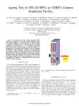
Part 1 (Divider A) : Axis Control Presentation
A presentation of the main components of the axis control system.
It describes the interactions between the various devices and the overall setup of an axis control application.
Part 2 (Divider B) : TSX AXM 172/182/162 Axis Control Modules
This part of the manual describes:
Application parameters,
Operating modes,
● Programming language syntax,
● Interaction between the axis control module and the PLC processor,
● Axis control module hardware installation.
●
●
Part 3 (Dividers C1, C2 and C3) : TXT L PL7 AXS V4 Axis Control Software
This part of the manual describes the axis control software for use with
TSX AXM 172/182/162 modules on FTX 507 workstations or IBM PS/2 or
compatible microcomputers.
Only the entry and modification of axis parameters and the AXM program are
covered here. The parameters and instructions are described in the axis
control module sections.
Part 4 (Divider D) : TSX XBT 182 Operator Terminal
A full description of the TSX XBT 182 operator terminal and its operating
modes.
Divider F contains the TSX AXM 172/182/162 module and TSX XBT 182
terminal Quick Reference Guides that summarize all essential information on
programming and operating TSX AXM 172/182/162 modules and their
terminals.
Divider G, Additional Information includes a procedure for updating
applications. This only applies to users with an installed base of axis control
applications running on V3 level PLCs (TSX 47-30/67-20/87-30) who wish to
upgrade their system to use V4 level Model 40 PLCs.
1/1
1
Presentation
1.2
Axis Control System Presentation
A
X
TSX Series 7 axis control system
T
AXM 182
Analog
Output
t
Zéro offse
or
F
OK
R2
R1
R0
In0
In1
In2
In3
In4
ALTIVAR 5
Speed
Controller
TSX AXM 182
or
T
FTX 507
††
AXIS
SELECT
TXT L PL7 AXS
AXIS
N°2
POS
ALARM
CLEAR
N
POS
ERROR
ALARM
STOP
STEP
M
NORMAL
CONFIDENTIEL
ALARM
ACQ
ALARM
DISPLAY
AXIS
X-
STOP
7
8
9
PROCESS
AXIS
HELP
CTRL
SPEED
TEACH
4
5
6
MODIF
INCR
DECR
X+
START
1
2
3
QUIT
FONCT
DEL
STOP
-
0
.
PROG
OUTPUT
X-
DIRECT
DRIVE
TSX XBT 172
CONFIGURATION
CYCLE
X+
ALARM
T
ENTER
TSX XBT 182
Incremental
Encoder
The TSX Series 7 axis control system comprises:
●
●
●
TSX AXM 172, TSX AXM 182 and TSX AXM 162 axis control modules for
use with TSX 47-40, TSX 67-40, TSX 87-40 and TSX 107-40 PLCs. These
programmable axis control modules run a user developed program and are
designed to control a speed controller used to move a moving part along
a linear axis with servo loop feedback control of its position.
The TXT L PL7 AXS V4 software pack for FTX 507 workstations. This
software is used to program TSX AXM 172, TSX AXM 182 and TSX AXM
162 modules. It also provides the user with ready to use Optional Function
Blocks (OFBs) that simplify the module set-up procedure.
The TSX XBT 182 terminal for operating and adjusting the modules.
The TSX AXM 172 and TSX AXM 182 modules can be programmed and can
operate independently of the CPU as compared with the TSX AXM 162 which
cannot be programmed. All movements are executed under the control of the
CPU.
The TXT L PL7 AXS V4 software is used in the application programming and
debug phases.
1/2
1
Presentation
1
A
Axis Control System Presentation
The TSX XBT 182 terminal provides all of the services required for normal
operation. It lets the user access all axes in a configuration. When required
by the user, it will also monitor motion, modify parameters, control manual
mode motion, etc.
There are two versions of the terminal:
● The TSX XBT 182.1 dedicated axis control operator terminal,
● The TSX XBT 182.2 multi-purpose terminal that provides a standard
operator dialog terminal function in addition to the specialized axis control
terminal features.
Companion products
In addition to TSX Series 7 products that are used for servo loop control and
processing, Telemecanique can also supply all of the other component parts
required in an axis control application (operating part) :
●
The XCC range of incremental rotational encoders (with an open collector,
Totem Pole or line transmitter output).
Refer to the general catalog or specialized catalog,
●
The Rectivar range of speed controllers for DC motors,
●
The MASAP range of servo drives, comprising :
●
●
An auto-synchronous permanent magnet (brushless) motor fitted with a
resolver,
A dedicated speed controller.
When used with TSX AXM 172/182/162 modules, these components let the
user develop high performance servo loop systems. Connection cables
between the TSX AXM modules and the MASAP servo drives are also
available. Refer to the general catalog or specialized catalog for more
information.
1/3
1
Presentation
1
A
Axis Control System Presentation
Multiple axis layout
Axis 0
Axis 1
T
AXIS
SELECT
ALARM
CLEAR
AXIS
N°2
N
POS
Axis n
POS
ERROR
ALARM
STOP
NORMAL
CONFIDENTIEL
ALARM
ACQ
ALARM
DISPLAY
AXIS
X-
STOP
X+
PROG
7
8
9
PROCESS
AXIS
HELP
CTRL
OUTPUT
INCR
DECR
FONCT
DEL
X-
DIRECT
DRIVE
TSX XBT 172
CONFIGURATION
STEP
SPEED
TEACH
4
5
6
MODIF
X+
START
1
2
3
QUIT
STOP
-
0
.
CYCLE
ALARM
ENTER
The TXT L PL7 AXS V4 (version 4.5) software allows up to 64 axis control
modules to be handled. The maximum number of modules physically present
in a configuration depends on the PLC used.
These modules can operate independently or can be synchronized by a PLC
program.
The TXT L PL7-AXS V4 software pack lets the user program all of the axis
control modules in a configuration.
Each module in a PLC rack slot is assigned an axis number from 0 to 63.
The TSX XBT 182 can access 16 modules and simultaneously display
positions on two axes.
Multiple application layout
TSX Series 7 PLC
Axis n
Axis 1
TSX AXM 182 Modules
Axis 0
Application 0
Application 1
Current
Application
Application m
Internal Memory
User Memory Field
For each axis, the user can generate up to nine applications.
Once generated, the applications stored in the PLC memory can be transferred
cycle by cycle to the internal memory of the axis control module via a
TSX XBT 182 terminal, the TXT L PL7 AXS V4 software or the user program
via the AXM LD OFB.
1/4
1
Presentation
1
A
1.3
Terminology Conventions
To simplify the descriptions in this manual, the following conventions are
used :
●
●
●
●
The term TSX AXM module refers to TSX AXM 172, TSX AXM 182 or TSX
AXM 162 modules, except in those sub-sections where their detailed
specifications are described.
(TSX AXM 172 and TSX AXM 182 modules have identical functions, only
their user interface and performance differ. The TSX AXM 162 has a user
interface identical to the TSX AXM 182 but cannot be programmed).
The term TSX XBT 182 refers to the operator terminal in either its dedicated
axis control version (TSX XBT 182.1) or its multi-function version
(TSX XBT 182.2).
The term PL7-AXE program or software refers to the program used to setup axis control applications on the FTX 507 workstation or an IBM PS/2 or
compatible microcomputer.
The term PLC Processor refers to Telemecanique TSX Series 7 Model 40
PLCs that accept axis control modules, i.e. (TSX 47-410/411/420,
TSX 67-410/420, TSX 87-410/420, TSX 107-410/420 PLCs).
1/5
A
1/6
2
Set-up Steps
2
A
The diagram below is intended to illustrate to the user the various steps that
are required when setting-up an axis control application and the order in
which it is recommended that these steps be performed.
By each step is listed the corresponding Sections or Sub-sections in this
manual and where necessary the type of form that should be used.
Assumption : PLC I/O already configured (using PL7-3)
Divider
Section
C2
1.1
B
B
D
7.1/7.2
7.3
1
A5-3
Parameter
table,
B
2
A5-1
Enter
configuration
C2
5
B
or C2
7.4
7.4
B
5
C2
6
B
C3
6
1 to 4
C2
D
7
3 to 7
C2
8 and 9
B
D
6
3 and 4
Install
PL7-AXE
Install
Hardware
Install modules,
Connection
(Terminal installation
Configure
Modules
Preliminary
adjustments
Preliminary checks
Adjust servo loop
Module
Programming
Sequential
PLC
Programming
Debug
From PL7-AXE
From XBT 182
Store
Documentation
Operation
With XBT
Without XBT
Write program,
Enter program
Form
A5-2
2/1
A
2/2
B
Contents
B
TSX AXM 172 / 182 / 162 Axis Control Modules
Section
Sub-Section
1 Module
Presentation
1.1 Axis Control Presentation
1.2 Particulars of TSX AXM 162 module
1.3 Internal Layout of the Modules
1.4 Servo Loop
1.5 Module I/O
1.6 Positioning Functions
Page
1/1
1/6
1/7
1/8
1/11
1/12
2 Configuration
Parameter Table
2.1 General
2.2 Parameter List
2/1
2/2
3 Operating Modes
3.1 Module Modes
3.2 Module and Axis Status
3.3 Safety Interlocks
3/1
3/4
3/5
4 Module Functions
4.1 Motion
4.2 Checks
4/1
4/5
5 Module Programming
TSX AXM 172 / 182
5.1 Language Presentation
5.2 Move Instructions
5/1
5/3
5.3 Move Organization Instructions
5.4 Data Control Instructions
5.5 Check Instructions
5.6 Examples
6 Dialog with the
PLC Processor
6.1 General
6.2 Integrating Axis Control into the
Sequential Program
6.3 Using the Interrupts
6.4 Full Module Control from
the PLC Processor
6.5 Discrete I/O and Register Interfaces
6.6 Access Conflicts
6.7 AXM 162 module : Move Programming
5/7
5/10
5/12
5/13
6/1
6/3
6/7
6/10
6/19
6/38
6/44
B/1
B
B
Contents
B
TSX AXM 172/182 Axis Control Modules
Section
Sub-Section
7 Setting into
Service
7.1 Location and Hardware Code
7.2 Identifying the Module
7.3 Connecting the Module
7.4 Preliminary Adjustments
7.5 Module Diagnostics
8 Specifications
8.1 Power Consumption
8.2 Input Characteristics
8.3 Output Characteristics
A Appendix
A.1 Determining Parameters
A.2 Servo Loop Performance
A.3 Glossary
A.4 Abbreviations
A.5 Configuration, Programming and Wiring Sheets
A.6 Index
A.7 Application Diagnostics Assistance
B
B/2
Page
7/1
7/2
7/3
7/14
7/21
8/1
8/1
8/4
A/1
A/9
A/10
A/12
A/14
A/19
A/20
1
Module Presentation
1.1
Axis Control Presentation
1
Purpose
TSX AXM 172, TSX AXM 182 and TSX AXM 162 Axis Control Modules are
part of the TSX Series 7 range of intelligent I/O modules.
These modules can operate independently and have their own microprocessor
and operating software providing high level performance and the ability to
control specialized applications.
These modules can control the motion of a moving part along a linear axis
with servo loop position control.
Inputs/Outputs
The module receives as an input an incremental position signal and signals
for reference point set-up (axis calibration) or event detection.
The output from the module is an analog signal used to control a servodrive.
Analog
Output ± 10V
AXM 172O
OK
R2
R1
R0
In0
In1
In2
In3
In4
X
T
ALTIVAR 5
M
Motor
Tachometer
T
Incremental
Encoder
TSX .7-40
The module also provides four auxiliary relay outputs.
Programming
TSX AXM 172 and TSX AXM182 modules have their own programming
language.
This language comprises a motion control instruction set and another
instruction set for structuring programs with jump and subroutine call
instructions.
The module program, or AXM program allows totally independent control of
simple or complex motion profiles.
The TSX AXM 162 module has no AXM program.
The module also exchanges data and can be synchronized with general
application sequencing through the I/O bus and the standard communications interfaces used between the module and the PLC processor. The part
of the PLC program dedicated to synchronization with the TSX AXM modules
is referred to as the PLC program.
1/1
B
1
Module Presentation
1
Axis Control Presentation
Main Characteristics
Inputs
B
Three inputs for incremental encoders:
• Open collector 5/24 VDC on TSX AXM 172,
• Line outputs (RS-422) on TSX AXM 182 / 162.
One 24 VDC (cam) event detector input.
One 24 VDC safety interlock input.
Compatible with Cenelec standard proximity
detectors.
One ± 10 V analog output for a speed controller.
Outputs
Four auxiliary relay outputs with one dedicated
to the speed controller safety interlock input.
Counting frequency
40 kHz max. for TSX AXM 172,
80 kHz max. for TSX AXM 182 / 162.
Servo loop
Proportional correction of deviation using
feed forward (overshoot) compensation.
Move
programming
• Specific motion control language for AXM
172 / 182:
254 program steps max.
32 basic instructions.
• From CPU for AXM 162.
Application rule
A trapezoid velocity rule is applied:
The ACCEleration and DECEleration
values can be modified.
Acceleration
ACCE
t
F
Velocity
DECE
t
X
Motion
t
1/2
1
Module Presentation
1
Axis Control Presentation
Adapting to Mechanical Characteristics
Given the maximum counter frequency accepted by the TSX AXM
modules, the movement limit characteristics depend on the selected
encoder and its resolution, defined as
the distance covered by the moving
part during one encoder pulse.
Encoder Pulses
In0
B
In1
Maximum allowed encoder frequencies:
• TSX AXM 172 module :
40 kHz,
• TSX AXM 182 / 162 modules : 80 kHz.
The TSX AXM 182 / 162 modules have a "multiply by 4" feature that allows:
- Improving the sensor resolution by a factor of 4 with a given type of encoder,
or
- Selection of an encoder that has 4 times less resolution when the resolution
value is set.
In the Appendix Section (refer to Appendix pages A/5 and A/6) two tables
“TSX AXM 172 / 182 / 162 module performance” summarize the maximum
axis characteristics (length, velocity, etc).
A validity check on the values is provided by PL7-AXE during the definition
of machine parameters.
The table below illustrates the differences between the three types of
module :
Input interface
Programmable
Non programmable
Open collector
RS 485
TSX AXM 172
TSX AXM 182
TSX AXM 162
1/3
1
1
Module Presentation
Axis Control Presentation
TSX AXM 172 module hardware presentation
The TSX AXM 172 is a single height module comprising the following
parts:
1 A protective enclosure.
1
B
6
2
AXM 17 O
OK
R2
R1
R0
In0
In1
In2
In3
In4
3
7
2
2 10 indicator LEDs:
(F)Module failure,
OK module power on and operating correctly,
R0 to R2 relay outputs active,
In0 to In4 inputs at 1.
3 A connector for the module analog
output.
4 A connector for all encoder inputs
to the module and the four relay
outputs.
5 A removable TSX BLK 4 terminal
block with 32 screw terminals
available for connection.
4
6 A 9-pin TSX CAC 04 Sub-D connector.
5
7 An adjustment potentiometer for
the analog output offset level.
Notes:
• The status of relay output R3 is not displayed,
• The TSX BLK 4 terminal block and the TSX CAC 04 connector are not
supplied with the module but are absolutely necessary for using the module.
For safety reasons, never replace the TSX CAC 04 connector with a similar
connector.
7
2
9
1/4
The software and hardware
configuration code is 729.
1
1
Module Presentation
Axis Control Presentation
TSX AXM 182 / 162 module hardware presentation
The TSX AXM 182 / 162 is a single height module comprising the following
parts:
1 A protective enclosure.
1
2
AXM 18
tput
Ou
Analog
3
7
4
5
fset
Zéro of
F
OK
R2
R1
R0
In0
In1
In2
In3
In4
B
2 10 indicator LEDs:
2
(F)Module failure,
OK module power on and operating correctly,
R0 to R2 relay outputs active,
In0 to In4 inputs at 1.
3 A connector for the module analog
6
output.
4 A connector for module auxiliary
I/O connections and their supply
lines.
5 A connector for encoder connection.
6 A connection kit comprising three
Sub-D connectors that must be
ordered
separately.
Ref.
TSX CAC 06.
7 An adjustment potentiometer for the analog output offset level.
8 A 25-pin Sub-D connector for connecting the incremental encoder.
Note:
Connections must be made using the TSX CAC 06 connection kit or
VY1-M621-CLC5 and VY1-M621-CLA cables.
7
3
2
The software and hardware configuration
code is:
TSX AXM 182 : 732
TSX AXM 162 : 735.
1/5
1
Module Presentation
1.2
Particulars of the TSX AXM 162 module
1
The TSX AXM 162 module is similar to the TSX AXM 182 module. Its
difference lies in the fact that it does not have an “Automatic” mode (or
program).
As this manual is common to all three modules, TSX AXM 172 / AXM 182 /
AXM 162, it is therefore necessary to explain the significance of the lack of
automatic mode. Section 5 "PROGRAMMING" does not concern the TSX
AXM 162 module. On the other hand, paragraph 6.7 is entirely dedicated to
programming moves from the CPU of the programmable controller.
B
In the rest of this document, so as to avoid reading parts unnecessarily, text
which is not relevant to the TSX AXM 162 is highlighted in grey and a note
is given at the bottom of the page.
List of functions not available on this module
- Automatic or program mode (cycle, point to point, step by step).
- Teaching of set points and consequently everything which concerns the
internal set points table (WNi table).
- Fault processing by module program.
1/6
1
Module Presentation
1.3
Internal Layout of the Modules
Application
InØ
In1
In2
Reference
set-up
A
B
ALTIVAR 5
Servo
Loop
24V
24VDC
24VDC
24V
Configuration
Parameters
AXM
Program
Speed
Controller
Enable
Speed controller
PLC
Processor
TSX AXM Module
Incremental
Encoder
T
1
B
Interface
I/O
IW / OW
XBT
RØ
R1
R2
R3
In3
Aux.
I/O
Internal
Variables
In4
The TSX AXM modules incorporate five main functions:
• Moving part position servo control,
• Processing of the application programmed by the user,
• Operating functions,
• Interface with the application,
• Interface between the PLC processor and the TSX XBT terminal.
Servo position control
Depending on the position and velocity instructions and on the actual position
of the moving part, the module generates the velocity command for the speed
controller.
Application processing
The configuration parameter table adapts module operation to the application to be processed.
The module executes the AXM program entered by the user and derives the
target positions and the motion velocities.
Operating functions (not shown in the diagram)
The internal software of the module supports a set of functions and checks
that apply to module operation:
• Manual mode motion, manual reference set-up, etc.
• Deviation and stop checks, etc.
Application interface
This part comprises the module I/O described in Sub-section 1.4.
Interface between the PLC processor and the TSX XBT terminals
This function enables synchronization of the TSX AXM application with that
of the PLC processor. Communication is “user transparent” when a
TSX XBT terminal is used to control the module.
Functions not available on TSX AXM 162 module.
1/7
1
Module Presentation
1.4
Servo Loop
Main servo loop function
The servo loop is designed to link the position of a moving part to an
instruction value.
B
As in all servo controlled components, static and dynamic components are
dependent on the complete motion system (including both the algorithm and
mechanical parts) and on the variation of the instruction over time.
Machine layout
Module
Axis
Speed
Controller
Motor
A
Reduction
AXM
B
Pitch
C
Vl
Tachometer
Generator
F
Incremental
encoder
Pitch = distance covered in a single shaft revolution.
The incremental encoder can be either linear or rotary. In both cases it
provides a signal with a frequency proportional to the velocity and a number
of pulses that is proportional to the position.
Depending on the layout of the machine system, the sensor can be fitted in
A, B or C positions (rotary in A and B, linear in C).
1/8
E
1
Module Presentation
Servo Loop
Diagram
vref
KV
Analog
Output
V
e
Reference
Set-up
+
eref
KVAR
+
-
ACCEL DECEL
Scaling
+
Peak
Limiting
Upcounter
Downcounter
B
DAC
Encoder
Inputs
Reference set-up
This function is not accessible by the user. It is used to enter the instruction
values for eref = f(t) and vref = f(t) as a function of the overshoot and velocity
values specified by the user along with the acceleration (ACCEL) and
deceleration (DECEL) values set in the configuration and the velocity
modulation factor.
Scaling
Depending on the maximum velocity, distance and resolution, the module
calculates the value of the scaling factor KR (that is also referred to as the
machine characteristic factor).
The user can access a fine adjustment of this factor from the TSX XBT
terminal or PL7-AXE program to compensate for any lack of precision in the
machine parameters entered in the configuration.
Upcounter/Downcounter
The sum of the sensor increments gives the position of the moving object and
allows monitoring of its motion.
1/9
E
1
Module Presentation
1
Servo Loop
KVAR
Proportional gain factor:
KVAR = C . KPOS . UMAX
B
C
: Constant
UMAX : The value of the variable speed controller instruction corresponding
to VMAX velocity (UMAX < 9 V).
The user enters the required KPOS value in the configuration and the module
calculates the corresponding KVAR value.
Peak Limiting
The LIMV factor entered in the configuration allows the user to adjust the
authorized velocity overrun value.
5% < LIMV < 20% of VMAX
KV
The feed forward factor or overshoot compensation factor is expressed as a
percentage. 100% corresponds to the value that would completely remove
any deviation at constant velocity when using a speed controller without
continuous error.
When KV increases, the deviation decreases, however the risk of an overrun
including the risk of stop point overshoot is increased. Therefore a compromise between the two must be found.
Note: In some cases, the deviation passes through a minimum level and may
change sign when KV increases.
Digital Analog Converter (DAC)
The function of this circuit is to convert the digital output value (10 bits + sign)
into an analog voltage of between +10 V and -10 V.
Sampling Rate
Although not shown by the diagram, the servo loop operates with a sampling
rate of 10 ms.
1/10
1
Module Presentation
1.5
Module I/O
1
Inputs
TSX AXM modules have five inputs In0, In1, In2, In3, In4.
In0, In1, In2: Incremental encoder inputs
These three inputs are designed to receive an incremental type position
signal.
Various sensors can be used, such as:
Rotary incremental encoder,
• Linear incremental encoders.
• signals from a MASAP variable speed controller.
•
In0 and In1 are designed to receive signals from a direction discriminator
encoder.
In2 is designed to receive the zero marker signal from the incremental
encoder.
In3: Event detection input
A 24V input designed to receive a signal from a position sensor when used
with mechanical cam detection:
• For manual reference point set-up (determining the physical reference point),
• For motion with event sensing.
In4: Safety interlock input
The safety interlock input that must be kept supplied. When there is no
voltage on this input, an emergency stop is caused on the axis.
Outputs
The module comprises one analog output and four relay outputs.
An analog output, ± 10V (10 bits + sign for TSX AXM 172 and 12 bits + sign
for TSX AXM 182 / 162) designed for controlling a variable speed controller.
R0: Relay output designed to control the speed controller safety interlock
input.
Relay R0 is controlled by the module. The analog output takes its value
200ms after the relay is enabled.
R1, R2, R3: Auxiliary relay outputs
These three outputs can be enabled by instructions from the AXM program
and can be used for direct action on the application. These outputs can also
be enabled by discrete I/O interface bits or by the TSX XBT terminal in other
operating modes.
Note
The I/O connection and technical characteristics are described in Subsections 7.3, 8.2 and 8.3.
Functions not available on TSX AXM 162 module.
1/11
B
1
Module Presentation
1.6
Positioning Functions
1
Position reference
Point Field
L MIN
B
PRF
L MAX
Index Position
Absolute Position
0
X MIN
Machine Origin
Valid Measurement Field
X MAX
Position calculation
The module generates the position measurement by counting the number of
pulses received from an incremental encoder.
Position reference
Axis positions are given in relation to the reference point. The module enables
the use of various reference point set-up procedures.
Point field
The field that comprises all measurement points is restricted only by the
counting capacity and the resolution of the selected sensor.
Travel limit
By configuration, the user defines two travel limit positions referred to as soft
stops (XMIN and XMAX). Axis or moving part motion is restricted to the distance
between the two limits. This is the valid measurement field. The module will
systematically stop the moving part if it moves outsid the soft stops.
Indexed positions
The moving part position can be referenced in relation to the PRF parameter
(position index).
Functions not available on TSX AXM 162 module.
1/12
1
Module Presentation
1
Positioning Functions
Various accessible positions
Velocity/Time presentation
Velocity/Position presentation
B
Velocity
Velocity
1000 mm/mn
1000 mm/mn
300 mm/mn
300 mm/mn
0
200 mm/mn
Time
0
200 mm/mn
Position
These two presentations illustrate actual moving part motion. The Velocity/
Position presentation has the advantage of showing both useful parameters
in the same graph. The other graph showing Velocity/Time will be used later
in this manual. To simplify the illustration of motion with acceleration
and deceleration periods, line segments will be used and not curves.
Negative velocities indicate reverse direction motion.
Positions
The module can process the following types of position:
•
•
•
Immediate positions: positions where the value is given explicitly in the
instruction,
WNi internal positions (numbers 0 to 100): internal words designed to
receive the positions obtained by teaching the module set points or by
entering instructions,
External positions provided by the TSX XBT terminal or by the PLC
processor using register words OWxy,6 and OWxy,7.
Measurement units
The position, velocity and acceleration measurement units are physical units:
User defined physical units
The user defines the configuration parameters (refer to Sub-section 2.2), the
physical units for the display of the measurement values by PL7-AXE and the
TSX XBT terminal.
Module physical units
These are calculation units used by the module and the display units used for
the measurement values in register words OWxy,4 to 7 and IWxy,6 and 7.
They depend on the maximum velocity VMAX selected (remember that
VMAX depends on the resolution, refer to the complete table given in the
Appendix).
Functions not available on TSX AXM 162 module.
1/13
B
1/14
2
Configuration Parameter Table
2.1
General
2
Purpose
A table of 32 parameters enables the adaptation of module operation to the
application to be processed.
There are three types of parameters:
B
Axis parameters (sensor resolution, maximum velocity, etc.),
● Servo loop parameters (position gain, etc.),
● Operating parameters (error detection and processing, etc.).
●
The module can only operate if this table has been filled-in and transferred
to the internal memory by the user.
Parameter access
These parameters must be entered using PL7-AXE in Configuration Mode.
Once the module has been configured, some of the parameters can also be
modified :
●
●
From a TSX XBT terminal,
By AXM program instructions.
Access to modifications depends on the type of parameters selected:
A : Accessible only using PL7-AXE,
B : Can be modified using the TSX XBT terminal,
C : Can be modified using the TSX XBT terminal and AXM program
instructions.
Selecting parameter values
When using PL7-AXE to enter the parameter table in Configuration Mode,
once the resolution and maximum velocity parameters have been entered,
default values are proposed for other parameters.
These parameters must be appropriate for the application.
The table on the following page is designed to guide the user in selecting the
values of these parameters.
Functions not available on TSX AXM 162 module.
2/1
2
Configuration Parameter Table
2.2
Parameter List
2
The table below gives the function of each parameter along with its possible values.
Parameters Explanations and limit values
B
Sensor
resolution
RESOL
Distance travelled by the moving part between
two sensor points (1 increment) See Appendix A.1.
Maximum
velocity
VMAX
Max. moving part velocity by applying the value UMAX
velocity to the analogue output. See Appendix A.1
Type
Typical
values
A
Min. limit : TSX AXM 172: 0.1 µm Max. limit: 1000.0 µm
TSX AXM 182: 1 µm.
A
Min. limit : 11 mm/mn
Max. limit : Value calculated by PL7-AXE, depending
on the resolution of the selected sensor.
User
selected
units:
UPUL
UPUV
UPUA
Soft
stops
XMAX
XMIN
Display units for all parameters, as opposed to the
module units that are used for internal calculations.
Length unit
: µm, mm, cm, dm, m
Velocity unit
: mm/mn, cm/mn, dm/mn, m/mn
Acceleration unit : mm/s2, cm/s2, dm/s2, m/s2
Valid measurement field
Limits :
Acceleration
Deceleration
ACCE
Limits :
DECE
Type of
reference
TYPEREF
Manual
drive
velocity
VMAN
“Stopped”
velocity
VSTOP
2/2
A
See Section 4.2
A
The limit values are calculated by
PL7-AXE depending on the resolution
and maximum velocity.
See Section 4.1
C
The limit values are calculated by
PL7-AXE depending on the resolution
and maximum velocity.
See Section 4.1
Values :
mm
mm/mn
mm/s2
VMAX/6
B
1 = short cam + zero marker
2 = cam
3 = long cam and limit switch + zero marker
This is the velocity of the moving part in assisted
man. mode, man. drive mode and man. set mode.
Min. limit: 1 mm/mn,
Max. limit: VMAX.
See Section 4.2
Min. limit: 1 mm/mn,
B
VMAX/10
C
Max. limit: VMAX.
VMAX/10
2
Configuration Parameter Table
2
Parameter List
Parameters Explanations and limit values
Stop time
period
TSTOP
Target
window
TW
Max.
deviation
DMAX
See Section 4.2
Min. limit: 1 x 10ms,
Type
B
Max. limit: 65535 x 10 ms.
C
See Section 4.2 (Target Window Check).
Min. limit: 1 µm,
Max. limit: (XMAX-XMIN)/10.
See Section 4.2
Min. limit: 1 µm.
C
Max. limit: (XMAX-XMIN)/2.
B
Position
loop
KPOS
LIMV
KV
B
Refer to appendix A2
9
Position gain
: 1.00 to 32.00 s-1
Max. velocity tolerance : 5 to 20% over VMAX
Velocity correction factor : 0 to 100%
Deviation
check
MDMAX
Divert mask:
NDMAX
Divert step number: 0 to 253.
16
20%
20%
See Section 4.2
Y = Fault process. by XBT or PLC,
N = On error, divert AXM program
to divert step NDMAX.
Stop
check
MSTOP
Divert mask:
NSTOP
Divert step number: 0 to 253.
NTW
B
1 sec
Speed
Analog output voltage corresponding to max.
controller
velocity VMAX. Refer to appendix A1.
voltage for
VMAX /UMAX Min. limit: 1 volt,
Max. limit: 9 volts.
Target
window
checks
MTW
Typical
values
B
Y
C
See Section 4.2
Y = Fault process. by XBT or PLC,
N = On error, divert AXM program
to divert step NSTOP.
B
Y
C
See Section 4.2
Divert mask:
Y = Fault process. by XBT or PLC,
N = On error, divert AXM program
to divert step NTW.
Divert step number: 0 to 253.
B
Y
C
Functions not available on TSX AXM 162 module.
2/3
2
Configuration Parameter Table
2
Parameter List
Parameters Explanations and limit values
Type
B
Sync. timeout period
TSYN
See Section 4.2
Synchronization time-out:
Min. limit: 1 x 10ms,
Max. limit: 65535 x 10 ms.
B
MSYN
Divert mask: Y = Error processed by XBT or PLC,
N = On error, divert AXM program
to NSYN divert step.
B
NSYN
Divert step number: 0 to 253.
C
PLC
processor
checks
MCPUF
Typical
values
Y
See Section 4.2
Divert mask: Y = Error processed by XBT or PLC,
N = On error, divert AXM program
to NCPUF divert step.
B
NCPUF
Divert step number: 0 to 253.
C
Number of
internal
positions
Min. limit: 0,
A
Max. limit: 100.
Y
0
NBWN (*)
(*) The AXM program can use a maximum of 100 WNi internal positions.
The NBWN parameter determines the number of WNi internal positions numbered from WN0 that
will be transferred when the application is stored in the internal memory of the PLC or saved to disk.
Functions not available on TSX AXM 162 module.
2/4
3
Operating Modes
3
Important Note
Most of the operations described in this Section can be performed from three
different systems.
●
●
●
PL7-AXE which in addition to its configuration/programming function also
allows the user to debug applications,
A TSX XBT terminal,
The user program (PLC program) via the PLC/TSX AXM module interface.
For a given operation, the procedure that applies varies depending on
which system the user wishes to use.
Rather than describe each operation three times, once for each system, the
general procedure for each operation will be described. It is then up to the
user to refer to the appropriate Section for the system to be used.
The user can refer to:
Sub-section 6.4, that describes the interface between the user program and
the module,
● Divider C2, Section 7 that describes PL7-AXE debug functions,
● Divider D, Section 3 that describes TSX XBT terminal functions.
●
3/1
B
3
Operating Modes
3.1
Module Modes
3
The module can control the motion of a moving part in five operating modes:
● Automatic,
● Manual reference set-up,
● Manual operation under visual control,
● Assisted manual operation,
● Servo loop disabled.
B
All of these modes can be selected from the TSX XBT terminal (or by a
register word). However, an operating mode can only be selected when the
moving part is stopped. If motion is in progress (or if the moving part is not
declared as stopped), the Start command will be ignored by the module.
Once the mode and the associated parameter(s) have been selected, the
Start command starts mode execution, the mode is enabled. The Stop
command stops mode execution, the mode is disabled.
Selecting another mode when the currently selected mode is enabled will
disable it.
Note: When the modes are controlled by the PLC program (by OW register word
bits), execution can only be started when the mode is effectively selected by
the module : identity between the selected mode and the information
returned by the module and presence of the activation wait bit.
Automatic mode (or programmed mode)
The AXM program generated by the user and stored in the internal memory
of the module automatically controls motion of the moving part.
This mode has three sub modes:
●
Automatic cycle: The program is executed until the end of program
instruction (END). This is the standard operating mode.
Automatic step-by-step: After each program step is executed, the moving
part is stopped and the module awaits a resume command. This mode is
useful for debugging a program.
● Automatic point to point: the program is executed in sequence until an
instruction with a stop order is reached, the module then waits for a restart
command. This mode is useful for debugging an application.
Procedure:
● Select the sub-mode,
● Start mode: The moving part executes the trajectories defined by the AXM
program.
●
Manual reference set-up mode
The user determines the direction of motion. The velocity of the moving part
or axis feedrate is defined in the configuration using VMAN: manual velocity.
The moving part automatically sets its reference point from a cam, depending
on the type of reference point set-up selected (refer to Sub-section 4.1). This
mode enables the axis to be referenced.
Note : The reference point can be set-up automatically using an instruction. This can be
difficult to perform if the position of the moving part is not known precisely by the
module (resulting in motion away from the cam, for example). A type 3 reference setup (long cam at end of travel) can be used to avoid this risk.
Functions not available on TSX AXM 162 module
3/2
B
3
3
Operating Modes
Module Modes
Procedure:
● Select the mode,
● Enter the reference point,
● Start the mode: The moving part moves towards the target position and
stops (the Start command is implicit when using a TSX XBT terminal).
Manual control mode
Moving part motion and stopping are directly controlled by the user who can
see the axis and moving part. The velocity of the moving part (VMAN
parameter) is specified in the configuration. This mode is used to position the
moving part during application debug phases.
Procedure:
Select the mode,
● Enter the direction of motion,
● Start the mode: The moving part starts to move in the selected direction,
● Stop the mode: Stops the moving part, (The Start and Stop commands are
implicit when using a TSX XBT terminal).
●
Note: For safety reasons, authorized motion is restricted to:
● XMAX - 2 x TW in the positive direction,
● XMIN + 2 x TW in the negative direction.
Assisted manual mode
The user enters the target position for the moving part. Moving part velocity
is specified in the configuration by the VMAN parameter: Manual velocity.
This mode is used to position the moving part during application debug steps.
It can also be the primary operating mode in applications with basic motions.
Procedure:
Select the mode,
● Enter the target position,
● Start the mode: The moving part moves to the target position and stops.
This is the preferred operating mode for the TSX AXM 162 module.
●
Servo loop disabled (open loop)
The module directly controls the analog output on open loop, i.e. the servo
loop is disabled. This mode is used to analyze axis operation separately from
the position control servo loop (e.g. for machine system adjustment).
Procedure:
Select the mode,
● Enter the velocity of the moving part:
●
Module
TSX AXM 172
TSX AXM 182 / 162
TSX XBT 182
-1023/ +1023 x 10 mV -1023/ +1023 x 10 mV
PL7-AXE Debug Mode
-1023/ +1023 x 10 mV -4096/ +4096 x 2.5 mV
●
●
Start the mode: The moving part moves in the specified direction at the
specified velocity (with the ability to change the speed reference),
Stop the mode: Returns the analog output level to 0 (causing return by
gentle deceleration).
3/3
B
3
Operating Modes
3.2
Module and Axis Status
3
Module status
When the module is operating without any faults, three module conditions can
be defined :
●
B
●
●
Module not configured
No configuration parameter has been sent to the module and the module
cannot control any motion. A PL7-AXE configuration must be loaded before
any other operation is performed.
Module configured and stopped
A module state that enables the modification or the transfer of the configuration and the AXM program. In this state, the module cannot perform any
motion, but it will however continue to calculate moving part position.
Module configured and running
In this state, the module is fully operational.
The module is stopped or started using a TSX XBT 182 terminal, a microcomputer running PL7-AXE or the PLC program through register or command
words. When a PLC error (*) is present, it is indicated by the Fail LED being
lit or the OK LED being extinguished. The status bit Ixy,S is also set to 1.
Regardless of the cause of the error, the module is forced to stop.
(*) This applies to errors effecting the module itself and not application errors,
described in Sub-section 4.2.
Axis status
Programmed axis
An AXM program must be loaded in the module with PL7-AXE (or from the
PLC program using the AXM LD OFB).
Referenced axis
The axis has been referenced using one of the reference set-up procedures
(refer to Sub-section 4.1).
The following table gives the different operating modes that can be accessed
in each of the four states.
Axis state
Accessible modes
Programmed and
referenced
All operating modes can be accessed
Programmed but
not referenced
Manual reference point set-up and automatic mode
if the first motion instruction is an automatic reference
point set-up command
Not programmed
but referenced
All operating modes can be accessed except for
automatic mode
Not programmed
not referenced
Manual reference point set-up
Note : Forced reference set-up also enables the axis to be referenced (see Sub-section 4.1).
Functions not available on TSX AXM 162 module
3/4
B
3
Operating Modes
3.3
Safety Interlocks
3
Application safety interlocks
Input In4: Must have a 24 V supply. When this input is no longer supplied, an
emergency stop error is caused. This stops the moving part, disables relay
R0 and the currently selected mode.
This mode can be used as a safety interlock to ensure that the module can
only operate when the speed controller is operational.
Relay output R0: This output is designed to control the speed controller
enable input. Relay R0 is activated by the module as soon as the module
starts running. It is immediately disabled if a module error occurs.
PLC safety interlock
The Emergency Stop bit: Bit Oxy,7 must be set to 1 by the PLC program or
by the TSX XBT terminal.
Therefore, when this bit goes to 0, it causes an emergency stop fault:
● Stopping the moving part,
● Disabling relay R0,
● Disabling the currently selected operating mode.
Interlock On and Interlock Off modes
Interlock On:
If this is selected, a PLC error or stopping the PLC will stop the moving part
and disable the currently selected module operating mode (PLC (CPU) error
condition).
Interlock Off:
If this is selected, it allows the module to operate independently.
The safety interlock can be switched Off in Debug mode, allowing the module
to operate with the PLC stopped, without causing a PLC (CPU) error.
The safety interlock can be selected through the TSX XBT terminal (Function
F85) or by bit OWxy,0,E (1 = Interlock Off).
3/5
B
B
3/6
4
Module Functions
4.1
Motion
4
Motion functions performed by the module
In addition to the moving part motion commands, the module also performs
other specific functions that cause motion. The table below shows the modes
where these functions are available:
Mode:
Function
Reference
set-up
Automatic
Manual
Ref. Set-up
Manual
Drive
Assisted
Manual
Servo
Off
Yes
Yes
No
No
No
Forced
ref. set-up
Module stopped, no errors
Teaching
set points
Moving part stopped, axis referenced, no errors
Return from
overshoot
Enabled after soft stop overshoot by the
moving part and fault is acknowledged
B
No (*)
(*) Except for TSX XBT Function F95.
Motion
All motion commanded by the module (except when the servo loop is
disabled) follows the velocity and acceleration rules shown below:
The internal module software generates a series
of position instructions corresponding to the motion to be performed:
Acceleration
ACCEL
t
(1) Increase velocity according to the acceleration
defined in the configuration,
(2) Constant velocity motion with the velocity set
by instruction or by configuration
(in manual modes),
(3) Deceleration with the parameters set in the
configuration,
Velocity
DECEL
F
t
Motion
(1)
X
(2)
(3)
(4)
t
(4) Stop at a target position.
Functions not available on TSX AXM 162 module
4/1
4
Module Functions
4
Motion
B
Attention:
● A motion command can only be executed if the axis is referenced. This still
applies when the servo loop is disabled.
● Moving part stoppage is effectively declared only after the TSTOP time-out
set in the configuration.
Velocity correction factor
The user has access (through the TSX XBT terminal or command register
word) to a velocity correction factor that enables all velocity values to be
multiplied by a factor of 0 to 2 in increments of 1/100 (TSX AXM 172) or 1/1000
(TSX AXM 182 / 162).
Program-
Special cases:
med
● Motion with stop on target :
velocity
If the programmed or configured
velocity cannot be reached during
the motion command (distance too
short), the module calculates the
distance required for deceleration
to the target point and automati- Velocity
cally starts to decelerate once the
minimum distance is reached. If
the deceleration distance as
entered is too short, the module
rejects the command and stops the
moving part.
●
●
Motion without stop :
If the motion command to be
performed is impossible with the
various parameters defined :
acceleration, deceleration, target
position, programmed (or configured) velocity, velocity correction
factor, the module rejects the
command and stops the moving part.
Target position
Velocity
A
A' B
Target position
Other cases of command rejection :
● When two single step motion commands are programmed in opposite
directions as a continuous move without allowing for motion reversal,
● When a motion command is given for a non-referenced axis.
Functions not available on TSX AXM 162 module
4/2
Target position
4
Module Functions
4
Motion
Reference set-up
Reminder: An incremental encoder does not provide a position measurement, only a number of pulses proportional to the distance travelled. For this
distance to indicate a position, a reference point must be set-up (usually = 0).
This operation is the reference set-up. This allows the module to generate
absolute position measurements using the incremental encoder. The reference set-up command is initiated by an AXM program command: SRP+ or
SRP- or by a manual reference set-up command. The reference set-up
procedure is identical in both directions. The module has two inputs that are
used for reference set-up (IN2 for the zero marker and In3 for a cam) and 3
types of detection.
Type 1:
Type 2:
Type 3:
Short cam (the cam signal is only present for a single zero marker
pulse) and zero marker, the reference point is indicated by the cam
presence signal on In3 and an edge on In2 (rising or falling) (see
next page),
Cam: The reference point is indicated by an edge on In3 (rising or
falling) (see next page),
Long cam and limit switch (the cam signal is present for a number
of zero marker pulses) and the zero marker.
The reference is indicated in the same way as type 1.
Functions not available on TSX AXM 162 module
4/3
B
4
Module Functions
4
Motion
General description of the different phases of reference point set-up:
➀ Moving part motion at the programmed approach velocity or
VMAN, until the reference point is
Velocity
1
reached,
V
B
➁ Stop
the moving part when the
reference point is sensed,
➂ Return
the moving part at Low
Velocity (1) until the reference
point is reached,
2
0
Start
PV
4
3
➃ Load the external position EXT in
the position measurement counter
and stop the moving part.
In reverse motion, the reference point set-up procedure is similar and its
representation is symmetrical.
(1) Low Velocity (PV) is set to 1/8th of the approach speed for TSX AXM 172
modules and 1/16th of the approach speed for TSX AXM 182 / 162 modules.
The cam can be located in a position (called reference position PREF) other
than the reference point. The offset value between machine reference and
the reference point cam must be loaded in the external position register EXT.
Note:
Type 3 operates differently (see table below and description on next page).
Detailed description of each type of reference set-up
Off cam start
On cam start
Type
+ Direct.
- Direct.
+ direct.
- direct.
Type 1
Motion
Zero Marker
Cam
In2
(1)
(2)
(2)
(1)
(1)
(1)
(1)
In3
Type 2
Motion
Cam
(1)
In3
(1)
(2)
(2)
(1)
Type 3
Motion
Zero Marker
In2
Cam
In3
(1) For type 1 and 2 reference set-ups, move the moving part away from the
cam before referencing.
4/4
B
4
Module Functions
4
Motion
Type 3 special case
● Moving part stop in phase ➃ is commanded when the cam is no longer
present (falling edge on In3),
● On cam: The direction of motion is the opposite of that requested and
moving part stop in phase ➁ is commanded when the cam is no longer
present (falling edge on In3).
Forced reference point set-up
This is used to reference the axis without moving part motion.
Procedure:
The moving part is stopped and no errors are present,
● Measure the moving part position in relation to the machine reference point,
● Load the measurement value in the external position register (PREF) or use
the TSX XBT terminal,
● Forced reference set-up command: the current position measurement
counter takes the loaded value.
●
Teaching set points
The set point teaching function enables the acquisition of set points by the
module memory, by successively moving the moving part to the different
positions to be stored.
These positions are stored in the WNi internal words. Up to 100 can be stored.
Procedure:
● Move the moving part to the position to be stored,
● Select the internal position number,
● Enter the Teach command.
The moving part must be stopped when the teach command is sent.
Note: The values of the WNi positions can also be set by AXM program,
TSX XBT terminal or PL7-AXE instructions.
Return from soft stops
After the moving part overshoots the upper or lower travel stops called soft
stops, this command is used to automatically return it within the permitted
movement field:
●
●
In + direction, the moving part is located at point XMAX + 2 x TW,
In - direction, the moving part is located at point XMIN - 2 x TW.
Procedure:
● Error acknowledgment,
● Return from soft stop overshoot (backoff).
Functions not available on TSX AXM 162 module
4/5
B
4
Module Functions
4.2
Checks
4
Purpose
The check function is essential in position control applications due to moving
part motion and the risks involved.
The checks are carried out internally and automatically by the module.
By default, all checks are enabled (module running). Some of these checks
can however be disabled by AXM program instruction. The user can select
the parameters assigned to the checks, to adapt them to the particular
application.
These checks are used to detect moving part positioning errors, trajectory
deviation errors or module and PLC errors.
B
Principle
Two types of checks are defined depending on the seriousness of the
detected error:
●
1st. type: Detection of this type of error systematically quits the current
operating mode.
List of type 1 checks:
● Soft stops (only operate if the axis is referenced),
● Disable the servo loop,
● PLC power supply error,
● Terminal block unlocked.
This type of check remains enabled regardless of the selected operating
mode and causes:
● Error indication,
● Disable the servo loop,
● Decelerate until DAC instruction value equals 0,
● Disable the speed controller interlock relay R0,
● Quit the mode (disable),
● Await acknowledgment.
●
2nd. type: Detection of this type of error does not systematically quit the
current operating mode.
List of type 2 checks:
Mode
Position
error
Target
window
Stop
Synchro- Emergency CPUF
nization
stop(*)
error
Automatic
Yes
Yes
Yes
Yes(**)
Yes
Yes
Manual ref.
Yes
No
Yes
No
Yes
Yes
Manual
Yes
No
Yes
No
Yes
Yes
Assisted man.
Yes
Yes
Yes
No
Yes
Yes
Open loop
No
No
No
No
Yes
Yes
(*) The emergency stop cannot be processed by the AXM program,
(**) This check is disabled in the step-by-step or point-to point sub-modes.
Functions not available on TSX AXM 162 module
4/6
B
4
Module Functions
4
Checks
This type of error can be processed in two different ways. The selection is
made in the software parameter configuration table, for each check with the
divert mask parameter.
●
●
With operator intervention (Divert mask = Yes):
● Error indication,
● Decelerate until DAC instruction = 0,
● Disable the speed controller interlock relay R0,
● Wait for a resume command or quit the current mode. During this
waiting phase, the servo loop is disabled.
With an AXM program divert sequence (Divert mask = No):
(only in automatic mode)
● Disable the check,
● Divert to the program step defined in the configuration.
It is advisable to start a divert program with a Stop instruction to stop the
motion where an error was detected.
It is necessary to enable the checks with the SCTL instruction, if checks will
be required again.
The stop, position error, synchronization, target window and CPUF checks
can be disabled by the RCTL instruction (refer to Sub-section 5.4).
Note:
The Emergency Stop error cannot be inhibited or processed by a divert
step.
The flow chart below provides a summary of the possible processing of type
2 errors:
Type 2 error
Automatic
mode
enabled
Yes
Yes
No
Check
inhibited by
instruction
- Indication
- Deceleration
- R0 inhibited
No
Error not
detected
Divert mask
No
Divert AXM
pgm. or divert
step
Yes
End of
error and
DAC=0
Yes
No
Resume
command
No
Yes
Ack. error,
resume current
mode
Abort
command
No
Yes
Ack. error,
quit current
mode
Functions not available on TSX AXM 162 module
4/7
B
4
Module Functions
4
Checks
Parameters linked to the checks
The parameters linked to the checks must be defined in the configuration
parameter table. Some of these parameters can be modified by the TSX XBT
terminal and/or by the AXM program.
B
Soft stop checks (type 1)
The module checks that the position of the moving part remains within the two
limit values XMIN (lower soft stop) and XMAX (higher soft stop). This check
is enabled as soon as the axis is referenced. The return from soft stop
overshoot command (backoff) allows the moving part to be automatically
repositioned within the valid measurement field. After acknowledgment,
return from overshoot is performed with the servo loop open.
Return velocity is calculated from the deceleration factor
DECEL: V = DECEL/100 (V in mm/s and DECEL in mm/s2).
Calculation capacity overflow check (type 1)
The module checks to ensure that when a calculation is made it does not
exceed the calculation capacity. The capacity level depends on the resolution
selected and is set slightly above the maximum soft stop values accepted by
PL7-AXE. This type of error causes axis referencing to be lost.
Module power supply check (type 1)
The module is supplied by the PLC. Configuration data, AXM program and
WNi and CNi internal variables are saved by the module’s internal battery
backed-up memory. This type of error causes axis referencing to be lost.
Terminal block Check (type 1)
The module runs a continuous check to ensure that the TSX BLK 4 terminal
block on TSX AXM 172 modules is locked into place. On TSX AXM 182
modules, it checks that the 25-pin connector is present. This type of error
causes axis referencing to be lost.
Deviation check (type 2)
Deviation = position setting - measured position.
The module runs a continuous comparison (moving part stopped or in
motion), between the calculated position (setting) and the measured position
of the moving part. An error is detected when the position deviation is greater
than the maximum allowed error DMAX defined by the user in the configuration.
Target window check (type 2)
When a move to position and stop command is requested, the module checks
that the position reached corresponds to the requested position and is within
the target window tolerance (TW) defined by the user. The check is made as
soon as the moving part is declared stopped and is continued until a new
motion command is executed. An error is declared when:
● Position reached > target position + TW, or
● Position reached < target position - TW.
Functions not available on TSX AXM 162 module
4/8
B
4
Module Functions
4
Checks
Stop check (type 2)
As soon as the velocity instruction value calculated by the module equals 0,
the module starts the TSTOP timer. Once this is timed-out, the counter
compares the measured moving part velocity and the “stopped” velocity
VSTOP, this velocity being the threshold value below which the moving part
is considered to be stopped.
If the measured velocity is greater than VSTOP, the module declares a stop
error.
Once the moving part has stopped, the module runs a continuous check
(every 10ms) of the velocity of the moving part, until a new motion command
is executed.
Note: This check allows moving part hunting around the stop position.
Any drift of the moving part from the target will be detected by the target
window check. The TSTOP parameter value should always be optimized.
In practice, to avoid errors, VSTOP must be greater than: resolution/10ms.
Example: If the resolution is 5 µm, VSTOP > 5 µm/10 ms, result 30mm/mn.
Synchronization check (type 2)
This check is activated by instruction M (refer to Sub-section 5.3).
The module continues to run its program while awaiting an event either from
input In3 or from the PLC processor depending on the operand declared in
the instruction.
If this event is not detected within the TSYN time-out, an error is declared by
the module.
Emergency stop check (type 2)
An emergency stop error is detected when input In4 is no longer supplied or
when the emergency stop bit Oxy,7 is at 0.
CPU error check (type 2)
When the PLC is stopped or a processor fault error occurs, a CPU error
(CPUF) is declared.
Run with interlock off
In this operating mode a CPU error is ignored (no error indication, no divert
processing step). The module will then operate independently of the PLC
processor (with all the risks inherent to this type of operation).
Run with interlock on
In this mode the error is detected. In addition if SY8 (hold output bit) = 1, an
error will set the module outputs to 0 (analog and relay outputs).
The selection of an operating mode with interlock on or off is made using the
TSX XBT terminal or the PLC program.
Functions not available on TSX AXM 162 module
4/9
B
4
Module Functions
4
Checks
Disabling checks
In Manual Modes (manual drive, assisted manual and manual reference setup), it is not possible to disable the checks. (The user can however invalidate
them, e.g. during the debug phase, by giving the parameters values that are
such that the checks are no longer able to operate).
B
In automatic (programmed) mode, it is possible to disable the stop, deviation,
synchronization, target window and CPUF error checks using the RCTL
instruction.
Notes:
●
●
The Emergency Stop check cannot be disabled.
It is strongly recommended that the deviation check be invalidated only
by entering a DMAX parameter value that is too high for an effective
check. This check is the only way to detect a break or a failure in the
encoder data link.
Functions not available on TSX AXM 162 module
4/10
5
Programming TSX AXM 172 / 182 modules
5.1
Language Presentation
5
Presentation
The AXM module internal program (AXM program) enables automatic control
of moving part motion.
The program comprises basic instructions that can be arranged in four
families:
MOVE
● Motion
● Reference set-up
ORGANIZATION
● Subroutine
● Jump
● Timer
● Activate discrete outputs and synchronization
DATA CONTROL
● Internal counter control
● Position operations
● Parameter modification
CHECKS
● Enable/disable checks
Layout
A program comprises a succession of steps (up to 254 max.).
Each program step has a label (or step number) and the instruction comprises
an instruction code and one or more operands.
E.g.: 10
Step Nbr.
GP1
Instruction
code
F= 1000 mm/mn X= 500 mm
Operands
Program execution
The program is executed step by step, in ascending step order until the end
of program instruction is reached (except for the execution of jump and call
subroutine commands, or a divert program).
The transition from one step to another is only completed when the current
step has been executed.
Minimum instruction execution time = 10ms (corresponding to the module
scan time).
5/1
B
5
Programming TSX AXM 172 / 182 modules
5
Language Presentation
Program entry and modification
Program entry is made using PL7-AXE, modifications to velocity and position
values can be made using the TSX XBT terminal.
B
Variables linked to the language
Positions
The positions that can be used by the instructions are :
● Current position,
● Immediate positions,
● Internal WNi positions,
● External positions.
These positions can be absolute or indexed:
●
●
Absolute positions: Referenced to the machine reference point,
Indexed positions: Referenced to PRF index.
AXM program control
These parameters are used to control and monitor AXM program execution.
●
●
●
Four internal counters CN0 to CN3 (with values from 0 to 255) can be used
for setting program loops (for repeated motion). These words can be loaded
by the AXM program LDC instruction, from the TSX XBT terminal or the PLC
program. They can be incremented or decremented.
Comparison value: A value sent by the PLC processor (OWxy,3 Least
Significant Byte) enables execution of the AXM program loop to be
controlled from the PLC program or the TSX XBT terminal.
Start step and current step numbers cannot be accessed directly through
AXM program instructions, but can be used by the PLC program.
Motion and control parameters
These are type C parameters (see Sub-section 2.1). They can be changed
by the MOD instruction.
Note:
●
●
When a parameter is modified by program, it replaces the configuration
parameter. It is up to the user to control these parameters in the AXM program
at the start of the program.
All parameters are retained on power break.
Velocity correction factor
Reminder : This factor, with a value between 0.01 and 2.00, that can be modified
in steps of 1/100th (TSX AXM 172) or 1/1000th (TSX AXM 182) is set
by the TSX XBT or a register word, and multiplies all velocities declared in the instructions (in the examples used here, the factor is
assumed to be 1).
5/2
5
Programming TSX AXM 172 / 182 modules
5.2
Move Instructions
5
Move to a Position
Without stopping : Instruction code GP1
And stop
: Instruction code GP9
GP1 or GP9 F= Velocity X= Target position
B
Operands:
Velocity
: Immediate value expressed in user selected physical units
Position
: ● Immediate position
● WNi internal position
● EXT external position (1)
● Immediate position: Immediate indexed position
● IWNi internal indexed position
● IEXT indexed external position (1)
(1) Value provided by PLC program via OWxy,6/7 registers in module unit (cf.
table appendix A1).
Example 1: GP1
F= 1000 mm/mn
X= 5000 mm
Velocity
1000
Position
0
5000
Move to position 5000 mm at a velocity of 1000 mm/mn without stopping.
Example 2 : GP9
F= 1000 mm/mn
X= WN1
Velocity
1000
Position
0
WN1
Move to internal position WN1 (set by teaching)
at a velocity of 1000 mm/mn and stop.
Execution conditions:
Axis referenced,
● Velocity ≤ VMAX defined in the configuration,
● Position between XMIN and XMAX,
● Indexed position: Position + PRF between XMIN and XMAX.
●
5/3
5
Programming TSX AXM 172 / 182 modules
5
Move Instructions
Move until an event is detected (input In3)
In
In
In
In
B
+
+
-
direction without stopping
direction without stopping
direction and stop
direction and stop
G+1 or G-1
G+9 or G-9
:
:
:
:
Instruction code G+1
Instruction code G-1
Instruction code G+9
Instruction code G-9
F= Velocity
EVENT= Event
Operands:
Velocity : Immediate value expressed in user selected physical units.
Event
:
UI3 rising edge on input In3,
● DI3 falling edge on input In3.
●
Example 1 : G+1
F= 2 mm/mn EVENT= UI3
Velocity
In3
2 m/mn
Position
0
Motion in positive direction at a velocity of 2 mm/mn until a rising edge is
detected on input In3, without stopping on detection.
Example 2 : G-9
F= 1000 mm/mn EVENT= DI3
Velocity
Position
0
1000 mm/mn
IN3
Motion in negative direction at a velocity of 1000 mm/mn until a falling edge
is detected on Input In3, with a stop command given when the event is
detected.
Execution conditions :
●
●
5/4
Axis referenced,
Velocity ≤ VMAX defined in the configuration.
5
Programming TSX AXM 172 / 182 modules
5
Move Instructions
Reference set-up
In negative direction
In positive direction
:
:
instruction code SRP+
instruction code SRP-
SRP+ or SRP- F= Approach speed
B
X= Position
Operands :
Approach speed : Immediate value expressed in user selected units.
Position :
Immediate position to load in the current measurement counter
and expressed in user selected units (offset in relation to the
reference point).
Note : The reference set-up procedure is described in Sub-section 4.1.
Example 1 : SRP+
F= 5000mm/mn
Velocity
X= 0 mm
1
5000V
2
0
0mm
Position
4
PV
3
Move at a speed of 5000 mm/mn in positive direction until the reference
point is detected (mode 2), load 0 as current value and stop.
Example 2 : SRP-
F= 1000mm/mn
X= 1000 mm
Velocity
3
PV
4
0
1000mm
Position
2
1000mm
1
Move at a speed of 1000 mm/mn in negative direction until the reference
point is detected (mode 2), load position 1000 mm in the current value
register and stop.
Execution conditions :
Velocity ≤ VMAX defined in the configuration,
● Load position between XMIN and XMAX.
●
5/5
5
Programming TSX AXM 172 / 182 modules
5
Move Instructions
Velocity to the target position : Instruction code PV
Purpose : Placed after a motion instruction without a stop on position
command (GP1), this instruction changes the moving part velocity before the
end of execution of the previous instruction to ensure that the selected
velocity is reached when the moving part reaches the target position.
B
PV
F= Velocity
Operand :
Velocity : Immediate value expressed in the user selected physical units.
Note : The PV instruction is interpreted before execution of the GP1 instruction.
The module automatically calculates the position from which it must decelerate or accelerate.
Example : 1 GP1
2 PV
F= 1000 mm/mn X=100 cm
F= 1500 mm/mn
Velocity
1500
1000
0
100 Position
Execution condition :
●
Velocity ≤ VMAX defined in the configuration.
Immediate Stop
Instruction code
STOP
Purpose : Causes the module to stop with a slow down period.
Example : 1 GP1
F= 1000 mm/mn
2 STOP
X=100 cm
Velocity
Stop
1000
0
5/6
100
Position
5
Programming TSX AXM 172 / 182 modules
5.3
Move Organization Instructions
5
Unconditional Jump : Instruction code JMP
JMP
Example :
N= Program step number
JMP
N= 10 : Jump to step 10
B
Jump if CNi ≠ 0 : Instruction code JNZ
JNZ
N= Program step number CNi= CN0 to CN3
A jump to a given step is carried out as long as the value of the selected
internal counter is different than 0.
When used with CNi increment and decrement instructions, it enables
repeated execution of a set of instructions.
Example :
JNZ
N= 2 CN0 : Jump to step 2 if CN0 ≠ 0
Jump if the Immediate Value = OWxy,3 LSB : Instruction code JEX
JEX
N= Program step number VAL= Immediate value
A jump to a given step is carried out as long as the value of word OWxy,3 LSB
(defined by the PLC program or XBT terminal) is equal to the immediate value
defined in the instruction.
Example :
JEX
N= 10 VAL= 20 :
Conditional jump to step 10
if OWxy,3 LSB equals 20
Jump if Position 1 > Position 2 : Instruction code JHP
JHP
N= Program step number X1= Position 1 X2= Position 2
Operands :
X1 :
PRF index ref. position
● WNi internal position
● CP current position
●
X2 :
Example : JHP N= 5 X1= WN6 X2= CP :
WNi internal position
● CP current position
● EXT external position
●
Jump to step 5 if position
WN6 > current position.
5/7
5
Programming TSX AXM 172 / 182 modules
5
Move Organization Instructions
Jump if Position 1 > Immediate Position : Instruction code JHI
JHI
N= Program step number X1= Position 1 X2= Position 2
Operands :
B
X1 :
PRF index value
● WNi internal position
● CP current position
●
X2 :
●
WNi internal position
Example : JHI N= 5 X1= CP X2= 100cm : Jump to step 5 if current
position > 100 cm.
Call subroutine : Instruction code CALL
CALL N= Program step number
Only one subroutine level is allowed.
Example : CALL N= 30 : Call the subroutine located at step 30
Return from subroutine : Instruction code RET
Timer : Instruction code TIME
TIME VAL= Value
Operand :
Value= Timer value in tens of ms.
Example :
TIME VAL= 500 x 10ms : 5 second timer
Await event : Instruction code WAIT
Program execution remains at this instruction as long as the programmed
event is not detected by the module.
WAIT EVENT = Event
Event : ● UI3 rising edge on input In3,
● DI3 falling edge on input In3,
● CPU rising edge on CPU sync. bit OWxy,1,9.
Example :
WAIT EVENT= UI3 : await rising edge on input In3.
Inactive instruction : Instruction code NOP (equivalent to a 10 ms delay).
End of AXM program : Instruction code END
Terminates program execution and sets bit IWxy,1,9 to 1 and bit IWxy,1,5
to 0. Program execution cannot resume without a new Start order.
5/8
5
Programming TSX AXM 172 / 182 modules
5
Move Organization Instructions
Activate CPU sync., discrete outputs and interrupts : Instruction code M
This instruction has three purposes :
Enable synchronization check (refer to Sub-section 6.2),
● Enable or disable relay outputs R1 to R3,
● Enable an interrupt to the CPU (refer to Sub-section 6.3).
●
M SYN : Synchronization
condition
OUT : Relay output
status
B
IT : Interrupt
Operands :
Synchronization
condition :
●
UI3 : Rising edge on input In3,
DI3 : Falling edge on input In3,
UC : Rising edge on the CPU resume bit
OWxy,1,9,
N : Disable synchronization check.
●
Set of three 0s or 1s,
●
●
●
Output relay :
0 = Disable relay
1 = Enable relay
XXX (with X = 0 or 1)
State of relay R1
State of relay R2
State of relay R3
Interrupt :
●
●
Example : 1 GP1
2 M
Y
N
: Enable interrupt
: Disable interrupt
F= 1000 mm/mn
SYN= UI3
X= 300 cm
OUT= 001
IT= Y
Velocity
GP1
IN3
1000
0
TSYN
Time
When the module reaches the 300 cm position, step 2 is executed :
● The synchronization check is enabled,
● Relay R1 is enabled, relays R2 and R3 are disabled,
● An interrupt is sent to the PLC processor.
The module executes step 3 while waiting for a rising edge on input In3.
If this rising edge does not occur within the TSYN time-out defined in the
configuration, a synchronization error is caused (see Sub-section 6.2).
5/9
5
Programming TSX AXM 172 / 182 modules
5.4
Data Control Instructions
5
Load Position 2 → Position 1 : Instruction code LDP.
Transfer the value of position 2 to position 1.
LDP
B
X1= Position 1
X2= Position 2
Operands :
PRF : Parametered indexed position
● WNi : Internal position
Position 2 = ● WNi : Internal position
● CP
: Current position
● EXT : External position
● PRF : Parametered indexed position
● Immediate position
Position 1 =
●
Example : LDP X1= WN1
X2= CP : Load the current position in the
internal WNi position
Add Position 1 + Position 2 → Position 1: Instruction code ADD
Add positions 1 and 2, transfer the result to position 1.
ADD X1= Position 1
X2= Position 2
Operands :
PRF : Parametered indexed position
WNi : Internal position
Position 2 = ● WNi : Internal position
● CP
: Current position
● EXT : External position
● PRF : Parametered indexed position
● Immediate position
Position 1 =
●
●
Example : ADD X1= PRF X2= EXT :
Add the PRF index to the external
position and transfer the result to
PRF.
Subtract Position 1 - Position 2 → Position 1: Instruction code SUB
Subtract positions 1 and 2, transfer the result to position 1.
SUB X1= Position 1
X2= Position 2
Operands :
PRF : Parametered indexed position
WNi : Internal position
Position 2 = ● WNi : Internal position
● CP
: Current position
● EXT : External position
● PRF : Parametered indexed position
● Immediate position
Position 1 =
●
●
Example : SUB X1= PRF X2= WN6 : Subtract internal position WN6 from
the PRF index and transfer the
result to PRF.
5/10
5
Programming TSX AXM 172 / 182 modules
5
Data Control Instructions
Load the Immediate Value → CNi : Instruction code LDC
LDC CNi= Internal counter
Operand :
VAL= Immediate value
Internal counter : CNi where i= 0, 1, 2 or 3
Immediate value : 0 to 255
Increment CNi : Instruction code INC
INC
Operand:
CNi= Internal counter
Internal counter
: CNi where i= 0, 1, 2 or 3
Decrement CNi : Instruction code DEC
DEC CNi= Internal counter
Operand:
Internal counter
: CNi where i= 0, 1, 2 or 3
Parameter Modification : Instruction code MOD
Modify the values of type C parameters (refer to Sub-section 2.1) defined in
the configuration parameter table.
MOD PARAM= Parameter
Operands :
Parameter=
●
●
●
●
●
●
●
●
●
●
●
●
VAL= Immediate value
ACCE acceleration
DECE deceleration
DMAX maximum deviation
VSTOP “stopped” velocity
TSTOP stop time-out
TW target window
TSYN synchronization time-out
NDMAX nbr of divert step on DMAX error
NSTOP nbr of divert step on STOP error
NTW nbr of divert step on TW error
NSYN nbr of divert step on Sync. error
NCPUF nbr of divert step on CPU fault
Immediate value=
●
●
Parameter value
Divert step number (0 to 253)
Store PRF on Rising Edge of In3 : Instruction code MPRF
Transfer the current position to the parametered indexed position when a
rising edge is detected on input In3.
MPRF
Note : The instruction enables the position corresponding to an event to be saved
(rising edge on input In2).
This instruction differs in that it is executed not when it is encountered in the
program but when a rising edge on In3 is detected (see example 3 on page
5/14).
Its only effect is on the first rising edge which occurs. It is repeated only if the
operation is repeated several times.
5/11
B
5
Programming TSX AXM 172 / 182 modules
5.5
Check Instructions
5
Reminder
The checks are enabled by default. They can be disabled and enabled by the
following instructions.
B
Disable a Check: Instruction code RCTL
RCTL NAME = Name of check
Operand: Name of check =
●
●
●
●
●
DMAX
STOP
TW
SYN
CPUF
=
=
=
=
=
Deviation check
Stop check
Target window check
Synchronization check
PLC processor check
Example: RCTL NAME = TW: Disable target window check.
Enable a Check: Instruction code SCTL
SCTL NAME = Name of check
Operand: Name of check =
●
●
●
●
●
DMAX
STOP
TW
SYN
CPUF
= Deviation check
= Stop check
= Target window check
= Synchronization check
= PLC processor check
Example: SCTL NAME = TW: Enable target window check.
Note:
When a fault condition appears and the fault is processed by diverting the AXM
program (divert mask = N), the corresponding check is then automatically disabled.
The SCTL instruction can then be used when required to re-enable the check.
The emergency stop check cannot be disabled.
After an End instruction, the Start command reactivates the checks that were
previously disabled.
TRAP Instruction
This instruction is not user programmable. It only appears during operation
and indicates one of the following conditions:
● A serious operating failure,
● A conflict between the declared program length and its actual length,
● Incomplete program entry (no END instruction entered at the end of the
program).
● AXM program "side-tracked" towards a step which has not been programmed
When this instruction is encountered, AXM program execution and moving
part motion is immediately interrupted.
If this type of failure occurs, check the AXM program. In particular check that
the END instruction is in place, then restart AXM program execution from the
start step.
5/12
5
Programming TSX AXM 172 / 182 modules
5.6
Examples
5
Example 1
Velocity (mm/mn)
1000
In3
B
Position (mm)
300
1000
500
0
1
2
3
GP1
G+9
GP9
END
F = 1000 mm/mn
F = 300 mm/mn
F = 500 mm/mn
X= 1000 mm
EVENT= UI3
X= 0 mm
Example 2
Velocity (mm/mn)
1000
300
0
0
1
2
3
4
5
6
LDP
LDC
GP9
ADD
DEC
JNZ
END
200
X1= WN0
CN0
F = 500 mm/mn
X1= WN0
CN0
N=2
400
600
800 Position (mm)
X2 = 200 mm
VAL= 4
X = WN0
X2 = 200 mm
CN0
5/13
5
Programming TSX AXM 172 / 182 modules
5
Examples
Example 3 Synchronizing motion on event with relative motion.
Velocity (mm/mn)
B
In3
2m/mn
0.5 m/mn
300 mm
1st. solution
1 G+1
2 LDP
3 GP9
F=2000 mm/mn
X1=PRF
F=500 mm/mn
EVENT=U13
X2=CP
X=I+300 mm
Effect of this sequence: Move in + direction at a velocity of 2m/mn until
detection of a rising edge on In3, then move 300 mm at 500 mm/mn. once
the event occurs. The current position is stored in the PRF register 10 ms
after the event.
2nd. solution
1 MPRF
2 G+1
3 GP9
F=2000 mm/mn
F=500 mm/mn
EVENT=U13
X=I+300 mm
This sequence provides better performance as the current position is stored
in the PRF register in real-time by using the MPRF instruction.
5/14
5
Programming TSX AXM 172 / 182 modules
5
Examples
Example 4
Current cycle (steps 1 to 7)
Velocity
(mm/mn)
Event
7000
B
Approach
Task
4500
In3
In3
2000
0
150
(WN2)
Position (mm)
9000
Return
Preliminary operations:
● Teach position WN2
● Synchronization parameters: MSYN = N, NSYN = 10, TSYN = 1000ms
0
1
2
3
4
5
6
7
8
9
10
11
12
13
14
15
SRPGP1
GP9
TIME
G+9
M
GP9
JMP
NOP
NOP
STOP
G-9
TIME
GP9
SCTL
END
F = 900 mm/mn
F = 4500 mm/mn
F = 2000 mm/mn
VAL = 500 * 10ms
F = 7000 mm/mn
SYN = DI3
F = 9000 mm/mn
N =1
X = 0 mm
X = 150 mm
X = WN2
EVENT = UI3
OUT = 111 IT = N
X = 0 mm
F = 450 mm/mn EVENT= DI3
VAL = 500 * 10ms
F = 1000 mm/mn X = 0 mm
NAME = SYN
The program comprises two parts. Steps 1 to 7 correspond to the normal
sequence described by the motion diagram above. Steps 10 to 15 correspond
to a divert sequence used in the event of a synchronization error. The divert
step NSYN: 10 must be declared in the configuration (see diagram below).
Velocity
(mm/mn)
Divert sequence (steps 10 to 15)
In3
0
450
Position
(mm)
1000
Return
5/15
5
B
5/16
Programming TSX AXM 172 / 182 modules
5
6
Dialog with the PLC Processor
6.1
General
6
Reminders
The module exchanges commands and data with the PLC processor via the
PLC bus and the standard communication interfaces :
●
●
●
●
Discrete I/O interface : Exchanges discrete I/O bits on each cycle of the
task in which the module is configured,
Register interface : Exchanges register words on each cycle of the task in
which the module is configured,
Message interface : Exchanges messages on request from the PLC
program. With TSX AXM modules, this mode is not used by the PLC
program, it is only used for dialog between TSX XBT terminals, FTX 507
workstations and TSX AXM modules,
Interrupt : Lets the module activate the PLC program interrupt task.
PLC / Module Interface
TSX AXM
Module
IT Task
IT
I
O
Periodic Task
I/O
OW
REG
IW
To
Terminal
MSG
The commands and the data provided on the Discrete I/O and Register
interfaces let the user place the axis control function in the general PLC
sequential control program (PLC program). This is illustrated by the diagram
overleaf.
6/1
B
6
Dialog with the PLC Processor
6
General
AXM
PLC
START AXM
¿
1
1
Moving part at A
B
(step 2)
3
2
Action at A
6
RESUME
¿
3
Moving part at B
¿
4
B
5
(step 4)
Action at B
RESUME
A
5
Moving part at 0
(step 6)
1
2
3
4
5
6
GP9
WAIT
GP9
WAIT
GP9
END
F=1000 X=500
EVENT=PLC
F=600
X=800
EVENT=PLC
F=1000 X=0
Action
START CYCLE
If the TSX XBT terminal remains operational during the operating phase
(Fig.1A) available to the operator, the PL7-3 programming required to insert
the axis control function will be reduced to the strict minimum. The terminal
will be tasked with controlling the operating modes, errors and application
transfers, etc.
Sub-section 6.2 is dedicated to this type of application. However, if the
TSX XBT terminal does not remain in service once the Debug phase is
complete, it is up to the application program to control module operation (Fig.
1.B).
Fig. 1.A
Fig. 1.B
PLC Prog.
AXM
AXM
Oper.
Mode
Control
PLC Prog.
O/OW
I/IW
Error
Control
Inserted
Axis Code
O/OW
I/IW
Terminal
Transfer
Appli.
MSG
This means that more programming will be required, using all of the resources
provided by the Discrete I/O and Register interfaces described in Sub-section
6.4. Programming is simplified by the use of OFBs (described in Divider C3).
Sub-section 6.3 describes this type of application.
Functions not available on TSX AXM 162 module
6/2
6
Dialog with the PLC Processor
6
6.2
Integrating Axis Control into the Sequential Program
List of bits and words described in this section
Read by the PLC
●
●
AXM program step currently
executed
Current position
Read by the AXM module
●
●
●
●
●
●
●
●
PLC event
Comparison value
CNi value
Start/Stop/Resume PLC program
command
AXM program divert command
Emergency stop command
External position
Velocity modulation factor
Current step number IWxy,2 MSB (AXM→PLC)
Using this byte, the PLC program can follow the evolution of the AXM
program. Its use is illustrated in the example below.
Await PLC event OWxy,1,9 (PLC→AXM)
The WAIT EVENT= PLC instruction inhibits AXM program execution until bit
OWxy,1,9 is set to 1 (rising edge) by the PLC program.
Example :
Velocity
500 mm/mn
0
500 cm
Position
500 mm/mn
A moving part moves to a set point at 500 cm and stops there. Once the set
point has been reached, the PLC program requests the loading of a pallet
onto the moving part. Once this is done, the moving part returns to the start
position.
The motion of the moving part is controlled by the module, while pallet loading
is controlled by the PLC program.
AXM Program
5
6
7
8
GP9 F= 5000 mm/mn X= 500 cm
WAIT EVENT= CPU
GP9 F= 500 mm/mn X=
0 cm
JMP N= 5
PLC Program
IF [IW4,2 AND H’FF00' = H’0600']
THEN SET O2,0
IF I3,0 THEN SET OW4,1,9
IF [IW4,2 AND H’FF00' = H’0700']
THEN RESET 02,0;
RESET OW4,1,9
Functions not available on TSX AXM 162 module
6/3
B
6
Dialog with the PLC Processor
6
Integrating Axis Control into the Sequential Program
Synchronization check (PLC→AXM)
The instruction M
SYN= CPU
OUT =xxx IT=x starts a check by the
PLC processor, on bit OWxy,1,9 changing from 0 to 1 (rising edge). If this bit
has not been set to 1 before the TSYN time-out, a module synchronization
error occurs or a divert sequence is executed.
B
Example
By adding the synchronization instruction M to the previous example, the
module will also check pallet loading. If the pallet has not been loaded before
the TSYN time-out defined in the configuration is reached, the AXM program
is diverted to step 20 (defined in the NSYN configuration): return to the start
position at high velocity.
5 GP9 F= 5000 mm/mn
X= 500 cm
6 M
SYN= CPU
OUT= 000
IT= N
7 WAIT
EVENT= CPU
8 GP9 F= 500 mm/mn
X=
0 cm
9 JMP N= 5
..............................................
20 GP9 F= 5000 mm/mn
X=
0 cm
21 END
Comparison value OWxy,3 LSB (PLC→AXM)
The comparison register word is used to check the execution of the AXM
program loops by the PLC program (JEX instruction).
Example
In the example above, a position sensor detects the last pallet. The unconditional jump JMP can be replaced by a conditional jump JEX. The jump is
stopped when the last pallet is sensed (I3,1).
AXM Program
PLC Program
5 GP9 F= 5000 mm/mn
X= 500 cm
.................................
9 JEX N= 5
VAL= 1
10 GP9 F= 5000 mm/mn
X=
0 cm
11 END
..................................
.............................
.............................
IF I3,1 THEN 0 —> OW4,3
ELSE 1 —> OW4,3
.............................
Loading the internal counters CNi by PLC program
OWxy,4 MSB : CNi counter number,
OWxy,4 LSB : CNi counter value,
OWxy,1,4 CNi counter preset command.
Word OWxy,4 and bit OWxy,1,4 are used to set the value of the CNi internal
counters.
When used with the JNZ conditional jump instruction and CNi increment and
decrement instructions, they can be used to control the number of executions
of an instruction sequence from the PLC program.
Functions not available on TSX AXM 162 module
6/4
6
Dialog with the PLC Processor
6
Integrating Axis Control into the Sequential Program
AXM Program Start/Stop/Resume (PLC→AXM)
AXM program execution can be started, stopped or resumed by the PLC
program.
A rising edge on bit Oxy,4 starts the AXM program from the start step given
in register word OWxy,3 (MSB).
A rising edge on bit Oxy,5 stops AXM program execution.
A rising edge on bit Oxy,6 resumes program execution from the current
program step.
Example of use :
An AXM program is split into “sequences” and each sequence can be called
by the PLC program depending on the application to be processed.
AXM Program
PLC Program
1
Sequence 1
20
Sequence 2
30
Sequence 3
.................
<START SEQUENCE 2
IF I0,2 THEN H’1400'—>OW4,3;
SET O4,4
IF IW4,1,5 THEN RESET O4,4
40
Sequence 4
50
Divert AXM program request (PLC→AXM)
A rising edge on OWxy,1,8 triggers the divert command to the program step
number specified in OWxy,3 (MSB).
Emergency stop request (PLC→AXM)
When bit Oxy,7 changes to 0, an emergency stop is triggered. (Stopping the
moving part, stopping AXM program execution and sending an error indication).
Current position (AXM→PLC)
IWxy,6 and 7 store the moving part position expressed in module units (see
overleaf).
Note : Value sampled by the module every 10ms, but the register word refresh
cycle depends on the cycle of the task in which the module is configured.
External position (PLC→AXM)
The OWxy,6 (LSB) and OWxy,7 (MSB) registers enable the transfer of a
value from the PLC to the AXM module. This value is then used for
instructions that required the moving part to move to an "external point".
Functions not available on TSX AXM 162 module
6/5
B
6
Dialog with the PLC Processor
6
Integrating Axis Control into the Sequential Program
Example of use
AXM Program
B
PLC Program
12 WAIT EVENT=PLC
13 GP9 F=2000mm/mn X=EXT
! IF [IWxy,2 AND H'FF00' = H'0C00']
THEN CW150->OWxy,6 ; CW151->OWxy,7;
SET OWxy,1,9
The value is expressed in the module length value. This depends on the range
in which the VMAX parameter set in the configuration is defined.
TSX AXM 172
VMAX (m/mn)
Unit
TSX AXM 182
<34.56
<345.6
≥345.6
<54
<540
≥540
µm
10 µm
100 µm
µm
10 µm
100 µm
Attention
In general this unit is different from the unit selected for display.
Velocity modulation factor
This factor lets the user change the programmed velocity value by a factor of
0 to 2. It is initialized at 1 by the system and its value can be changed via the
OWxy,5 register.
For more information, refer to sub-section 6.5 (Description of Discrete I/O and
Register Interfaces).
Functions not available on TSX AXM 162 module
6/6
6
Dialog with the PLC Processor
6.3
Using the Interrupts (TSX AXM 172 / 182)
6
This Sub-section does not apply to the TSX AXM 162
Purpose
Interrupt processing allows action at PLC program level to take effect without
waiting for the start or the end of the I/O refresh cycle. This ensures fast PLC
processor programmed “reaction” time to a module event.
Activation
The AXM program instruction : M SYN= ... OUT= ... IT= Y activates the PLC
program interrupt task.
Execution of the PLC program interrupt task programmed by the user is
activated as soon as instruction M is accepted by the module when execution
is not masked.
Interrupt masking
At module level :
● Interrupt masking bit OWxy,0,0 (1 = masking)
At PLC program level (refer to the PL7-3 Programming Manuals) :
START CTRL 1 Validates the interrupt task,
● MASKINT (Ixy)
Masks interrupts,
● DMASKINT (Ixy) Demasks interrupts.
●
Note : If an interrupt occurs while it is masked, the interrupt request will be
maintained until it is acknowledged by the PLC processor (ACKINT(Ixy)
instruction). The “interrupt request” bit IWxy,0,0 remains at 1 until the
interrupt is acknowledged.
Summary diagram
DMASKINT (Ixy)
MASKINT (Ixy)
IT
Request
Appli. IT
Mask IT
Bus IT
Request
START
CTRL 1
PLC
Processing
The interrupt is sent :
● If it is not masked,
● If the demask order was sent,
● If the interrupt task is active.
RESET
CTRL 1
Other
Modules
I/O access using the interrupt task
The I/O tables are updated on each cycle of the tasks where it is configured.
In order to operate in real time, exchanges with the module using the interrupt
task must use explicit exchange instructions.
6/7
B
6
Dialog with the PLC Processor
6
Using the Interrupts (TSX AXM 172 /182)
Example
Axis 1
Synchronization of two axes.
The end of moving part motion on
axis 1 triggers the moving part
motion command on axis 2.
Axis 1 AXM in slot 2, rack 0,
Axis 2 AXM in slot 4, rack 0.
B
AXM Program Axis 1
..............................
50 GP9 F= 5000 mm/mn X= 500 cm
11 M SYN =N OUT =000 IT =Y
..............................
AXM Program Axis 2
..............................
20 WAIT EVENT= CPU
21 GP9 F = 1000 mm/mn X= 600 cm
..............................
PLC Program master task
<Validate interrupt task
! L5 :IF SY0 THEN START CTRL1;
DMASKINT(I2)
<Reset sync.
RESET OWy,1,9
6/8
X1
Axis 2
PLC Program Interrupt task
<Read IT module axis 1
! L1
:READINT(I2,B0)
! IF B0 THEN JUMP L10
.......................
<Interrupt processing
! L10
:ACKINT(I2);RESET B0
! SET OW4,1,9
<Save register words
!
OW4,0—>W10; OW4,1—>W11;
OW4,2—>W12; OW4,3—>W13;
OW4,4—>W14; OW4,5—>W15;
OW4,6—>W16; OW4,7—>W17
<Immediate writing of registers !
! WRITEREG(W10;I4)
<End of processing
! EOP
6
Dialog with the PLC Processor
6
Using the Interrupts (TSX AXM 172 /182)
Performance
The time taken to activate the interrupt task in the PLC is the sum of two times
(tic + tip).
● tic : Time between the change of state of the interrupt input enable
instruction (M) and the presence of the IT signal on the I/O bus. The tic value
is less than 10 ms for TSX AXM modules.
● tip : Time between the presence of the IT signal on the I/O bus and the
activation of the Interrupt task. This time depends on the type of PLC and
whether fiber-optic connected remote I/O are used. It is not affected by the
location of the module (basic rack or extension rack).
PLC
Local I/O
(TSX LES)
Remote I/O
(TSX LFS)
TSX 47-40
TSX 67-40
TSX 87-40
TSX 107-40
1.3 ms
1.3 ms
0.8 ms
0.5 ms
2.0 ms
1.5 ms
1.0 ms
6/9
B
6
Dialog with the PLC Processor
6.4
Full Module Control from the PLC Processor
6
This Sub-section only applies to applications where the TSX XBT terminal
does not remain in service during the operation phase. In this case, in addition
to inserting the axis control function into the general sequential AXM
program, the PLC must also :
● Control module and axis operating modes,
● Control process errors,
● Load applications when multiple applications are used.
B
6.4-1
Operating Mode Control
In almost all applications, the TSX AXM 172 / 182 modules are used in the
Automatic Cycle Mode. The other modes available are only used in the
Debug phase.
Operating mode control included selecting the Automatic Cycle Mode and
starting AXM program execution on command from the PLC program.
For a TSX AXM 162 module, the ASSISTED MANUAL mode is used. Everything
mentioned in this Sub-section applies to this module. The difference is in the
method of programming movements (see Sub-section 6.6).
Functions not available on TSX AXM 162 module
6/10
6
Dialog with the PLC Processor
6
Full Module Control from the PLC Processor
The Grafcet sequence below is a typical sequence that the user can write to
execute the AXM module program in automatic cycle mode (once the module
has been configured and programmed using PL7-AXE). This program
sequence is run on cold restart or after initialization (INIT) from an FTX 507
workstation. If the sequence must be run on hot restart or in other conditions,
it is up to the user to program this, in particular by using the pre-positioning
features supported by PL7-3.
IN
Initialize Discrete I/O and Register interfaces
Module OK, Ready (self-tests complete) and configured
1
Run module
Module running
0
2
Acknowledge application errors
No errors and module programmed
XM0
3
Select the operating mode (1),
Reset error acknowledgment bits to zero (*).
Initialize the start step number
Waiting for the activation command and moving part stopped
XM1
4
START AXM PROGRAM
AXM program execution in progress
5
OUT
Note:
Reset the START command
(1) AUTOMATIC CYCLE for AXM 172 / 182
MANUAL ASSISTED for AXM 162
This sequence assumes that:
• Reference set-up has already been performed, or
• That the first instruction of the AXM program is a reference set-up
instruction SRP+ or SRP-. This condition means that only type 3 (cam at
end of travel) reference set-up can be selected.
(*) Demask IT and activate the IT task if the interrupt function is used.
XM0: Initialization macro-step,
XM1: Operation macro-step (not described here).
Functions not available on TSX AXM 162 module
6/11
B
6
Dialog with the PLC Processor
6
Full Module Control from the PLC Processor
TRANSITION : 1 from 0 to
1
==============================
IW4,0,3.NOT IW4,0,8.NOT IW4,0,4.NOT IW4,0,B
TRANSITION : 2 from 1 to
2
==============================
IW4,0,C
B
TRANSITION : 3 from 2 to
3
==============================
[IW4,2 AND H’FF’=0].NOT IW4,1,F.NOT IW4,1,E.IW4,1,B
TRANSITION : 4 from 3 to
4
==============================
IW4,1,8.I4,F.[IW4,1 AND H’F’=10]
TRANSITION : 5 from 4 to
5
==============================
IW4,1,5
STEP 0
ACTION ON ACTIVATION
================================
!
0->OW4,0->OW4,1->OW4,2->OW4,3->OW4,4->OW4,5->OW4,6->OW4,7
!
0->O4,0[8]
!
SET O4,7
STEP 1 ACTION ON ACTIVATION
================================
!
SET OW4,0,C
STEP 2 ACTION ON ACTIVATION
================================
!
H’7AAA’->OW4,2
STEP 3 ACTION ON ACTIVATION
================================
!
10->OW4,1;0->OW4,2;H’xx00'->OW4,3
(1)
!
DMASKINT(I4);START CTRL1
(2)
STEP 4 ACTION ON ACTIVATION
================================
!
SET O4,4
(3)
STEP 5 ACTION ON ACTIVATION
================================
!
RESET O4,4
(1) Where xx = Start step of the AXM program expressed in hexadecimal
notation,
(2) If ITs are used,
(3) In general, the START command is conditional on an event.
The resulting programming will look like this:
Ixy,i ¿ O4,4 or IF [ ] THEN SET O4,4
Note : In this program, the module is located in slot 4 of the basic configuration rack.
Functions not available on TSX AXM 162 module
6/12
6
Dialog with the PLC Processor
6
Full Module Control from the PLC Processor
If Automatic Mode is not used in the operating phase, or if the reference setup procedure is initiated by an operator (type 1 and 2 reference set-up
procedures where the direction of motion must be specified).
In this case, the previously described program sequence should be modified.
The mode selection steps mode are shown below.
Module running
Acknowledge errors
No errors
Mode selection
Mode selected. Await activation. Moving part stopped
Mode activated
Naturally, it is possible to program the control of operating modes in a
language other than Grafcet (Ladder or Literal), but it is then up to the user
to guarantee the sequencing of operations.
AXM PG OFB
When the TSX AXM module is used in Automatic Cycle Mode, the program
sequence described on page 6/11 is better replaced by the AXM PG OFB that
performs the same task. The user has simply to specify the start program step
and the event that triggers AXM program execution.
For a detailed description of the programming and use of this OFB, refer to
Divider C3 of this manual.
6.4-2
Error Processing
It is possible to process stop position, target window, servo, synchronization
and processor errors directly at module level by diverting the AXM program
to a specified sequence.
However, other errors (soft stops, emergency stop, etc.) always requires PLC
processor involvement.
The programming used depends entirely on the type of reaction required on
the occurrence of one of these errors.
The example described here is not a programming recipe that covers all
cases, but is provided as an illustration only.
Functions not available on TSX AXM 162 module
6/13
B
6
Dialog with the PLC Processor
6
Full Module Control from the PLC Processor
Processing description
The occurrence of any type 2 error (stop, synchronization, target window,
CPUF, servo, emergency stop) sounds a warning buzzer (017,5).
After intervention, the operator acknowledges the error through I13,2,
allowing program execution to restart from the point where it was stopped.
B
Programming for type 2 errors.
SOUND WARNING BUZZER
»IW4,1,E
017,5
»
¬”𠬔”””””””””””””””””””””””””””””””””””””””””””””””(S)””””””π
» IW4,1,F
»
»
¬””””””𠬔””””””””””””””””””””””””””””””””””””π
»
»
IW4,2,2
»
»
¬”””””””””””𠬔”””””””””””””””””””””””””””””””π
»
»
IW4,2,3
»
»
¬””””””””””””””””𠬔””””””””””””””””””””””””””π
»
»
IW4,2,4
»
»
¬”””””””””””””””””””””𠬔”””””””””””””””””””””π
»
»
IW4,2,5
»
»
¬””””””””””””””””””””””””””𠬔””””””””””””””””∂
»
»
»
ACKNOWLEDGE ERROR (AND RESUME AXM PGM EXECUTION)
» I13,2
IW4,1,A
OW4,2,0
»
¬”””𠬔”””””””””””””””””””””””””””””””𠬔”””””””””( )””””””π
»
»
»
OW4,2,2
»
»
»
¬””””””( )””””””π
»
»
»
OW4,2,4
»
»
»
¬””””””( )””””””π
»
»
»
OW4,2,6
»
»
»
¬””””””( )””””””π
»
»
»
OW4,2,8
»
»
»
¬””””””( )””””””π
»
»
»
OW4,2,A
»
»
»
ƒ””””””( )””””””π
»
»
017,5
»
»
ƒ”””””””””””””””””(R)””””””π
Reminder:
6/14
An error can only be acknowledged if it is no longer present. In some cases, this
means that the operator must first intervene (emergency stop via In4).
6
Dialog with the PLC Processor
6
Full Module Control from the PLC Processor
Terminal block, Power failure and capacity overflow errors
In normal operation, only a Power Failure error should occur. The other two
errors are the result of incorrect operator intervention (at the wrong time in the
cycle) or of a programming error.
These errors cause the loss of the axis reference and in addition to
acknowledgment, require that the axis reference be set-up again. The
simplest processing to take into account one of these errors is to restart the
initialization sequence. This can be done as shown below:
SOUND WARNING BUZZER
»IW4,0,A
O17,5
»
¬”𠬔”””””””””””””””””””””””””””””””””””””””””””””””(S)””””””π
» IW4,2,6
»
»
¬””””””𠬔””””””””””””””””””””””””””””””””””””π
»
»
IW4,2,7
»
»
¬”””””””””””𠬔”””””””””””””””””””””””””””””””∂
»
»
»
RESTART THE INITIALIZATION SEQUENCE
» I13,2
IW4,1,A
’””””””””””””””””””” »
¬”π¢¬””””””π/¬”””””””””””””””””””””””””πSW8 AND H'FFFCê SW8¬””π
»
» ƒ”””””””””””””””””””∂ »
»
»
SY24 »
»
ƒ””””””””””””””(S)””””””π
»
»
X0 »
»
ƒ”(S)””””””π
Note:Errors are acknowledged in the initialization sequence.
Reminder:
Step activation bits can only be accessed in the PRL.
6/15
B
6
Dialog with the PLC Processor
6
Full Module Control from the PLC Processor
Soft stop error
Again, this error should not occur in normal operation if the Debug phase was
correctly performed.
This type of error can be the result of a programming error or a mechanical
failure. In these conditions it is not advisable to resume program execution
immediately.
In the programming example below, the moving part is first cleared from the
illegal area it entered and then the initialization sequence is run.
B
SOUND WARNING BUZZER
»IW4,2,0
O17,5
»
¬”𠬔”””””””””””””””””””””””””””””””””””””””””””””””(S)””””””π
» IW4,2,1
»
»
¬””””””𠬔””””””””””””””””””””””””””””””””””””∂
»
»
»
RETURN FROM SOFT STOP OVERSHOOT
»I13,2
IW4,2,0
OW4,2,6
»
¬”𠬔””””””𠬔””””””””””””””””””””””””””””””””””””( )””””””π
»
» IW4,2,1»
»
»
ƒ””𠬔””∂
»
»
»
»I13,2
IW4,2,0
OW4,1,7
»
¬”π/¬”””””””𠬔””””””””””””””””””””””””””””””””””””( )””””””π
»
» IW4,2,1»
»
»
ƒ””𠬔””∂
»
»
»
»
»
TRIGGER THE INITIALIZATION SEQUENCE when the DEG.BL bit is reset.
» IW4,1,7 B47
’””””””””””””””””””” »
¬”π/¬””””””𠬔””””””””””””””””””””””””πSW8 AND H'FFFCê SW8¬””π
»
» ƒ”””””””””””””””””””∂ »
»
»
SY24 »
»
ƒ””””””””””””””(S)””””””π
»
»
X0
»
»
ƒ”(S)””””””π
» IW4,1,7
B47
»
¬”𠬔””””””””””””””””””””””””””””””””””””””””””””””””( )””””””π
AXM DG OFB
Instead of using the information sent via the register interface, it is possible
to obtain this information from the Status word of the AXM DG OFB.
For more information on programming and using this OFB, refer to Divider C3
of this manual.
6/16
6
Dialog with the PLC Processor
6
Full Module Control from the PLC Processor
6.4-3
Loading an Application from the PLC Program
Reminder
An application is an indivisible entity comprising three segments:
• Configuration segment,
• AXM program segment,
• Data segment (WNi).
A TSX AXM module can only store a single application. However, it is
possible to store up to nine applications per axis in the PLC memory. These
applications are stored in the dedicated Axis memory field.
PLC Memory
Zoom onto the Axis Field
PL7-3
DATA
Directory
PL7-3
PGM.
Appli 0
Appli 1
Ax. 0
Appli 2
AXIS
Appli 0
Appli 1
Ax. 1
Appli 2
Multiple applications
If the TSX AXM module uses multiple applications (corresponding to different
production recipes), it is necessary to ensure that applications are transferred
from the PLC memory to the AXM module memory.
The transfer is performed by the AXM LD OFB supplied on the PL7-AXE
program diskette.
Functions not available on TSX AXM 162 module
6/17
B
6
Dialog with the PLC Processor
6
Full Module Control from the PLC Processor
Naturally the transfer procedure implies that the applications have first been
stored in the PLC memory using PL7-AXE.
Once an OFB has been assigned to each TSX AXM module to load an
application, the user need only send this OFB the number of the application
to transfer and activate the OFB.
B
TSX
AXM
Dedicated Axis Field
Directory
AXM LD0
AXIS
Axis 0
Appli 1
APPLI
Axis 1
For more information on the AXM LD OFB, refer to Divider C3 in this manual.
6/18
6
Dialog with the PLC Processor
6.5
Discrete I/O and Register Interfaces
6
This sub-section describes the information exchanged between the PLC
processor and the TSX AXM module on each PLC cycle.
6.5-1
Reminder
At the start of each cycle, the PLC reads the contents of the discrete input
(8 bits, Ixy,i) and the Register input (8 words, IWxy,i) interfaces.
At the end of each cycle, the PLC writes the contents of the discrete output
(8 bits, Oxy,i) and the Register output (8 words, OWxy,i) interfaces.
Master Task
Input
Acquisition
Program
Interface
Ixy,i
Oxy,i
AXM Module
Acquisition
IWxy,i
Execution
OWxy,i
Write
Outputs
Write
The module uses the command from the PLC processor via the output
interfaces (Oxy,i and OWxy,i) and returns boolean and numerical data via the
input interfaces (Ixy,i and IWxy,i) using a procedure that is identical but has
its own 10 ms cycle.
6/19
B
6
Dialog with the PLC Processor
6
Discrete I/O and Register Interfaces
6.5-2
B
Interface Description
The following data is provided for each command:
• A mnemonic,
• The active state (1,0, rising edge),
• The conditions to meet for the command to take effect,
• The related operation.
The following data is provided for each bit:
• A mnemonic,
• The meaning of states 0 and 1 and, where necessary the cause of
transitions (0 ¿ 1 and 1 ¿ 0),
• The conditions to meet so that the data is considered valid.
The following data is provided for each numerical value written by the PLC:
• The type of contents,
• The command to which it is assigned,
• The conditions to meet so that the value sent is accepted by the module.
The following data is provided for each numerical value read by the PLC:
• The type of contents,
• The conditions to meet so that the value sent is accepted by the module.
To avoid repetition, the conditions for data validity common to all component
elements are condensed at the beginning of each interface description (PLC
running, Module running, etc).
6/20
6
Dialog with the PLC Processor
6
Discrete I/O and Register Interfaces
6.5-3
Discrete Output Bits
Conditions common to all 8 bits:
● Module running
● PLC running
I
Oxy,i
Oxy,0
OW
IW
B
Oxy,i
Not used.
Oxy,1 (R1) Control relays R1, R2, R3,
Oxy,2 (R2) Two active states 1: Relay closed,
Oxy,3 (R3)
0: Relay open,
Conditions : Manual Mode
Note : When the operating mode changes from Manual to
Auto, the status of the outputs is not modified.
Oxy,4
(START)
Active:
On rising edge,
Conditions : Module awaiting activation IWxy,1,8,
Moving part stopped Ixy,F.
No errors: /IWxy,1,F./IWxy,1,F./IWxy,2,0 to 7.
Effect: Activates the selected mode (in Automatic Modes,
starts the AXM program from the step specified in
OWxy,3 MSB).
Oxy,5
(STOP)
Active:
On rising edge,
Conditions : A mode currently being executed,
Effect : Interrupts the selected operating mode.
Oxy,6
(RESUME)
Active:
On rising edge.
Conditions : Auto Mode interrupted,
or
AUTO S/S Mode while awaiting resume IWxy,1,8,
Effect:AUTO S/S: Resumes from the next step,
AUTO B/B or CYCLE: Resumes from the current step.
Oxy,7
Active:
At 0,
(EMG STOP) Conditions : None,
Effect : Generates an emergency stop error,
Consequences : Stops the moving part,
Interrupts the current mode.
Functions not available on TSX AXM 162 module
6/21
6
Dialog with the PLC Processor
6
Discrete I/O and Register Interfaces
6.5-4
B
Ixy,i
Discrete Input Bits
Conditions common to all bits:
● Module running
● PLC running
Oxy,i
OW
IW
6/22
Ixy,i
Ixy,8 (R0) Reflects the state of relay outputs,
Ixy,9 (R1) Two significant states : 1 : relay closed,
Ixy,A (R2)
0 : relay open.
Ixy,B (R3)
Validity conditions :
None
Ixy,C
Not used.
Ixy,D
(I3)
Reflect the state of input In3.
Two significant states : 1 : Voltage present,
0 : Voltage absent.
Use : Especially used to check that the moving part is on the
reference set-up cam.
Ixy,E
(RES)
At 1 when the module is reserved.
(Reservation can be
PL7-AXE, XBT terminal,
requested by:
PL7-3 application via OFB AXM LD).
Ixy,F
(STOP)
Reflects the state of the moving part.
Two significant states : 1 : Moving part stopped,
0 : Moving part moving.
NB : Bit Ixy,F is set to 0 when the moving part is physically
stopped for the time required to perform the stop test
(TSTOP).
6
Dialog with the PLC Processor
6.5
Discrete I/O and Register Interfaces
6.5-5
Input Register Words
6
Module status word
I
Oxy,i
IWxy,0
B
Conditions common to all bits:
● PLC running
0
IW
IWxy,0,0
(IT)
Reflects the state of the module interrupt Flag.
Condition: Module running. Interrupt not masked.
0 ¿ 1 When an interrupt is sent by the module,
1 ¿ 0 When the interrupt is acknowledged by the PLC
(ACK INT instruction (Ixy)).
IWxy,0,1
Not used (reserved).
IWxy,0,2
1 Indicates that the module MSG field is being reset,
(Access to the module from the XBT terminal or from PL7-AXE
is impossible).
Normally it reflects OWxy,0,2.
OW
(RZM)
IWxy,0,3
Module availability
IWxy,0,4
IWxy,0,5 + IWxy,0,6 + IWxy,0,6
Combines errors.
(SDEF)
1: Module ready,
0: Self-test in progress,
0: Module failure.
0 ¿ 1 When self-tests are completed after power-up.
1 ¿ 0 When a type 1 module failure occurs.
(+ means a logic "OR").
IWxy,0,5
Type 2 error.
Not used by these modules.
IWxy,0,6
Type 3 error (terminal block, overflow).
0 ¿ 1 When an error occurs,
1 ¿ 0 On error read request (1) on condition that the error
is no longer present.
Note: This bit is not used with the TSX AXM module.
(SDEF3)
IWxy,0,7
Type 4 error.
Not used by these modules.
IWxy,0,8
Type 1 error (Module failure).
1:
• Type 1 error detected during the self-test phase, or
• Module code is different from the code declared in the
I/O configuration,
• No module.
0:
Module OK.
(AXM HS)
(1)
Command supported by PL7-AXE. (READBDEF)
Functions not available on TSX AXM 162 module
6/23
6
Dialog with the PLC Processor
6
Discrete I/O and Register Interfaces
IWxy,0,9
(A TEST)
At 1 on power-up, changes to 0 when self-tests are complete.
Hint : Do not use this bit to check module availability, test bit
IWxy,0,3 instead.
IWxy,0,A
Reflect terminal block state
B
1: Open,
0: Locked.
(TER BLK) Note : When IWxy,0,A changes to 1, IWxy,0,6 and IWxy,0,4
also change to 1.
IWxy,0,B
(N CONF)
1 : Module not configured,
0 : Module configured.
0 ¿ 1 When the application changes (module not initially
configured),
1 ¿ 0 On "DELETE APPLICATION" performed from PL7-AXE.
IWxy,0,C
1:
Module running. All functions are supported.
Module stopped. Only the position monitoring function
is supported.
Normally reflects OWxy,0,C if the module is configured. Forced
to 0 when the terminal block is opened.
(AXM RUN) 0 :
IWxy,0,D
Not used (reserved)
IWxy,0,E
1 : Module operating with Safety Off (1),
0 : Module operating with Safety On.
(H SEC)
Normally reflects OWxy,0,E.
Condition: Module running
(1) On PLC failure or stoppage, module continues to operate.
IWxy,0,F
1 : Inhibited outputs (2),
(OUT DIS) 0 : Active outputs (2),
Normally reflects OWxy,0,F.
(2) Only the R1, R2, R3 relay outputs are affected.
6/24
6
Dialog with the PLC Processor
6
Discrete I/O and Register Interfaces
AXIS STATUS WORD (Nbr. 1)
O
Ixy,i
IWxy,1
Conditions common to all bits
● PLC running
● Module running
1
IW
B
IWxy,1,0 Nibble that defines the active operating mode
to
0000 None
1000 Auto Step Mode
IWxy,1,3 0001 Manual Ref. Set-up
1001 Auto Block Mode
(MODE)
OW
0010 Manual Drive
0100 Assisted Manual
0111 No Servo Control
1010 Auto Cycle Mode
No other combinations
Normally reflects the corresponding nibble of OWxy,1.
It is set to 0000 if a soft stop error occurs or if the mode selected
with the OWxy,1 nibble does not correspond to an authorized
mode.
IWxy,1,4 Direction of travel
(DIRECT) or
if moving part stopped, direction of the last motion.
1: Negative direction (reverse),
0: Positive direction (forward).
IWxy,1,5
(PROG
RUN)
At 1: During AXM program execution.
Information is valid if Auto Mode is selected.
0 ¿ 1 When Start command is received,
1 ¿ 0 When Stop command is received,
When the End instruction is encountered.
At 0 if a non Auto Mode is selected.
IWxy,1,6
At 1 during Ref. Set-up.
(SET REF) 0 ¿ 1 When Start cmd. received in Man. Ref. Set-up Mode,
or when the SRP instruction is executed in Auto Mode.
1 ¿ 0 When Ref. set-up is complete.
When a Stop command is received during Ref. Set-up.
IWxy,1,7
(DEG BL)
At 1 during return from soft stop overrun is in.
Condition: Soft stop error present (IWxy,2,0 or IWxy,2,1).
0 ¿ 1 When a soft stop error occurs,
1 ¿ 0 When return from soft stop overshoot is complete.
When a Stop cmd. received during overshoot return.
IWxy,1,8
At 1 when the selected mode can be activated.
(ATTENTE) 1 ¿ 0 When the mode is activated (by Oxy,4),
When the mode becomes inactive (set point reached in
Assisted Man. Mode, End instruction in Auto).
0 ¿ 1 On receiving a Stop command,
When the mode is changed,
When a command is refused.
Functions not available on TSX AXM 162 module
6/25
6
Dialog with the PLC Processor
6
Discrete I/O and Register Interfaces
IWxy,1,9
(END
PROG)
B
IWxy,1,A
(AXE
REF)
IWxy,1,B
(AXM
PROG)
At 1 at the end of the AXM program (END inst.).
Condition: Auto Mode selected.
0 ¿ 1 When the END instruction is encountered,
1 ¿ 0 On receiving a Start command (Oxy,4).
Remains in the same state if the mode changes.
At 1 when the axis is referenced (Ref. Set-up performed).
0 ¿ 1 When Ref. Set-up completed or when
Ref. Set-up is forced.
1 ¿ 0 When the terminal block is opened,
If a Power Fail error occurs,
If a capacity overflow occurs.
At 1 if the module is programmed.
0 ¿ 1 When an application comprising an AXM
program is changed.
1 ¿ 0 When an application without an AXM program is
changed.
When the Program is deleted, or
From
When the Application is deleted.
PL7-AXE
}
IWxy,1,C
(I4
ARTURG)
IWxy,1,D
Reflects the state of input In4.
1 Voltage present (no errors),
1 ¿ 0 Voltage absent (supply failure).
Note: When this bit changes to 1 an Emergency Stop error
occurs (IWxy,2,3).
At 1 when the command cannot be executed
(RFS CDE) 0 ¿ 1 When a non executable command is encountered
(refer to the various Command Refusals described in
Appendix, Sub-section 9.7).
1 ¿ 0 As soon as a valid command is given.
Note: In Auto Mode, Command Refusal stops AXM program
execution. A Start program is required to start the
program again.
IWxy,1,E
At 1 if a synchronization error is present,
(DEF SYN) Conditions: Synch. error not masked.
Auto Mode selected.
0 ¿ 1 When the error occurs (TSYN overrun),
1 ¿ 0 On an acknowledgment command (OWxy,2,4 or
OWxy,2,5).
IWxy,1,F
(DEF
DMAX)
At 1 if a divergence error occurs.
Condition: Any Mode except Servo Off.
0 ¿ 1 When the error occurs (DMAX exceeded),
1 ¿ 0 On an acknowledgment command (OWxy,2,2 or
OWxy,2,3).
Functions not available on TSX AXM 162 module
6/26
6
Dialog with the PLC Processor
6
Discrete I/O and Register Interfaces
Axis status word (Nbr. 2)
I
O
IWxy,2
IWxy,2
Conditions common to all bits
● PLC running.
● Module running.
IWxy,2,0
(DEF BL-)
OW
IWxy,2,1
B
At 1 when the moving part has passed the lower soft stop.
Condition : Axis referenced.
0 ¿ 1 When LSS passed,
1 ¿ 0 Once the moving part is back within the valid interval
(position > LSS + 2 x TW) and error acknowledged
(OWxy,2,C).
At 1 when the moving part has passed the upper soft stop.
(DEF BL+) Conditions : Axis referenced.
0 ¿ 1 When HSS passed,
1 ¿ 0 Once the moving part is back within the valid interval
(position < HSS - 2 x TW) and the error acknowledged
(OWxy,2,C).
IWxy,2,2
(DEFSTP)
IWxy,2,3
At 1 when a stop error occurs.
Conditions:
All modes except Servo Off,
Stop error not masked.
0 ¿ 1 When the error occurs (V>VSTOP after TSTOP),
1 ¿ 0 On acknowledgment (OWxy,2,0 or OWxy,2,1).
At 1 when a emergency stop error occurs.
(DEFARUR) Conditions: None.
0 ¿ 1 When the error occurs (supply lost to In4 or Oxy,7 goes
to 0),
1 ¿ 0 On acknowledgment (OWxy,2,A or OWxy,2,B),
if the error is no longer present
(voltage present on In4 and Oxy,7 at 1).
IWxy,2,4
(DEFTW)
IWxy,2,5
At 1 when a target window error occurs.
Conditions:
Assisted Manual and Auto Modes,
TW error not masked.
0 ¿ 1 When error occurs (error t > TW, moving part stopped),
1 ¿ 0 On acknowledgment (OWxy,2,6 or OWxy,2,7).
At 1 when a CPU error occurs.
(DEF CPU) Conditions:
Module in Safety On Mode (OWxy,0,E at 0),
CPU error not masked.
0 ¿ 1 When error occurs (CPU stoppage or failure),
1 ¿ 0 On acknowledgment (OWxy,2,8 or OWxy,2,9),
if the PLC is running.
6/27
6
Dialog with the PLC Processor
6
Discrete I/O and Register Interfaces
IWxy,2,6
At 1 indicates that the module detected a supply failure.
(DEF PWF) 0 ¿ 1 When a supply error occurs that exceeds the au-
tonomy of the power supply (200 ms).
Note: A change to 1 loses the axis reference.
1 ¿ 0 On acknowledgment (OWxy,2,E),
or on power-up.
B
IWxy,2,7
At 1 if a calculation capacity overflow occurs.
(DEF OVF) 0 ¿ 1 On overflow (measurement overflow),
1 ¿ 0 On acknowledgment (OWxy,2,D).
Note: When bit IWxy,2,7 changes to 1, the position is forced
to 0.
This error results in losing the axis reference.
IWxy,2,8
to
IWxy,2,F
Currently executed program step.
Condition: Auto Mode.
(If the current Mode is not Auto:
Last step number executed in Auto).
Functions not available on TSX AXM 162 module
6/28
6
Dialog with the PLC Processor
6
Discrete I/O and Register Interfaces
Conditions common to words IWxy,3 to 7
● PLC running,
● Module running.
I
O
IWxy,3
IWxy,3
B
Least signif. byte: Last program step executed before the AXM program
was diverted to a divert sequence (diversion caused by
a PLC command via OWxy,1,8 or by a masked error).
Conditions : Auto Mode.
(If the current mode is different: Store the contents).
OW
Most signif. byte:
Last program step that generated an interrupt (this can
only be a M.SYN=
OUT=. . . ST=Y type instruction).
Conditions : Auto Mode selected.
If the mode is different, the contents are stored.
I
O
IWxy,4
IWxy,5
Position error is expressed in module physical units (1), format
Double length (2).
• LSB in IWxy,4.
• MSB in IWxy,5.
Conditions: No errors.
IWxy,6
IWxy,7
Position expressed in module physical units (1), format:
Double length (2).
• LSB in IWxy,6.
• MSB in IWxy,7.
Conditions: Axis referenced.
Note: The position value is valid even if the module is stopped
(OWxy,0,C at 0).
IWxy,2
4
5
6
7
OW
(1) Module physical units.
AXM 172
≥345.6
<54
x10µm x100µm
µm
VMAX (m/mn) < 34.56 < 345.6
Unit
(2)
µm
AXM 182
<540
≥540
x10µm x100µm
For ease of use of these variables, transfer the LSB and MSB to
two consecutive words in the W field and select DW.
E.g.: ! IWxy,6 ¿ W100 ; IWxy,7 ¿ W101
DW 100 the contains the position.
Functions not available on TSX AXM 162 module
6/29
6
Dialog with the PLC Processor
6
Discrete I/O and Register Interfaces
6.5-6
Output Register Words
MODULE COMMAND WORD
Ixy,i
O
B
OWxy,0
Conditions common to all bits
PLC running.
●
IW
0
OW
OWxy,0,0 Mask / Demask the interrupts.
(MASK IT) Conditions : Module running.
Effect:At 1: Mask the interrupts sent by the module.
At 0: Demasking.
If the module sends an interrupt while ITs are masked,
the last interrupt will be sent to the PLC when ITs are
demasked.
OWxy,0,1 Not used (reserved).
OWxy,0,2 Active at 1: Reset message field.
Conditions: None.
Effect:Access to the module in MSG mode is ignored.
Consequences: It is impossible to access the module from the
TSX XBT terminal or from PL7-AXE when this bit is at 1.
OWxy,0,3
to
OWxy,0,B
}
Not used (reserved).
OWxy,0,C Module RUN/STOP command.
(AXM R/S) Conditions : Module configured, self-tests completed.
Effect: At 1: Module running,
At 0: Module stopped.
OWxy,0,D Not used (reserved).
OWxy,0,E Safety Off/Safety On command.
(AXM HSEC) Conditions : Module running.
Effect:At 1: Module running with safety off : if the PLC stops
or fails, the module runs independently.
At 1: Module running with safety off : if the PLC stops
or fails, a CPU error is generated (the resulting processing depends on the configuration).
OWxy,0,F Active at 1: Inhibits module outputs.
(OUT DIS) Conditions : None.
Effect:Outputs R1, R2, R3 are forced to 0, (the analog output
and output R0 retain their state).
Functions not available on TSX AXM 162 module
6/30
6
Dialog with the PLC Processor
6
Discrete I/O and Register Interfaces
AXIS CONTROL WORD (Nbr. 1)
I
O
OWxy,1
Conditions common to all bits
● PLC running,
● Module running.
B
IW
OWxy,1,0 Mode selection nibble :
0000 None
to
OWxy,1,3 0001 MAN. REF. SET-UP
1
OW
(MODE)
0010 MANUAL DRIVE
0100 ASSISTED MAN
0111
1000
1001
1010
SERVO OFF
AUTO STEP-BY-STEP
AUTO POINT-TO POINT
AUTO CYCLE
No other combinations are allowed.
Conditions :
● In Manual, Assisted Manual and Servo Off modes :
Axis referenced.
● In all modes, the moving part must be stopped.
OWxy,1,4 Active on rising edge: Load CNi.
(PRES CN) Conditions : CNi number selected from OWxy,1,4 (Most
Significant Byte) ≤ 3
Effect:Transfers to the counter CNi selected by the MSB of
register OWxy,4 the content of the Least Significant
Byte of this same register.
OWxy,1,5 Active on rising edge:
Load WNi (teach set point procedure).
(LDWNi)
Conditions :
● Axis referenced.
WNi number selected in OWxy,4,
(Most Significant Byte) ≤ 99.
● Moving part positioned first.
Effect :Transfers to the module table of set points at the
address specified by the MSB of register OWxy,4 the
contents of the current position.
OWxy,1,6 Active on rising edge: Forced Reference Set-up.
(POFOR) Conditions :
• Position in registers OWxy,6/7 in module units must
be within the valid interval,
(LSS ≤ Start position ≤ HSS),
• Moving part stopped: Ixy,F = 1,
• Any mode except Servo Off.
Effect:Transfers the position contained in registers OWxy, 6/7
to the module current position register.
The axis is referenced (IWxy,1,A = 1).
Functions not available on TSX AXM 162 module
6/31
6
Dialog with the PLC Processor
6
Discrete I/O and Register Interfaces
OWxy,1,7 Active on rising edge: Return from soft stop.
(DEG BL) Conditions : Soft stop error present, (IWxy,2,0 or IWxy,2,1),
but first acknowledged (OWxy,2,C).
Effect:Returns the moving part to the valid interval, this is:
• HSS - 2 x TW if the moving part has reached HSS,
• LSS + 2 x TW until the moving part reaches LSS.
B
OWxy,1,8 Active on rising edge: Divert AXM program.
Condition :
Auto Mode selected.
The step number specified in register OWxy,3 must
correspond to an AXM program step.
Effect:Diverts the program to the step specified in the Most
Significant Byte of register OWxy,3.
If an error is present when the divert command is
received, the program will only divert once the error has
been acknowledged by a Resume command.
(DIVERT)
OWxy,1,9 Active on rising edge: Synchronization.
(EVENTCPU) Condition :
Auto Mode.
AXM pgm. awaiting WAIT EVENT = CPU instruction,
or Instruction M awaiting synchronization.
Effect:1 Instruction WAIT EVENT = CPU,
proceed to the next instruction.
2 Instruction M SYN = CPU,
Freeze TSYN time-out.
OWxy,1,A Direction of motion.
(SENS)
Condition : Manual or Manual Set-up Modes.
Effect:With the Start command (Oxy,4) it determines the
direction of the moving part.
1:
0:
Negative direction (reverse),
Positive direction (forward).
Note: This bit is not updated by the TSX XBT terminal when
it requests motion via the X+ or X- keys.
OWxy,1,B
to
OWxy,1,F
}
Not used (reserved).
Functions not available on TSX AXM 162 module
6/32
6
Dialog with the PLC Processor
6
Discrete I/O and Register Interfaces
AXIS STATUS WORD (NBR. 2)
I
O
IW
OWxy,2
OWxy,2
Conditions common to all bits
● PLC running,
● Module running.
OWxy,2,0
OWxy,2,2
OWxy,2,4
OWxy,2,6
OWxy,2,8
OWxy,2,A
B
Acknowledge and resume mode on Stop error,
Acknowledge and resume mode on Deviation error,
Acknowledge and resume mode on Synchronization error,
Acknowledge and resume mode on Target Window error,
Acknowledge and resume mode on PLC error,
Acknowledge and resume mode on Emergency Stop error.
All of these bits operate according to the following principle:
Active on rising edge.
Condition :
Corresponding error present,
Error not masked,
For CPU error: Module in Safety On Mode,
Auto Mode (1).
Effect:Acknowledge the error and resume program execution.
Note: In the case of Stop, Target Window, CPU, Emergency Stop
errors, the program can only resume when the error is
no longer present.
(1)
If Manual mode is selected when the error occurs, the
Resume command has the same effect as the Abort
command.
OWxy,2,1
OWxy,2,3
OWxy,2,5
OWxy,2,7
OWxy,2,9
OWxy,2,B
Acknowledge and abort the mode on Stop error,
Acknowledge and abort the mode on Deviation error,
Acknowledge and abort the mode on Synchronization error,
Acknowledge and abort the mode on Target Window error,
Acknowledge and abort the mode on CPU error,
Acknowledge and abort the mode on Emergency Stop error.
All of these bits use the following principle:
Active on rising edge.
Condition :
Corresponding error present,
Error not masked.
For CPU error: Module in Safety Mode.
Effect:Acknowledges the error and resumes the current mode.
Return to the state awaiting activation (IWxy,1,8).
Note: In the case of CPU and Emergency Stop errors, acknowledgment is only effective when the error ends.
Functions not available on TSX AXM 162 module
6/33
6
Dialog with the PLC Processor
6
Discrete I/O and Register Interfaces
OWxy,2,C Active on rising edge: Acknowledge software stops.
Conditions : Soft stop present (IWxy,2,0 or IWxy,2,1).
Effect: Acknowledge error.
Return of the moving part within the valid interval must
be requested:
• By the PLC via the DEG BL command (OWxy,1,7)
that is only accepted after acknowledgment,
• Manually.
B
OWxy,2,D Active on rising edge: Ack. Calculation Overflow error.
Conditions : Calculation Overflow error present.
Effect : Acknowledge error.
Reminder: This error causes the loss of the axis reference.
The acknowledgment must be followed by a Reference
Set-up command.
OWxy,2,E Active on rising edge: Acknowledge PWF error.
Condition : PWF error present.
Effect:Acknowledge error.
OWxy,2,F Not used (reserved).
6/34
6
Dialog with the PLC Processor
6
Discrete I/O and Register Interfaces
Conditions common to words OWxy,3 to OWxy,7
● PLC running,
● Module running.
I
O
Least signif. byte: Comparison register.
Used by the JEX instruction that compares the contents of this register to a parameter value.
Condition: Auto Mode selected,
JEX Instruction.
IW
OWxy,3
I
OWxy,3
O
IW
OWxy,4
Most signif. byte:
Start or divert step.
Used in Auto Mode by the Start (Oxy,4) and Divert
commands (OWxy,1,8).
It specifies the step number from which the AXM program
is started/diverted.
Condition: Auto Mode selected.
OWxy,4
Least signif. byte: Value CNi.
Used by the PRSCN command (OWxy,1,4):
It specifies the value to load in counter CNi defined by the
Most Significant Byte.
Conditions: None.
Most signif. byte:
Number CNi or WNi
Used by:
● Command PRSCN (OWxy,1,4) to specify the number
of the counter in which the value contained in the LSB
is loaded.
Condition: Contents ≤ 3.
● Command LDWNi (OWxy,1,5) to specify the address
in the module table of internal positions (WNi table)
where the value of the current moving part position is
loaded.
Condition: Contents ≤ 99.
Axis referenced.
Moving part already in position.
Functions not available on TSX AXM 162 module
6/35
B
6
Dialog with the PLC Processor
6
Discrete I/O and Register Interfaces
OWxy,5
I
O
B
IW
OWxy,5
Depending on the current mode, this register has two
functions.
1. Servo off mode: D/A converter value.
LSB weighting:
10 mV for TSX AXM 172
2.5mV for TSX AXM 182 / 162
Variation range [-1024, +1023] for AXM 172
[-4096, + 4095] for AXM 182 / 162
Conditions: Servo off mode currently selected.
[IWxy,1 AND 'H'000F' = 7] AND NOT IWxy,1,8
Attention: Any change of value is immediately applied.
2. Other modes: Velocity modulation value follows the
correspondence diagram shown below.
2
2
1
1
0
-128
0
0
+127
AXM 172
-1024
0
+1023
AXM 182 / 162
The multiplication factor affects the velocity of motion:
• VMAN in Manual Mode,
• Parameter F of the motion command in Auto Mode.
The effect of a modification of the value of this factor is:
• Immediate with a TSX AXM 182 / 162 module in Manual
Control Mode, in Assisted Manual or in Automatic Mode
if the current instruction is GP1 or GP9.
• Delayed until the next command in all other cases, i.e.:
● Regardless of the situation when a TSX AXM 172
module is used,
● In Automatic Mode when a TSX AXM 182 module is
used and the current instruction is type G± or SRP±.
It is this modulation factor which is used by the TSX
AXM 162 to determine the velocity of the movement.
Functions not available on TSX AXM 162 module
6/36
6
Dialog with the PLC Processor
6
Discrete I/O and Register Interfaces
I
O
IW
OW
6
7
OWxy,6
OWxy,7
Register or external set point.
Used to transfer a set point from the PLC program to the
module. It is expressed in module physical units (refer to
the table for IWxy,6/7), double length format (1).
• LSB in OWxy,6,
• MSB in OWxy,7.
The set point type depends on the module operating mode :
- It is the start position value if the Manual Set Point Mode is
selected,
- it is the target point value if the selected mode is Assisted
Manual or Automatic mode.
In the latter, the register value is set by the instructions :
or GP1 F= or X = EXT
GP9
X = I + EXT
Conditions:
• The position must be within the valid interval defined by
the soft stops,
• Manual Ref. Set-up Mode, Assisted Manual Mode or
Automatic Mode.
(1)
For ease of use, initialize a double word with the value
and transfer each of the two words to the registers: ! 1
000 000 ¿ DW 100 ; W100 ¿ OWxy,6 ;
W101 ¿ OWxy,7.
Functions not available on TSX AXM 162 module
6/37
B
B
6
Dialog with the PLC Processor
6.6
Access Conflicts
6.6-1
Reservation Mechanism
6
Module reservation
The entities that are likely to dialog with a TSX AXM module are :
• PL7-AXE during the debug phase of an application,
• TSX XBT terminals,
• PL7-3 applications being executed by the PLC processor, via the Discrete
I/O and Register interfaces.
TSX AXM
Interfaces
Module
PL7-AXE
Program
MSG
TSX XBT 182
Terminal
PL7-3
Application
Discrete I/O
+
REG
The first two entities (PL7-AXE and TSX XBT terminals) use the same
resources at module level. To avoid access conflicts, a "reservation"
mechanism was developed. It operates as follows: when a terminal wishes
to access the module to perform a modification, it must first reserve the
module. The reservation is only effective if the module is not already
reserved. Reservation means that it is impossible for another terminal to
access the module for the duration of the operation.
6/38
6
Dialog with the PLC Processor
6
Access Conflicts
PL7-AXE
Program
TSX AXM
Module
B
TSX XBT
Terminal
Example:
The TSX AXM module is reserved by the PL7-AXE program. The TSX XBT
terminal is only allowed to access the module for data display purposes.
Reservation by PL7-AXE
The situations described below cause the PL7-AXE program to reserve the
TSX AXM module.
• Modification of the configuration,
• Modification of the AXM program,
• Use of the Debug Mode,
• Application transfer
AXM ÷ TSX
AXM ÷ DISK
Reservation by TSX XBT 182 terminal
(Incomplete list provided as an example only)
• Application transfer
AXM ÷ TSX,
• Modification of the parameters of a program instruction,
• Selection of an operating mode.
The module is released:
• By PL7-AXE as soon as the current operation is complete (writing the
configuration, writing the AXM program, transfer completed).
• By the TSX XBT terminal:
• When the keyswitch is set to the Configuration position,
• When the Auto mode is selected.
Any attempt to access a module in a mode that requires reservation while the
module is already reserved by another terminal will cause the message AXM
RESERVED to be displayed.
Functions not available on the TSX AXM 162 module
6/39
6
Dialog with the PLC Processor
6
Access Conflicts
PLC memory reservation
In the same way that there is a reservation mechanism for the TSX AXM
module, there is a similar reservation mechanism for the PLC memory.
Reservation only affects the dedicated field used to store axis control
applications.
B
Reminder on V4 level PLC memory layout
The PLC memory is divided into dedicated segments, one of which is
dedicated to axis control.
PL7-3
DATA
PL7-3
PROG
PL7-3
CONST
PL7 - AXE
The only entities that are allowed access to the dedicated Axis field are:
• The PL7-AXE program,
• TSX XBT terminals,
• The AXM LD OFB, a PL7-3 language option (Refer to Divider C3 of this
manual).
Therefore if a terminal attempts to access a dedicated Axis field when it has
already been reserved by another entity, the message TSX NOT RESERVED
will be displayed to warn the user that the reservation request was not
accepted.
The various types of reservation, although used less often, are the same as
those of TSX AXM modules.
6/40
6
Dialog with the PLC Processor
6
Access Conflicts
6.6-2 PL7-3/Terminal Access Conflicts
Access conflicts between the PL7-3 application and a terminal (TSX XBT or
PL7-AXE running on an FTX 507 terminal) may sometimes occur, especially
during the debug phase.
B
Causes
The PL7-3 application communicates with TSX AXM modules via the
Discrete I/O and Register (REG) interfaces. The terminals dialog with the
TSX AXM module mainly through the Message (MSG) interface but ensure
that the Discrete I/O and REG interfaces (path shown in dotted lines) are
updated with the commands sent via the MSG interface.
PLC processor
message system
Terminal
MSG
Discrete I/O
REG
TSX AXM
Module
OW
PL7-3
Application
IW
When the PLC processor is running, the O and OW fields are periodically
refreshed by the PL7-3 application PL7-3. This means that commands from
the terminal may not always take effect.
6/41
6
Dialog with the PLC Processor
6
Access Conflicts
Example:
The PL7-3 application continually selects the Automatic Mode with the
instruction:
! 10 ¿ OWxy,1
The user attempts to select Manual Drive Mode from the TSX XBT terminal.
This means the terminal sends a request directly to the TSX AXM module
selecting Manual Drive Mode via the Register (REG) interface REG (1 ¿
OWxy,1). However, on the next PLC cycle, the PL7-3 application will override
this and the Automatic Mode will remain selected. This instruction may also
cause the message SYSTEM ERROR to be displayed by the TSX XBT
terminal.
B
Manual Drive
Terminal
Mode
1 ¿ OWxy,1
! 10 ¿ OWxy,1
6/42
TSX AXM
Module
6
Dialog with the PLC Processor
6
Access Conflicts
Rules to observe to avoid these conflicts
1st case:
The TSX XBT terminal is not used during normal operation, but only during
the debug phase.
B
Proceed in two stages:
1st stage:
• Select TSX AXM module Safety Off Mode,
• Stop the PLC,
• Make the TSX XBT terminal take the part of the PL7-3 application
(operating mode selection, start program, synchronization, etc.).
2nd stage:
• Set the PLC to Run,
• Restrict the TSX XBT 182 terminal to an observer function.
Repeat this as often as necessary.
2nd case:
The TSX XBT 182 terminal is used during normal operation in conjunction
with a PL7-3 application.
Ensure that the areas of influence of the terminal and the application program
are exclusive.
Example:
A TSX XBT 182 terminal dedicated to displaying and acknowledging
system error conditions.
The PL7-3 application controls operating mode selection and starts the
module program.
PL7-3 application programming instructions
To avoid disabling the TSX XBT terminal, be sure to program one-off actions
rather that permanent effect actions.
Attention:
One-off effect action
’”””
»
» ACTIV
ƒ””∂ ! 10 ¿ OWxy,1
†
Permanent effect action
’”””
»
» CONT
ƒ””∂ ! 10 ¿ OWxy,1
†
»
»
»
’”””””””””
»
¬”π¢¬”””””””””π
¬”””π
»
ƒ”””””””””∂
»
»
»
»
»
»
’”””””””””
»
¬”𠬔””””””””π
¬”””π
»
ƒ”””””””””∂
»
»
»
If the AXM PG OFB is used, the actions performed are not directly displayed
in PL7-3. It is up to the user to keep in mind the various objects used by this
function block. If necessary, refer to Divider C3 of this manual for a full
description of OFBs.
6/43
6
Dialog with the PLC Processor
6.7
TSX AXM 162 module - Programming motion
6.7-1
Principle
6
The TSX AXM 162 module is used in Assisted manual mode for controlling
movements as it does not have move instructions.
B
In this mode, the module most be provided with the target point, the move to
be performed at a velocity equal to the product of the velocity, specified in the
VMAN configuration parameters, multiplied by the velocity correction factor.
V
VMAN
* COEF
A
B
X
The velocity correction factor variation band is from 0.001 to 1.999. By setting
the value of VMAN to that of VMAX /2 a velocity variation can be achieved
from VMAX to VMAX in steps of 1 of VMAX.
2048
2048
The PLC provides the target point for each move made, (via the registers
OWxy,6/7) and the velocity correction factor which will enable the required
velocity to be achieved (via the register OWxy,5).
Velocity
1.999 * VMAN
1.5 * VMAN
VMAN
0.5 * VMAN
Contents of OWxy,5
-1024
-512
0
+512
+1023
The TSX AXM 162 module appears therefore as a "sub-processor" of the
PLC for motion control.
6/44
6
Dialog with the PLC Processor
6
TSX AXM 162 module - Programming motion
6.7-2
Implementation
For each motion to be made, the PLC provides the following information :
- the target point in registers OWxy,6/7, expressed in module physical units
(1),
- the velocity correction coefficient in register OWxy,5 enabling the required
motion velocity to be reached :
COEF =
V
VMAN
contents OWxy,5 = 1024 * (COEF - 1)
where the contents of OWxy,5 = 1024 * (COEF - 1) are taken then, on the
following cycle the execution order is given via bit Oxy,4.
(1) Module physical unit : this is a function of the VMAX parameter.
VMAX (m/mn)
< 54
Unit
µm
≥ 54
< 540
x10µm
≥ 540
x100µm
! "V" ¿ OWxy,5
V
! "X" ¿ OWxy,6/7
X
! SET Oxy,4
Note : The sequencing is imperative i.e. bit Oxy,4 must not be set to 1 except on
the cycle following that of modification of the registers.
6/45
B
6
Dialog with the PLC Processor
6
TSX AXM 162 module - Programming movements
6.7-3
Example : To perform the following cycle :
V
(mm/mn)
B
➀
6000
②
2000
0
500
(point A)
800
(point B)
X (mm)
➂
8000
The moving part starts at point 0. Following a Start Cycle command, it moves
to point A at a velocity of 6000 mm/mn where the first operation is performed
(command given by O17,0).
Once the operation has been completed (information provided by I16,0) the
moving part goes to point b at a speed of 2000 mm/mn where the second
operation is performed (command given by O17,1). When this second
operation is competed (information provided by I16,1) the moving part returns
to point 0 at a speed of 8000 mm/mn and waits for another Start Cycle
command.
Determining the values of registers OWxy5, 6 and 7 for each move
The positions must be expressed in module units. The velocities must be at
manual velocity VMAN to enter the velocity correction coefficient value.
In this example, assume that the module is at slot n°4 and that is has been
configured with :
VMAX = 10 000 mm/mn
VMAN = 5000 mm/mn
TW = 0.1 mm
The module physical unit gives the value of VMAX as µm.
N°
Postion
segment
X
Contents
OW4,6/7
1
2
3
500
800
0
500 000
800 000
0
(1) Velocity correction coefficient =
(2) Contents OWxy,5
=
6/46
velocity
V
6000
2000
8000
Velocity corr. Contents
coeff. (1) OW4,5 (2)
1,2
0,4
1,6
V / VMAN
1024* (COEF - 1)
205
-613
+613
6
Dialog with the PLC Processor
6
TSX AXM 162 module - Programming movements
PLC program
0
IN
Transfer movement parameters ¿ Point A
0
Movement command ¿ Point A
0
B
Moving part stopped at A
XM0
START CYC.
1
Operation at Point A
Transfer movement parameters ¿ Point B
Operation at A completed
XM1
2
Movement command ¿ Point B
START CYC.
Moving part stopped at B
3
Operation at Point B
Transfer movement parameters ¿ Point 0
Operation at B completed
4
Movement command ¿ Point 0
Moving part stopped at 0
OUT
XM0 : Initialization of macro-step described on page 6/11.
Step IN : Action on activation
< Movement parameters to Point A
! 500 000 ¿ DW100 ; W100 ¿ OW4,6 ; W101 ¿ OW4,7 ;
205 ¿ OW4,5
Step 0 :
Action on activation
< Movement command to A
! SET 04,4
Step 1 :
Action on activation
! RESET 04,4
< Operation at Point A
! SET 017,0
< Movement parameters to Point B
! 800 000 ¿ DW100 ; W100 ¿ OW4,6 ; W101 ¿ OW4,7 ;
-613 ¿ OW4,5
6/47
6
Dialog with the PLC Processor
6
TSX AXM 162 module - Programming the movements
B
Step 2 :
Action on activation
< Movement command to B
! SET 04,4
Step 3 :
Action on activation
! RESET 04,4
< Operation at Point B
! SET 017,1
< Movement parameters to Point 0
! 0 ¿ OW4,6 ¿ OW4,7 ; +613 ¿ OW4,5
Step 4 :
Action on activation
< Command to return to 0
! SET 04,4
Step 4 :
Action on activation
! RESET 04,4
Transition 0 ¿ 1
! I4,F.B15
Transition 1 ¿ 2
! I16,0
Transition 2 ¿ 3
! I4,F.B15
Transition 3 ¿ 4
! I16,1
Transition 4 ¿ OUT
! I4,F.B15
B15 is a data bit indicating that the moving part has reached the required
point. It can be specified in pre-processing.
Pre-processing PRL
<Calculate the target window limits (in microns)
! DW100 - 100 ¿ DW102 ; DW100 + 100 ¿ DW104
<Specify position of the moving part in double length
! IW4,6 ¿ DW106 ; IW4,7 ¿ DW107
<Compare the position achieved with the target postion
! IF [DW106 > DW102]•[DW106 < DW104]
THEN SET B15 ELSE RESET B15.
6/48
7
Setting into Service
7.1
Location and Hardware Code
7
Possible module locations
TSX AXM modules can be installed in any PLC rack that is equipped with the
complete bus:
Basic PLC
TSX / PMX P47 4 ● ●
TSX / PMX P67 4 ● ●
TSX / PMX P87 4 ● ●
TSX / PMX P107 4 ● ●
All slots, numbered from
0 to 7
Local or remote
extension racks
TSX RKN 8/8F/8W11
TSX RKN 5
All slots
However, it is not possible to install a TSX AXM module in a TSX RKE 8/
8W11/7 direct extension rack.
General rule
As TSX AXM modules have a high band-pass level, they should be kept away
from all sources of electromagnetic radiation and from all components
carrying or switching high voltages.
Configuration code
TSX AXM modules have a three figure decimal hardware configuration code
which is coded ex-factory on the three female coding devices on the back of
the module:
● TSX AXM 172: Code 729,
● TSX AXM 182: Code 732,
● TSX AXM 162: Code 735.
To install the module, set the PLC rack coding devices to the appropriate
value.
Reminder: The same code is used as the software configuration code which is
entered from the terminal when the PL7-3 I/O configuration is defined.
7/1
B
7
Setting into Service
7.2
Identifying the Module
Label location
TSX AXM 172 modules comprise:
● Slots for user selected clip-in characters ➀,
● A technical label ②,
They are supplied with a wiring label that should be affixed to the TSX BLK 4
terminal block ③.
B
TSX AXM 172
2
2
AXM 17 O
OK
R2
R1
R0
In0
In1
In2
In3
In4
3
1
Clip-in characters
Clip-in characters are used to
identify the location of the
module and the terminal block.
E.g.: I27, I: Input, Rack 2,
Slot 7.
Technical label
Affixed to the front panel of the
module, it identifies:
➀ The type of module,
② The assignment of the LEDs.
7/2
AXM 172
F
OK
R2
R1
R0
In0
In1
In2
In3
In4
1
2
7
Setting into Service
7.3
Connecting the Module
7
7.3-1 Overview
TSX AXM 182
TSX AXM 162
TSX AXM 172
B
Speed
controller
Emergency
Stop
TSX BLK 4
Encoder
*
Discrete I/O
supply
24 VDC
Sensor
Supply
Encod.
Supply
Valid.
Motor
Encoder
LS
Detect
Detect
LS
Ref.
Speed
Controller
Note:
The emergency stop and limit switches must act directly on the power circuit.
(*)
Encoder supply : 5VDC or 24 VDC for TSX AXM 172 module.
Encoder supply : 5VDC TSX AXM 182 / 162 module.
7/3
7
Setting into Service
7
Connecting the Module
7.3-2 Connecting the I/O (block diagram)
TSX AXM 172 encoder inputs
B
Encoder open collector NPN output
Process
Module
+
5VDC
Encoder
Supply
A
In0-
B
In1-
TZ
In2-
0V
In2+
-
Output Supply
+
5V or 24V
In1+
In0+
Encoder open collector PNP output
Process
Module
In0+
Output Supply
5V or 24V
TZ
-
In1In2In0+
+
+
5VDC
Encoder
Supply
A
0V
7/4
B
In1+
In2+
7
Setting into Service
7
Connecting the Module
Connecting the I/O
TSX AXM 182 / 162 encoder inputs
B
Distance > 20 meters
5VDC
Encoder
Supply
Module
+
-
+
-
VDC Encoder
0V Encoder
A+
In0+
A-
In0-
B+
In1+
B-
In1-
TZ+
In2+
TZ-
In2-
TSX AXM 182
Distance < 20 meters
5VDC
Encoder
Supply
+
-
Encoder
VDC Encoder
0V Encoder
+
A+
In0+
A-
In0-
B+
In1+
B-
In1-
TZ+
In2+
TZ-
In2-
TSX AXM 182
7/5
7
Setting into Service
7
Connecting the Module
Connecting the I/O (block diagram)
Sensor inputs
Process
Module
B
In3+
-
Sensor
Supply
24 V
+
SD.OK
In4+
In4-
EMG.STOP
LS
LS
In3+
Cams
- passing
- ref. set-up
Attention
The emergency stop and limit switches MUST act directly on the power side.
The contacts in series on input In4 are only auxiliary contacts. The auxiliary
contact used by the emergency stop is absolutely necessary. The other
contacts for the limit switches are optional. The consequences of choices
made are described below:
1st. case: Auxiliary contacts are wired to input In4 (as shown in the diagram).
If these contacts are triggered, the moving part must be returned to its proper
position by external intervention (manually or by a direct command from the
PLC processor) as the absence of voltage on input In4 means that the module
cannot request motion.
2nd. case: No auxiliary contacts are wired to input In4.
The module is not informed that it can no longer request or control motion.
This situation usually causes a deviation or target window error condition.
If no error occurs (excessive parameter tolerance), the module will continue
to maintain a voltage on the analog output. This will cause the moving part
to jump as soon as the limit switch is reset. It is therefore recommended that
the module be reset in relation to the process, e.g. by pressing the emergency
stop button.
Note: In all cases, excessive travel that causes an overrun is due to incorrect axis
reference set-up:
• Incorrectly defined software stop positions,
• Reference set-up performed with an incorrect value.
7/6
7
Setting into Service
7
Connecting the Module
Connecting the I/O
Relay outputs
Module
Process
Ref.
B
Speed
Controller
R0
Valid.
R1
R2
Available
R3
Analog output
Module
D/A
Process
± 10V
+ An. Out
Ref.
0V
Speed
Controller
- An. Out
Valid.
7/7
7
Setting into Service
7
Connecting the Module
7.3-3 Terminal Block and Connectors
TSX AXM 172 Module
Connections are made using:
● A TSX BLK 4 terminal block for the I/O and power supplies,
● A TSX CAC 04 connection kit for the analog output.
B
●
TSX BLK 4 terminal block. This removable terminal block is equipped with
32 screw terminals. The terminal block is wired according to the configuration selected and the user's requirements.
Signals
Input
Input
Input
Input
Input
Input
Output
Output
TSX BLK 4 Terminal Block
A8
In4
C1
-
24V
A7
In3
C2
-
24V
A6
In2
C3
-
5V
A5
24V
In4
In3
In2
In2
In1
In0
R2
R1
C4
5V
A4
In1
C5
-
24V
A3
In4
C6
-
F
A2
C7
5V
F
A1
C8
O
O
B8
D1
C
C
B7
D2
F
F
B6
D3
O
O
B5
D4
C
C
B4
D5
F
F
B3
D6
O
O
B2
D7
C
B1
D8
24V
Output R0 (contact a)
Output R0 (contact b)
Output R3 (contact a)
Output R3 (contact b)
Ground
●
B
Signals
Input
In4
Input
In3
Input
In2
Input
In1
Input
In1
Input
In0
Input
In0
Output R2
Common outputs R1 R2
Output R0 (contact a)
Output R0 (contact b)
Output R3 (contact a)
Output R3 (contact b)
Ground
TSX CAC 04 connector. A 9-pin Sub-D connector. Its metal coated plastic
casing ensures ground continuity.
Within the Module
5
9
+ An. Out
An. Out +
-
An. Out -
D
A
1
6
Male connector seen from the
pin side
7/8
An. Out
7
Setting into Service
7
Connecting the Module
TSX AXM 182 / 162 module
Connections are made using the TSX CAC 06 connection kit that comprises:
• A 9-pin male Sub-D connector for connecting the analog output,
• A 15-pin male connector for connecting discrete I/O and their power
supplies,
• A 25-pin male Sub-D connector for connecting the encoder,
• 3 metal coated plastic connector cases that ensure ground continuity.
Connectors seen from the pin side
Within the Module
5
9
+ An. Out
An. Out +
-
An. Out -
An. Out
D
A
6
1
1
9
In4
In3
Sensor common
+24VDC Sensor supply
R2
R1
R1 R2 Common
R0
R0
R3
R3
0V Sensor supply
+ 5VDC Encoder supply
0V Encoder supply
8
15
1
14
0V Encoder (1)
+5VDC Encoder (1)
In0 +
In0 Encoder
inputs
In1 +
In1 In2 +
In2 -
Terminal block
detection
13
25
jumper *
(1) If the length of the cable that connects the encoder to the module exceeds
20 meters, the encoder must be supplied with 5 VDC from a local supply
source. This line must still be returned to the 25-pin connector to ensure
terminal block presence testing.
7/9
B
7
Setting into Service
7
Connecting the Module
7.3-4
Wiring Precautions
Principles
To protect the signals from induced noise in serial and common modes, the
following precautions should be observed:
B
Type of cables
The minimum wire cross-sectional area in the cables used should be
0.22 mm2 (AWG 24).
Shield grounding
a) For Sub-D connectors:
● Connect the shields together,
● Crimp the shield in the metal coated
plastic connector case,
b) For TSX BLK 4 terminal blocks
(TSX AXM 172 modules)
● Connect the shielding of the cables
to the PLC ground through the
TSX RAC 20 grounding strip that
must be installed on the PLC rack (except for the analog output, the
connection should be made directly to the connector).
Grouping the cables in bundles:
Bundles of multiple twisted pair cables can be formed where the signals
carried are of the same type and have the same reference to ground.
Cable routing:
● Keep the counting signal wires away from the discrete I/O wires, (especially
relay output wires) and power cables,
● Avoid close parallel runs (the cables should be at least 20 cm (8 inches)
apart). Make any crossings at right angles.
Connecting the inputs
Compatibility with incremental encoders
Inputs In0, In1, In2 are designed to receive signals from an incremental
encoder.
The encoders used must have:
• An NPN open collector or totem-pole output when used with a TSX AXM 172
module (5 V or 24 V supply),
• A line transmitter (RS-422) when used with TSX AXM 182 / 162 modules
(5 V supply).
Telemecanique has a complete range of rotary and incremental encoders
that are compatible with TSX AXM modules.
Note:
7/10
TSX AXM 172 modules are not designed to operate with differential output
encoders (signals AA, BB, ZZ).
7
Setting into Service
7
Connecting the Module
Connecting an incremental encoder to a TSX AXM 172 module
These diagrams illustrate the connection of an NPN open collector output
encoder.
B
Connection 1: Wiring with common shielding.
Vin
5VDC 0V
TSX BLK4
(5 or 24V) terminal block
In0 / In1 / In2
(5 or 24V)
VDC
(5V)
A
In0 (-)
R R R
In1 (-)
B
Zero
In2 (-)
TSX AXM 172
0V
TSX RAC 20
Connection 2: Wiring with shielded twisted pairs.
5VDC 0V
Vin
TSX BLK4
(5 or 24V) terminal block
VDC
(5V)
In0 / In1 / In2
(5 or 24V)
R R R
A
B
Zero
0V
In0 (-)
In1 (-)
In2 (-)
TSX AXM 172
TSX RAC 20
In both of the connection diagrams shown above, resistors can be inserted
to on the encoder side to increase the permissible input frequencies.
Resistor values:
R=1.5 Kohms for Vin=24V R=330 ohms for Vin= 5V.
The graphs on the next page show the permissible length of cable between
the module and the encoder (depending on the input supply voltage, the input
frequency desired and the type of wiring connection used) for AWG 24 cable
with a capacity of 52.5 pF/meter.
7/11
7
Setting into Service
7
Connecting the Module
Open collector encoders
Vin supply = 24V
Vin supply = 5V
AWG 24 cable, C = 52pF/m
Resistor in parallel
No resistor in parallel
Frequency kHz
B
40
40
35
35
30
30
25
25
20
20
15
15
10
10
5
5
0
0
10
20
30
Max.
Connection 1
50
100
Max.
Connection 2
200
10
Length (meters)
20
30
50
100
Max.
Connection 1
200
Max.
Conn. 2
Note: Encoders with Totem-pole outputs can deliver input frequencies of 40 kHz
up to a distance of 50 meters with either type of connection.
Connecting an incremental encoder to a TSX AXM 182 / 162 module
VDC
E
n
c
o
d
e
r
0V
OV
+
A +
B +
TZ -
VDC Encoder
supply
OV
+
In0
+
In1
+
In2
TSX AXM
}
}
}
}
Remarks: For the position of the encoder supply, refer to the connection diagram
for TSX AXM 182 / 162 module encoder inputs on page 7/5 of this
manual.
The RS-422 serial link will support a cable length of up to 100 meters
max. over the frequency range accepted by the module (≤ 80 kHz) when
an AWG 24 cable with a capacity of 52.5 pF/meter is used.
Inputs In3 and In4
Inputs In3 and In4 (24 V) are compatible with Cenelec standard proximity
detectors.
7/12
7
Setting into Service
7
Connecting the Module
Analog output
Connection
5
Speed
Controller
B
Reference
4 9
8
3
2 7
0V Common
1 6
Measured
ground
TSX RAC 20
Guidelines
●
●
●
●
●
●
Follow the instructions provided by the speed controller manufacturer
(direct differential inputs),
The speed controller inputs must be isolated from the mains supply
(0V at the module end is returned to ground),
The cable that connects the analog output to the input of the speed controller
must not be broken (no intermediate connections),
The PLC and speed controller ground wires must be connected to the same
point,
The maximum wire gauge must be used for the ground cables (at least
2.5 mm 2),
The connections shown by must be tried before use, depending on the
application.
These guidelines (except for the second which is an absolute rule) are given
for information only and can be modified to suit the application.
Relay outputs
Relay outputs are not protected against shorting. It is recommended that a
fuse be fitted in series with the power supply of the load:
● 380V FA 3.15 A 5x20 supply fuse,
● 250V FA 3,15 A 6x30 supply fuse.
For AC inductive loads, an RC ≥ 22nF // 47 ohm circuit should be placed on
the load connectors.
For DC inductive loads, a discharge diode should be placed on the load
connectors.
Reminder : Relay output R0 is designed for connection to the enable input of the
speed controller.
7/13
7
Setting into Service
7.4
Preliminary Adjustments
7
7.4-1 Preparations
This Sub-section provides guidelines only. In all cases, the user must follow
the instructions given by the speed controller manufacturer.
B
Initial checks
Check all wiring,
● Check that motion can take place without danger,
● Check that the mechanical end of travel switches are wired correctly and
meet all applicable safety requirements (they must normally act directly on
the supply sequence to the speed drive),
● Check the direction of tachometer dynamo connection.
●
Adjusting the speed drive
Adjust the speed drive for correct operation according to the instructions
provided by the manufacturer. Remember that speed drive instruction values
can also be supplied by the module in Servo Off Mode.
Adjusting the current loop
Set the maximum value for the current supplied by the speed controller to
a value acceptable to the motor (switching dissipation) and to the moving
part (acceleration torque),
● Set the current loop sensitivity.
●
Set the velocity loop
Set the maximum working velocity. Set a speed controllers instruction level
equal to the value set in the module configuration,
● Set the velocity loop gain,
● Set the offset.
●
Set the current limit depending on the velocity.
7/14
7
Setting into Service
7
Preliminary Adjustments
7.4-2 Service Introduction
The procedure described below corresponds to module service introduction
performed from the TSX XBT terminal.
Service introduction can also be performed from PL7-AXE. For further
information, refer to Divider C2, Appendix A3.
Module configuration
To adjust the servo loop, the user must first assign specific values to certain
configuration parameters, while other parameters take values corresponding
to the application.
Modified parameters
VSTOP
TSTOP
TW
DMAX
KPOS
LIMV
KV
Values
VMAX/10
1 second
linear sensor length /10
linear sensor length /10
16
10 %
0%
Forced reference set-up
It is important that only the Service Introduction Function be selected.
Function F95 on the TSX XBT terminal.
Reference point set-up ensures a referenced axis and activates the following
functions:
● Limit switches,
● Backoff from limit switch overrun.
Note: Operation will only be correct if the direction of moving part motion is the
same as that of the measurement read from the TSX XBT terminal.
Procedure
Do not acknowledge the emergency stop error,
● Set the module to Run: F93,
● Select the Interlock Disabled Mode: F85,
● Stop the PLC (using the FTX 507 terminal),
● Select the Service Introduction Function F95 and press <ENTER> to
validate the selection,
● Measure the position of the moving part in relation to the reference set-up
cam (an imprecise measurement) using an external measurement source,
● Force reference point set-up by entering the measured value with its sign
as a reference position.
●
Effect of Function F95
This function sets the module to Run, in Servo Off Mode.
It resets the analog output and enables forced reference point set-up.
7/15
B
7
Setting into Service
7
Preliminary Adjustments
Checking the maximum frequency
This optional check lets the user ensure that the operational limits of the
module will not be exceeded.
It is performed in Servo Off Mode.
LIMV ),
● Apply a voltage equal to UMAX (1 +
100
● Check that the pulse frequency obtained is less than:
● 40 kHz for a TSX AXM 172 module,
● 80 kHz for TSX AXM 182 / 162 modules.
B
Note: This check can be delicate to perform, as it requires:
● Being able to brutally apply the maximum input voltage to the speed
controller,
● That the axis be long enough to allow adequate time to observe
motion.
To reduce these effects, apply a voltage that is only a certain percent
of the maximum voltage UMAX (1+LIMV/100) and check that the
resulting frequency on the input to the module does not exceed the
same percentage of the maximum frequency.
Encoder
Motor
Reduction
Gearing
Oscilloscope
screw
Moving part
to TSX AXM
module
7/16
7
Setting into Service
7
Preliminary Adjustments
Checking the direction of encoder connection and direction of moving part motion
It is important that only the Service Introduction Mode be selected.
Function F95 on the TSX XBT 172 terminal.
B
Cancel the emergency stop (F87) and acknowledge the emergency stop
error,
● Display ± 100 mV on the output from the DAC (in Servo Off Mode).
●
DAC Output Position Measurement Corrective Action
Positive
Rising
Rising
None (connection OK)
Positive
Rising
Falling
Reverse measurement (1)
Positive
Falling
Falling
Reverse motion (2)
Positive
Falling
Rising
Reverse motion and measurement
Negative
Falling
Falling
None (connection OK)
Negative
Falling
Rising
Reverse measurement (1)
Negative
Rising
Rising
Reverse motion (2)
Negative
Rising
Falling
Reverse motion and measurement
(1) Reversing the measurement means reversing the encoder connection
wires: Inputs In0 and In1 (Refer to Sub-section 7.3).
(2) Reversing the motion means that the machine system is incorrectly
wired.
First ensure that the analog output is correctly connected: Terminal 4 or 8
connected to the speed drive 0V line. If the connection is correct but the fault
persists, check the motor to speed drive connection wiring (reverse the
direction of inductance and tachometer dynamo connection).
●
If the connection is incorrect, rewire the entire system (select Emergency
Stop Function F87).
7/17
7
Setting into Service
7
Preliminary Adjustments
B
Checking the distance displayed in relation to the distance travelled
● Make a note of the start position X1,
● Make the moving part move a significant distance,
● Make a note of the end position X2,
● Calculate the distance covered X2 - X1 (as recorded by the module),
● Measure the distance actually travelled,
● Check that the two values are equal or very close.
If the two values are radically different, an error occurred when calculating the
Resolution parameter. Refer to the Appendix.
If the two values are very close, though not equal, the error can be corrected
using the Machine Characteristic Factor setting and adjustment procedure
described later.
Setting the module offset
This adjustment is optional and ensures that position errors are kept to a
minimum.
Procedure:
● Select any operating mode except Servo Off,
● Ensure that relay R0 is activated (the corresponding LED is lit),
● Using a screwdriver, adjust the potentiometer on the front panel of the
module to obtain the smallest possible difference between the instruction
and measurement values.
7/18
7
Setting into Service
7
Preliminary Adjustments
Self-adjustment procedure for the machine characteristic factor KR
This adjustment is designed to correct errors caused by imprecise configuration parameters and mechanical tolerances in the mechanical system.
Procedure:
Manually set-up the reference point (if the moving part is distant from the
cam, use the Servo Off Mode to bring it closer),
● Select Assisted Manual Mode,
● As target position, select a value corresponding to the longest possible
travel: Position 1,
● Start motion (START Mode),
● Use an external device with adequate precision to measure the position
reached by the moving part.
●
Commands
XBT Display
Comments
<FUNCT> 61 <ENTER>
Procedure selection.
AX 0
KR
D?
UM
10005
AX 0
D
KR
Enter the value of the measured
distance, (value 10000 displayed and
10005 measured in this example).
10005UM
ENTER
AX 0
KR
ERROR ?
UM
AX 0
KR
ERROR -5
UM
AX 0
KR
-5
Enter the value of the position error
between the measured position and
the displayed position (Position 1):
● Error = Calculated measurement Measured value,
● Automatic calculation of the factor
by the terminal.
ENTER
ADJUSTMENT OK
Note:
●
●
Repeat the reference set-up and move the moving part to Position 1. The position
error should be less than that required, if not, repeat the procedure.
Any modification to the RESOL AND V MAX parameters by PL7-AXE will
reset the KR factor.
7/19
B
7
Setting into Service
7
Preliminary Adjustments
7.4-3 Adjustments
Adjusting the position gain KPOS
The moving part has inertia equal to the maximum value encountered in the
application:
● Select Assisted Manual Mode,
● Move the moving part from Position 1 to Position 2 and back,
● Display the position error when stopped,
● Adjust KPOS: Function F47 to obtain an acceptable error level while
ensuring adequate stability (otherwise review the design of the machine),
● Set VMAN = VMAX (Function F41),
● Move the moving part from Position 1 to Position 2 and back again and, if
required, adjust KPOS once again.
B
Adjusting the feed forward gain KV
Select Assisted Manual Mode,
● Move the moving part from Position 1 to Position 2 and back at velocity
VMAX. Display the position obtained when the moving part is in constant
velocity motion,
● Adjust KV (Function F49) to obtain the required sign and error values,
●
Note: If the target point overshoot is too great, KV can be reduced slightly.
Offset adjustment display (optional)
When the moving part is stopped, adjust the potentiometer on the front panel
to obtain the smallest possible position error.
Adjusting the maximum position error DMAX and the target window TW
● Select Assisted Manual Mode,
● Adjust DMAX: Function F4 and TW: Function F44, to obtain the required
values.
Move the moving part from Position 1 to Position 2 and back, the module
should not cause an error condition. If an error condition occurs, repeat the
adjustment of KR, KPOS and KV, then adjust DMAX and TW again.
Adjusting the velocity limit LIMV
● Set LIMV to the required value: Function F48,
● Move the moving part from Position 1 to Position 2 and back. The module
should not cause a DMAX error. If one occurs, increase LIMV or adjust
DMAX.
Adjusting the stop check parameters VSTOP and TSTOP
The velocity must be less than VSTOP at the end of the TSTOP time-out.
TSTOP counts down from the moment the position reference
reaches the value of the requested position.
● Set VSTOP: Function F42 and set TSTOP: Function F43 to the required
values.
● Move the moving part from Position 1 to Position 2 and back. The module
should not cause a stop error. If one occurs, repeat the adjustment of VSTOP
and TSTOP,
● Set the manual motion velocity VMAN to the required value.
7/20
7
Setting into Service
7.5
Module Diagnostics
7
A module error (1) is indicated in one of the ways listed below:
• FAIL LED lit,
• OK LED extinguished,
and bit Ixy,S is set to 1.
Regardless of the cause of the error, the module is forced to the Stop Module
state.
When no TSX XBT terminal is connected, it is possible to perform fast
diagnostics on the module and to take corrective action.
LED
Diagnostics
FAIL
OK
0
1
0
1
0
0
Module OK
Module failure
Terminal block
error or module
error
Corrective Action
Replace the module.
Check that terminal blk. locked (*).
Replace the module if the error
remains after removing and reinstalling the module.
(*) On TSX AXM 182 / 162 modules, check that the strap between terminals
12 and 24 of the 25-pin connector is present and that the encoder supply
is OK.
(1) Internal module errors are referred to here as opposed to application
errors (described in Sub-section 4.2).
7/21
B
B
7/22
8
Specifications
8.1
Power Consumption
8
The power supply to the modules is provided by the PLC.
Power Supply
5 V Logic
+12 V Logic
+ 12 V Power
Max. Power Consumption
TSX AXM 172
TSX AXM 182 / 162
460 mA
500 mA
30 mA
30 mA
120 mA (*)
120 mA (*)
B
(*) Add 20 mA per relay energized.
Battery back-up (configuration and program)
Battery life
40 (20) days at 25°C. (45°C.)
Battery charge time
40 hours at 45°C.
8.2
Input Characteristics
Counter inputs In0, In1, In2 on TSX AXM 172 modules
The inputs are compatible with:
●
5 V or 24 V incremental encoders with open collector or totem-pole outputs.
Rated voltage
Typical current
Voltage limits
Input impedance
Voltage for state 1
Current for state 1
Voltage for state 0
Current for state 0
Line resistance (1)
5 VDC
12.5 mA
4.75 to 7 V
370 to 430 ohm
> 3.75 V
> 7 mA
< 1.5 V
< 2 mA
< 30 ohm
24 VDC
15 mA
19.2 to 30 V
1.5 to 1.7 Kohm
> 11 V
> 6 mA
<5V
< 2 mA
< 500 ohm
Leakage
> 30 Kohm
> 30 Kohm
(1) For a 0.3 V drop on the encoder output.
Protection
5V Input
Permanent inverse voltage
-5 V
Temporary inverse voltage (1 minute) -12 V
Permanent direct voltage
10 V
Temporary direct voltage (5 minutes) 12 V
Dynamic characteristics
24V Input
-25 V
-48 V
30 V
48 V
40 KHz
8/1
8
Specifications
8
Input Characteristics
Inputs In0, In1, In2 on TSX AXM 182 / 162 modules
These inputs are compatible with line output (RS-422) incremental encoders.
B
Characteristics
Values
Voltage for state 1
≥ 0.2 V
Voltage for state 0
≤ -0.2 V
Hysteresis
Allowed common mode voltage
Allowed differential mode voltage
Total terminator resistance
Encoder supply voltage
50 mV
≤7V
≤ 12 V
90 ohm
4.75 to 5.25 VDC
Phase shift between two signals A and B
≤ 15 degrees (1)
(1) If the phase shift error between the two signals A and B is more than 15
degrees, the input frequency is limited as shown in the diagram below.
F (kHz)
ϕ = 90° ± ∆ϕ
80
75
A
70
B
∆ϕ
(encoder precision)
65
60
55
50
0
8/2
7,5
15
22,5
30
37,5
45
∆ϕ
8
Specifications
8
Input Characteristics
Auxiliary inputs In3, In4
These inputs are compatible with Cenelec standard proximity sensors.
Rated voltage
24 VDC
Rated current
16.5 mA
Voltage limits
19.2 to 30 V
Input impedance
1360 to 1560 ohm
Voltage for state 1
> 11 V
Current for state 1
> 6 mA
Voltage for state 0
<5V
Current for state 0
< 2 mA
Line resistance
< 500 ohm (on dry contact)
Leakage resistance
> 30 Kohm
Response time on In3 (change state)
50 to 250 µs
B
Response time on In4 (change state)
TSX AXM 172
5 to 20 ms
TSX AXM 182
50 to 250 µs
Protection:
Characteristics are identical to those of 24 V inputs In0, In1,
In2 on TSX AXM 172 modules.
General characteristics
Isolation
Between inputs and bus
1500 Veff
Between channels (inputs and outputs) 500 Veff
8/3
8
Specifications
8.3
Output Characteristics
Analog output
B
8
TSX AXM 172
TSX AXM 182 /162
Range
± 10 V
± 10 V
True range
- 10.24 V to + 10.24 V
- 10.24 V to + 10.24 V
Resolution
10 bits + sign
12 bits + sign
LSB value
10 mV
2.5 mV
Divert value
0V
0V
Monotonicity
yes
yes
Differential linearity
+ 0.024 in % of FSR
+ 0.024 in % of FSR
Max. output load
1 Kohm
1 Kohm
Recovery time
≤ 100 µs
≤ 200 µs
Max. output rate
± 10 mA
± 10 mA
Protection
Against shorting and overloading
Precision at 25°C. (with offset adjusted)
± 2.6 %
± 2.6 %
Gain drift
137 ppm/°C
137 ppm/°C
Offset drift
2 ppm/°C FSR
2 ppm/°C FSR
Gain error
Temperature drift
FSR: Full Scale Range, i.e. 10.24 V.
Internal logic isolation
1500 Veff
1500 Veff
Isolation resistance
1000 Mohm
1000 Mohm
Impedance/to ground
20 Mohm 0.1 µF 630V
20 Mohm, 0.1 µF
Reminder: The component controlled by the analog output must be isolated
from the mains.
8/4
8
Specifications
8
Output Characteristics
Relay outputs
Common to TSX AXM 172/182/162
AC operating voltage
24 VAC
DC operating voltage
5 to 24 VDC
Admissible switchable AC current
0.4 A (1)
Admissible switchable DC current
0.8 A (2)
Minimum admissible load
0.5 mA at 1 V
Response time to close
< 5 ms
Response time to open
< 5 ms
B
(1) Admissible current for 0.5 million operations. For 1 million operations, the
admissible current should be I = 0.2 A. If an inductive load is used, fit an
RC circuit to it where RC > 22nF // 47 ohm.
(2) Admissible current for 1 million operations. For 4 million operations, the
admissible current should be I = 0.4 A. If an inductive load is used, fit a
discharge diode to the load terminals.
Protection :
The outputs are not protected against shorting. It is recommended that a fuse
be fitted in series with the power supply (3.15 A).
Isolation :
Common to TSX AXM 172/182/162 modules
Between channels (inputs or outputs)
500 Veff
Between outputs and bus
1000 Veff
Between contacts on the same output
500 V
8/5
B
8/6
A
Appendix
A.1
Determining Parameters
Reminder
A
TSX AXM modules determine the position measurement value from data
sent by a phase shifted incremental encoder. The number of pulses is
proportional to the distance traveled by the moving part. The phase shift
between signals A and B indicates the direction of motion.
B
RESOL parameter: Resolution
This is the distance that must be covered by the moving part to obtain a
variation of one increment in the sensor signal (or the distance separating two
consecutive rising edges on the same channel).
channel A
channel B
R
Where :
N = Number of pulses per revolution (rotary sensor) or along the length of the
linear measurement.
L = Usable measurement length.
With a linear measurement, the calculation of R is immediate:
R = L/N
When a rotary encoder is used, be sure to allow for the position of the
reduction gearing.
R = ne . Pitch / N
ne = Equivalent reduction ratio. It is the product of the reduction ratios
between the encoder and the pitch (e.g. ne = 1).
In all cases:
Vl = F.R
Vl
e
F
I
and
e = I.R
: Linear velocity,
: Distance travelled,
: Frequency,
: Number of increments for a given motion.
A/1
A
Appendix
A
Determining Parameters
TSX AXM 182 / 162 Special features: Quadruple multiplication.
Whereas a TSX AXM 172 module takes into account the rising edge on signal
A to determine the distance travelled, TSX AXM182 /162 modules take into
account both rising and falling edges of signals A and B.
B
RE
R
The value of parameter R that must be entered in the configuration always
corresponds to the distance between two successive rising edges on the
same channel, but TSX AXM 182 / 162 modules evaluate the distance
travelled using an equivalent resolution value RE that is four times greater.
This ensures:
• Greater precision and therefore improved motion data, or
• The same level of precision with four times the resolution and therefore a
maximum speed that is four times greater).
Example: System specifications require a precision of 1/1024th of a revolution:
1st case: Select a 1024 pts/rev encoder: the equivalent resolution
that sets the precision is 1/4096th of a revolution.
2nd case: Select a resolution corresponding to the required
precision: It is then possible to select a 256 pts/rev encoder.
A/2
A
Appendix
A
Determining Parameters
VMAX parameter: Maximum operating velocity
This is closely related to the selected resolution and can never exceed a value
corresponding to an input frequency of:
● 36 kHz for a TSX AXM 172 module,
● 72 kHz for TSX AXM 182 / 162 modules.
UMAX and LIMV parameters:
UMAX is the voltage that must be applied to the input of the speed drive to
obtain a velocity equal to VMAX.
As far as possible, set the speed drive to obtain the maximum velocity VMAX
at a voltage that is as close as possible to 9 V without exceeding this level.
Restricting the voltage to 9 V means that during speed transition periods
there is enough of a reserve to allow a temporary overvoltage. The amplitude
of this overvoltage is determined by the LIMV value: If there are no mechanical
restrictions, caused either by the maximum acceptable frequency or by the
module, the following values should be selected:
UMAX = 9 V and LIMV = 10 %.
Example:
To control an axis with the following characteristics:
Motor
Moving part
(Max. velocity: 30 mm/sec.)
1000 pts/rev.
Encoder
1/5 reduction gear
The maximum linear velocity is 30 mm/sec. or 1800 mm/minute.
The axis is driven by a motor that can run at 3000 rpm, driving a screw via a
1/5 reduction gear. The encoder is located on the motor shaft. An open
collector encoder output is assumed (requiring the use of a TSX AXM 172
module).
● The Resolution parameter (distance traveled by the moving part between
two encoder increments) is equal to:
Me
●
●
●
●
Pitch = 1 x 5 = 1 µm
N
5 1000
The VMAX maximum operating velocity parameter is 1800 mm/minute.
Assuming it is possible to adjust the speed drive to obtain maximum velocity
at a level of 9 V on the input to the speed drive.
The UMAX parameter is therefore 9 V.
A 10 % overvoltage during transition to full speed is allowed.
The LIMV parameter is therefore 10.
Coherence of the RESOL, VMAX and UMAX parameters must absolutely
be ensured or incoherent results will be obtained from the servo loop during
normal operation.
A/3
B
A
Appendix
A
Determining Parameters
Parameters
XMAX, XMIN (limit switches),
UPUL, UPUV, UPUA (length, velocity and acceleration display units),
ACCE, DECE (acceleration, deceleration),
The tables on pages A/5 and A/6 show the following data for each type of
module, depending on the selected value of the VMAX parameter:
• The maximum axis length (maximum values allowed for parameters XMAX
and XMIN),
• The min. and max. values of the acceleration and deceleration parameters,
• The display units (length, velocity, acceleration) allowed,
along with the length unit used by the module (given for information only).
Parameters
VSTOP, TSTOP
TW, DMAX
KPOS, KV
The values used for the various parameters are closely related to the type of
process to control and the performance levels required from the servo loop.
It is therefore difficult to give typical values. Without any precise indications,
the parameters can be initialized with the values recommended for the
Adjust/Set-up phase, i.e.:
B
Parameters
Value
VSTOP
TSTOP
TW
DMAX
KPOS
KV
VMAX / 10
1 sec
(XMAX-XMIN) / 10
(XMAX-XMIN) / 10
16
0
The first four parameters can then be adjusted experimentally from a
TSX XBT 182 terminal.
For servo loop parameters (KPOS, KV) it is possible to preset their values as
described on pages A/7 and A/8. Naturally, this does not remove the need for
later adjustment of these values.
A/4
VMAX ≤ 2.16 x resol
(m / mn)
(µm)
0.1 µm ≤ RESOL ≤ 1000 µm
TSX AXM 172 Module Performance
Depending on the maximum application velocity selected, this table lists the other maximum application parameter values.
VMAX appli. m/mn
≤ 2.16
≤ 4.32
≤ 8.64
≤ 17.28 ≤ 34.56
≤ 43.2
≤ 86.4
Axis length (meters)
±13.15
±26.3
±52.65 ±105.35 ±210.7
±263.4
±526.5 ±1053.5
3.6
7.2
ACCEL min. mm/s2
ACCEL max. m/s2 (1)
Display
UPUL
Units
UPUV
UPUA
Length Calcul. Unit (2)
1
≤ 432
≤ 864
≤ 1728
±2107
±2634
±5269
±10539 ±13150
576
720
1440
10
14.4
28.8
µm, mm, cm, m
mm/mn, cm/mn, m/mn
2
≤ 172.8 ≤ 345.6
2
2
mm/s , cm/s , m/s
µm
57.6
72
144
≤ 2160
100
288
2880
mm, cm, m
mm, cm, m
cm/mn, m/mn
m/mn
2
cm/s , m/s
x 10 µm
2
3600
m/s2
x 100 µm
(1) Theoretical value corresponding to the acceleration rate that lets the moving part go from 0 to VMAX in 10 ms,
(2) Internal calculation unit used by the module. This unit must be used for positions sent by the PLC to the module via registers OWxy,6/7 and those sent
from the module to the PLC on registers IWxy,6/7 (current position) and IWxy,5 (deviation).
A/5
A/6
VMAX ≤ 4,32 x resol
(m / mn)
(µm)
1.0 µm ≤ RESOL ≤ 1000 µm
TSX AXM 182 / 162 Module Performance
Depending on the maximum application velocity selected, this table lists the other maximum application parameter values.
VMAX m/mn
≤ 5.4
≤ 10.8
≤ 21.6
≤ 43.2
≤ 54
≤ 108
≤ 216
Axis length (meters)
±30
±60
±120
±240
±300
±600
±1200
ACCEL min. mm/s2
2
ACCEL max. m/s (1)
Display
Length
Units
Velocity
Accel.
Length Calculation Unit (2)
1
4.5
9
18
≤ 432
≤ 540
≤ 1080
≤ 2160
±2400
±3000
±6000
±12000 ±24000
10
36
µm, mm, cm, dm, m
45
90
180
≤ 4320
100
360
450
900
1800
3600
mm, cm, dm, m
mm, cm, dm, m
mm/mn, cm/mn, dm/mn, m/mn
cm/mn, dm/mn, m/mn
m/mn
mm/s2, cm/s2, dm/s2, m/s2
µm
cm/s2, dm/s2, m/s2
x 10 µm
m/s2
x 100 µm
(1) Theoretical value corresponding to the acceleration rate that lets the moving part go from 0 to VMAX in 20 ms ( 2 module cycles),
(2) Internal calculation unit used by the module. This unit must be used for positions sent by the PLC to the module via registers OWxy,6/7 and those
sent from the module to the PLC on registers IWxy,6/7 (current position) and IWxy,5 (deviation).
A
Appendix
A
Determining Parameters
Predetermining the parameters of the servo loop
Position gain (KPOS)
The performance of the mechanical system are usually expressed as a
function of position gain KPOS.
KPOS = V / de
V : Velocity,
de : Deviation error.
The velocity and the position are measured at the same point on the machine.
KPOS: Represents the static gain of the transfer function with an open loop.
If the velocity is constant, KPOS represents the inverse value of the
time required to absorb the deviation error. This value is expressed
as 1/second.
Increasing the position gain KPOS improves precision. Reducing KPOS
improves system stability, causing a precision/stability trade-off).
When the speed drive is correctly set-up, complete machine system performance can be expressed by the following approximation formula:
4 m2.KPOS.T = 1
T = Time constant for the complete speed drive/motor/mechanical system.
m = Stability factor.
Overshoot value on an indice response as a function of m:
Overshoot
50%
4%
0%
m
0.2
0.707
1
Example:
If T = 30ms and the user requires a maximum overshoot of 4%, m = 0.707,
the resulting value of KPOS is:
KPOS = 1/4m2.T = 1/(4.(0.707)2.30.10-3) = 16 s-1
A/7
B
A
Appendix
A
Determining Parameters
Identifying the parameter T
Set a speed drive value with a linear evolution over time. The slope should
be such that the speed drive does not have to limit the intensity level of the
signal,
● Read the velocity instruction and the actual velocity (from the tachometerdynamo),
● In these conditions T is given by one of the two formulas listed below:
●
B
T = t1
T = V/P
where P = VMAX / t2
Instruction
V MAX
Measurement
V
0
t1
t2
t
Feed forward gain KV
The feed forward gain factor set by the user is expressed as a percentage.
100% corresponds to the value that would totally absorb the deviation error
at constant velocity for a speed drive that has no continuous velocity error.
When KV increases, the deviation error is reduced but the risk of overshoot,
including target point overshoot, increased. It is therefore up to the user to find
a compromise that ensures sufficient accuracy.
Note: In some case, the deviation error passes through a minimum value with a
possible change of sign when the value of KV is increased.
The fact that there are two separate adjustments (KPOS and KV), lets the
user obtain the best possible compromise for each application, between
precision, stability and velocity.
Assuming that the speed drive is correctly adjusted, the transfer function is
as follows:
e(p)
eref(p)
e(p) =
=
(1+ KV.p/100.KPOS)
T.p 2/KPOS + p/KPOS +1
A Laplace transform of the expression of actual machine motion
over time.
eref(p) = A Laplace transform of the required machine motion over time
(servo loop reference).
A/8
A
Appendix
A
A.2
Servo Loop Performance
Error transfer function
de(p)
eref(p)
=
p
KPOS
. (Tp + 1 - KV/100) .
1
T.p /KPOS + p/KPOS + 1
2
This function lets the user determine theoretical average error values after
stabilisation depending on the input signal. It is assumed that there is no
continuous speed drive error.
Note: All of these formulas are provided for information only, they assume that the
machine system is fully set up and correctly adjusted.
Response to a step:
eref(t) = Constant
de(t) = ± R + dev
t → infinity
R
: resolution
dev : induced error due to the speed drive (*).
Reponse to a slope:
de(t)
t → infinity
=
eref(t) = V.t (V = velocity)
2
KPOS
. (1 - KV/100) V ± R + dev
or
de(t)
t → infinity
with
k=
=
72000
. k . (1 - KV/100)) + dev
KPOS
R.(±1+
operating velocity
maximum velocity
Response to a 2nd degree function: eref(t) = 1/2 A.t2
(A = acceleration)
●
where KV = / 100
●
where KV = 100
de(t) = infinity
t → infinity
2
de(t)
=
KPOS
t → infinity
T. A
+ R + dev
If the variable Ta = VMAX/A is introduced
de(t)
t → infinity
= R(±1+
72000
KPOS
.VMAX .
T
Ta
) + dev
(*) Note:dev(t) = dy(t) . ne . Pitch
KPOS. H
where 1/H = static gain of the entire speed drive/motor assembly
dy(t)= error in volts on the input to the speed drive
A/9
B
A
Appendix
A.3
Glossary
A
Axis referenced
Module status once the reference point has been set. Position measurements are only significant, and motion is only authorized in this state.
Cam
A raised plate or boss on an axis which actuates a limit switch when a moving
part passes over it.
B
Current position measurement
Position measurement value updated every 10 ms, expressed by the module
in physical units.
Default mode
An AXM program sequence that is called when a failure occurs (if divert mask
= No). The starting step for this sequence is defined in the software
configuration and can be modified by an instruction.
Direction discriminator
A microprogram which indicates the direction of moving part movement.
Deviation
Difference between calculated position and the actual position during motion.
Emergency stop
Motion stoppage with deceleration declared in the configuration.
Event
A rising or a falling edge detected on input In3.
Forced reference point setting
Procedure used for loading the current position measurement value at a
predefined value in the external position register on a command from the
PLC processor. This operation references the axis.
Higher soft stop (XMAX)
Higher position measurement that must not be exceeded by the motion of
the moving part (set in the configuration).
Incremental encoder
A device for measuring movement that generates a pulse for each increment
of linear or rotary movement. The direction is defined by two 90° phaseshifted signals.
Lower soft stop (XMIN)
Lower position measurement that must not be exceeded by moving part
motion (set in the configuration).
Machine characteristic factor
Machine parameter adaptation characteristics. An XBT self-adjustment
procedure is used to add precision to the value and to avoid any possible loss
of precision in the definition of these machine parameters.
Module physical units
Physical units that are directly used as I/O by the module, especially for
register interfaces.
Move
A succession of basic motions
Parametered indexed position (PRF)
Index value for calculating indexed positions, absolute position = index
(PRF) + indexed position.
A/10
B
A
A
Appendix
Glossary
Point field
The field of all measurement points, limited by the maximum counting
capacity: -2,147,483,648 and +2,147,483,647 increments.
Point to point
A series of instructions between two motion instructions with stop commands.
Positions :
External
Immediate
Indexed
Internal
: Position sent by the PLC program or by the TSX XBT to the module,
: Position explicitly contained in the instruction,
: Position referenced in relation to the PRF index value,
: Position stored in the module by a teach procedure or by program
(LDP instruction).
Reference point
Machine axis measurement reference point.
Reference point set-up
Procedure for loading the current position measurement value by moving
part motion or loading the preset value into the current value on the
occurrence of an event (In2/In3).
Return from soft stop overshoot
After a soft stop overshoot, low velocity moving part return within the soft
stops.
Safety system
In this mode a PLC processor fault or stopping the PLC causes the
immediate and systematic movement stoppage.
Target window
(TW parameter) positioning tolerance around the stop point.
User units
Physical units for display and entry of all values with PL7-AXE software or
TSX XBT terminals.
Valid measurement field
The field of measurement points between the two soft stops.
Feedforward gain
A factor used to adjust the velocity anticipation action of the positioning servo
loop (a compromise between the dynamic position error and the stop point
overshoot).
Speed reference
Theoretical moving part velocity calculated by the module using the maximum
acceleration and velocity rules.
Velocity correction coefficient
A multiplication factor applied to all velocities configured and programmed
in the module (velocity peaks restricted to VMAX).
Variation : 0.01 to 1.99 for TSX AXM 172 module
0.001 to 1.999 for TSX AXM 182 / 162 modules
Zero mark
A pulse supplied by a rotary incremental encoder. It is sensed on each
complete axis revolution (connect to In2).
Functions not available on TSX AXM 162 module
A/11
B
A
Appendix
A.4
Abbreviations
A
A
ACCE
AXM (pgm)
Acceleration
AXM program. AXM module internal program
C
CONF
CNi
CP
CPU
CPUF
Configuration
Internal counter
Current position
PLC processor
CPU Fail (PLC processor)
D
DAC
DECE
DI3
DMAX
Digital/Analog converter
Deceleration
Falling edge on input In3
Max. deviation
E
EVENT
EXT
Event
External (position)
F
F
Velocity
I
IEXT
IPmm
IT
IWNi
Indexed external position
Immediate position
Interrupt
Indexed internal position
K
KPOS
KR
KV
Position gain
Machine characteristic factor
Feed forward
L
LIMV
Velocity limit
M
MCPUF
MDMAX
MSTOP
MSYN
MTW
CPUF divert mask
Position error divert mask
Stop check divert mask
Synchronization fault divert mask
Target window fault divert mask
N
NBWN
NCPUF
NDMAX
NSTOP
NSYN
NTW
Number of WNis stored
Divert step, CPUF
Divert step, deviaiton error
Divert step, stop check error
Divert step, synchronization error
Divert step, on target window error
O
OUT
Discrete output (R3, R2, R1 set)
P
PARAM
PRF
PCPU
Parameter
Position index value
Part of the PLC program dedicated to axis control
T
TYPEREF
TSTOP
TSYN
TW
Type of reference point
Stop time-out
Synchronization time-out
Target window
B
A/12
B
A
Appendix
A
Abbreviations
U
UI3
UMAX
UPUL
UPUV
UPUA
Rising edge on input I3
Speed reference for speed controller corresponding to VMAX
User defined length unit
User defined velocity unit
User defined acceleration unit
V
VMAN
VSTOP
Velocity manual mode
Maximum velocity level when “stopped”
W
WNi
Internal module position
X
X
XMAX
XMIN
Position
Higher soft stop
Lower soft stop
A/13
B
A
Appendix
A5
Formulas
A
TSX AXM Configuration Formula
Module units:
Length =..................
Velocity =..................
AccessXBT Function Parameters
B
Acceleration =...................
Values
A
F31
RESOL sensor resolution
.............................. µm
A
F32
VMAX maximum velocity
.............................. mm/mn
F33
F34
F35
USER SELECTED UNITS:
● UPUL Length
● UPUV Velocity
● UPUA Acceleration
µm, mm, cm, dm, m
mm/mn, cm/mn, dm/mn, m/mn
mm/s2, cm/s2, dm/s2, m/s2
A
F36
F37
XMAX Higher soft stop
XMIN Lower soft stop
..............................
..............................
C
F38
F39
ACCE Acceleration
DECE Deceleration
..............................
..............................
B
F40
TYPEREF Type ref. point setting
1
B
F41
VMAN manual velocity
..............................
C
C
F42
F43
VSTOP velocity at “stop”
TSTOP stop time-out
..............................
..............................10 ms
C
F44
TW target window
..............................
C
F45
DMAX max. deviation error
..............................
B
F46
UMAX VSD instruction for VMAX
..............................
F47
F48
F49
POSITION LOOP:
● KPOS Position gain
● LIMV Exceed velocity value
● KV
Velocity feedforward
.............................. 1/s
.............................. % Vmax
.............................. %
B
C
F50
F51
MDMAX divert mask for DMAX
NDMAX divert step nbr. for DMAX
Y
N
..............................
B
C
F52
F53
MSTOP divert mask for VSTOP
NSTOP divert step nbr. for VSTOP
Y
N
..............................
B
C
F54
F55
MTW divert mask for TW
NTW divert step nbr. for TW
Y
N
..............................
C
B
C
F56
F57
F58
TSYN Sync. time-out
MSYN Sync. divert mask
NSYN Sync. divert step nbr.
.............................. 10 ms
Y
N
..............................
B
B
F59
F60
MCPUF Divert mask for CPUF
NCPUF Divert step on CPUF
Y
N
..............................
NBWN Number of saved WNs
..............................
A
B
A
2
3
Access: A= modify in configuration, B= mod. in config. and with XBT, C= B + modify by program
A/14
B
A
Appendix
A
Formulas
TSX AXM Programming Sheet
Axis Nbr.:
Application Nbr.:
Location Address:
Step Nbr
TSX Address: .W..
Archive Name:
Application Name:
INSTRUCTIONS
B
COMMENTS
...................................................................................................................................................................
...................................................................................................................................................................
...................................................................................................................................................................
...................................................................................................................................................................
...................................................................................................................................................................
...................................................................................................................................................................
...................................................................................................................................................................
...................................................................................................................................................................
...................................................................................................................................................................
...................................................................................................................................................................
...................................................................................................................................................................
...................................................................................................................................................................
...................................................................................................................................................................
...................................................................................................................................................................
...................................................................................................................................................................
...................................................................................................................................................................
...................................................................................................................................................................
...................................................................................................................................................................
...................................................................................................................................................................
...................................................................................................................................................................
...................................................................................................................................................................
...................................................................................................................................................................
...................................................................................................................................................................
...................................................................................................................................................................
...................................................................................................................................................................
...................................................................................................................................................................
...................................................................................................................................................................
...................................................................................................................................................................
...................................................................................................................................................................
...................................................................................................................................................................
...................................................................................................................................................................
...................................................................................................................................................................
...................................................................................................................................................................
...................................................................................................................................................................
...................................................................................................................................................................
...................................................................................................................................................................
...................................................................................................................................................................
...................................................................................................................................................................
...................................................................................................................................................................
...................................................................................................................................................................
...................................................................................................................................................................
...................................................................................................................................................................
...................................................................................................................................................................
...................................................................................................................................................................
...................................................................................................................................................................
...................................................................................................................................................................
...................................................................................................................................................................
Update
By
Date
Design
A.............. ........... ...............
B.............. ........... ...............
C ............. ........... ...............
Draftsman
Date
Sheet
A/15
A/16
TSX AXM 172 WIRING SHEET
Wiring
TSX BLK 4 Terminal Block
24V
A8
In4
C1
-
24V
A7
In3
C2
-
24V
A6
In2
C3
-
5V
A5
C4
5V
24V
A4
In1
C5
-
24V
A3
Iø
C6
-
F
A2
C7
5V
F
A1
C8
O
O
B8
D1
C
C
B7
D2
F
F
B6
D3
O
O
B5
D4
C
C
B4
D5
F
F
B3
D6
O
O
B2
D7
C
B1
D8
Wiring
9-pin Connector
5
9
D
A
1
6
Update
A
B
C
By
Date
Design
Draftsman
Date
T
TSX AXM 182 / 162 WIRING SHEET
Wiring
Connector
Wiring
9-pin Sub-D
5
9
An. out
D
A
0V
6
1
15-pin Sub-D
1
9
In4
In3
Encoder supply
R2
R1
R0
R3
OV Sensor
OV Encoder
Encoder supply
5VDC
8
15
(to 25-pin Sub-D)
Update
A/17
A
B
C
By
Date
Design
Draftsman
Date
T
A/18
TSX AXM 182 / 162 WIRING SHEET
Wiring
Wiring
TSX BLK 4 Terminal Block
from 15-pin Sub-D
25-pin
Sub-D
1
14
OV Encoder
+
- In0
+
- In1
+
- In2
T. Block
Sensor
jumper
Update
A
B
C
5VDC Supply
Encoder
13
25
By
Date
Design
Draftsman
Date
T
A
Appendix
A.6
Index
A
A
Acceleration
Acknowledged
Automatic mode
AXM configuration
2/2
4/5
3/1
2/1
C
Connection
Command (register word)
8/3
7/4
D
Deceleration
Discrete I/O bits
Divert step
2/2
7/1
4/6
4/1
E
Emergency stop
Event
3/4
5/4
4/8
F
Faults
4/7
I
Incremental encoder
Inputs
Instructions
Interrupt
1/11
1/2
5/1
5/9
M
Manual mode
Masking
Module/PLC interface
Module identification
3/2
4/6
7/1
8/1
O
Operating modes
3/1
P
Position
Position error
Position index value
Power break
Program loop
1/4
4/7
R
Reference set-up
Reference set-up (forced)
Return to soft stops
Run
4/2
4/3
4/4
3/3
S
Soft stops (limit switches)
Status (register word)
Stop
Stop control
Synchronization
4/7
7/2
3/3
4/8
5/9
Target window
Teaching set points
Terminal block
Trap
4/7
4/4
4/7
5/12
Velocity correction factor
7/4
T
V
4/1
B
7/10
8/4
8/2
A/1
6/5
4/7
5/7
5/5
6/2
8/3
A/19
A
Appendix
A.7
Application Diagnostics Assistance
A
Experience with axis control modules has shown that some situations may
appear unusual. These are recognized by:
• Refusal to execute a command (1),
• Unusual module response.
B
The tables shown on the following pages show examples of typical symptoms
that may occur along with their probable cause and the recommended
corrective action that the user should attempt to solve the problem.
This manual does not attempt to list all possible error conditions and the list
may be completed by the user's own experience.
(1) A COMMAND REFUSED message causes:
• The module to stop,
• The module program to stop on the instruction that caused the refusal,
• RFS CDE in the register interface to be set to 1 (IWxy,1,D),
• The error LED on the TSX XBT 182 terminal to light.
A/20
Refusal to execute a command
Symptoms
Command refusal when executing a command.
GP1 F =
X=
Note: This situation may occur:
• When execution is requested,
• When a resume command is sent after an
error,
• When a restart command is sent after stop.
Probable Cause
Corrective Action
The distance to travel does not allow the moving 1 Immediately:
● Increase the acceleration value,
part to reach the specified velocity.
or
● Move the moving part in manual mode in the
opposite direction.
V
2 Later:
● Modify the program.
ACCE
Position
A
0 : Initial position,
A: Target position,
V: Velocity to reach at point A,
Command refusal when executing a move to
target position instruction or a motion command
in manual mode.
Axis not referenced (set-up).
Calibrate (set-up) the axis.
Command refusal when executing a move to
external set point instruction.
GP1 F =
X = EXT
or
GP9 F =
X = EXT
The target point in the EXT register (OWxy,6/7) is Check the coherence of the value sent in relation
to module measurement units.
outside of the valid interval ( > HSS or < LSS).
A/21
A/22
Refusal to execute a command
Symptoms
Command refusal when synchronizing two GP1
instructions.
m
GP1 F = V1 X = X1
m+1 GP1 F = V2 X = X2
Corrective Action
Probable Cause
The two instructions generate motion in opposite 1 Immediately:
● Resume program execution from the step
directions.
corresponding to the instruction that caused
Velocity
the command refusal.
m
V1
Pitch
X2
2 Later:
● Modify the program.
X1
To immediately reverse the direction of motion,
use the following procedure:
m-1 RCTL
STOP
GP1 F = V1 X = X1
Reminder: Reversing the direction of motion m
without first stopping the moving part is not allowed. m+1 STOP
m+2 GP1 F = V2 X = X2
V2
m+1
Select maximum deceleration and acceleration
rates compatible with the mechanical system.
Command refusal when executing a move to
indexed position instruction.
GP1 F =
X=I+x
or
GP9 F =
X=I+x
●
The value in the PRF register does not meet the This check, that may not be justified, cannot be
condition:
deleted. To avoid this symptom, give the soft
LSS ≤ PRF ≤ HSS
stops symmetrical values in relation to 0.
Refusal to execute a command
Symptoms
Command refusal when executing a move to
indexed point instruction.
GP1 F =
X=I+x
or
GP9 F =
X=I+x
Command refusal after encountering a TRAP
instruction in the AXM program.
Probable Cause
Corrective Action
The target point (PRF + x) is outside of the valid Correct the program.
interval. (Programming error).
No END instruction in the program,
No jump to step instruction programmed,
● No divert to step instruction programmed,
● Wrong start step programmed.
Correct the program.
Command refusal when Forced Reference Setup is requested or Open Loop mode selected or
when the mode selected is not present.
Refusal is justified.
Perform a Forced Ref. Set-up in another mode.
Reminder : if the axis is not referenced POFOR
cannot be performed except in the
POMAN and AUTO modes
Command refusal (with an XBT terminal system
error) when a motion command is requested in
Manual Mode.
In Manual Mode the target point is:
* HSS - 2 x TW in + direction,
* LSS + 2 x TW in - direction.
A command refusal occurs if the moving part has
already overrun the soft stops and the command
would move it even further away from the stops.
This situation occurs especially when the Target
Window value is too "large".
●
●
●
●
Check the Target Window value and adjust it
again if necessary,
Move the moving part in the reverse direction.
A/23
A/24
Unexpected servo loop performance
Symptoms
Corrective Action
Probable Cause
Deviation increases during travel.
●
●
Inadequate LIMV parameter value,
Incoherent RESOL and VMAX parameters.
●
●
Increase the value of LIMV,
Check the calculations for RESOL and VMAX.
Stop error occurs even before the moving part
has stopped.
Incoherent RESOL and VMAX parameters.
During motion, the velocity follows the variation
shown below.
The acceleration value set in the configuration is Optimize the value of the ACCEL parameter and,
too large in relation to the performance of the if required adjust the servo loop parameters (KPOS
mechanical system.
and KV).
Velocity
Note: The servo loop is still able to absorb the
deviation error over time.
LIMV
V0
Pitch
V0 : Programmed velocity
Check the calculation of these parameters.
Unexpected servo loop performance
Symptoms
Probable Cause
Corrective Action
In Manual Mode, when the X+ or X- command is
released, the moving part restarts in the reverse
direction before stopping.
In Auto or Assisted Manual Modes, the moving
part overruns the target before returning to it.
The deceleration value set in the configuration is Optimize the value of the DECEL, parameter and,
too great in relation to the performance of the if necessary, reset the servo loop adjustment
mechanical system.
parameters (KPOS, KV).
The moving part jerks (oscillation effect around
the target).
These effects show servo loop parameters that Reset the KPOS and KV parameters.
are set too "tightly".
The target point is reached as shown below.
These effects show servo loop parameters that Reset the parameters, in particular, increase the
are set too "loosely".
value of KV.
Attention: Increasing the parameter values may
cause performance instability.
Velocity
Pitch
A
A/25
A/26
Other errors
Symptoms
Probable Cause
Corrective Action
The return from soft stop overrun command has
no effect (i.e. the moving part is not returned
within the valid interval).
The output voltage from the module is not enough Increase the value of the DECEL parameter (which
to overcome the inertia of the mechanical system. defines the velocity to apply when returning from
soft stop overrun).
An error occurs when a new mode is selected.
AUTO ¿ MAN
Use the normal acknowledgment procedure: Abort
A "residual" error is present.
Example: A deviation error was detected and (or Resume).
processed at module program level and by a
divert sequence. However, the accumulated deviation was not absorbed.
Therefore the error remains when the user selects
AUTO ¿ MAN.
A stop error or a target point error at step m (or
another motion instruction)
m
GP9 F = X =
m + 1 GP9 F = X =
Acknowledging the error by resuming motion will
cause the same error to reoccur.
Acknowledgment by a resume command resets
the check before restarting execution of the next
instruction. If conditions have not changed, there
is still a risk that the error will occur again.
Increase the tolerance to avoid unexpected errors,
or in the case of a Target Window error, return the
moving part to the required position using some
other means.
TXT L PL7-AXS V4 Axis Control Program
Introduction
Divider C covers the presentation of the PL7-AXS Axis Control program. This
divider comprises three parts:
• C1 A short description of the various program components.
• C2 A description of the axis control implementation program and its use
with TSX AXM 172/182 / 162 axis control modules.
• C3 A description of axis control Optional Function Blocks, known as
OFBs. These are a new extension of PL7-3 language designed to
simplify programming and to control intelligent modules from the PLC
processor.
C/1
C
1
C
1
C/2
TXT L PL7-AXS V4 Axis Control Program
C1 Introduction
1 Hardware Presentation
2 TXT L PL7 AXS V4
Axis Control Program
2.1 Purpose
2.2 Different versions - Compatibility rules
3 Optional Function Blocks 3.1 Composition
3.2 Different versions
2/1
2/3
3/1
3/2
C/3
C
1
C
1
C/4
2
TXT L PL7 AXS V4 Axis Control Program
2.1
Hardware Presentation
2
The TXT L PL7 AXS V42 software pack comprises:
• Two 3 1/2" program diskettes:
• The PL7-AXE set-up program diskette: TXT LF PL7 AXS V42,
• The OFB diskette comprising AXM LD, AXM DG and AXM PG OFBs:
TXT LF FB AXS V42,
• A software access key,
• This manual, TXT DM PL7 AXS V4E.
Diskettes
TXT DM PL7 AXS V4E
Documentation
C
1
Software Key
1/1
C
1
1/2
2
TXT L PL7 AXS V4 Axis Control Program
2.2
PL7-AXE Implementation Program
2
Purpose
The PL7-AXE program is a multi-lingual program allowing the user to select
English, French, German, Italian or Spanish as the working language. It runs
on an FTX 507 workstation or on an IBM PS/2 (or compatible computer) for
use in setting up and implementing TSX AXM axis control modules and their
applications. It provides:
● A menu driven user interface that assists the user when entering application
parameters,
● An editor for creating and modifying AXM programs (using PIC language),
● The ability to store programs on diskette and to print out program listings,
● The ability to transfer the application (machine parameters and motion
program) to various forms of memory storage.
Working Memories
The PL7-AXE program lets the user develop applications for TSX AXM
modules directly in various storage locations:
● Hard disk when working in a design office environment,
● PLC memory when storing applications,
● TSX AXM module internal memory when executing the program.
Parameter Entry
The Configuration mode lets the user access a set of screens that allow entry
of the various application parameters:
● Axis parameters (sensor resolution, maximum velocity, etc.),
● Servo loop parameters (position gain, etc.),
● Operating parameters (user specified measurement units, error processing, etc.).
2/1
C
1
2
TXT L PL7 AXS V4 Axis Control Program
2
PL7-AXE Implementation Program
Program Entry
C
1
The Program mode provides assisted AXM program entry with automatic
coherence checks performed on the values entered and the configuration
parameters.
The entry and modification of a program are made easy by insert and
duplicate actions and by the automatic numbering of program steps.
The on-line provides the user with a list of instruction codes and their
associated operands.
Other Functions Available
Debug:
Is only available when the selected working memory is a TSX AXM module.
This function displays the information received from the module and can be
used to control various operations (e.g. selection of an operating mode, fault
acknowledgment).
Note:
A more complete set of debug functions is provided by the TSX XBT 182
operator terminal.
Program storage:
An AXM application comprising the configuration parameters, the AXM
program and the internal variables can be stored on disk or in the user
memory of a TSX Series 7 PLC.
● On disk: An FTX 507 workstation (or PS/2 compatible) is required when
later retrieving the program,
● In the PLC user memory: The dedicated axis field allows the user to store
a number of applications. The required application can be transferred using
the PL7-AXE program or a TSX XBT 182 terminal or under control of the
PLC program via an AXM LD OFB.
Printing:
The program lets the user print-out all or part of an AXM application on a
printer connected to the terminal.
Utility functions:
These functions are specific to each type of memory storage. They let the
user display a list of the applications available, delete programs and applications.
2/2
2
TXT L PL7 AXS V4 Axis Control Program
2
PL7-AXE Implementation Program
2.2 Different versions - Compatibility rules
Two versions of the PL7-AXE program are available :
- Version V4.1 (reference TXT LF PL7 AXS V4) which is only compatible with
V4 configurations, that is to say for a model 40 PLC. This version, available
from October 1990 to November 1991, can only be used with TSX AXM 172
and TSX AXM 182 modules and is limited to 16 axes per configuration.
- Version V4.5 (reference TXT LF PL7 AXS V42) available since December
1991, offers additional features :
1 - Compatibility with V3 configurations (1) (model 47-30, 67-20, 87-30
PLCs),
2 - Limited to 64 axes,
3 - TSX AXM 162 module handling,
4 - Image of dedicated AXE field may be generated in LOCAL mode.
Version V4.5 is completely compatible with applications generated with
version 4.1.
Criteria
PL7-AXE V4.1
PL7-AXE V4.5
Number of axis
≤ 16
≤ 64 (2)
Suitable modules
TSX AXM 172
TSX AXM 182
TSX AXM 172
TSX AXM 182
TSX AXM 162
Application generated
(.BIN file) in local mode
NO
YES
Compatibility with
V3 configuration
NO
YES
(1) With the following restrictions :
●
The directory can only be created in CONNECTED mode,
●
V3 PLCs can only be used with TSX AXM 172 modules.
(2) Configuration V4 :
Up to 64 axes can be handled by the software but this is limited by the
capacity of the CPU :
Type of processor
Number of modules
P47-40
P67-40
P87-40
P107-40
4
16
32
56
V3 Configuration : Number of axis limited to 16.
2/3
C
1
2
TXT L PL7 AXS V4 Axis Control Program
2
PL7-AXE Implementation Program
Section C2 of this manual (sections 1 to 8 + Appendix) describes the
operation of the PL7-AXE program version 4.5 when it is used to create and
debug applications which are to be executed on TSX AXM 172 or TSX AXM
182 modules in V4 type configurations.
Section C2 is applicable for creating and debugging applications for the TSX
AXM 162 module given that all the restrictions mentioned in Appendix A7 are
taken into consideration.
Appendix A6 provides information on the differences which are encountered
by the program when it is used to generate applications which are to be
executed on TSX AXM 172 modules with V3 type configurations.
C
1
2/4
TXT L PL7 AXS V4 Axis Control Program
Optional Function Blocks
3.1 Composition
The family of axis control OFBs comprises three OFBs (1):
• AXM LD for transferring axis control applications from the PLC memory to
the TSX AXM module memory.
PLC memory
TSX AXM
module
PL7-3
C
1
COM
AXIS
APPLI. 2 - AXIS 1
AXM LD
• AXM DG that collects and formats some of the data provided by the
TSX AXM modules ready for processing by the Applidiag program
(diagnostics program).
TSX AXM
module
CPX 27/37
operator station
Diagnostic
software
AXM DG
• AXM PG performs all the operations necessary when starting programs for
the TSX AXM 172 and 182 modules.
It is the same as the initialization sequence in sub-section 6.4, divider B.
3/1
TXT L PL7 AXS V4 Axis Control Program
Optional function blocks
3.2 Different versions of OFB AXE programs
As with PL7-AXE, there are two versions of AXE OFBs.
- version V4.1 (reference TXT LF FB AXS V4) which only has the AXMLD
OFB and is capable of handling up to 16 axes.
- version V4.5 (reference TXT LF FB AXS V42) which has three AXMLD,
AXMDG and AXMPG OFBs and is capable of handling up to 64 axes.
Section C3 of this manual describes AXE OFB version 4.5. A procedure for
updating an application presently using an AXMLD V4.1 OFB is provided in
the appendix of this section.
C
1
3/2
______________________________________________________
Contents Divider C2
A
Section
Page
__________________________________________________________________________________________________
B
___________________________________________________________________________
1
Introduction and installation
_________________________________________________________________________________________
Contents
1/1
_______________________________________________________________________________
1.1
1.2
1.3
1.4
1.5
1.6
1.7
General
Configuration required for PL7-AXE
Checking the hardware
Connections
Installing the software
Using the keyboard and the mouse
Methodology for installing an axis control application
on a TSX/PMX V5 programmable controller
__________________________________________________________________________________________________
2
Using the AXM configuration and programming software
_________________________________________________________________________________________
Contents
2/1
_______________________________________________________________________________
2.1
2.2
2.3
2.4
2.5
Accessing the configuration and program software
Introduction to the display screen
Selecting modes
Relationship with PLC memory
Methodology
__________________________________________________________________________________________________
3
Selecting working memory
__________________________________________________________________________________________________________________
Contents
3/1
_______________________________________________________________________________
3.1
3.2
3.3
3.4
3.5
Introduction
Selecting AXM memory
Selecting TSX/PMX memory
Selecting an AXM file
Selecting a TSX/PMX memory
__________________________________________________________________________________________________
4
Managing the dedicated AXE zone
__________________________________________________________________________________________________________________
Contents
4/1
_______________________________________________________________________________
4.1 Dedicated AXE zone
4.2 Directory
___________________________________________________________________________
CII/1
C
2
TXT L PL7 AXS V4 Axis Control Program
C2 - Implementation Program
1 Using the Program
1.1 Installation
1.2 Accessing PL7-AXE
2 General
Principles
2.1
2.2
2.3
2.4
2.5
User Environment
X-TEL Environment
PLC Memory Dedicated Axis Field
Reservation Mechanism
Recommended Work Practice
2/1
2/8
2/15
2/19
2/20
3 Memory Types
3.1
3.2
3.3
3.4
3.5
Selecting the Memory
Module Memory : AXM MEMORY
PLC Memory : TSX MEMORY
Disk Memory : AXM FILE
Disk Memory : TSX FILE
3/1
3/3
3/5
3/7
3/10
4 Dedicated Axis Field
4.1
4.2
4.3
4.4
Access
Contents
Purpose of Dynamic Soft Keys
PLC
Disk Transfers
5 Configuration Mode
5.1 Mode Description
5/1
6 Programming Mode
6.1 Mode Description
6/1
7 Debug Mode
7.1
7.2
7.3
7.4
7/1
7/2
7/5
7/6
8 Transfer Mode
8.1 Mode Description
8/1
9 Documentation Mode
9.1 Mode Description
9/1
Mode Selection
Command Status Screen
Access to WNi Internal Positions
Setting the Machine Factor KR
1/2
1/4
4/1
4/3
4/6
4/8
C II/1
C
2
TXT L PL7 AXS V4 Axis Control Program
C2 - Implementation Program
A
Appendix
C
2
C II/2
A1 Application Size and Layout
A2 Index
A3 Adjustment and Initial Set-up of an Axis
with PL7-AXE
A4 Diagnostic Assistance
A5 PL7-AXE User Access Rights
A6 Use of PL7-AXE in V3 configuration
A7 Restrictions on TSX AXM 162
A/1
A/2
A/3
A/7
A/10
A/11
A/21
______________________________________________________
Introduction and installation
Section 1
___________________________________________________________________________
Sub-section
Page
__________________________________________________________________________________________________
1.1
General
1/2
_________________________________________________________________________________________
1.1-1 Functions available with PL7-AXE
1/2
_______________________________________________________________________________
__________________________________________________________________________________________________
1.2
Configuration required for PL7-AXE
1/3
__________________________________________________________________________________________________________________
__________________________________________________________________________________________________
1.3
Checking the hardware
1/3
__________________________________________________________________________________________________________________
__________________________________________________________________________________________________
1.4
Connections
1/4
_____________________________________________________________________________________________
__________________________________________________________________________________________________
1.5
Installing the software
1/4
_____________________________________________________________________________________________
1.5-1 Preliminary operations
1/4
_______________________________________________________________________________
1.5-2 Installation procedure
1/5
_______________________________________________________________________________
__________________________________________________________________________________________________
1.6
Using the keyboard and the mouse
1/6
__________________________________________________________________________________________________________________
__________________________________________________________________________________________________
1.7
Methodology for installing an axis control application
on a TSX/PMX V5 programmable controller
This section ends at page
1/7
1/8
___________________________________________________________________________
1/1
C
2
__________________________________________________________________________________________
1.1 General
__________________________________________________________________________________________
1.1-1 Functions available with PL7-AXE
PL7-AXE software, reference TXT L PL7 AXS V5E, is a help program for programming
and installing axis control applications.
PL7-AXE software comprises :
C
2
• A software function for entering the configuration and program of TSX AXM 162/172/182
modules
• Optional function blocks
- program loading OFB
- diagnostic OFB
- automatic mode management OFB.
• Functions associated with the axis control modules
- assistance with entering configuration and program parameters using menus and
on-line documentation,
- assistance with diagnostics and debugging,
- transferring the configuration and the program between the PLC memory, the
module memory and the disk,
- documenting the configuration and the program,
- archiving the configuration and the program to disk,
- printing the configuration and the program.
__________________________________________________________________________________________
1 / 2
Introduction and installation
1
A
__________________________________________________________________________________________
1.2 Configuration required for PL7-AXE
__________________________________________________________________________________________
To install PL7-AXE requires an FTX 417/507 terminal or an IBM PS/2 microcomputer
or compatible PC with :
• OS/2 operating system, version 1.3 or 2.1.
• The MINI X-TEL or X-TEL Software Workshop, reference TXT L BASE V5● or
TXT L BJR V5●.
• PL7-3 software, reference TXT L PL7 3 V5●, TXT L PL7 3D V5● or TXT L PL7 3T V5●.
• A minimum of 4 Mb of RAM memory and a 40 Mb hard disk.
Important
Telemecanique cannot guarantee correct operation of this software on all
microcomputers or compatible PCs on the market with the above-mentioned
characteristics.
__________________________________________________________________________________________
1.3
Checking the hardware
__________________________________________________________________________________________
The TXT L PL7 AXS V5 software package comprises :
• A 3" 1/2 diskette, reference TXT LF PL7 AXS V5,
• A 3" 1/2 diskette, reference TXT LF FB AXS V42,
• A software protection key,
• A licence agreement,
• This manual, reference TXT DM PL7 AXS V5.
To use PL7-AXE, the following hardware should be used :
• An FTX 417/507 terminal or an IBM PS/2 microcomputer or compatible PC (see
required configuration section 1.2).
• A terminal/PLC connection cable for an FTX 417/507 terminal.
• A terminal/PLC connection kit for an IBM PS/2 microcomputer or compatible PC,
comprising :
- an RS 232C/current loop converter,
- converter/microcomputer connection cable with a 9-pin connector,
- converter/microcomputer connection cable with a 25-pin connector,
- converter/PLC connection cable,
- a TSX SCC 02 software key support.
__________________________________________________________________________________________
1 / 3
C
2
__________________________________________________________________________________________
1.4
Connections
__________________________________________________________________________________________
All connections specific to the terminal (monitor, keyboard, mouse, printer, software key
support, etc) are assumed to be in place, this section only describes fitting the software
key. To do this, place the key in the empty slot in the key support.
This operation must be carried out with the equipment switched off.
C
2
Note
This software key contains the access rights needed to access PL7-AXE. The Key Manager tool,
supplied with each Software Workshop, allows these rights to be transferred to the working key so
that all rights are grouped on one key (the working key) so as to free a slot on the key support.
For further details about this tool, refer to the X-TEL or MINI X-TEL database manual.
The PL7-AXE V5 software key is identical to that of PL7-AXE V4.
__________________________________________________________________________________________
1.5
Installing the software
__________________________________________________________________________________________
1.5-1 Preliminary operations
Before installing PL7-AXE on the hard disk it is advisable to :
• Read the licence agreement and guarantee concerning copying restrictions and
installation of the software.
• Make a duplicate of the diskette required for installation to avoid any accidental
damage to the original diskette and work only with the copy.
Important
The PL7-AXE program disks are supplied in the write-locked position. Do not alter
the position of the locking tabs.
__________________________________________________________________________________________
1 / 4
Introduction and installation
1
A
__________________________________________________________________________________________
1.5-2 Installation procedure
The following operations must be performed prior to installing PL7-AXE :
• Check that the MINI X-TEL or X-TEL V5 Software Workshop is already installed :
- if so, install PL7-AXE according to the procedure described below,
- otherwise, first install the MINI X-TEL or X-TEL Software Workshop (refer to the
manual for the database concerned).
• Close all the current sessions. To do this :
- open the Electronic Office Manager window,
- pull down the Electronic Office menu and select the "Close all..." item,
- confirm by pressing the Close all button.
C
2
Installing PL7-AXE software
• Open an OS/2 full-screen session. To do this :
- open the Start Programs window,
- pull down the Group menu and select the Main Group item,
- select the OS/2 full-screen session item. The [C:\] prompt is displayed on the screen.
• Insert the TXT LF PL7 AXS V5 diskette in the drive.
• Enter the drive identifier (a: or b:), then confirm with <Enter>.
• From the new prompt (for example [A:\] or [B:\]), type Install then confirm with <Enter>.
• Follow the procedure displayed on the screen.
• When installation is complete, replace the diskette with the second diskette (reference
TXT LF FB AXS V42).
• Type the Install command then confirm with <Enter>.
• Follow the procedure displayed on the screen.
• When the installation is complete and if it is the last one, check the configuration.
Confirm with <Enter>.
• Remove the diskette from the drive and return to the Software Workshop using the
<Ctrl><Esc> command.
__________________________________________________________________________________________
1 / 5
__________________________________________________________________________________________
1.6 Using the keyboard and the mouse
__________________________________________________________________________________________
Using the keyboard
To use PL7-AXE , Telemecanique recommends a 102-key QWERTY keyboard.
Certain PL7-3 function keys (CLEAR, ZOOM, QUIT, etc), which are also used by
PL7-AXE, are not printed as standard on the keyboard, but are accessed by another key
or combination of keys.
These keys, common to several programs, are described in the PL7-3 Operating modes
manual, section 3.1 in divider A.
C
2
Using the mouse
As for the keyboard, detailed use of the mouse is described in the PL7-3 Operating
modes manual, section 3.2 in divider A.
__________________________________________________________________________________________
1 / 6
Introduction and installation
1
A
__________________________________________________________________________________________
1.7
Methodology for installing an axis control application
on
a TSX/PMX V5 programmable controller
__________________________________________________________________________________________
The following methodology is intended as a guide to the user when creating, debugging,
archiving and documenting a communication application. This methodology refers to
each operation without going into detail about the operations required.
Install
the
software
Section 1 Divider C2
Configure
the I/O
XTEL-CONF tool
Construct the
application
structure
XTEL-CONF tool
See next page
See
next page
Design
PL7-3
application
Design
PL7-AXE
application
XTEL-TRANSFER
tool
PL7-AXE
Section 7
Divider C2
C
2
Transfer
to PLC
Debug
AXM
modules
Debug
AXE
application
Update
Application file
Documentation file
Update
Application file
Documentation file
__________________________________________________________________________________________
1 / 7
__________________________________________________________________________________________
Create
directory
PL7-AXE
Application
Design
Write AXM module
configurations and
programs
AXE application
documentation
C
2
Incorporate
OFBs under
PL7-3
PL7-3
Application
Design
Program
loading OFB
diagnostic OFB
AXE application
documentation
Back-up and
integrate into STORE
application file
Section 4 Divider C2
AXIS.BIN file
Section 5.1 Divider C2
AXIS.BIN file
Section 9 Divider C2
STATION.DOC file
PL7-3
configuration mode
R/W memory
Divider C3
R/W memory
STATION.DOC file
PL7-3.BIN file
__________________________________________________________________________________________
1 / 8
______________________________________________________
Using the AXM configuration and
Section 2
programming software
___________________________________________________________________________
Sub-section
Page
__________________________________________________________________________________________________
2.1
Accessing the configuration and programming software
2/2
_________________________________________________________________________________________
__________________________________________________________________________________________________
2.2
Introduction to the display screen
2/3
__________________________________________________________________________________________________________________
__________________________________________________________________________________________________
2.3
Selecting modes
2/5
__________________________________________________________________________________________________________________
__________________________________________________________________________________________________
2.4
Relationship with PLC memory
2/8
_____________________________________________________________________________________________
2.4-1 Dedicated AXE zone in the PLC memory
2/8
_______________________________________________________________________________
2.4-2
Reservation while operating in connected mode
2/10
_______________________________________________________________________________
__________________________________________________________________________________________________
2.5
Methodology
2/11
_____________________________________________________________________________________________
This section ends at page
2/12
___________________________________________________________________________
2/1
C
2
__________________________________________________________________________________________
2.1 Accessing the configuration and programming software
__________________________________________________________________________________________
Configuration and programming software for TSX AXM xxx axis control modules is
accessed by opening the main PL7-AXE function window. To do this :
1 Open the Start programs window by double clicking on the corresponding item
2 Pull down the Group menu and activate the Telemecanique item
3 Open the User window by double clicking on the X-TEL item
4 Enter the user parameters (name and password) and then confirm to open the
Volumes window
C
2
5 Open a volume by double clicking on the icon of the volume to be opened
6 Open a project by double clicking on the icon of the project to be opened
7 Open a station by double clicking on the icon of the station to be opened
8 Open the PL7-AXE function by double clicking on the corresponding AXIS icon. If this
icon is not displayed in the secondary Functions window even though the software
has been installed, this indicates that the function has not yet been defined. To do
this :
- pull down the Define menu and activate the New item
- click on AXIS then on OK.
9 For greater ease, open the AXIS full screen window by clicking on the "arrow up"
button of the window.
Notes
• If a PL7-AXE session is already open (the corresponding icon appears on the screen outside the
secondary Functions window), double click on this icon to open the corresponding window.
• To close a session, click on the corresponding icon to pull down a menu. Then click on the
Shutdown/Close command.
__________________________________________________________________________________________
2/2
Using the AXM configuration and programming software
2
__________________________________________________________________________________________
2.2 Introduction to the display screen
__________________________________________________________________________________________
The window which displays the PL7-AXE screens is known as the display screen. All
items specific to the X-TEL Software Workshop (icons, window title, window commands,
etc) are described in the Software Workshop manual.
Information displayed
1
2
3
4
5
6
7
C
2
8
9
&
"
1
2
3
4
5
6
7
8
9
&
Working memory,
Network address for the terminal,
Working memory and its address if AXM MEM or TSX/PMX MEM,
Axis number or file name if AXM file or TSX/PMX file working memory,
Application number,
Current page number,
Name of application (only in TSX/PMX MEM, TSX/PMX file or AXM file),
Display zone available for the application (configuration, program, etc),
Real-time event zone, indicating PLC status (connected),
Parameter entry line,
Zone indicating current operation (DISPLAY, MODIF, etc),
" F1 to F9 soft key display line,
Message zone for syntax or entry errors, or confirmation request.
__________________________________________________________________________________________
2/3
__________________________________________________________________________________________
Screen sequences
Selection of working
memory screen
↑
←
CLEAR
QUIT
C
2
↓
→
Selection of operating
mode screen
↑
←
CLEAR
QUIT
(1)
↓
→
(2)
Selection of operating
sub-mode screen
↑
↓
CLEAR
ENTER
QUIT
(1)
Selected mode
screen
To access AXM MEMORY or TSX/PMX MEMORY in connected mode, ensure
that :
• a configuration memory file has previously been transferred to the PLC
memory,
• at least one TSX AXM module is declared in the XTEL-CONF I/O configuration.
(2)
In DEBUG, TRANSFER and DOCUMENT modes.
__________________________________________________________________________________________
2/4
Using the AXM configuration and programming software
2
__________________________________________________________________________________________
2.3 Selecting modes
__________________________________________________________________________________________
The choice of modes screen, the basic PL7-AXE screen, provides access to all the
functions available with this software.
C
2
This screen has two parts :
• a menu zone for selecting :
- the working memory (module, PLC or disk),
- the operating mode (configuration, programming, debug, transfer and documentation),
- an operating sub-mode for the debug mode or transfer mode.
• an information zone which indicates (in connected operation) :
- the type of processor and its version,
- the associated file name and type of store.
Role of the function keys
<↑><↓>
used to move the cursor in the active column : working memory,
operating modes or operating sub-modes. An item in a column can
also be selected by entering its number.
<→><←>
used to move from one column to another.
<Enter>
confirms the selections made.
__________________________________________________________________________________________
2/5
__________________________________________________________________________________________
Role of the soft keys
[EXIT]
causes PL7-AXE to quit with the possibility of saving and comparing.
[READ ME]
provides access to on-line documentation.
The following 2 keys are offered when the working memory selected is the TSX/PMX
PLC memory.
[STA→DSK]
accesses a store function in the AXE zone of the TSX/PMX memory
in the AXIS.BIN file on disk.
[DSK→STA]
enables the AXIS.BIN file on disk to be retrieved from the AXE zone
to the TSX/PMX memory.
C
2
__________________________________________________________________________________________
2/6
Using the AXM configuration and programming software
2
__________________________________________________________________________________________
[UTILS]
accesses the utilities functions.
C
2
Other soft keys, specific to the selected mode, are described in section 2, selecting
working memory.
__________________________________________________________________________________________
2/7
__________________________________________________________________________________________
2.4 Relationship with PLC memory
__________________________________________________________________________________________
2.4-1 Dedicated axis zone in the PLC memory
If the PL7-AXE function is declared for a station, a dedicated axis zone is automatically
created by the XTEL-CONF tool when the STATION.APP file is generated. The size of
this zone is set by the XTEL-CONF tool by default, and may be modified by the user. The
position of this zone is determined by the size of the PL7-3 and other dedicated zones
which it follows.
PL7-3 data
C
2
PL7-3 program
Other dedicated functions
Axis
axis
Contents of the axis zone
When the PLC memory image is created, the XTEL-CONF tool creates an empty zone.
This can then be filled by PL7-AXE (1). It comprises :
• the directory, consisting of :
- a correspondence table between the logic numbers (0 to 63) and the physical
positions of the modules in the racks. The program offers default assignments (2)
which may be modified,
- a table which gives the start address and the size of the applications stored in the
dedicated zone,
• the applications, in ascending logic number order.
(1)
(2)
Providing the PLC memory image or the PL7-3 application contains the I/O
configuration and the slots are occupied by TSX AXM modules.
Ascending numbering from 0 to 63 in the order of the modules in the XTEL-CONF
configuration.
__________________________________________________________________________________________
2/8
Using the AXM configuration and programming software
2
__________________________________________________________________________________________
Dedicated AXE zone
Correspondence table between axis
n° and module location
Directory
Address and size of stored
configurations
AXIS 0 APPLICATION 0
AXIS 0 APPLICATION 1
C
2
AXIS 1 APPLICATION 0
AXIS n APPLICATION 0
AXIS n APPLICATION 1
This zone contains the information which can be accessed by the PL7-AXE functions
concerned with its organization and by the axis control OFBs. A compacting function is
used to optimize the contents. A copy of this dedicated AXE zone is stored in the
AXIS.BIN file under the AXIS\APPLI directory on the hard disk (or diskette).
An application stored in this zone can be transferred to the TSX AXM xxx module by the
AXM LD OFB.
TSX AXM
PL7-3
Directory
Axis 0 Application 0
AXE zone
Axis i Application J
AXMLD
OFB
The AXMLD OFB is described in section 2, divider C2.
__________________________________________________________________________________________
2/9
__________________________________________________________________________________________
2.4-2 Reservation while operating in connected mode
Any FTX 417/507 terminal or microcomputer can be physically connected to any
TSX/PMX PLC station on the same MAPWAY/ETHWAY/FIPWAY/ETHERNET network.
Because of this, several terminals can request to be logically connected to the same PLC
station.
In order to avoid access or procedural conflicts, each terminal must request reservation
of the entire dedicated AXE zone. This reservation can only take place while reading
from or writing to the directory or to an axis control application.
C
2
If the dedicated AXE zone is not already reserved, the requester can access this zone.
From this moment, any attempt by another terminal to access is refused and the
message TSX ALREADY RESERVED appears. This reservation is cancelled when
work has been completed.
Caution
PL7-AXE cannot be used to set up a remote station over a TELWAY network.
__________________________________________________________________________________________
2/10
Using the AXM configuration and programming software
2
__________________________________________________________________________________________
2.5
Methodology
__________________________________________________________________________________________
The AXM configuration software can be used :
• in local mode, working on the disk,
• in connected mode, working on the module memory (AXM MEM) or the PLC memory
(TSX/PMX MEM).
LOCAL MODE
CONNECTED MODE
FTX 507
FTX 507
Processor
TSX FILE
AXM FILE
TSX AXM
TSX MEM
AXM MEM
The use of local mode is recommended when creating AXE applications and the
dedicated AXE zone. Although there is nothing to stop a complete application being
created in connected mode, it is really designed for modification, correction and
debugging.
Implementation is in three phases :
Program mode
(local)
1st phase
2nd phase
3rd phase
Debug mode
(connected)
Create
directory
Write the
AXM
applications
Modify the
AXM
applications
Document
the AXM
Update
Documentation
__________________________________________________________________________________________
2/11
C
2
__________________________________________________________________________________________
1st phase : Creating the directory
• Open the main PL7-AXE window.
• Select the TSX/PMX File memory.
• Select AXIS DIR (the software automatically recognizes STATION.APP files).
Quit by pressing ENTER.
2nd phase : Creating the application
C
2
• In Program mode : select the TSX/PMX File (Local) and for each axis :
- select the axis number and the application number
- create the configuration (CONFIGURATION)
- create the PIC program (PROGRAM)
• In Debug mode : select AXM-MEM (connected)
- modify the configuration and the program
- update TSX/PMX MEM using the Transfer function
(AXM.MEM TRANSFER TSX/PMX MEM)
3rd phase : Documentation
• In Program mode : select the TSX/PMX File
- document each application
(output to printer or to STATION.DOC file (XTEL-DOC))
• In Debug mode : select TSX/PMX MEM
Note
In TSX/PMX File mode, PL7-AXE works directly on the AXIS.BIN file. It is not
necessary to perform saves.
__________________________________________________________________________________________
2/12
______________________________________________________
Section 3
Selecting working memory
___________________________________________________________________________
C
2
Sub-section
Page
__________________________________________________________________________________________________
3.1
Introduction
3/2
_________________________________________________________________________________________
3.1-1 Role of the common soft keys
3/3
_______________________________________________________________________________
__________________________________________________________________________________________________
3.2
Selecting AXM memory
3/5
__________________________________________________________________________________________________________________
__________________________________________________________________________________________________
3.3
Selecting TSX/PMX memory
3/7
__________________________________________________________________________________________________________________
__________________________________________________________________________________________________
3.4
Selecting an AXM file
3/9
_____________________________________________________________________________________________
__________________________________________________________________________________________________
3.5
Selecting a TSX/PMX file
3/11
_____________________________________________________________________________________________
This section ends at page
3/12
___________________________________________________________________________
3/1
C
2
__________________________________________________________________________________________
3.1 Introduction
__________________________________________________________________________________________
The choice of working memory defines the PL7-AXE operating mode : local or connected.
Local mode operation
In this case, the hard disk is selected as the working memory.
In local mode the user can :
• define the configurations and the programs for each module application (AXM file).
Applications created in this way are not associated with any module.
C
2
• generate the AXIS.BIN file, image of the dedicated AXE zone (TSX/PMX file).
Connected mode operation
In this case the AXM memory (module memory) or TSX/PMX memory (PLC dedicated
zone) is chosen as the working memory. In connected mode the user can :
• generate or modify a configuration,
• generate the dedicated AXE zone,
• transfer configurations from the disk to the modules or to the dedicated zone in the
PLC memory.
When the terminal is connected to an AXM MEM module, PL7-AXE can also be used
for debugging.
__________________________________________________________________________________________
3/2
Selecting working memory
3
__________________________________________________________________________________________
3.1-1 Role of the common soft keys
Details of the soft keys common to the different modes are given below :
[AXIS]
selects the number of the working module. In documentation mode,
the "*" character confirms all the AXM modules which are configured.
[APPLI]
selects the number of the application. In documentation mode, the "*"
character confirms all the applications of the selected module. AXIS = *
and APPLI = * enable documentation of all the channels stored in the
TSX/PMX memory or in the TSX/PMX file.
[AXIS/APP]
selects the number of the module and of the working application.
[DIR AXIS]
provides access to the AXE directory screen (see section 4.2 in
divider C).
[READ ME]
provides access to the PL7-AXE help screens.
[R/S TSX] or [R/S PMX]
sets the PLC to RUN or to STOP.
[STA→DSK]
displays a screen which allows the contents of the dedicated AXE
zone to be stored to disk, as an AXIS.BIN file in the AXIS\APPLI
sub-directory :
[AUTO/MAN]
allows the type of store operation to be selected in
connected mode. In automatic mode, all modifications
are systematically stored. In manual mode,
modifications are not stored unless the [STA→DSK]
key is pressed.
__________________________________________________________________________________________
3/3
C
2
__________________________________________________________________________________________
[DSK→STA]
[COMPARE]
starts the comparison between the source files and
the target files.
[STA→DSK]
stores a file and starts up after confirmation.
displays a screen which allows the contents of an AXIS.BIN file,
previously stored to disk, to be transferred to the dedicated AXE zone
of the PLC memory :
C
2
[COMPARE]
starts the comparison between the source file and
the dedicated AXE zone of the PLC.
[DSK→STA]
retrieves the selected AXIS.BIN files to the dedicated
AXE zone in the PLC memory.
__________________________________________________________________________________________
3/4
Selecting working memory
3
__________________________________________________________________________________________
3.2 Selecting AXM MEMORY
__________________________________________________________________________________________
The AXM memory is the only one which can be used for debugging and operating
modules.
The application is stored directly in the module memory on each confirmation.
The AXM memory can only be used if a STATION.APP configuration file, containing at
least the I/O configuration performed under XTEL-CONF, has previously been transferred
to the PLC memory. The PLC can be in STOP or in RUN.
C
2
__________________________________________________________________________________________
3/5
__________________________________________________________________________________________
[UTILS]
accesses the utilities functions associated with the AXM memory :
0 - APPLICATION CHARACTERISTICS : displays a table of the
application characteristics contained in the module selected : axis
number, application number, geographic address in the PLC,
application name, module type and version.
1 - RUN AXM : RUN the AXM TSX module.
2 - STOP AXM : STOP the AXM TSX module.
3 - DELETE THE PROGRAM : allows the PIC program to be deleted
while maintaining the configuration and the internal WNi variables.
C
2
4 - DELETE THE APPLICATION : deletes the entire module memory
(PIC, configuration and internal variables).
Each of these functions is confirmed by the (ENTER) key. The
(CLEAR) key returns the user to the selection screen.
Note :
In CONFIGURATION and PROGRAM modes, the following message
is displayed if the application number selected does not correspond
to the application number of the module :
APPLI AXE < > APPLI EXPECTED
but the application can still be accessed. However, when ENTER is
pressed to store the application, another message requests
confirmation from the user :
N.APPLI AXM UNEXPECTED, WRITE APPLI?
The <YES> soft key stores the application with the specified number.
The <NO> soft key retains the initial application with its original
number.
__________________________________________________________________________________________
3/6
Selecting working memory
3
__________________________________________________________________________________________
3.3 Selecting TSX/PMX MEMORY
__________________________________________________________________________________________
The PLC memory is essentially for archiving. It allows the various configurations to be
stored in the dedicated AXE zone of the PLC memory.
This store operation allows the PLC program to reload the applications into the modules,
via the AXMLD optional function block, if required. (The AXMLD OFB is described in
section 2 in divider C3).
The TSX/PMX MEMORY can only be used if the I/O configuration performed under
XTEL-CONF has previously been transferred to the PLC memory. The PLC can be in
STOP or in RUN.
__________________________________________________________________________________________
3/7
C
2
__________________________________________________________________________________________
[UTILS]
accesses the utilities functions associated with the TSX/PMX
MEMORY :
0 - LIST THE APPLICATIONS : displays the list of applications
associated with a module :
• the upper box indicates the number, the geographic address and
the type of module,
• the lower box indicates the application number, the name, the
date and time of creation or last modification, as well as the size
of all the applications stored in the PLC memory.
1 - RUN TSX or RUN PMX : sets the PLC to RUN,
C
2
2 - STOP TSX or STOP PMX : sets the PLC to STOP,
3 - DELETE THE PROGRAM : clears the PIC program of the selected
application, after confirmation.
4 - DELETE THE APPLICATION : deletes the entire selected
application, after confirmation.
<AXIS>
selects the axis number
<APPLI>
provides access to the application n°
<AXIS/APP> displays the directory.
5 - MODIFY THE AREA NAME : assigns a name of up to 24
characters to the dedicated AXE zone in the TSX/PMX memory.
__________________________________________________________________________________________
3/8
Selecting working memory
3
__________________________________________________________________________________________
3.4 Selecting an AXM file
__________________________________________________________________________________________
This is recommended for creating AXM configurations in the design office, or as a means
of archiving. It does not require the PLC, the module, nor the X-TEL CONF configuration.
The applications are stored on the hard disk or diskette (defined in the VOLUMES of the
X-TEL Software Workshop) as they are entered.
The applications created are "anonymous" : they are not associated with any module
and are not dependent on any PL7-3 application (library function).
C
2
__________________________________________________________________________________________
3/9
__________________________________________________________________________________________
[UTILS]
accesses the utilities functions associated with the DISK memory :
0 - MOD DIRECTORY
Displays the list of files contained in the AXIS\MOD directory, the
module type (162, 172 or 182) and the size of the application.
1 - LIST OF APPLICATIONS (162)
Table of the list of TSX AXM 162 application files stored in the
AXIS/MOD directory with the creation date and the size of the
application alongside.
The (CLEAR) key returns the user to the selection screen.
2 - LIST OF APPLICATIONS (172)
The same as the preceding function but for TSX AXM 172
application files.
C
2
3 - LIST OF APPLICATIONS (182)
The same as function 2 but for TSX AXM 182 application files.
4 - DELETE THE PROGRAM
Destroys the PIC program of the file specified using the <FILE>
soft key. The file retains the configuration. To completely destroy
an application file, the <DELETE> soft key must be used.
Two soft keys are common to the disk utilities.
[SEARCH]
searches for a file in a list.
[DELETE]
deletes, after confirmation (YES), the file indicated by the cursor.
__________________________________________________________________________________________
3/10
Selecting working memory
3
__________________________________________________________________________________________
3.5 Selecting a TSX/PMX file
__________________________________________________________________________________________
This mode allows an image of the PLC memory to be created in Local mode.
To use the TSX/PMX file, the station configuration must have previously been created
using XTEL-CONF.
C
2
[STORE]
Stores the configuration in an xxx .BIN file. By default, the store name
is AXIS.BIN. The screen displays two keys :
[FILE]
enables selection of another name for the store file :
xxx.BIN
[STORE] executes the store function.
[RETRIEVE]
Enables an xxx.BIN file, previously stored using the STORE function,
to be retrieved.
The file is restored in the X-TEL zone under the name : AXIS.BIN.
__________________________________________________________________________________________
3/11
__________________________________________________________________________________________
[UTILS]
accesses the utilities functions associated with the TSX/PMX file :
C
2
0 - DIRECTORY\APPLI : displays the list of files contained in the
directory :
AXIS\APPLI (xxx.BIN, xxx.DOC files etc).
1 - LIST OF TSX/PMX FILES : displays the list of configuration files
(xxx.BIN files).
2 - LIST OF APPLICATIONS : displays the list of all the applications
linked to an AXM module in the current xxx.BIN file.
3 - DELETE THE PROGRAM : deletes the program specified by an
axis number and an application number in the current xxx.BIN file.
4 - DELETE THE APPLICATION : deletes the application specified
by an axis number and an application number in the current
xxx.BIN file.
5 - MODIFY AREA NAME : assigns a comment of up to 24 characters
to the current xxx.BIN file.
__________________________________________________________________________________________
3/12
______________________________________________________
Managing the dedicated AXE zone
Section 4
___________________________________________________________________________
Sub-section
Page
__________________________________________________________________________________________________
4.1
Dedicated AXE zone
4/2
_________________________________________________________________________________________
__________________________________________________________________________________________________
4.2
Directory
4/3
__________________________________________________________________________________________________________________
This section ends at page
4/6
___________________________________________________________________________
4/1
C
2
__________________________________________________________________________________________
4.1 Dedicated AXE zone
__________________________________________________________________________________________
This PLC memory zone is used for storing the directory and the various applications
which may be loaded into the AXM modules. This zone is managed entirely by
PL7-AXE :
• The directory is created by PL7-AXM.
C
2
• The configurations are entered :
- either by direct entry to the TSX/PMX memory, from PL7-AXE,
- or by transferring an AXM FILE to the TSX/PMX MEMORY,
- or by transferring an AXM MEMORY to the TSX/PMX MEMORY.
Directory
Application 0 Axis 0
Application 1 Axis 1
Dedicated AXE zone
Application n Axis i
Any attempt to transfer a application to the PLC memory or to modify an existing
application may be preceded by one of the following two messages :
• Area full : The size of the dedicated AXE zone is insufficient to receive the new
application. The size of the zone can be modified using the XTEL-CONF tool.
• Area to be compacted : The size of the dedicated AXE zone is sufficient, provided
that it is compacted. Optimizing the dedicated zone in this way removes the "holes"
created during transfer operations or when applications are deleted. Compacting is
performed by the [PACK] key accessible from the directory screen (see section 4.2).
__________________________________________________________________________________________
4 / 2
Managing the dedicated AXE zone
4
__________________________________________________________________________________________
4.2 Directory
__________________________________________________________________________________________
An axis control application is defined by :
• an axis (or module) number from 0 to 63,
• an application number from 0 to 8.
It is the directory which defines the correspondence between the geographic position of
the modules in the I/O configuration and the logic numbers.
Created by PL7-AXE, the directory is stored initially in the dedicated AXE zone of the
PLC memory. The first 64 AXM modules in the I/O configuration are allocated an axis
number from 0 to 63 in ascending order.
The allocation of these numbers may be modified by the user.
If PL7-AXE is operating in connected mode (AXM MEMORY or TSX/PMX MEMORY),
the [DIR AXIS] soft key will display the AXIS DIRECTORY screen (or enable this
directory to be created).
TSX/PMX-AXM space
RESERVED
The number of reserved words is fixed by XTEL-CONF. This number
cannot be modified by PL7-AXE.
FREE
The number of free words represents the memory area not used.
TSX FILE
AXIS.BIN is the name under which the dedicated AXE zone is stored
on disk using the [STORE] command.
__________________________________________________________________________________________
4 / 3
C
2
__________________________________________________________________________________________
Soft keys
[ALL DIR]
provides a detailed view of the AXIS directory, specifying for each
logic number :
• its geographic location : rack, module,
• its type (TSX AXM 162, TSX AXM 172, TSX AXM 182, etc),
• the number of the associated AXM,
• the size assigned to each application.
[TOP]
[BOT]
[PREVPAGE]
[NEXTPAGE]
C
2
displays the start of the directory,
displays the end of the directory,
displays the previous page,
displays the next page.
This is the view of the directory which will be provided in the
documentation.
[AXIS]
is used to modify the default assignment of the axis numbers. A
number can only be assigned to one slot.
[PACK]
compresses the dedicated AXE zone. It is also used to recover empty
spaces which have been created, for example, when applications
have been deleted.
[.../...]
only displayed if the configuration is made up of more than 16
TSX AXM modules. It enables movement from one group to another.
__________________________________________________________________________________________
4 / 4
Managing the dedicated AXE zone
4
__________________________________________________________________________________________
[UPDATE]
Modification of a slot, or the addition or removal of an AXM module
affecting an I/O configuration using XTEL-CONF, is indicated in the
AXIS directory by an asterisk which precedes each module concerned.
Displayed only in this case, the [UPDATE] key causes the directory
to be updated following each new I/O configuration defined by
XTEL-CONF.
C
2
__________________________________________________________________________________________
4 / 5
__________________________________________________________________________________________
[DIFF]
displays the differences between the configuration of the AXM
modules stored in the AXIS directory and the current I/O configuration
of the AXM modules in X-TEL.
In connected mode, the current I/O configuration of the AXM modules
corresponds to the I/O configuration stored in the PLC.
In local mode, the current I/O configuration of the AXM modules
corresponds to the I/O configuration defined under XTEL-CONF.
This key is not displayed unless a difference is detected (addition,
removal or modification of a module).
C
2
Meaning of the characters in the margin :
= no change
+ module added
- module removed
# different type of module
If a configuration is made up of more than 16 modules, the following soft keys are
displayed :
[TOP]
accesses the first module on the first page of the directory,
[BOT]
accesses the first module on the last page of the directory,
[PREVPAGE]
accesses the first module on the previous page of the directory,
[NEXTPAGE]
accesses the first module on the next page of the directory.
[XTEL-CONF]
displayed if there is a discrepancy between the directory and the I/O
configuration defined under XTEL-CONF. This key enables
XTEL-CONF to be launched directly from PL7-AXE.
__________________________________________________________________________________________
4 / 6
5
Configuration Mode
5.1
Mode Description
5
Purpose of the mode
The Configuration Mode lets the user enter the table of parameters for the
application. The function of each parameter is described in Divider B, Subsection 2.2, of this manual.
Accessing the mode
From the Mode Selection Display:
Select the working memory (refer to Sub-section 3),
●
●
●
●
(
¿) Allows access to the operating modes,
Enter the axis and application numbers (or file name if disk storage is
selected).
Select the Configuration Mode.
Configuration mode screens
Each of the four screens in the mode comprises four columns.
“.Fxx” Column, indicates for each parameter:
● The Write access mode:
A = Configuration mode only,
B = Configuration mode and through the TSX XBT terminal,
C = Configuration mode and through the TSX XBT terminal and through
AXM program instructions.
● The TSX XBT terminal function number used to access the parameters.
“Parameters” Column, gives the designation of each parameter.
“Values” Column, parameter value display field. This column is filled in by
the user.
“Limits” Column, lists the maximum and minimum values for each parameter.
Note: The first line indicates the physical units used by the module. They are a
function of the displayed maximum speed VMAX.
5/1
C
2
5
Configuration Mode
5.1
Mode Description
5
Purpose of the mode
The Configuration Mode lets the user enter the table of parameters for the
application. The function of each parameter is described in Divider B, Subsection 2.2, of this manual.
Accessing the mode
From the Mode Selection Display:
Select the working memory (refer to Sub-section 3),
●
●
●
●
(
) Allows access to the operating modes,
Enter the axis and application numbers (or file name if disk storage is
selected).
Select the Configuration Mode.
Configuration mode screens
Each of the four screens in the mode comprises four columns.
“.Fxx” Column, indicates for each parameter:
● The Write access mode:
A = Configuration mode only,
B = Configuration mode and through the TSX XBT terminal,
C = Configuration mode and through the TSX XBT terminal and through
AXM program instructions.
● The TSX XBT terminal function number used to access the parameters.
“Parameters” Column, gives the designation of each parameter.
“Values” Column, parameter value display field. This column is filled in by
the user.
“Limits” Column, lists the maximum and minimum values for each parameter.
Note: The first line indicates the physical units used by the module. They are a
function of the displayed maximum speed VMAX.
5/1
C
2
5
Configuration Mode
5
Mode Description
Data entry and display procedure
• When creating a configuration, this mode lets the user directly enter the first
two parameters. They must be entered before the user can access other
parameters.
• Once the first two parameters are entered, the mode changes to Display
(DISP-CONF screen). All other parameters take a default value.
Note:
C
2
It is possible to validate the configuration at this point, but the default
parameters may not be appropriate for the application.
• To modify the other parameters:
• Press Cursor Up and Cursor Down to select the various parameters on the
same page,
• [AP. NAME]
To select the application name (16 alphanumeric
characters max.),
• [NEXTPAGE]
To access the next page,
• [PREVPAGE]
To access the previous page,
• [TOP]
For direct access to the first page,
• [BOT]
For direct access to the last page,
• [MODIFY]
To modify the parameter selected by the cursor in the
data entry line,
• <ENTER>
Validates each parameter once it has been modified.
Once all of the parameters are entered:
• <ENTER>
Validates the configuration data entered and returns
the user to the Mode Selection Screen.
• <QUIT>+[YES]
or
<CLEAR>+[YES]
Cancels the modifications made and returns the user
Note:
5/2
to the Mode Selection Screen.
PL7-AXE checks the coherence of the values entered. Any values
that are out of bounds will be rejected by the terminal.
5
Configuration Mode
5
Mode Description
Modifying a configuration
There are two possible cases:
• The AXM program has not been entered: The principle of the modification
is the same as that described on the previous page. Only the modification
of both the resolution and maximum velocity parameters can cause a loss
of all other parameters:
• If the resolution is reduced and the velocity VMAX is no longer within the
new limit values,
• If the maximum velocity VMAX is reduced and this reduction sets new
limits for other parameters.
• The AXM program has been entered: The new parameters may be
incompatible with the immediate values declared in the program or with the
WNi internal positions.
In this case, when validation of the new configuration is requested, the
terminal prompts the user to:
• Individually modify invalid operands in AXM program instructions,
• Individually modify the WNi internal positions.
If the user does not want to modify the program and the internal set points and
accept the modification of the configuration, or if the program and internal set
points are to be completely cleared:
<QUIT> lets the user access the following dynamic soft keys:
●
[DEL PROG] Clears the entire AXM program,
●
[DEL WNIs]
Resets all WNi internal positions to the value of the lower soft
stop XMIN.
●
[RECONF]
Lets the user return to the Configuration Mode Screen.
The configuration can only be validated if the AXM program configuration
parameters and the internal positions are not mutually exclusive.
Note:
Modification of some parameters (resolution, etc.) will reset the
Machine Characteristic Factor (KR) and can therefore require that
this factor be readjusted. This can be done either with PL7-AXE (refer
to Sub-section 7.4) or with a TSX XBT 182 terminal (Function F61).
If the Machine Characteristic Factor is changed, the user is warned by
the message "WRITE OK, ATTENTION KR MODIFIED" when the
complete configuration is validated.
5/3
C
2
C
2
5/4
6
Programming Mode
6.1
Mode Description
6
Purpose
The Programming Mode lets the user enter and modify AXM programs.
Instructions and operands are not described in this Section (refer to Divider B,
Section 5).
It is not available for the TSX AXM 162.
[HELP] lists all of the instructions and operands available.
Access to the Mode
From the Mode Selection Display,
Select the working memory (refer to Section 3),
●
●
●
●
(¿) lets the user access the operating modes,
Enter the axis and application numbers (or file name if disk storage is
selected),
Select the Programming Mode.
Note: The application parameter table must always be entered first in Configuration
Mode.
Screens
The screen displayed lets the user enter program steps. A full screen editor
is provided:
●
Three working modes are available:
●
INSERT-PROG : For creating the program or inserting a program step,
●
MODIF-PROG
: For modifying program steps that have already been
entered,
●
DISP-PROG
: For reading the program.
6/1
C
2
6
Programming Mode
6
Mode Description
Entry Procedure
When a program is created, the mode directly prompts the user to enter
program steps (from the INSERT-PROG screen), in rising order of step
number.
C
2
●
Enter the instruction code,
●
[NEXT F]
Displays the format, the operand units and prompts the user to
enter the first operand,
●
[NEXT F]
Enables access to the next operand, and so on until the last
operand has been entered (for instructions with multiple
operands),
●
<Enter>
Validates the program step entered and prompts the user to
enter the next program step.
●
[PREV F]
Lets the user access the previous operand or instruction code,
if the cursor is located on the first operand.
Program steps are automatically numbered as they are entered.
[CLEAR]
Quits the INSERT-PROG working mode and selects the program display mode DISP-PROG.
<Enter>
Validates the program entered and returns the user to the Mode
Selection Screen.
Display Procedure
Since the number of steps in an AXM program may exceed the capacity of
the display screen (10 pages max.), the following keys are available:
6/2
(⁄)
Access to the next step,
(¢)
Access to the previous step,
[STEP]
Direct access to a program step by entering its number,
[TOP]
Direct access to the first program step,
[BOT]
Direct access to the last program step,
[PREVPAGE]
Jump back 10 steps,
[NEXTPAGE]
Jump forward 10 steps.
6
Programming Mode
6
Mode Description
Modification Procedure
Modifying an existing step:
●
Use the cursor to select the program step to be modified,
●
[MODIFY] lets the user modify the selected step.
Deleting a step:
●
Use the cursor to select the program step to be deleted,
●
<Del> Deletes the selected program step,
The steps are then renumbered automatically (*).
Inserting a Step:
●
●
Use the cursor to select the program step that should precede the instruction
to be inserted,
<Ins> Lets the user enter a new program step,
The step numbers are automatically shifted (*).
(*)
Attention:
No jump instructions or subroutine calls are updated. It is up to
the user to ensure that jumps and program loops remain coherent.
Modification Procedure
●
●
●
●
Position the cursor on the program step comprising the instruction to be
duplicated,
[SAVE] will save the program step in buffer memory,
Position the cursor on the program step that should come after the
instruction to be restored,
[RESTORE] will restore the saved instruction.
The same instruction can continue to be restored as long as a new instruction
has not been saved.
Help Screen
[HELP]
Lets the user access nine screens that describe the various
instructions and arguments available.
The dynamic soft keys displayed enable access to all of the pages :
[TOP] [BOT] [NEXTPAGE] [PREVPAGE]
[CLEAR] Returns the user to the Programming Mode Screen.
[ERROR?] Lets the user determine the reason that the operand selected by
the cursor is not valid (value out of bounds, etc.).
6/3
C
2
C
2
6/4
7
Debug Mode
7.1
Mode Selection
7
Purpose
The Debug Mode lets the user display and modify discrete I/O bits, module
register words, internal positions (WNi) and internal counters (CNi).
Accessing the Mode
From the Mode Selection Screen:
Select the AXM memory (this is the only working memory that lets the user
access the Debug Mode),
● (¿) lets the user access the Operating Modes,
● Enter the axis and application numbers,
● (2) <Enter> selects the Debug Mode,
A third column will then be displayed with the other two.
● (¿) lets the user access the selected function,
● (0) <Enter> selects the STATUS / COMMANDS screen,
● (1) <Enter> lets the user access the contents of the WNi table.
●
7/1
C
2
7
Debug Mode
7.2
Command Status Screen
7
C
2
This screen displays the information and the commands that are available to
the discrete I/O and register interfaces as mnemonics.
The left side of the screen shows information supplied by the module on the
discrete I/O (Ixy,i) and register (IWxy,i) interfaces.
The right side of the screen shows the commands destined for the modules
that are sent via the discrete I/O (Oxy,i) and register (OWxy,i) interfaces.
The parameters displayed across the bottom of the screen are from the IW
or OW register words (except for the velocity (speed) that is acquired via
Message Mode).
The boolean information available is displayed in the upper part of the screen
as shown on the next page:
7/2
7
7
Debug Mode
Command Status Screen
Left column:
Center column:
Right column:
Information/commands relative to module status,
Information/commands relative to axis status,
Information/commands relative to error handling,
Bits at 1 are displayed in reverse video.
The [HELP] key calls-up a screen describing the function of the information/
command selected by the cursor.
Note:
Any modification of a control bit or of a numerical value results in the
sending of a request addressed to the module via the message interface.
Updating the bit of the appropriate register in the discrete output (Oxy,i) or
register (Oxy,j) interface only confirms the modification requested by the
request.
Ixy,i
Confirm
Oxy,i
TSX AXM
Module
IWxy,i
OWxy,i
Message
Interface
(requests)
This mechanism explains why commands sent in Debug Mode are performed
even if the PLC is stopped (on condition that the TSX AXM module safety
interlock is not selected) while the same commands sent from the PL7-3 data
screen do not take effect.
(When the PLC is stopped, it routes messages but does not refresh the
discrete I/O and register interfaces).
7/3
C
2
7
7
Debug Mode
Command Status Screen
Dynamic soft keys
C
2
7/4
[READ BDEF]
Acknowledges a terminal block error,
[START F]
Activates the selected mode,
[SET/RES]
Lets the user modify the state of an output bit. To do this
position the cursor on the bit using the cursor keys and
select the dynamic soft key,
[STOP F]
Deactives the currently selected mode,
[STOP AXM]
Stops the TSX AXM module,
[KR]
Lets the user set the machine characteristic factor,
[WNi/CNi]
Lets the user access the table of internal values (WNi) and
counter values (CNi).
[HELP]
Defines the function of the element selected by the cursor.
7
7
Debug Mode
7.3
Access to WNi Internal Positions
The internal positions are accessed from the previous screen by selecting the
[WNi/CNi] dynamic soft key or from the primary window of the Debug Mode.
C
2
[NEXTPAGE]
Calls-up the next table,
[PREVPAGE]
Returns the user to the previous page,
[MODIFY]
Lets the user modify the values of the internal position
displayed in reverse video. Use the cursor keys to select the
required WNi position,
[STOP AXM]
Stops the TSX AXM module,
[TOP]
Returns the user to the first screen (WN0 to WN50),
[BOT]
Lets the user access the last screen (counter CNi).
Access to CNi internal counters
From the screen shown above:
[NEXTPAGE]
or [BOT]
Lets the user access the values of the four internal counters
CNi,
[MODIFY]
Lets the user modify the value of the internal counter
displayed in reverse video. Use the cursor keys to select the
required counter CNi,
[STOP AXM]
Stops the TSX AXM module,
[PREVPAGE]
Returns the user to the screens displaying the internal
positions WNi.
7/5
7
Debug Mode
7.4
Setting the Machine Factor KR
7
Purpose
The machine characteristic factor (KR) is the correction factor used by the
module to scale, or adjust, travel measurements from the encoder pulses
received.
This factor is calculated by PL7-AXE from configuration parameters. There
is however a procedure which allows the user to adjust the value of this factor
in order to compensate for any errors due to imprecise configuration
parameters or mechanical tolerances.
This adjustment can also be performed from TSX XBT 182 terminals.
The correction factor must be adjusted if the deviation between the measured
travel and the displayed travel is excessive (checks should be performed over
the greatest possible travel).
Modification of some configuration parameters can reset the correction factor
and require that it be checked and adjusted again.
In this case the user is warned by the message "WRITE OK, ATTENTION KR
MODIFIED".
C
2
Access
The function is accessed from the Status/Command screen by pressing [KR].
7/6
7
Debug Mode
7
Setting the Machine Factor KR
Procedure
From the Status/Command screen:
●
●
●
●
●
●
●
●
Perform a manual reference set-up:
• Select the mode
: MODE F = MAN RFP
• Origin = 0
: POS. EXT = 0
• Ref. set direction
: [SET/RES] DIR
• Start ref. set
: [SET/RES] START
Select Assisted Manual Mode:
• Select the mode
: MOD F = MAN SET
Select the value corresponding to the longest possible travel as the target
point:
• EXTERNAL POS. = MAX. LEN.
Start travel: [SET/RES] START
Use a precise external measurement to determine the position reached by
the moving part.
Enter the value obtained in the “measured travel” field:
Calculate the deviation (displayed travel - measured travel) and enter this
value in the “deviation” field,
Enter the deviation and press <ENTER>,
<ENTER> Starts the self-adjustment sequence.
●
●
●
Wait for the system to return to the Status/Commands screen.
Set the reference point again,
Perform travel to position 1 and check that the deviation error is now
negligible or non-existent. Otherwise repeat the procedure.
Notes:
If the message “INCOMPATIBLE PARAMETERS” is displayed, this
means that there is a resolution value error in the configuration parameters entered. Do not attempt to improve the correction factor precision,
check the resolution value instead.
The adjusted value of KR is only stored in the module memory.
It is up to the user to perform the MEM AXM ¿ MEM TSX or
MEM AXM ¿ DISK transfers necessary to ensure that up to date backups are available.
7/7
C
2
C
2
7/8
8
Transfer Mode
8.1
Mode Description
8
Purpose
This mode lets the user transfer an application (configuration, program and
internal variables WNi and CNi), from the source memory to the target
memory.
The table below shows all possible transfers:
Target
Source
AXM MEM
TSX MEM
AXM FILE
TSX FILE
AXM MEM
no
yes
yes
no
TSX MEM
yes
no
yes
no
AXM FILE
yes
yes
no
yes
TSX FILE
no
no
yes
no
C
2
Access
From the Mode Selection Screen,
●
●
●
●
●
Select the source memory where the application to be transferred is stored
(Working Memory),
(¿) Access to the operating modes,
Selects the Transfer Mode. A third column is desplayed next to the other two
columns,
(¿) Access to the target memory. Use the cursor keys or the appropriate
number keys to select this memory from the list displayed.
Define which application should be transferred:
Enter the axis or application number or the file name.
●
Press <Enter> to access the appropriate selection screen.
8/1
8
8
Transfer Mode
Mode Description
Screen
C
2
This screen displays two boxes:
One box lists the selected source and target memories. The selected target
memory can be changed at any time by pressing the cursor up or cursor
down keys,
● One box that identifies the application selected for transfer and its axis and
application assignment.
●
[COMPARE]
Compares the source and target applications.
Transfer procedure
The transfer procedure requires that the user select the target address. Use
the cursor up and cursor down keys to change the selected target memory.
If the target is the PLC or AXM module memory
●
[AXIS]
Lets the user enter the axis number,
●
[APPLI]
Lets the user enter the application number,
●
●
[AXIS/APP] Lets the user move the cursor to select the Axis Nbr./Application
Nbr. pair,
<Enter>
Starts the transfer.
If the target is the AXM module memory, PL7-AXE will prompt the user to stop
the module. This is necessary before the transfer can be performed.
If the target is a disk
8/2
●
[FILE]
Lets the user select the file,
●
<Enter>
Starts the transfer.
9
Documentation Mode
9.1
Mode Description
9
Purpose
This mode lets the user print out (paper copy from a printer) or print to disk
(store as a file) documentation on all or a part of an axis control application
(configuration + program + internal variables). If the documentation file is
printed to disk, it can be reused later in XTEL-DOC.
Access
From the Mode Selection Screen:
●
●
●
●
●
Select the location where the application to print is stored (Working
Memory),
(¿) Lets the user access the operating modes,
Select the Documentation Mode. A third column is displayed next to the
other two columns.
(¿) Lets the user select which part of the application file should be
printed.
Define the application to document:
Axis and application number or file name,
●
<Enter> Lets the user access the appropriate mode selection screen.
Screen
9/1
C
2
9
Documentation Mode
9
Mode Description
The screen comprises two boxes. One reminds the user which sub-mode is
selected, the other displays the current parameters.
●
●
●
●
[GRAP Y/N]
[PRI-FILE]
[FILE]
[DIR Y/N]
Defines the type of printout (graphic or not),
Defines the output target device: printer or disk,
Defines the output target file (only when printing to disk),
Prints the directory.
Important
When print to disk is selected, the output file will be located in:
• The AXIS\APPLI directory if the print directory option is selected ([DIR Y/N]
dynamic soft key),
• The AXIS\MOD directory if the print directory option is not selected.
In both cases the file name takes a .DOC extension.
C
2
To ensure that the documentation file generated can later be used in
XTEL-DOC, always ensure that two conditions are met:
• The file is stored in the AXIS\APPLI directory,
• The file is generated with the graphic print out option selected (selected
with [GRAP Y/N]).
Print procedure (including print to disk)
In connected mode (TSX MEM or AXM MEM selected) the [AXIS] and
[APPLI] keys let the user select the application to document with the following
options:
• To document all applications for a given axis, enter the wildcard "*" in place
of the application number,
• To document applications for all axes, enter the wildcard "*" in place of both
the axis number and the application number.
<Enter>
Starts the print-out or the transfer to disk.
From this screen, the cursor up and cursor down keys can be used to let the
user select another part of the application documentation file to print-out.
In addition, the sub-mode screen lets the user access the following dynamic
soft keys:
●
[PSKIP]
Skips one page,
●
[P.NBR]
Enter the start of print-out page number (absolute page numbering),
●
[REV]
Enter the revision number of the application.
Documentation file description
The complete application documentation file comprises:
The configuration (2 pages),
● The AXM program (20 program steps per page),
● The variables (WNi and CNi),
● The extended directory, if this option is requested (the number of pages is
variable).
●
9/2
9
9
Documentation Mode
Mode Description
Example of a printed listing page (Configuration)
AXM units
Length
= um
Velocity = mm/mn
Fxx
Parameters
AF31
RESOL Sensor resolution
3,0
AF32
VMAX Max velocity
4050
Limits
um
1,0
mm/mn
11
User units
AF33
- UPUL Length
AF34
- UPUV Velocity
AF35
- UPUA Acceleration
mm
mm/mn
mm/s2
AF36
AF37
XMAX Max soft limit
XMIN Min soft limit
+1000,000
-1000,000
CF38
CF39
ACCE Acceleration
DECE Deceleration
400
400
BF40
TYPEPO Type of ref. point
2 [ 1,2,3 ]
AXM units
Length
Acceleration = mm/s2
Values
= um
1000,0
12960
[ um,mm,cm,dm,m ]
[ mm/mn,cm/mn,dm/mn,m/mn ]
[ mm/s2,cm/s2,dm/s2,m/s2 ]
mm
mm
-30000,000 +30000,000
-30000,000 +30000,000
mm/s2
mm/s2
C
2
1 4500
1 4500
Velocity = mm/mn
Acceleration = mm/s2
Values
Limits
Fxx
Parameters
BF41
VMAN
CF42
CF43
VSTOP Stop velocity
TSTOP Stop time-out
CF44
TW
Target Window
1,001
mm
0,001
6000,000
CF45
DMAX
Max deviation
10,000
mm
0,001
30000,000
BF46
UMAX
Max voltage
2,25
V
1,00
9,00
BF47
BF48
BF49
KPOS
LIMV
KV
Position gain
Velocity limitation
Velocity correction
16,00
1/s
10
%Vmax
80
%
1,00
5
0
32,00
20
100
Manual velocity
application
AXIS 1
APPLI 0
Identification
1000
mm/mn
1
4050
200
10
mm/mn
10 ms
1
1
4050
65535
object
CONF
Heading
Revision
level
rev
0.0
date
03-18-91
page
3 -1
Heading/
Page
Page Nbr.
9/3
9
9
Documentation Mode
Mode Description
Example of a printed listing page (Configuration)
AXM 182
AXM units
Fxx
C
2
Length
= um
Values
MDMAX Mask treatment DMAX Y
NDMAX Default step nb DMAX0
[ Y,N ]
0 32
BF52
CF53
MSTOP Mask treatment VSTOPY
NSTOP Default step nb VSTOP
0
[ Y,N ]
0 32
BF54
CF55
MTW
NTW
[ Y,N ]
0 32
Mask treatment TW
Default step nb TW
AXM units
Length
= um
Y
0
Velocity = mm/mn
Parameters
Values
CF56
BF57
CF58
TSYN
MSYN
NSYN
BF59
CF60
MCPUF Mask treatment CPUF Y
NCPUF Default step nb CPUF0
NBWN
Nb of WN saved
application
AXIS 1
AXM 182
Acceleration = mm/s2
Limits
Synchro time-out
3000
10 ms
Mask treatment syn Y
[ Y,N ]
Default step nb syn 0
0 32
100
Acceleration = mm/s2
Limits
BF50
CF51
Fxx
1
65535
[ Y,N ]
0 32
0
100
application nameobject rev
date
page
APPLI 0
CONF
0.0 03-18-91
3 -5
SUMMARY
TITLE PAGE
AXIS
1
application
LISTING SUMMARY
TELEMECANIQUE
9/4
Velocity = mm/mn
Parameters
part
page
1
2
rev
0.0
date
page
03-18-91
4 -1
9
9
Documentation Mode
Mode Description
TSX Memory Title Page 0.0 16/10/90 1 -1 Telemecanique
0
LDC
CN0
1
SRP+
F= 1000
VAL= 4
2
WAIT
EVENT= UC
3
GP9
4
M
mm/mn
X=
F= 1000
mm/mn
X= -50,000
SYN= UC
OUT= 000
5
WAIT
EVENT= UC
6
GP9
F= 1000
7
DEC
CN0
8
JNZ
N= 10
9
JMP
N= 14
mm/mn
INC
CN0
11
M
SYN= UC
12
WAIT
EVENT= UC
DEC
CN0
14
JNZ
N= 3
15
END
mm
mm
IT= Y
X= -10,000
mm
CN0
10
13
0,000
C
2
OUT= 000
IT= Y
CN0
EOP
application
AXIS 1
AXM 182
SUMMARY
application name
APPLI 0
object
PROG
rev
date
0.0 03-18-91
part
TITLE PAGE
AXIS
1
application
LISTING SUMMARY
TELEMECANIQUE
page
2 -1
page
1
2
rev
0.0
date
03-18-91
page
3 -1
9/5
C
2
9/6
A
A
Appendix
A1
Application Size and Layout
The information shown below is provided as a guide only.
It is not absolutely necessary to know this information when setting up axis
control applications.
An application comprises three parts :
• The configuration with a preset size of 106 bytes (53 words).
• The module internal program whose size depends on the number of steps
(each step requires 7 bytes, or 3.5 words).
• The table of internal variables:
● When stored in the module memory this table systematically comprises
100 variables numbered WN0 to WN99 (400 bytes) and the four counters
CN0 to CN3 (4 bytes).
● When stored in the PLC memory or on disk, this table only comprises the
exact number of WNs stored (this parameter is declared in the configuration) and four counters numbered CN0 to CN3. Its size is therefore (in
words) 2+Nbr. WNs+2 (the WNi variables are double length ones).
PLC Memory
CONFIG.
53 words + 2
checksum words
AXM Program
Dedicated
axis
field
APPLI i - AXIS j
(7 x Nbr. steps) / 2
+ 2 checksum words
WNi / CNi
2 x Nbr. WN + 2
+ 2 checksum words
The maximum size of an application in the PLC memory (with 253 program
steps, 100 stored WN variables) is:
[53+2] + [(254x7)/2+2] + [(100x2)+2+2] = 1150 words
A/1
C
2
A
Appendix
A2
Index
A
Subject
Pages
A
Application name
Application number
Application size
Axis number
2/5 5/1
3/6
A/1
3/6
C
Clearing a program step
Configuration
6/3
5/1
D
Debugging a program
Delete (see Clear)
Directory
Documentation (of an application)
7/1
4/2
9/1
F
File management
File name
2/8
3/4
I
Inserting a program step
6/3
L
Loading PL7-AXE
1/2
M
Mode selection
Modifying a program
Modifying an instruction
Modifying the configuration
Modifying the directory
Module Run
Module Stop
2/7
6/3
6/3
5/3
4/2
3/5
3/5
P
PLC Run
PLC Stop
Powering-up
Printing an application
Program access
Program storage
Programming
Programming in Run
3/6
3/6
9/2
1/4
8/2
6/1
3/6
R
Reading a program
Reading a configuration
6/2
5/2
S
Selecting the language
2/7
T
Transferring an application
TSX-AXE Field
8/2
2/15
V
Validating a program
6/2
W
Writing a program
6/1
C
2
A/2
A
Appendix
A3
Adjustment and Initial Set-up of an Axis with PL7-AXE
A
Caution
A procedure for adjustment and initial set-up of an axis using a TSX XBT 182
operator terminal is described in Divider B, Sub-section 7.4. If such a terminal
is not available, it is possible to perform all of these operations using
PL7-AXE. Some are performed in Configuration mode, others in Debug
mode.
However, given that the program does not have the same on-line adjustment
possibilities as a TSX XBT 182 terminal, this procedure is more complex to
use. It is important to remember the following points:
• Any change of a parameter value requires a modification of the configuration,
• Any modification of the configuration causes the loss of the axis calibration,
• Any modification of the configuration causes the module to Stop. It is up to
the user to reset the module to Run, if necessary.
In addition, the user must ensure that each command given in Debug mode
produces the expected result.
Example: Selecting the Manual Mode from the Commands half-screen. Use
the Information half-screen to check that the Manual Mode is selected.
For commands sent by bits, never forget that the module reacts to rising
edges (a change from 0 to 1) and that it is up to the user to reset the bit to 0
afterwards.
Modification of certain configuration parameters will reinitialize the machine
factor KR. The user is advised of this when the configuration is validated by
the system displaying the message "WRITE OK, ATTENTION KR MODIFIED".
A/3
C
2
A
A
Appendix
Adjustment and Initial Set-up of an Axis with PL7-AXE
Procedure
●
●
Perform the preliminary checks and adjust the speed drive as described in
Divider B, Sub-section 7.4-1.
With a previously configured TSX AXM module, perform the operations
described in Divider B, Sub-section 7.4-2 and adapt them to the operating
environment provided by the Debug mode.
Identification used for
binary variables
C
2
AXM R/S : bit at 1
AXM R/S : bit at 0
Forced reference set-up
As the INIT function is not available when PL7-AXE is used, the set-up
sequence is modified as shown below:
Initial state: PLC Stopped
Module Stopped
●
●
●
Resulting
State
AXM / RS
AXM RUN
DEF ARUR
Set the Emergency Stop bit to 1
STOP URG
Acknowledge the Emergency Stop error AB ARUR
DEF ARUR
STOP
R0
●
Select interlock disabled
Acknowledge the PLC error (otherwise)
AXM HSEC
AB CPUF
AXM HSEC
DEF CPUF
●
Select Manual Set-up mode
MOD F =
MAN RFP
( MODIFY
key)
MOD F =
MAN RFP
WAIT
●
●
●
A/4
Set the module to Run
Command
Measure the approximate position
of the moving part in relation to
the start cam and enter this value into
the external position register
(in user units) Example:
Force a reference set-up.
POS.EXT.=
300,000 mm
FOR. REF
AXE REF
Cur.Pos. =
300,00mm.
A
A
Appendix
Adjustment and Initial Set-up of an Axis with PL7-AXE
Checking the direction of moving part travel
Only the Open Loop Mode selection procedure is described here. For the
conclusions which should be drawn from the resulting effects, refer to Divider
B, Sub-section 7.4-2.
●
Select open loop mode
●
100 mV analog counter output
●
Activate the mode
●
Once the results are seen,
deactivate the mode
Command
Resulting
State
MOD F =
OPEN LOOP
VAL CNA
= 40 (1)
START
or
<START F>
MOD F =
OPEN LOOP
WAIT
STOP
or
<STOP F>
WAIT
CUR. POS.
evolves
Moving
part stops
Make any corrections required
Checking the maximum frequency (optional)
By making the same preparations as described in Divider B, Sub-section 7.4-2,
apply, to the output of the analog counter, a voltage equal to:
UMAX (1 + LIMV ) and check that the frequency of the resulting pulses does
100
not exceed:
• 40 KHz for a TSX AXM 172 module,
• 80 KHz for a TSX AXM 182 module,
The procedure is identical to the one described above.
(1) LSB = 2.5 mV for TSX AXM 182
10 mV for TSX AXM 172
A/5
C
2
A
A
Appendix
Adjustment and Initial Set-up of an Axis with PL7-AXE
Checking the distance travelled / distance displayed
Still using the same Open Loop Mode, follow the instructions in Divider B,
Sub-section 7.4-2.
Setting the module offset
As above.
Setting the machine factor KR.
This must be performed if the deviation between the distance actually
covered and the distance displayed exceeds the level of precision required.
C
2
The adjustment procedure that applies when PL7-AXE is used is described
in Sub-section 7.4.
Setting the KPOS and KV gains and other parameters
The principle is the same as that described in Sub-section 7.4-2, Divider B.
Only the procedure required for using Manual Mode is described here.
●
●
●
Select the Manual Set-up Mode
Enter the target point in the
external point register Example:
Activate the mode
(Don't forget to reset the Start bit)
Command
Resulting
State
MOD F =
MAN SET
MOD F =
MAN SET
WAIT
POS.EXT. =
60,000 mm
START
STOP
Reminder: The parameter values can only be modified in the configuration
mode.
A/6
A
Appendix
A4
Diagnostic Assistance
A
While the various operations are being performed, certain messages may be
displayed to warn the user that a request made cannot be performed or that
an additional confirmation is required.
Some of these messages are self-explanatory, but others may require some
additional explanation.
The tables on the next page provide a complete list of these messages, the
events that may cause them and the suggested corrective action that should
be taken.
C
2
A/7
A/8
MESSAGE / CIRCUMSTANCES
UNEXPECTED AXIS N.
When accessing the module memory.
UNEXPECTED AXM APPLI. N., READ APPLI?
When accessing the module memory.
PROBABLE CAUSE
●
●
The axis number stored in the module is not the
same as the logical number that corresponds to
the slot used.
This situation is caused by changing modules or
swapping their positions.
The application number stored in the module
memory is different from that entered by the user.
CORRECTIVE ACTION
●
●
●
SPACE FULL
When attempting an AXM ¿ TSX transfer or when
modifying the directory or creating an application
in PLC memory.
SPACE TO PACK
When modifying an application or a directory in
PLC memory.
APPLICATION NOT IN DIRECTORY
During an AXM ¿ TSX transfer. (This message
is displayed when writing to PLC memory (TSX
MEM) is confirmed when the application was
read from the AXM module memory (AXM MEM)
after a "UNEXPECTED AXM APPLI. NBR., READ
APPLI?" message was displayed and the requested application number exceeds the maximum number defined in the directory.
●
●
●
There is not enough space available in the dedicated Axis field to accept the modification.
The PLC memory field is big enough to accept
the modification on condition that free space is
recovered (memory packing).
The application number is the module does not
correspond to a number listed in the directory
(e.g.: appli 3 when only two applications are
defined in the directory).
Cause: Changing the module or modifying the
directory.
●
●
●
●
Transfer one of the applications stored in PLC
memory to the module memory.
To identify the application number stored in the
module memory, select [UTILS] followed by the
APPLICATION CHARACTERISTICS function,
To change the number, read the application
and press <Enter> to validate. The application
will be rewritten in the module memory with the
newly selected application number.
If it is impossible to gain extra space (e.g. by
deleting applications), then the size of the
dedicated field should be changed (.APP file).
Refer to the X-TEL Software Workshop manual
(TXT DM XTEL V4E) Divider D, Section 2.
Use the [PACK] dynamic soft key.
If the situation was caused by changing the
module, transfer one of the applications stored
in the PLC memory to the module.
If the situation was caused by a reduction in the
number of applications listed in the directory,
modify either the number of applications listed
([DIR AXIS] then [NB APP]) or the application
number (AXM ¿ DISK transfer then DISK ¿
AXM transfer, taking care to specify the new
application number).
MESSAGE / CIRCUMSTANCES
INVALID STOP PROG
After counting down from 12 to 0
when modifying a program in a module.
WRITE OK, WARNING KR MODIFIED
when modifying a configuration.
NB: This message is only displayed if the KR
factor has been set since the last modification to
the configuration.
AXIS INCOMPATIBLE WITH THE I/O CONFIG
when attempting to access the AXM memory.
REMEDIAL ACTION
PROBABLE CAUSE
●
●
●
Application error present.
Modification certain parameters causes
reinitialization of the machine characteristic factor.
The module that is present is not the same type
as the one declared in the I/O configuration.
E.g.: TSX AXM 172 in place of a TSX AXM 182
module.
●
●
●
Acknowledge the error before making the
modification.
Reset this factor:
• From the TSX XBT 182 terminal, or
• From PL7-AXE in Debug mode.
Correct the PL7-3 I/O configuration.
AXIS INCOMPATIBLE WITH THE DIRECTORY
in debug mode.
Possible cause: PL7-3 application transfer (Termi- Wait for the end of the transfer and repeat the
request.
nal ¿ PLC in progress).
MESSAGE REFUSED 3 on attempting to access
a station via the Mapway network.
Nonexistent network number
or nonexistent station number
or module faulty.
MESSAGE REFUSED 10 on any attempt to
access the module.
DIRECTORY MODIFIED BY ANOTHER PROCESS
TARGET DESTINATION
INCOMPATIBILITY ERROR
●
Message reset bit.
(OWxy,0,2) is at 1
Redefine the STATION/NETWORK pair.
●
Set this bit to 0.
Probable cause: PLC memory loaded from
XTEL-MEM.
●
Attempt to transfer an AXM file to a different type
of module
(e.g. 172 FILE to AXM 182)
●
Select a file with an extension corresponding to
the type of module
A/9
A
Appendix
A5
PL7-AXE User Access Rights
A
Selected Mode
User Levels
Operate
min. MAX.
C
2
Adjust
min. MAX.
Program
min. MAX.
CONFIGURATION
Display
Modification
no
no
yes
no
yes
yes
yes
yes
yes
yes
yes
yes
PROGRAMMING
Display
Modification
no
no
yes
no
yes
no
yes
no
yes
yes
yes
yes
DEBUG
Status / Commands
Display
Modification
yes
no
yes
yes(*)
yes
yes
yes
yes
yes
yes
yes
yes
Errors
Display
Acknowledge
yes
no
yes
yes
yes
yes
yes
yes
yes
yes
yes
yes
Set Wi
Display
Modification
no
no
yes
no
yes
yes
yes
yes
yes
yes
yes
yes
Set KR
no
no
yes
yes
yes
yes
TRANSFER
TSX module
Hard disk
no
no
no
no
yes
no
yes
no
yes
yes
yes
yes
DOCUMENTATION
no
no
yes
yes
yes
yes
DIRECTORY
Display
Modification
no
no
yes
no
yes
no
yes
no
yes
yes
yes
yes
UTILITIES
Module
Appli. charac.
Mod. RUN/STOP
Del. appli. pgm.
no
no
no
no
no
no
yes
yes
no
yes
yes
no
yes
yes
yes
yes
yes
yes
no
no
no
no
no
no
yes
no
no
yes
yes
no
yes
yes
yes
yes
yes
yes
no
no
no
no
no
no
no
no
yes
yes
yes
yes
TSX
Appli. list
TSX RUN/STOP
Del. appli. pgm.
HARD DISK
Directory
Appli. list
(*) partial
A/10
A
A
Appendix
A6
Use of PL7-AXE in V3 configuration
1. General
Version V4.5 of PL7-AXE (reference no. TXT LF PL7 AXS V42E) is compatible with V3 configurations.
proc V3 (* *)
TSX AXM 172
PL7-AXE
FTX 507
X
††
(* *) TSX 47-30, TSX 67-20, TSX 87-30
Most of the information in section C2 also applies to PL7-AXE when it is used
to generate applications which will be run on a V3 PLC.
There are however some differences which are partly due to the limitations
of these PLCs :
- no dedicated zones
and partly due to the required compatibility when running TSX TS6 AXB 72
software on a TSX T607 terminal which is also capable of generating this type
of application. The following restrictions apply :
- The number of axis control modules is limited to 16
- The software can only be run on a TSX AXM 172 module
- Applications must be stored in the Wi or CWi zone in PLC memory.
These differences result in a number of limitations when using the software :
- The user must work in connected mode (TSX MEMORY) when creating the
directory.
- The user must handle application storage addresses in TSX memory.
These restrictions do have an impact on the different sub-sections of section
C2. The table on the next page summarises the sub-sections which apply
without restriction to V3 configurations in contrast with those that require
some modification.
The section which follows provides further information about using PL7-AXE
with this type of configuration.
A/11
C
2
A
A
Appendix
Use of PL7-AXE in V3 configuration
List of sub-sections which apply to V3 configurations
1 Using the program
1.1
1.2
2.1
2.2
2.3
2.4
2.5
Installation
Accessing PL7-AXE
User environment
X-TEL environment
PLC memory dedicated AXIS field
Reservation mechanism
Recommended work practice
YES
YES
YES
NO
NO
NO
NO
3 Memory types
3.1
3.2
3.3
3.4
3.5
Selecting the memory
Module memory : AXM MEMORY
PLC memory : TSX MEMORY
Disk memory : AXM FILE
Disk memory : TSX FILE
YES (1)
YES
YES
YES (2)
NO
4 Dedicated AXIS field
4.1
4.2
4.3
4.4
Access
Contents
Purpose of dynamic soft keys
PLC ÷ Disk transfers
NO
NO
NO
NO
5 Configuration mode
5.1 Mode description
YES
6 Programming mode
6.1 Mode description
YES
7 Debug mode
7.1
7.2
7.3
7.4
YES
YES
YES
YES
8 Transfer mode
8.1 Mode description
YES (1)
9 Documentation mode
9.1 Mode description
YES
A Appendix
A1
A2
A3
A4
A5
YES
YES
YES
YES
YES
2 General principles
C
2
Mode selection
Command status screen
Access to internal positions
Setting the machine factor KR
Application size and layout
Index
Adjustment and initial set-up
Diagnostic assistance
User access rights
(1) Restriction : TSX FILE memory not available
(2) Restriction : the TSX AXM 172 is the only module to which this applies
A/12
A
Appendix
A
Use of PL7-AXE in V3 configuration
2. X-TEL environment
Because a V3 PLC does not have any dedicated zones, the structure of
applications is simplified considerably. The diagram on the next page should
be compared with that on pages 2-12 and 2-13.
Differences between a V3 and a V4 station
At PLC level : no dedicated zones
- All memory is delegated to PL7-3
- The axis directory is located in the CW zone
- Applications are stored in the W or CW zone
C
2
At file tree structure level
- No APP directory
- No "dedicated" directory apart from PL7-3 and PL7-AXE
- No .BIN files in the AXIS\APPLI sub-directory, only .DOC files
- Only .172 files in the AXIS\MOD sub-directory.
A/13
A/14
The link between the PLC memory layout and the files
generated by the PL7-AXE software.
TSX AXM 172 Module
Processor
APPLI 1 - AXE 0
File name
X
STATION 1
APPLI 1 - AXE 1
APPLI 1 - AXE 2
PL7-3
APPLI
Axis Nbr
2
APPLI 1 - AXE 0
APPLI 2 - AXE 0
XXXX.LIT
.
1
APPLI 0 - AXE 0
SEQU1.BIN
SEQU2.BIN
MOD
0
PL7-3
DATA
APPLI 0 - AXE 1
APPLI 1 - AXE 1
AXIS
APPLI 2 - AXE 1
APPLI 0 - AXE 2
APPLI
PALET V1 .DOC
MOD
AXE X AP0.172
AXE X AP1.172
AXE X AP2.172
AXE Y AP0.172
AXE Y AP1.172
AXE Y AP2.172
AXE Z AP0.172
AXE Z AP1.172
AXE Z AP2.172
PL7-3
PROG
PL7-3
CONST
File
.BIN PL7-3
APPLI 1 - AXE 2
APPLI 2 - AXE 2
Directory
Files
.172
A
A
Appendix
Use of PL7-AXE in V3 configuration
3. "Dedicated AXIS field"
With a V3 PLC the memory is not organized in dedicated zones as it is with
a V4 PLC ; the available memory field is all assigned to PL7-3.
V4 PLC
V3 PLC
PL7-3 DATA
PL7-3 DATA
C
2
PL7-3 PROG
+
CONST
COM
AXE
PROG
+
CONST
BRIDGE
PL7-AXE therefore has to use the memory field (in the W or CW zone). It is
up to the user to reserve in these two zones the necessary area for handling
the axis control modules (directory and application storage).
With a V3 PLC, the directory is stored in the CW zone at the address indicated
in CW0.
Example : CW0 = 100 : directory stored in CW100
(It is advisable to put the directory in CW1 so that the start of the
CW zone is set aside for this purpose).
The axis control applications which are intended to be run on TSX AXM 172
modules can be stored in the CW or the W zones.
If the amount of memory required to store all the applications is not excessive,
use of the CW zone is recommended. If it is significant, particularly if it
exceeds 5000 words, the W zone must be used.
Impact of selecting W/CW
1. The CW zone is stored on diskette with PL7-3 when a STORE is
performed, whilst the W zone is only stored on an explicit command.
2. The CW zone may be a PROM, and cannot therefore be modified.
A/15
A
Appendix
A
Use of PL7-AXE in V3 configuration
4. Reservation mechanism
As in the case of V4 configurations, there is a reservation mechanism which
is designed to avoid any conflicts of access to the same zone from different
program. However it operates in a slightly different way due to the fact that
there is no dedicated AXIS zone in a V3 configuration.
- The reservation affects the whole of the PLC memory,
- It is designed to avoid conflicts of access to the CW zone between PL7-AXE
and PL7-3.
C
2
Operating principle
- The software which requires access to the PLC memory makes a reservation request,
- If the PLC has not already been reserved, the program making the request
is then authorised to have access.
From this moment any attempt to gain access by another program results
in a refusal identified by the message TSX NOT RESERVED.
- Changing from connected to local mode causes the reservation to be
cancelled.
With PL7-AXE, changing into "local mode" is performed :
- either once the AXM FILE memory has been selected at the time of
validating the operating mode,
- or by use of the [LOCAL] dynamic soft key displayed on the main menu bar
when returning to connected mode (AXM FILE or TSX FILE).
A consequence of this reservation mechanism :
It is not possible, as was previously the case with a V4 configuration, to gain
simultaneous access to the same PLC from both PL7-3 and PL7-AXE
(whether from the same terminal or 2 different terminals).
A/16
A
A
Appendix
Use of PL7-AXE in V3 configuration
5. Recommended work practice
The only differences to the recommendations in paragraph 2.5 are in relation
to the characteristics of V3 PLCs.
- No dedicated AXIS field (resulting in no .APP files and the directory being
located in the CW zone).
- No TSX FILE memory (resulting in the requirement to work in connected
mode in order to create the directory).
The recommended approach comprises the same four phases :
Application
Creation
1st phase
2nd phase
Dedicated Axis Field
Creation
3rd phase
Application
Debugging
4th phase
Storage /
Documentation
1st phase :
In connected mode
identical to paragraph 2.5 in all respects except that it only
generates .172 files.
2nd phase : Creating the dedicated AXIS field.
Note :
●
The terminology, although incorrect, is retained in order to be
consistent with the recommended work practice in paragraph 2.5.
Reboot PL7-AXE in CONNECTED mode (TSX memory).
FTX 507
Processor
TSX AXM 172
Modules
1 MEM TSX
††
CW1
AXIS
W or CW
APPLI
MOD
AXEX AP0.172
AXEX AP1.172
AXEY AP0.172
AXEY AP1.172
AXEZ AP0.172
AXEZ AP1.172
Directory
APPLI 0
APPLI 1
APPLI 0
APPLI 1
APPLI 0
APPLI 1
AXE 0
AXE 0
AXE 1
AXE 1
AXE 2
AXE 2
A/17
C
2
A
A
Appendix
Use of PL7-AXE in V3 configuration
Create the directory
Transfer each application from the hard disk to the PLC memory.
3rd phase : Debugging the applications
Identical to paragraph 2.5 except that the XBT terminal must
be a TSX XBT 172 to be compatible with V3 PLCs.
●
●
4th phase :
Storage / documentation
Processor
FTX 507
TSX AXM
Modules
C
2
2 DISKS
CONF
PROG
††
STATION 1
APP
PL7-3
APPL
PALET .BIN
MOD
AXIS
CW1
Directory
APPLI
MOD
●
●
●
●
AXEX AP0.172
AXEX AP1.172
AXEY AP0.182
AXEY AP1.182
AXEZ AP0.182
AXEZ AP1.182
APPLI 0
APPLI 1
APPLI 0
APPLI 1
APPLI 0
APPLI 1
AXE 0
AXE 0
AXE 1
AXE 1
AXE 2
AXE 2
Terminal in TSX MEM connected mode.
Transfer each of the axis control applications from the TSX memory to the
disk (1), keeping the original file names (file .172 in the AXIS \ MOD
directory) 2.
Boot up PL7-3 and transfer the application to the PL7-3 / APPLI directory.
This operation backs up the directory and any applications stored in the CW
zone. If necessary, back up the W zone which is assigned to application
storage (TRANSFER mode, SAVE/RESTORE function).
Reboot PL7-AXE in local mode (AXM FILE or TSX FILE) and document
each of the applications (on hard copy or .DOC files stored in the AXIS \
MOD "directory").
(1) This operation is not necessary if the applications were not modified
during the debug phase.
A/18
A
A
Appendix
Use of PL7-AXE in V3 configuration
6. Directory handling
From the Mode Selection Screen.
[DIR AXIS] accesses the screen below :
C
2
●
[DIR ADDR] lets the user define the address of the directory in CWi
memory (i≠0), the length of the directory being calculated by
the software automatically,
●
[AXIS]
lets the user modify how the axis numbers offered by default
are assigned (a number can only be assigned to one slot),
●
[NB APPLI]
lets the user define the number of applications per axis,
using the arrow keys to select the axis number,
●
defines the storage address for each application :
- select the axis by using the up and down arrow keys,
- (→) accesses the Applications box (if the number of applications is other
than 0),
- [ADDR] lets the user select the type of Wi or CWi word and the application
storage address.
Caution : No check is made of overlap between applications, and it is up to
the user to estimate the size of his application and keep a sufficient safety
margin when selecting storage addresses (see Appendix A1). An application
overlap will result in the following message when the affected application is
read : ERROR WNi(PROG), ABANDON APPLI? [YES] deletes the application, [NO] reinitializes just the affected part.
A/19
A
A
Appendix
Use of PL7-AXE in V3 configuration
The directory which is created can be modified as long as certain precautions
are taken :
●
●
Ensure that changing a storage address does not cause the application to
be transferred automatically to the new zone. The user is responsible for
checking this.
Check that any new address does not cause an overlap with another
application.
The user can also modify the PL7-3 application configuration, by modifying
the module location or the number of CWi or Wi words.
C
2
Changing the location of TSX AXM 172 modules
When a directory has already been created and the user wishes to move a
TSX AXM 172 module within the PLC configuration or remove a TSX AXM
172 module from the configuration altogether.
When a directory is read, modules that have been relocated or removed are
preceded by an asterisk.
[UP DATE]
will update the directory to reflect the new PL7-3 configuration.
Changing the number of words allowed in the PL7-3 configuration
When a directory has already been created and the user wishes to change
the number of CWi or Wi words.
When a directory is read, the addresses which exceed the maximum
permissible number of words are preceded by an asterisk.
The user must change the invalid addresses one by one.
Note :
If the length of the directory is greater than the configured
number of CWi words, an asterisk precedes the directory
address.
Utility keys
- CTRL W displays the configured number of Wi words.
- CTRL C displays the configured number of constant CWi words.
A/20
A
Appendix
A7
Restrictions on the use of PL7-AXE with a TSX AXM 162 module
A
Reminder
The TSX AXM 162 module cannot be programmed, which results in the
following :
- An application is limited to a single configuration : there is no internal module
program or table of internal positions. (In addition, the configuration is cut
off from all parameters which enable fault processing by the module
program.)
- Operating modes
* AUTOMATIC CYCLE
* AUTOMATIC BLOCK BY BLOCK
* AUTOMATIC STEP BY STEP
are not available.
PL7-AXE takes these restrictions into account by only offering the user
those functions which are available on the TSX AXM 162 module and
refusing any attempt to access a non-existent function.
General principles
●
●
The main menu screen (selection of memory and mode) and the screens
which can be accessed with the [UTILS] key are identical for all module
types.
In the case of the TSX AXM 162 module any attempt to access the
PROGRAMMING mode, whether for the purpose of creation or deletion
(using the DELETE THE PROGRAM function in the utilities) results in the
message PROHIBITED FOR AXM 162s. This message is also displayed if
an attempt is made to access the table of internal WNi variables.
In DEBUG mode, only the operating modes which are available on the TSX
AXM 162 are offered, and only the appropriate information appears on the
STATUS/COMMANDS screen.
The next page contains a summary on the restrictions for use of PL7-AXE
with the TSX AXM 162 module that apply to each chapter of section C2.
A/21
C
2
A
A
Appendix
Restrictions on using a TSX AXM 162 module
Chap. 1 : USING THE PROGRAM : None
Chap. 2 : GENERAL PRINCIPLES : None
Chap. 3 : MEMORY TYPES
Mode Selection Screen
Selection of PROGRAMMING mode not permitted
Utilities
DELETE THE PROGRAM function not permitted
DELETE THE APPLICATION function causes the configuration to be
deleted.
C
2
Chap. 4 :
DEDICATED AXIS FIELD : None
Chap. 5 :
CONFIGURATION MODE
The configuration comprises only two screens
Chap. 6 :
PROGRAMMING MODE
This chapter does not apply to TSX AXM 162
NB :
Chap. 7 :
Any attempt to access the PROGRAMMING mode is barred
(message PROHIBITED FOR AXM 162s)
DEBUG MODE
Access barred to screen of WNi table
STATUS/COMMANDS screen
Only the information which is appropriate to the TSX AXM 162 is included.
Information and commands concerning the following do not therefore
appear :
- program operation
- interrupt system
- sync fault handling
- WNi/CNi management
- interrupts
Dynamic soft keys
The [WNi/CNi] key does not exist.
The [AUTO CYC], [AUTO B/B] and [AUTO S/S] keys are not offered when
changing mode.
Chap. 8 :
TRANSFER MODE : None
Chap. 9 :
DOCUMENTATION MODE
The listing which is produced is limited to the single configuration (1 page
only)
Chap. A :
APPENDIX
A1 :
Application size and layout : these are limited to the configuration.
A2 to A6 : None
A/22
TXT L PL7 AXS V4 Axis Control Software
C3 - Optional Function Blocks (OFBs)
1 Operation
(Common to all OFBs)
1.1 Reminder of the concepts of OFBs
1.2 Configuration
1.3 Programming
1/1
1/4
1/7
2 The AXM LD OFB
2.1 Purpose
2.2 Presentation
2.3 Internal Operation
2.4 Examples
2/1
2/2
2/6
2/10
3 The AXMDG OFBs
3.1 Purpose
3.2 Presentation
3.3 Internal Operation
3.4 Examples
3/1
3/2
3/5
3/6
4 The AXMPG OFBs
4.1 Purpose
4.2 Presentation
4.3 Internal Operation
4.4 Examples
4/1
4/2
4/5
4/8
A Appendix
A.1 Replacing an AXMLD V4.1 OFB
with an AXMLD V4.5 OFB
A/1
CIII/1
C
3
C
3
CIII/2
1
Operation (common to all the OFBs)
1.1
Reminder of the concept of OFBs
1
Introduction
The optional function blocks are not a part of PL7-3 language but an
extension to it.
They are classed by family : communication, analog axis control/PID control;
each family being supplied with specialized set-up software.
Axis control
family
AXM LD
AXM DG
AXM PG
A family has various types of OFB and therefore may be used several times.
Once introduced into the PL7-3 language, they resemble standard function
blocks (timers, counters, etc.) but have their own special features (EXEC
instruction, dedicated memory field).
They may only be introduced to V4 applications which will operate on model
40 PLCs.
Description
On a PLC, an OFB represents ;
- A sequence of instructions (not accessible), unique regardless of the
number of declared OFBs of the same type, located in the PL7-3 PROG
OFBs field
- An area in the PL7-3 DATA OFB field for each use
- An area in the PL7-3 CONST OFB field for each use
E.g. : The AXMLD OFB used for 3 TSX AXM modules
PL7-3 PROG
field
AXM LD
AXM LD 0
PL7-3 CONST
field
AXM LD 1
AXM LD 2
PL7-3 DATA
field
AXM LD 0
AXM LD 1
AXM LD 2
1/1
C
3
1
Operation (common to all the OFBs)
1
Reminder of the concept of OFBs
Reminder
The DATA, PROG and CONST parts of the PL7-3 dedicated field are subdivided so as to reserve an area for the OFBs.
STANDARD DATA
OFB DATA
C
3
STANDARD PROG
OFB PROG
STANDARD CONST
OFB CONST
In addition to its constants and internal data a function block has its own I/O
parameters to which are associated values, PL7-3 variables or equations.
Example :
B0
IN1
OUT 1
B 10
SY1 + I1,2
IN2
OUT 2
DW 20
W5
IN3
OUT 3
This graphic format can only be accessed in the programming phase for
assigning the I/O parameters.
1/2
1
Operation (common to all the OFBs)
1
Reminder of the concept of OFBs
Use
To use a type of OFB in a PL7-3 program, it is necessary :
- to declare the type of OFB in the PL7-3 configuration,
- to determine the number of OFBs of each type which are to be used.
This OFB can then be used in LITERAL language
! EXEC OFB i ( ; ;
; ; )
or in ladder language, which will require the use of an OPERATE block.
EXEC OFB i ( ; ;
;
C
3
; ; )
Separator between the input and output parameters.
Separator between 2 input parameters or 2 output parameters
The PL7-3 variables associated with the I/O parameters are in parentheses.
Exemple : EXEC
OFB 1 (B0 ; SY1 + I1,2
; W5
B 10 ; W 20 ;
)
OFB 1
B0
IN1
OUT 1
B 10
SY1 + I1,2
IN2
OUT 2
W 20
W5
IN3
OUT 3
(no parameters associated with OUT 3)
If a parameter has not been assigned, its place in the instruction syntax is
empty.
1/3
1
Operation (Common to all OFBs)
1.2
Configuration
1
Introduction
Optional Function Blocks (OFBs) are supplied on the diskette labelled
TXT BF PL7 AXS V42.
The installation procedure for OFBs is described in Divider C2, Sub-section
1.1.
To use an OFB on a station, it is necessary :
• To have the Axis icon available for this station (2),
• To declare all OFBs in PL7-3,
Configuration mode
• To set the number of instances of use,
• To program the OFBs (in PL7-3, Programming Mode).
}
C
3
Declaring OFBs
OFBs are declared in PL7-3 Configuration Mode
● Select item 5 from the menu - OPTIONAL FUNCTION BLOCKS
● A list of all available OFB families will be displayed
● If the AXIS OFB family is not present, select the [NEW OFB] dynamic soft
key to display a list of the AXIS OFBs that are available.
(1) Should this not be the case, then the program has not been installed for
this station. Refer to Divider C2, Sub-section 1.1.
1/4
1
Operation (Common to all OFBs)
1
Configuration
The [PREV FAM] and [NEXT FAM] dynamic soft keys let the user display all
OFB families available to this station.
Use the ⁄ and ¢ cursor keys to select an OFB for use and press the [INS]
dynamic soft key. The selected OFB will become an object in PL7-3
language, similar to the standard function blocks (timers, counters, etc.).
Repeat this procedure to select all the OFBs to be used. Confirm with ENTER.
The [DEL] dynamic soft key will delete an OFB from PL7-3 language.
Declaring the number of times OFBs are used
In the same way as the number of timers or counters required for use is
declared in PL7-3, the number of times an OFB will be used must also be
declared (the term instances of use is also used).
This operation is performed whilst still in PL7-3 Configuration Mode with
menu item 5 OPTIONAL FUNCTION BLOCKS.
●
●
Once the various types of OFB are declared, a new screen then lets the user
define the number of times each type of OFB will be used.
Use the [MODIFY] dynamic soft key to enter the number of times that each
defined OFB will be used.
1/5
C
3
1
Operation (Common to all OFBs)
1
Configuration
NB:
Ensure that for each type of OFB that will be used, the declared number of
instances of use is the same as the number of axis control modules.
Example:
In a configuration with three TSX AXM modules, the AXM LD OFB is used to
transfer the application from the PLC memory to the module memory (MEM
TSX ¿ MEM AXM).
Once three AXM LD OFBs have been declared, the program will create
AXM LD0, AXM LD1 and AXM LD2 that the user can later assign to the three
axes.
●
C
3
1/6
Once the number of times each type of OFB will be used is declared, confirm
by pressing <Enter>.
1
Operation (Common to all OFBs)
1.3
Programming
1
Syntax
OFBs can be used in any program module, in Literal or Ladder languages
(using an OPERATE block). In both cases, the same syntax applies:
EXEC
OFBi (
Instance
number
;
;
Input
parameters
;
;
)
Output
parameters
PL7-3 lets the user access the [EXEC] dynamic soft key and two other
dynamic soft keys [CONTENT] and [PARAM] that specify respectively the
values of the OFB constants and the I/O parameters.
An instruction is entered using the following procedure:
●
●
●
Select [EXEC]
Result ! EXEC
Enter the mnemonic for the OFB followed by a number
Example ! EXEC AXM LD0
Press [CONTENT]
A new screen will be displayed showing the value of the internal constants.
Initialize each constant and press <Enter> to validate.
1/7
C
3
1
Operation (Common to all OFBs)
1
Programming
●
Press [PARAM]. The OFB is then displayed graphically. Assign a PL7-3
variable or an equation to each Input/Output parameter (1). A coherence
check is performed.
C
3
●
Press <Enter> to validate the screen.
●
Press <Enter> to validate the equation.
Result: ! EXEC AXM LD0 (1;W40 ¿)
Internal data when it exists, can be read and written from the PL7-3 program.
The data can be accessed by its mnemonic.
E.g.: IF AXM LD0, READY THEN …
(1) This assignment is not required for all parameters.
• Some input parameters do not have to be used.
• Bit type output parameters are directly accessible by PL7-3 in mnemonic
format.
E.g.: IF AXM LD0, READY THEN …
1/8
1
Operation (Common to all OFBs)
1
Programming
SUMMARY
Programming an OFB requires:
• Initialization of its internal constants,
• Assignment of its I/O parameters,
• Modification of its internal data.
The first two operations are performed once only in the programming phase.
The third operation is performed on execution, before the EXEC instruction.
C
3
1/9
C
3
1/10
2
The AXM LD OFB
2.1
Purpose
2
The AXM LD OFB will on request, transfer the contents of the application
stored in the dedicated axis field of the PLC memory to a TSX AXM 172, TSX
AXM 182 or TSX AXM 162 axis control module.
PLC Memory
Directory
TSX AXM
Module
APPLI 0 - AXIS 0
APPLI 1 - AXIS 0
Dedicated
axis
memory
field
APPLI 2 - AXIS 0
APPLI 0 - AXIS 1
AXM LD
APPLI 1 - AXIS 1
APPLI 2 - AXIS 1
Axis 1
2/1
C
3
2
The AXM LD OFB
2.2
Presentation
2
The AXM LD OFB has internal constants, internal data and input parameters.
It does not have output parameters.
The constants and parameters are defined during the programming phase.
The internal data is used when the OFB is executed.
AXM LD
AXIS : WORD
APPLI : WORD
C
3
DATA
CONSTANTS
ERROR
IAXIS
STATUS
READY
LOAD
Internal constants
IAXIS:
Specifies the axis number that the OFB is assigned to. Its value is between
0 and 63. It has a default value of 64, which means the OFB cannot be used
unless this parameter has been defined.
NB: Make sure that the OFB has the same number as the axis.
E.g.: AXM LD1 assigned to axis 1.
Internal data
READY:
(BIT)
Is set to 0 during the transfer and is reset to 1 as soon as the transfer is
completed.
This bit changing from 0 to 1 determines whether the module can resume
running.
This bit can be directly evaluated by the AXM LDi, READY mnemonic.
ERROR:
(BIT)
Goes to 1 if the transfer is unsuccessful. It is set to 0 at the start of a transfer.
This bit can be evaluated directly by the AXM LDi, ERROR mnemonic.
STATUS:
(WORD)
Identifies why a transfer was unsuccessful.
Each bit among the 16 identifies an error cause.
2/2
2
The AXM LD OFB
2
Presentation
LOAD:
(BIT)
Bit
Description
0
1
2
3
4
5
6
7
8
9
10
11
12
13
14
15
TSX AXM module not working
Module refuses to Stop
Module reserved by another user
No terminal block
Not used
Module not present
Axis number not defined in the directory
Directory not defined
Module type does not correspond to the declared type
Application number does not exist
Application refused by the module
Not used
Transfer interrupted by a power break or a Reset command
OFB version incompatible with the PLC version
Communication with the module not possible
System error
Setting this bit to 1 starts the transfer of the application specified by a number
in APPLI, to the axis number specified in AXIS. Its effect is therefore the same
as the EXEC AXM LD instruction.
This variable should only be changed by an adjustment terminal.
Typical use: Loading an application after changing the module.
Input parameters
AXIS:
(WORD)
Automatically initialized by a cold restart of the PLC with the contents of the
IAXIS constant. This parameter can be modified by the user. This possibility
lets the same AXM LD OFB be used for a number of axis. In the absence of
any modification, the OFB is assigned to the axis number specified by IAXIS.
APPLI:
(WORD)
Specifies the number of the application to transfer. By default this word is
initialized at 10 and it must be assigned an immediate value or a PL7-3 word
type variable that is initialized with the number of the application to transfer,
before execution of the EXEC AXM LD instruction.
Important
If this parameter is not initialized, the default value (9) means that the OFB
cannot be run as it corresponds to an application number that is outside the
limits allowed (0 to 8).
2/3
C
3
2
2
The AXM LD OFB
Presentation
Table of OFB status determined from the ERROR and READY bits
C
3
ERROR
READY
0
0
1
1
0
1
1
0
OFB Status
Transfer in progress
Transfer completed correctly
Transfer unsuccessful (1)
Normally impossible state
(1) The contents of the Status word will identify the cause.
Memory occupation
2/4
Program field
Data field
Constants field
3750 words
for any number
of uses
336 words
for each use
8 words
for each use
2
2
The AXM LD OFB
Presentation
Execution time
The transfer of an application requires a number of PLC cycles. It is therefore
necessary to distinguish the time required to transfer an application (time
between the EXEC OFB request and the time the AXM LD, READY bit
changes from 0 to 1) from the PLC time required during each PLC cycle.
Cycle N
! EXEC AXM LD
t
Cycle
N+1
T
t
t: time taken for each cycle = 1ms
M: Number of cycles required for the transfer is variable depending
on the size of the application (see table below).
Total transfer time: M x T
with T: PLC cycle.
Cycle
N+M
t
AXM LD, READY = 1
Typical application
M
Minimum application: CONF only
Appli. + AXM pgm. with n steps and no WNi
6
8 + n x 7 / 120
Appli. + AXM pgm. with n steps and K WNi
Maximum application
CONF + AXM of 253 steps + 100 WN
9 + n x 7/120 + K/30
28
2/5
C
3
2
The AXM LD OFB
2.3
Internal Operation
2
Internal operation diagram
The AXM LD OFB performs all of the operations required to transfer the
application as shown in the simplified diagram below:
RUN
Preliminary
Checks
C
3
Stop
the Module
Reserve
the Module
Configuration
Transfer
4 PLC
cycles
Application
Transfer
Module Program
Transfer
4 to 17
PLC
cycles
Release
the Module
WNi Variables Table
Transfer
2 to 5
PLC
cycles
END
For a TSX AXM 162 module
The application does not have a module program or WNi table. Only the
CONFIGURATION is transferred by the AXMLD OFB.
2/6
2
The AXM LD OFB
2
Internal Operation
Checks performed by the OFB before executing the transfer.
1 • TSX AXM 172, TSX AXM 182 or TSX AXM 162 module present in the
location corresponding to the axis number.
2 • Module ready to run (self-test phase completed and no module errors
found).
3 • Module not reserved by another user (TSX XBT 182 terminal or PL7-AXE
program).
4 • Coherent application number.
5 • Integrity of the application to transfer checked (Checksum tested).
If these conditions are met, the OFB starts the load sequence.
Execution requires a number of PLC cycles. The exact number of cycles
depends on the size of the program (number of step) and on the number of
WNi variables stored in the PLC memory.
Each step must be executed correctly before the next step can be executed.
If not, the transfer is cancelled.
Reaction to a mains power break/return
If a transfer is in progress when a power break occurs, the OFB reacts by
setting:
• The AXM LD Error bit to 1,
• Bit 12 of the Status variable to 1.
Reaction to a cold restart
The parameters are reinitialized with the default values. The content of the
IAXIS internal constant is transferred to the AXIS input parameter.
Reservation
As the transfer of an application requires a number of PLC cycles, the
AXM LD OFB uses the reservation routine (described in Divider B, Subsection 6.6) in the same way as a terminal. This means that:
• If the module is already reserved, the transfer is refused (ERROR bit and
STATUS bit 2 go to 1) the instruction EXEC AXMLD must be repeated,
• If a terminal attempts to access the module while the transfer is in progress,
it will receive the refusal message AXM RESERVED.
2/7
C
3
2
2
The AXM LD OFB
Internal Operation
External view
The EXEC AXM LD instruction starts the transfer sequence if the OFB is not
already being executed.
While this sequence is being run, the AXM LD, READY and AXM LD, ERROR
bits are set to 0.
Once the transfer is complete, the AXM LD, READY bit is reset to 1 and the
AXM LD, ERROR bit is set to 1 if the transfer was unsuccessful. The AXM LD
Status variable allows the user to identify the type of problem encountered.
Transfer duration
C
3
AXM LD, READY
AXM LD, ERROR
EXEC AXM LD
INSTRUCTION
or set LOAD bit
to 1 (1)
The module is not reset to Run by the OFB
It is up to the user to do this once the transfer is complete, i.e. when the AXM
LD, READY bit changes from 0 ¿ 1 on condition that the ERROR bit is at 0.
If the EXEC AXM LD instruction is encountered again while a transfer is in
progress, it is ignored.
It is up to the user to ensure that the EXEC AXM LD instruction is only scanned
once in a program. This instruction should be conditional on an event that will
only occur once during a PLC cycle (bit SY0, SY1, rising edge, etc.).
(1) Using PL7-3 (in DATA mode) or SYSDIAG.
2/8
2
2
The AXM LD OFB
Internal Operation
Typical programming
! IF B10. AXM LD0, READY
THEN EXEC AXM LD0 ( ;
) ; RESET B10
! IF RE(I2,0). AXM LD0, READY
THEN EXEC AXM LD0 ( ;
)
In Grafcet, it is preferable to program the EXEC AXM LD instruction on
activation of a step rather than when the step is active (continuous).
Note:
During the transfer, the module is reserved by the OFB. Any attempt by
another user to access the module (TSX XBT 182 terminal, PL7-AXE
program) will generate the message AXM RESERVED.
2/9
C
3
2
The AXM LD OFB
2.4
Examples
Example 1:
2
Assume a configuration with three TSX AXM modules, i.e. three axes
numbered 0 to 2. Each axis always executes the same application. Therefore
only one application is stored in the PLC memory for each axis.
V4 PLC
axis 0
axis 1
axis 2
Directory
C
3
APPLI 0 - AXIS 0
Dedicated
axis
field
APPLI 0 - AXIS 1
APPLI 0 - AXIS 2
The stored application located in the PLC memory should be transferred to
the module memory on:
• A warm or cold restart,
• Receipt of an operator command.
2/10
2
2
The AXM LD OFB
Examples
1st solution (recommended)
An OFB is assigned to each axis,
(AXM LD0 to axis 0, AXM LD1 to axis 1, AXM LD2 to axis 2).
Programming
< FOLLOWING WARM OR COLD RESTART
! IF SY1 THEN RESET B0
! IF [NOT B0 + RE (I1,0)] .AXM LD0, READY
THEN EXEC AXM LD0 (0 ; 0
)
! IF [NOT B0 + RE (I1,0)] .AXM LD1, READY
THEN EXEC AXM LD1 (1 ; 0
)
! IF [NOT B0 + RE (I1,0)] .AXM LD2, READY
THEN EXEC AXM LD2 (2 ; 0
)
! SET B0
C
3
The values between parentheses can be entered
• Explicitly, or
• Using the [PARAM] dynamic soft key that displays the OFB graphically.
1
0
AXM LD1
AXIS
APPLI
Effect of the sequence shown above
On a cold restart (SY0), a warm restart (SY1), or a rising edge on input I1,0
the three applications are simultaneously transferred from the PLC memory
to the modules.
Question:
Why use RE (I1,0) rather than I1,0 to trigger the transfer?
Answer:
If I1,0 is used, the OFB will continue to transfer the application as long as I1,0
remains at 1.
Setting the modules to Run must be conditional on the end of transfer.
! IF AXM LD0, READY. NOT AXM LD0,ERROR
THEN SET OW5, 0, C
! IF AXM LD1, READY. NOT AXM LD1,ERROR
THEN SET OW6, 0, C
! IF AXM LD2, READY. NOT AXM LD2, ERROR
THEN SET 0W7, 0, C
2/11
2
2
The AXM LD OFB
Examples
Grafcet can be used to sequence the operations.
10
ACTIV
! EXEC AXM LD0 ( 0; 0
)
AXM LD0, READY. NOT AXM LD0, ERROR
11
C
3
ACTIV
! SET OW5, 0, C
RE (I1,0)
This sequence is automatically activated on a cold restart. For it to be
activated on a warm restart, activation of step 10 on a warm restart must be
explicitly programmed in the PRL.
! IF SY1 THEN SET X10 ; RESET X 11
2/12
2
2
The AXM LD OFB
Examples
2nd solution (cost-effective)
Only a single OFB is used for the three axes. The AXIS parameter must be
modified on each execution and therefore assigned to a variable. Given the
necessary sequencing of the three transfers, Grafcet must be used.
Configuration
W60
0
AXM LD0
AXIS
APPLI
C
3
Programming
0
ACTIV
! 0¿ W60 ; EXEC AXM LD0 ( W60 ; 0
)
AXM LD0, READY. NOT AXM LD0, ERROR
1
ACTIV
! SET OW5, 0, C
! 1¿ W60 ; EXEC AXM LD0 ( W60 ; 0
)
AXM LD0, READY. NOT AXM LD0, ERROR
2
ACTIV
! SET OW6, 0, C
! 2¿ W60 ; EXEC AXM LD0 ( W60 ; 0
)
AXM LD0, READY. NOT AXM LD0, ERROR
3
ACTIV
! SET OW7, 0, C
I1, 0
Once again this sequence will only be activated on a hot restart if the
activation of step 0 on a warm restart is explicitly programmed in the PRL.
! IF SY1 THEN SET X0 ; RESET X1 ; RESET X2 ; RESET X3
2/13
2
2
The AXM LD OFB
Examples
Example 2:
Assume a configuration comprising a TSX AXM module (axis 0) that may
execute three different applications.
PLC Memory
V4 PLC
Directory
C
3
APPLI 0 - AXIS 0
Dedicated
Axis
Field
APPLI 1 - AXIS 0
APPLI 2 - AXIS 0
The requirement is to transfer from PLC memory to the module:
• Application 0 on warm or cold restart,
• Application 1 when bit B1 goes to 1,
• Application 2 when bit B2 goes to 1,
on condition that the module is not executing an application.
2/14
TSX AXM
Module
2
2
The AXM LD OFB
Examples
Solution
● Assign the AXM LD0 OFB to axis 0 by giving the IAXIS internal constant the
value 0.
● Assign a PL7-3 variable whose contents will be modified on each execution
of the OFB to the APPLI input parameter.
W80
AXM LD0
AXIS
APPLI
The AXIS parameter is not assigned as it is initialized by default to the value
on the IAXIS internal constant, i.e. 0.
Programming
! IF SY0 + SY1 THEN 0 ¿ W80 ; EXEC AXM LD0 ( ; W80
)
! IF B1 . AXM LD0, READY
THEN 1 ¿ W80 ; EXEC AXM LD0 ( ; W80
) ; RESET B1
! IF B2 . AXM LD0, READY . IW5,1,9
THEN 2 ¿ W80 ; EXEC AXM LD0 ( ; W80
) ; RESET B2
! IF AXM LD0, READY . NOT AXM LD0, ERROR THEN SET OW5,0,C
2/15
C
3
C
3
2/16
3
The AXMDG OFB
3.1
Purpose
3
The AXMDG OFB collects the fault information from an AXM module for
treatment by a diagnostic program (APPLIDIAG or SYSDIAG) run from an
operator dialogue terminal.
TSX AXM
TSX CPX 27/37
AXMDG
C
3
This OFB is one of the elements in the fault transmission sequence which are
necessary for the DIAGNOSTIC function.
Operating principle
When a fault appears the OFB ERROR bit goes to 1 and the STATUS word
bit corresponding to the fault also goes to 1. The fault can then be highlighted
on the operator terminal screen so that, after remedying it, the operator can
acknowledge the fault using the INIT command.
3/1
3
The AXMDG OFB
3.2
Presentation
3
The AXM DG OFB has internal constants, internal data, and I/O parameters.
Constants are defined during the programming phase. Internal data is used
during execution. The I/O parameters must be left undefined.
AXMDG
INIT
ERROR
AXIS
C
3
DATA
CONSTANTS
INHIB
STATUS
I-AXIS
Internal constants
I-AXIS
This specifies the number of the axis to which the OFB is assigned,
and is between 0 and 63. The default value is 64, which means the
OFB cannot be used unless this parameter has been defined.
NB : Make sure that the OFB number corresponds to the number
of the axis.
Internal data
INHIB
This bit should normally be at 0. It can be set to 1 to inhibit fault
monitoring in which case the ERROR bit and the STATUS word
are forced to 0.
STATUS 16 bit word where each bit corresponds to a type of fault.
Two types of fault can be identified :
- faults associated with the module itself (bits 0,1 and 11 to 15)
- application faults : those relating to axis control by the module.
3/2
3
The AXMDG OFB
3
Presentation
For your information : Some of the information in this word also reaches the
CPU via the IW register interface bias. The column on the right of the table
below indicates the relevant bit.
Bit nbr. Type of fault
0
1
2
3
4
5
6
7
8
9
10
11
12
13
14
15
Module not working
Terminal block unlocked
Moving part below lower soft stop level
Moving part above upper soft stop level
Emergency stop fault
Moving part stop fault
Axis not referenced (1)
Measurement/setting deviation exceeds
upper limit
Moving part not visible in target window
Synchronization fault
Command refused
Module not present
Type of module physically present different
to type of module declared in configuration
Directory (2) non-existent or unreadable
Communication with the module not possible
System error
Corresponding
IW
0,8
0,A
2,0
2,1
2,3
2,2
2,6 or 2,7
C
3
1,F
2,4
1,E
1,D
-
(1) This most commonly occurs after a power break or calculation overflow.
(2) See section C1, sub-section 4.2.
Input parameters
INIT
Bit reserved for use with diagnostic programs that acknowledge
internal module faults. Setting to 1 causes the ERROR bit and the
STATUS word to be set to 0.
Note :
1 - Application faults are acknowledged from the PL7-3 application in the
PLC, or from the TSX XBT 182 terminal.
2 - The INIT input must not be wired (see sub-section 3.4 for further details).
3/3
3
The AXMDG OFB
3
Presentation
AXIS
This parameter identifies the number of the axis to which the OFB
is assigned. It is initialized automatically on a cold restart with the
contents of the I-AXIS constant. It can be modified but this is not
recommended. As with the INIT parameter, this input should not
be wired.
Output parameters
ERROR
C
3
Bit used by diagnostic program
0 : no fault
1 : one or more faults present, disappeared but not yet
acknowledged.
Note :
1 - This bit is not wired.
2 - It can be tested by the PLC program
(IF AXMDG3, ERROR THEN ...)
Memory occupation
Program field
Data field
Constants field
1700 words
for any number
of uses
140 words
for each use
8 words
for each use
Run time
This depends on the type of processor :
TSX 47 40 / 67 40 : about 1 ms
TSX 87 40
: about 0.5 ms
TSX 107 40
: about 0.4 ms
Although the EXEC instruction must be included in a user task (MASTER
task), the execution rate of this function block is about 200 ms.
3/4
3
The AXMDG OFB
3.3
Internal operation
3
External view
When any fault occurs, on condition that the INHIB internal data is at 0, the
ERROR bit and the STATUS word bit assigned to this type of fault go to 1.
If the fault disappears before Init is activated, it remains memorized in the
STATUS word.
The ERROR bit only returns to 0 after an INIT command if no fault is present.
C
3
INHIB
FAULT i
STATUS bit i
FAULT j
STATUS bit j
ERROR
INIT
It is up to the user to ensure that the EXEC AXMDG instruction is only
scanned once by the program, thus making the instruction conditional on an
event which only occurs only during a PLC cycle (SY0, SY1, etc.).
3/5
3
The AXMDG OFB
3.4
Examples
3
Assume a configuration with 3 axis control modules, ie. 3 axes numbered 0
to 2.
Proc
model 40
axis 0
axis 1
axis 2
X
C
3
●
●
●
Declare 3 uses of the AXMDG OFB.
Initialize the I-AXIS parameter with the axis number corresponding to the
OFB number :
Example : AXMDG0 I-AXIS = 0
Program the following sequence in the MASTER task :
! IF SY0 + SY1
THEN
EXEC AXMDG0 ( ; => ) ; EXEC AXMDG1 ( ; => ) ;
EXEC AXMDG2 ( ; => )
The OFBs are then ready to be used by APPLIDIAG. If you wish to interrupt
monitoring, set the INHIB bit to 1. This can be performed from the program :
! IF B70 THEN
SET AXMDG0, INHIB
ELSE
RESET AXMDG0, INHIB
or from PL7-3, APPLIDIAG, SYSDIAG.
If you wish to use the information provided by the OFBs from the PLC
program, transfer the contents of STATUS to an internal word, then test each
of the bits used by the following program (axis 1) :
! IF AXMDG1, ERROR
THEN
AXMDG1, STATUS
W60
ELSE
JUMP L 10
! IF W60,0 THEN ...
! IF W60,F THEN ...
! L 10
Note :
Given the operating rules of the OFBs, it serves no purpose to
wire their I/O, as they cannot be updated.
AXMDG1
B10
INIT
W20
AXIS
ERROR
B20
NO USE
3/6
3
The AXM DG OFB
3
Examples
Reason : Values from PL7-3 objects (B10, W20, B20) are only
transferred to the OFB parameters when the EXEC
instruction is scanned. However, for an AXMDG
OFB, the EXEC instruction should only be scanned
once.
If, for the sake of interest, this wiring is performed, it
is seen that the INIT input remains at ø whatever the
state of bit B10, that the AXIS input retains parity with
I-AXIS whatever the value of W20 and that B20
remains at 0 even if the output ERROR goes to 1.
Note : Even if the I/O parameters can still be read from the program
Example : IF AXMDG0, ERROR THEN ....
they cannot be written to. Only diagnostic programs can force the INIT input.
3/7
C
3
C
3
3/8
4
The AXMPG OFB
4.1
Purpose
4
The AXMPG OFB performs all the necessary functions for setting the internal
program module into operation. It has a similar effect to the GRAFCET
initialization sequence described in section B, sub-section 6.4 (pages 6/11,
6/12).
- Module set to run
- Fault acknowledgement
- Selection of AUTOMATIC CYCLE mode
(normal operating mode for TSX AXM 172 and TSX AXM 182 modules).
- (START AXM) mode activated
Because of its very nature the AXMPG OFB is not relevant to the TSX AXM
162 module. If however an AXMPG OFB is accidentally assigned to this type
of module, no damage will occur.
When linked with the configuration loading OFB (AXMLD), it reduces the
amount of programming required to initialize the TSX AXM module :
ACTIVATE
! EXEC AXMLD (;;=>)
AXMLD, READY
ACTIVATE
! EXEC AXMPG (;;=>)
AXMPG, DONE
Rest of specific
application program
4/1
C
3
4
The AXMPG OFB
4.2
Presentation
4
The AXMPG OFB has internal constants, internal data, and input parameters. It does not have output parameters.
Constants and parameters are defined during the programming phase.
Internal data is used during execution.
AXMPG
INIT
STEP
C
3
DATA
CONSTANTS
ERROR
STATUS
DONE
I-AXIS
Internal constants
I-AXIS
This specifies the axis number to which the OFB is assigned, and
is between 0 and 63. It has a default value of 64, which means the
OFB cannot be used unless this parameter has been defined.
NB : Make sure the OFB number corresponds to the axis number.
Internal data
ERROR
(BIT)
Changes to 1 if a problem is encountered
STATUS Allows the problem to be identified.
(WORD) Each of these 16 bits can identify a cause of an error.
4/2
4
The AXMPG OFB
4
Presentation
Bit nbr.
0
1
2
3
4
5
6 to 11
12
13
14
15
Nature of problem
Module missing or not working
START command results in a COMMAND REFUSED (1)
Fault acknowledgement not possible
Module Run command or transfer to AUTOMATIC CYCLE
refused (2)
Module not configured or not programmed
Initial step number >254 or program already in operation (3)
Not used
Execution of OFB cancelled due to power break
Directory (4) non-existent or unreadable
Communication with the module not possible
System error
C
3
(1)
For the reasons for the COMMAND REFUSED message, see
section B, sub-section 9.7.
(2)
This occurs when the PLC program intervenes and cancels the
order given by the OFB.
(3)
If this occurs, request a program stop (bit Oxy,5) before
reactivating the OFB.
(4)
See section C1, sub-section 4.2.
DONE
Goes to 0 on receiving the EXEC instruction. Goes back to 1 once
the program is in operation. Can be checked by the mnemonic
AXMPGi, DONE.
Input parameters
AXIS
(word)
Initialized automatically when the PLC is cold-started from inside
the I-AXIS constant. This parameter can be modified by the user,
which makes it possible to use the same AXMPG OFB for several
axes. Unless it has been modified, this OFB is therefore assigned
to the axis number specified by I-AXIS.
STEP
(word)
Denotes the initial step number.
This must be lower than the final program step number and must
in any case be lower than 254. When this parameter has not been
defined, the default value (255) means the OFB cannot be used.
4/3
4
The AXMPG OFB
4
Presentation
Memory space occupied
Program space
Data space
Constant space
1600 words
for any number
of uses
75 words
for each use
8 words
for each use
Run time
C
3
The sequence for setting the internal program module into operation requires
several PLC cycles. It is therefore necessary to make a distinction between
the time required for the sequence to run (number of cycles between the
EXEC command and the moment when the bit AXMPG, DONE goes to 1) and
the CPU time occupied during each cycle.
Number of cycles : Between 5 and 10 depending on the initial module
state.
CPU occupied for (per cycle) :
Processor
4/4
TSX 67 40
TSX 87 40
TSX 107 40
:
:
:
about 1.5 ms
about 0.6 ms
about 0.5 ms
4
The AXMPG OFB
4.3
Internal Operation
4
Chart of internal operation
The AXMPG OFB performs all the necessary steps for the internal program
module to be started, as shown by the (simplified) chart below :
Preliminary
checks
C
3
Setting
module to Run
Module in Run
Fault
acknowledgement
Faults acknowledged
AUTOMATIC CYCLE
mode selection
AUTO CYCLE mode selected
Start command
program running
END
4/5
4
The AXMPG OFB
4
Internal Operation
Checks performed by the OFB before running the sequence
●
C
3
Presence of a TSX AXM 172 or TSX AXM 182 module in the slot specified
by the axis number and auto-test phase completed.
●
AXM 172 / 182 module configured and programmed.
●
Program not running.
●
Start step number lower than 255.
●
Valid directory in existence.
●
Valid axis number.
Reaction to a power break / return
If a power break occurs during the execution of the program start-up
sequence, the OFB goes to the following state when the power returns :
- bit AXMPG, ERROR at 1,
- bit 12 of STATUS variable at 1.
External view
The EXEC AXMPG instruction causes the sequence to run, provided that :
- the module is programmed,
- the program is not running,
- the AXMPG, DONE bit is at 1,
- the start step number is lower than 255.
During sequence running, the AXMPG, DONE and AXMPG, ERROR bits are
set to 0.
Once the program has started, the AXMPG, DONE bit goes to 1 ; if any stage
does not run correctly, both the AXMPG, DONE bit and the AXMPG, ERROR
bit go to 1.
AXMPG, DONE
AXMPG, ERROR
EXEC AXMPG
4/6
4
The AXMPG OFB
4
Internal Operation
Programming rules
It is absolutely essential that the EXEC AXMPG instruction is programmed
in the task where the AXM module is configured.
Take care that this instruction is only scanned once.
LITERAL LANGUAGE
! IF B11
THEN
or
! IF RE (I2,1) THEN
EXEC AXMPG0 ( ; => ) ; RESET B11
EXEC AXMPG0 ( ; => )
GRAFCET LANGUAGE
Program the EXEC instruction on activation of the step rather than when the
step is active.
ACTIVATE
! EXEC AXMPG0 ( ; => )
AXMPG0, DONE
Notes : The AXMPG OFB does not perform reference point set-up. It is therefore
essential that the module internal program begins with an instruction for
reference point set-up (SRP+ or SRP-) before any motion command. This
instruction must be for a type 3 (cam at end of travel), as this is the only
reference point setting mode in which it is possible to specify motion
direction once and for all.
4/7
C
3
4
The AXMPG OFB
4.4
Examples
4
Assume a configuration comprising 2 axes 0 and 1. After loading the required
application into each of the two modules, start execution of the axis 0 module
program at step number 0, then the axis 1 module program at step number
10.
Programming :
0
APPLICATION LOADING
(Not described ; see AXMLD OFB)
Applications transferred
1
C
3
START EXECUTION 0 AXIS AXM
AXIS 0 AXM RUNNING
2
START EXECUTION 1 AXIS AXM
AXIS 1 AXM RUNNING
1st solution :
Assign an AXMPG OFB to each axis and configure the axis
number with the constant I-AXIS.
Stage 1 : Action on activation
! EXEC
AXMPG0 ( ; 0 =>)
AXMPG0
AXIS
0
STEP
I-AXIS=0
Stage 2 : Action on activation
! EXEC
AXMPG1 ( ; 10 =>)
AXMPG1
AXIS
10
STEP
I-AXIS=1
Transition 1
2
! AXMPG0, DONE.NOT AXMPG0, ERROR
Transition 2
3
! AXMPG1, DONE.NOT AXMPG1, ERROR
4/8
4
The AXMPG OFB
4
Examples
2nd solution : Use only one OFB, ensuring that its AXIS parameter has
been initialized before starting execution.
Input parameters are assigned as follows :
AXMPG0
W50
AXIS
W51
STEP
C
3
Stage 1 : Action on activation
! 0
W50 ; 0
W51
EXEC AXMPG0 (W50 ; W51 => )
Stage 2 : Action on activation
! 1
W50 ; 10
W51 ; EXEC AXMPG0 (W50 ; W51 => )
Transition 1
2
! AXMPG0, DONE.NOT AXMPG0, ERROR
Transition 2
3
! AXMPG0, DONE.NOT AXMPG0, ERROR
Example of a module program comprising several possible start points
0
1
SRP GP9
F = 2000
F = 6000
x=0
x = 200
19
20
21
END
SRP G+9
F = 4000
F = 2000
x=0
EVENT = UI3
35
END
It is up to the user to ensure prior to starting execution that there is no program
running or, if necessary, to stop the program :
4
AXM COMPLETE
AXM RUNNING
STOP EXECUTION
5
AXM COMPLETE
6
START EXECUTION
OF AXM AT STEP 20
4/9
4
The AXMPG OFB
4
Examples
Stage 5 : Action on activation
! SET 04,5
Stage 6 : Action on activation
! RESET 04,5
! 20 W51 ; EXEC AXMPG0 ( ; W51 => )
AXMPG0
AXIS
W51
C
3
STEP
I-AXIS : 0
Transition 4
5
! IW4,1,5
Transition 4
6
! NOT IW4,1,5
or
! IW4,1,9
Transition 5
6
! NOT IW4,1,5
Transition 6
7
! AXMPG0, DONE.NOT AXMPG0, ERROR
Note : In this example the AXM module is assumed to be in slot 4.
4/10
A
Appendix
A.1
Replacing an AXMLD V4.1 OFB with an AXMLD V4.5 OFB
A
Initial situation
A PL7-3 application has AXMLD version 4.1 OFBs.
The user wishes to replace these version 4.1 OFBs with version 4.5 OFBs,
simply to bring them up to date, or because he needs to exceed the limit of
16 axes imposed by the V4.1 version.
This update is made by reconfiguring the PL7-3 application.
Procedure
-
Install the diskettes containing the OFBs.
Open a PL7-3 window.
RETRIEVE the application to be updated.
Select CONFIGURATION mode, and then item 5 - OPTIONAL FUNCTION
BLOCKS.
Press the NEW key.
Select the AXMLD V4.5 OFB.
Press the INSERT key.
Reconfigure the application.
The application is now ready to be loaded into the PLC.
A/1
C
3
5
C
3
A/2
D
D
TSX XBT 182 Operator Terminal
Introduction
There are two models of the TSX XBT 182 terminal:
• The TSX XBT 182.1 is a dedicated axis control terminal,
• The TSX XBT 182.2 is a multifunction version of the terminal.
This manual describes the specific axis control functions that apply to both versions of the
TSX XBT 182 terminal.
The standard operator dialog functions, only available when using a TSX XBT 182.2
terminal are described in detail in the XBT User's Manual supplied with this terminal.
D
1
D
Contents
D
TSX XBT 182 Operator Terminal
Section
Sub-section
Page
0 Presentation
0.1 TSX XBT 182 Operator Terminal/
Adjustment Terminal
0.2 TSX XBT 182.2 Terminal Special Functions
0.3 Presentation Rules
0/1
0/3
0/4
1 Setting the Terminal
into Service
1.1 Installation
1.2 Connecting the Terminal
1.3 Service Introduction
1/1
1/2
1/4
2 Using the Terminal
2.1
2.2
2.3
2.4
2.5
Presentation and Data Entry Principles
TSX XBT Operating Modes
Functions Available on the TSX XBT Terminal
Axis/Module Status
Operator Dialog Terminal
2/1
2/5
2/6
2/7
2/8
3 Selecting the
Operating Mode
3.1
3.2
3.3
3.4
3.5
3.6
General Principles
Automatic Mode
Manual Drive Mode
Assisted Manual Mode
Manual Reference Set-up Mode
Open Loop Mode
3/1
3/2
3/4
3/5
3/7
3/8
4 Motion Monitoring
4.1 Motion Monitoring Function Principles
4.2 Parameter Display
4/1
4/2
5 AXM Program Access
5.1 Display AXM Program
5.2 Modify AXM Program Parameters
5/1
5/2
6 Direct Access
Auxiliary Functions
6.1 Forced Reference Set-up
6.2 Velocity Correction Factor
6.3 Teaching Set Points
6/1
6/2
6/3
7 Indirect Access
Auxiliary Functions
7.1 Selecting Indirect Access Functions
7.2 Function Description
7/1
7/2
8 Access to the
Configuration Parameter
Table
8.1 Configuration Parameter Access Principles
8.2 Parameter List
8/1
8/2
D
2
D
Contents
D
TSX XBT 182 Operator Terminal
Section
Sub-section
9 Application Transfer
9.1 TSX → AXM Transfer
9.2 AXM → TSX Transfer
10 Error Monitoring
10.1 Error Display
10.2 Error Acknowledgment
10/1
10/2
A Appendix
A.1
A.2
A.3
A.4
A.5
A.6
A/1
A/9
A/12
A/18
A/20
A/20
Self-Tests
List of Abbreviations
Diagnostic Assistance
Index
Setting-up an Axis from a TSX AXM 182
Different software versions
Page
9/1
9/2
D
3
D
4
T
0
Presentation
0.1
TSX XBT 182 Operator Terminal/Adjustment Terminal
General
AXIS
SELECT
ALARM
CLEAR
AXIS
N°2
N
POS
POS
ERROR
ALARM
STOP
TSX XBT 182
CONFIGURATION
NORMAL
CONFIDENTIEL
ALARM
ACQ
ALARM
DISPLAY
PROG
OUTPUT
X-
DIRECT
DRIVE
0
STEP
AXIS
X-
STOP
X+
ALARM
7
8
9
PROCESS
AXIS
HELP
CTRL
SPEED
TEACH
4
5
6
MODIF
INCR
DECR
X+
START
1
2
3
QUIT
FONCT
DEL
STOP
-
0
.
CYCLE
ENTER
D
This manual describes the various operating modes available, and the rules
that apply when using TSX XBT 182 terminals.
TSX XBT 182 terminals let the user operate axes controlled by TSX AXM 172
or TSX AXM 182 modules installed in TSX Series 7 Model 40 (V4 level) PLCs
(TSX 47-40 / TSX 67-40 / TSX 87-40 / TSX 107-40).
The TSX XBT 182.1 terminal is a dedicated axis control terminal while the
TSX XBT 182.2 terminal offers in addition to these special functions, all of the
features of an XBT C8-250 operator dialog terminal.
0/1
0
Presentation
0
TSX XBT 182 Operator Terminal/Adjustment Terminal
Hardware Characteristics
Keyboard
Industrial, meets IP 65 specifications.
Mode of Installation
Flush mount with seal attached to the terminal.
8 mounting screws.
Type of Case
Front panel in black finished steel, 3 mm thick
with back panel in ABS plastic.
Mains supply connector (2 wires + ground).
Connection
Transmission connector (25-pin female).
Weight
3.1 Kg.
Electrical Characteristics
D
Mains Supply
TSX XBT 182.1 or 182.2 : 220 VAC
Supply Ripple
+10% -15%
Max. Power Consumption
20 W
Frequency
46 to 64 Hz
24
60
(2)
Dimensions
34
36
=
70
276(1)
=
43
218
140
=
3
96
=
=
140
289,4
300
(1) minimum mounting plate cut-out dimensions,
(2) 10 mm max. mounting plate thickness.
0/2
=
=
228,5
204,5 (1)
=
=
=
20
=
=
0
Presentation
0
0.2
TSX XBT 182.2 Terminal Special Functions
The TSX XBT 182.2 terminal has two operating modes:
• Axis mode that is the same as a TSX XBT 182.1 terminal, i.e. a dedicated
axis control terminal,
• Process mode that is the same as an XBT C8-250 terminal, i.e. an operator
dialog terminal.
These two modes are mutually exclusive. At any one time a TSX XBT 182.2
terminal can operate as a dedicated axis control terminal or as an operator
dialog terminal. The user can switch between the two modes of operation
simply by pressing a key: PROCESS
AXIS
The software design of the terminal comprises two separate parts:
• One part that controls the terminal when the Axis Control Mode is selected,
• A second part that controls the terminal when the Process Control Mode is
selected.
• The Axis Control function handles control of the mode selection key.
Selection Key Control
PROCESS
AXIS
D
or
Axis Control
Process Control
Function
Function
(XBT 182.1)
(XBT C8-250)
This layout implies certain constraints:
1. Although a single data link is used between the Terminal and the PLC, it
must be configured separately for both Access Control and Process
Control Modes (AXIS and PROCESS),
2. On power-up, the terminal will automatically select the Axis Control Mode
(AXIS).
0/3
0
Presentation
0.3
Presentation Rules
0
Graphics Used
Display
AX5
RUN
MAN SET
PR
RF
D
First display line
Second display line
A dashed underline indicates a flashing message.
Keys
These are shown either by their pictogram or between angle brackets,
<
>, especially in the text.
Reading the block diagrams illustrating a succession of operator commands
The block diagrams given in this manual resemble the Grafcet method.
They do not however follow all Grafcet representation rules for ease of
presentation and understanding.
Example
D
Commands
XBT Display
AX 0 MAN DRIVE
CHOOSE DIRECTION
or
X-
X+
AX 0 MAN DRIVE
1000.000MM
Comments
Basic display for the motion direction
selection mode.
Command for moving the moving
part in the selected direction:
• X+ = positive direction
• X- = negative direction
The moving part will move as long as
the key remains depressed.
The 2nd display line gives the current position of the moving part.
Release the key
TSX XBT terminal commands can be taken to represent the transition
conditions in the chart, while the XBT display and the AXM commands (mode
selection, moving part motion, etc.) represent actions.
The diagrams show examples of entries made. These examples must be
interpreted by the user and adapted to each specific application. They do not
cover every special case and the user should be familiar with the data entry
principles described in Sub-section 2.1.
0/4
1
Setting the Terminal into Service
1.1
Installation
1
➀
F
IG
U
R
A
T
IO
N
➈
➇
➆
L
IE
O
N
AL
T
N
E
C
O
N
F
ID
C
RM
NO
➁
➂
➃
D
➄
➅
➀
➁
➂
➃
➄
➅
➆
➇
➈
Key for keyswitch,
Cable with 25-pin male Sub-D connector (refer to Sub-section 1.1),
Quick acting protection fuse 5x20 mm, 315 mA, 250 V,
Fuse holder,
Standard mains power cord (2 wires + ground),
Cut-out for flush mounting,
Washers with integral seal (supplied),
Mounting screws, F/90 MA (not supplied),
Allen key for mounting screws (not supplied).
Notes:
● The TSX XBT 182 terminal will power-up as soon as the mains power cord is
connected (there is no On/Off switch fitted),
● Self-tests can be run to check correct operation of the terminal (refer to the
Appendix, Sub-section 11.1).
1/1
1
Setting the Terminal into Service
1.2
Connecting the Terminal
1
The TSX XBT 182 terminal can be connected to the programming port of a
TSX Series 7 Model 40 PLC or to a TSX SCM 21 module with UNI-TE
protocol.
Reminder: As soon as the connection is established and the protocol is
declared, all of the TSX XBT 182 terminal’s functions and operating modes
can be used.
Connection to the programming port of a PLC
An XBT Z902 cable comprising:
• A 25-pin male connector for the XBT
end,
• A 9-pin male connector for the programming port end.
T
TSX XBT 182
AXIS
SELECT
AXIS
N°2
POS
ALARM
CLEAR
N
POS
ERROR
ALARM
STOP
NORMAL
CONFIDENTIEL
ALARM
ACQ
ALARM
DISPLAY
AXIS
X-
STOP
X+
7
8
9
PROCESS
AXIS
HELP
CTRL
SPEED
TEACH
4
5
6
MODIF
INCR
DECR
START
1
2
3
QUIT
FONCT
DEL
STOP
-
0
.
PROG
OUTPUT
X-
DIRECT
DRIVE
TSX XBT 182
CONFIGURATION
X+
STEP
CYCLE
ALARM
X
Model 40 PLC
ENTER
XBT Z902
The data link protocol used is the Series 7 Adjust protocol (to be selected on
power-up).
D
Connection to the Uni-Telway port of a PLC
This connection mode can only be used with a PLC processor that has a builtin Uni-Telway interface. These include TSX 47-420/TSX 67-420/TSX 87-420/
TSX 107-420 PLCs.
An XBT Z948 cable is required, comprising:
• A 25-pin male connector for the XBT
Model 40 PLC
end,
• An end without a connector, prepared
TSX XBT 182
for connection to a tap junction,
• A TSX LES 64 or TSX LES 74 tap
XBT Z948
junction.
Cable
T
AXIS
SELECT
ALARM
CLEAR
AXIS
N°2
N
POS
POS
ERROR
ALARM
STOP
OUTPUT
1/2
NORMAL
CONFIDENTIEL
ALARM
DISPLAY
X-
STOP
9
PROCESS
AXIS
HELP
CTRL
TEACH
4
5
6
MODIF
INCR
DECR
START
1
2
3
QUIT
FONCT
DEL
STOP
-
0
.
7
SPEED
X+
STEP
X
CONFIGURATION
ALARM
ACQ
PROG
X-
DIRECT
DRIVE
TSX XBT 182
CYCLE
AXIS
8
X+
ALARM
ENTER
TSX LES 64
or
TSX LES 74
1
Setting the Terminal into Service
1
Connecting the Terminal
Connection to a TSX SCM 21 module
The TSX SCM 21 module used must comprise the UNI-TE protocol (type 6
adaptor): TSX SCM 2116 or TSX SCM 2146 modules.
In both cases connection must be made to the lower connector (channel 1).
The TSX SCM 21module must be declared in the PLC I/O configuration:
module code 697.
●
Point-to-point mode connection:
An XBT Z908 cable comprising:
• A 25-pin male connector for the XBT
terminal end,
• A 25-pin male connector to plug into
the female connector on the
TSX SCM 21 module.
T
TSX XBT 182
AXIS
SELECT
AXIS
N°2
POS
ALARM
CLEAR
N
POS
ERROR
ALARM
STOP
NORMAL
CONFIDENTIEL
ALARM
ACQ
ALARM
DISPLAY
AXIS
X-
STOP
7
8
9
PROCESS
AXIS
HELP
CTRL
SPEED
TEACH
4
5
6
MODIF
INCR
DECR
X+
START
1
2
3
QUIT
FONCT
DEL
STOP
-
0
.
PROG
OUTPUT
X-
DIRECT
DRIVE
TSX XBT 182
CONFIGURATION
STEP
CYCLE
X+
ALARM
X
Model 40 PLC
ENTER
XBT Z918
●
Multipoint connection:
An XBT Z908 cable comprising:
• A 25-pin male connector for the XBT
terminal end,
• A 15-pin male connector to plug into
one of the female connectors on the
TSX SCA 62 tap junction.
D
TSX SCA 62
T
TSX XBT 182
AXIS
SELECT
AXIS
N°2
POS
ALARM
CLEAR
N
POS
ERROR
ALARM
STOP
NORMAL
CONFIDENTIEL
ALARM
ACQ
ALARM
DISPLAY
AXIS
X-
STOP
7
8
9
PROCESS
AXIS
HELP
CTRL
SPEED
TEACH
4
5
6
MODIF
INCR
DECR
X+
START
1
2
3
QUIT
FONCT
DEL
STOP
-
0
.
PROG
OUTPUT
X-
DIRECT
DRIVE
TSX XBT 182
CONFIGURATION
STEP
CYCLE
X+
ALARM
ENTER
XBT Z908
The data link protocol used is Uni-TE (to be selected on power-up, as
described in Sub-section 1.3).
Mains Supply
A power cord connects the terminal to a 220 VAC 50/60Hz mains power
supply.
1/3
1
Setting the Terminal into Service
1.3
Service Introduction
1
On initial service introduction, or after a power break, regardless of the
position of the mode selection keyswitch, the following display sequence is
shown by the terminal:
Commands
XBT Display
Comments
0=SERIE7 1=UNITE
Depending on the selected protocol:
• SERIE7 when using the programming port.
• UNITE when connected to a
TSX SCM 21 module.
AX
• Enter the axis number.
NO=??
Displays the status of the selected
axis.
PROTOCOL
or
0
1
to
0
D
15
ENTER
AX 0
RUN PR
AUTO CYC
RF
It may be necessary to select the XBT Configuration mode:
To modify the stored language,
● To modify the characteristics of the currently selected data line.
●
To do this, set the mode selection key to Configuration.
The diagram on the opposite page describes the characteristics selection
procedure:
Selection of the message display language,
Modification of the communication protocol,
● Access to data line characteristics.
●
●
1/4
1
Setting the Terminal into Service
1
Service Introduction
Commands
XBT Display
Comments
CONFIGURATION
NORMAL
CONFIDENTIEL
MODE = CONFIGUR.
Screen that appears on mode selection.
Language selection
FONCT
LANGUAGE
0=FR 1=ENG
or
0
Displays the languages available.
Enter the number corresponding to
the selected language.
1
D
LANG. = ENGLISH
FONCT
LINE PARAMETERS
Change to line configuration:
• Protocol modification, or
• Access to data link characteristics
(1) (refer to next page).
Protocol modification
FONCT
(1)
PROTOCOL
0=SERIE7 1=UNITE
Screen identical to that on displayed
on power-up.
FONCT
Note:
It is possible for the user to quit the Configuration mode at any time. Any
selections made are automatically stored by the TSX XBT terminal on
power-down.
1/5
1
Setting the Terminal into Service
1
Service Introduction
Access to data link characteristics (review/modification)
Commands
XBT Display
(1)
Comments
Refer to the previous page for how to
access this screen.
ENTER
LINE PARAMETERS
PROTOCOL =SERIE7
or
INCR
Enables access to UNI-TE protocol
parameters.
DECR
LINE PARAMETERS
PROTOCOL UNI-TLW
D
Validates the protocol and allows
access to the line characteristics.
ENTER
The table below lists the corresponding data line characteristics for each
protocol, <ENTER> allows access to the next parameter.
Protocol
SERIES 7
UNI-TLW
Data Link
CL Passing
RS-485 (*)
Mode
HDX
HDX
Speed
Current speed
9600 (*)
Format
8 bits
8 bits
Parity
Odd
Odd (*)
Stop
1 bit
1 bit (*)
(*) These characteristics can be modified by using the <INCR> and <DECR>
keys:
• Data link : RS-485, RS-232,
• Speed
: 9600, 19200,
• Parity
: None, Even, Odd,
• Stop
: 1 bit, 2 bits.
1/6
1
Setting the Terminal into Service
1
Service Introduction
XBT 182.2 Special Case
In addition to configuring the serial link line in axis control mode as described
previously, the terminal must also be configured in process control mode. The
correct procedure is fully described in the XBT-C8 User's Manual, Subsection 4.1 supplied with the terminal.
D
1/7
D
1/8
T
2
Using the Terminal
2.1
Presentation and Data Entry Principles
1
AXIS
SELECT
ALARM
CLEAR
AXIS
N°2
N
POS
3
POS
ERROR
ALARM
STOP
TSX XBT 182
OUTPUT
STEP
2
CONFIGURATION
NORMAL
CONFIDENTIEL
ALARM
ACQ
ALARM
DISPLAY
PROG
X-
DIRECT
DRIVE
2
AXIS
X-
STOP
X+
ALARM
7
8
9
PROCESS
AXIS
HELP
CTRL
SPEED
TEACH
4
5
6
MODIF
INCR
DECR
X+
START
1
2
3
QUIT
FONCT
DEL
STOP
-
0
.
CYCLE
5
4
ENTER
D
1 2 lines of 16 characters for operator dialog:
●
●
1st line
2nd line
: Operator guide,
: Parameter values.
2 XBT operating modes selection keyswitch (3 positions).
3 Function keypad with 30 direct access keys for:
Selecting the terminal operating mode,
● Following moving part motion,
● Displaying programs,
● Selecting direct access auxiliary functions,
● Monitoring and acknowledging faults.
●
4 Service keypad:
For Indirect access to auxiliary functions (accessed via <FONCT> key),
● With keys for parameter entry.
●
5 Six indicator LEDs:
●
●
AXIS
X-
: Shows that the Axis Control Mode is selected,
: Shows that the moving part is moving in the negative
direction, or stores the last motion if the Stop LED is lit,
: Shows that the moving part is stopped,
: Shows that the moving part is moving in the positive
direction, or stores the last motion if the Stop LED is lit,
: Shows that a fault on the current axis has been detected.
●
STOP
X+
●
ALARM
●
The sixth indicator LED is not used.
●
2/1
2
Using the Terminal
2
Presentation and Data Entry Principles
Function Selection Principle
Direct access functions (Function keypad):
These functions are selected as soon as the appropriate key is pressed.
These keys each comprise a built-in indicator LED, that is only used by the
mode selection function. The indicator shows the currently selected operating mode.
Indirect access functions (Service keypad):
These functions are selected by pressing the following key sequence:
<FONCT> <Function Nbr.> <ENTER> This sequence displays the parameters assigned to the selected function.
Modifying numerical parameters (Service keypad)
D
Access to parameter modification. The parameter starts to
blink. A new value can be entered from the service keyboard.
MODIF
Validates the data entry: the parameter takes the value entered
(if it is correct) and the display stops blinking.
ENTER
Cancels the current data entry: the parameter retains its
original value.
QUIT
DEL
DECR
Deletes a character during data entry.
INCR
For some parameters, these keys can be used to increment or
decrement their value.
Modifying Boolean parameters - Simplified modification sequence
MODIF
ENTER
2/2
Blinking display of the inverse state of the currently selected
parameter.
Validates the displayed state.
2
Using the Terminal
2
Presentation and Data Entry Principles
Description of keys (Function keypad)
Type
Key
Refer to
AXIS
SELECT
Select axis, display axis/module
status.
SS 2.4
Display errors for the selected
axis.
SS 10.1
ALARM
DISPLAY
Acknowledge error command. Resume
selected mode command (type 2 fault).
SS 10.2
ALARM
CLEAR
ALARM
STOP
Acknowledge error command. Quit
selected mode command (type 2 fault).
SS 10.2
ALARM
ACQ
Acknowledge error command.
(systematic quit) (type 1 fault).
SS 10.2
Display instruction currently being
executed.
SS 5.1
Display instruction.
Operand modification: positions, velocities.
SS 5.1
SS 5.2
Display previous function or
instruction.
SS 3.4
SS 5.1
Display next function or
instruction.
SS 3.4
SS 5.1
Select next parameter or
operand.
SS 4.2
SS 5.1
Select previous parameter or
operand.
SS 4.2
SS 5.1
Display true position of the moving
part and the target position.
SS 4.2
Display position error (deviation)
SS 4.2
Simultaneously display the positions of
both axes (including the current axis).
SS 4.2
Display/modify status of the
auxiliary relay outputs.
SS 4.2
Display true velocity of the moving
part (and its programmed velocity).
SS 4.2
Errors
AXM Program
N
PROG
Display
Control
Motion
Monitoring
Function
POS
POS
ERROR
AXIS
N°2
OUTPUT
SPEED
2/3
D
2
Using the Terminal
2
Presentation and Data Entry Principles
Type
Key
Auxiliary
Functions
Function
Refer to
Velocity correction factor.
SS 6.2
Teach set points (WNi) (1)
SS 6.3
Forced reference point set-up.
SS 6.1
Manual mode with visual control.
SS 3.3
X-
Move the moving part in - direction, in
manual or reference set-up mode.
SS 3.3
SS 3.5
X+
Move the moving part in + direction, in
manual or reference set-up mode.
SS 3.3
SS 3.5
Assisted manual mode
SS 3.4
Manual reference point set-up mode.
SS 3.5
Direct Drive Mode
(Servo loop disabled).
SS 3.6
Automatic step-by-step mode (1)
SS 3.2
Automatic block-by-block mode (1)
SS 3.2
Automatic cycle mode (1)
SS 3.2
Starts execution of the selected mode.
SS 3.1
Stops execution of the selected mode.
SS 3.1
TEACH
Mode
Selection
D
DIRECT
DRIVE
STEP
CYCLE
START
STOP
Others
PROCESS
AXIS
Selects Process Mode when a TSX XBT 182.2 terminal is
used (not used on TSX XBT 182.1 terminals).
SS 2.5
CTRL
Runs Self-tests, in Confidential Mode (refer to the Appendix, Sub-section 11.1 or the XBT User's Manual).
Not used.
HELP
(1) Key not relevant for TSX AXM 162 module
2/4
2
Using the Terminal
2.2
TSX XBT Operating Modes
2
TSX XBT 182 terminal operating modes are selected through the keyswitch
located on the front panel.
The Normal mode is a sub-mode of the Confidential Mode. It does not allow
parameter modification.
XBT Configuration Mode
This mode allows:
CONFIGURATION
NORMAL
CONFIDENTIEL
Note:
Message language selection: French, English or
German, (1)
● Communication protocol selection,
● Display and modification of line characteristics.
●
Selecting this mode cancels TSX AXM 182 module reservation by the
TSX XBT terminal.(refer to Divider B, Sub-section 6.6).
XBT Normal Mode
This mode allows:
CONFIGURATION
Display of configuration parameters,
Display of the AXM program,
● Display of WNi internal positions,
● Monitoring of moving part motion,
● Selection and execution of the following modes:
• Manual operation with visual control,
• Assisted manual operation,
• Automatic cycle and block-by-block.
●
●
NORMAL
CONFIDENTIEL
XBT Confidential Mode
This mode offers all of the functions of the Normal Mode, and in addition
allows:
CONFIGURATION
NORMAL
CONFIDENTIEL
Modification of type B and C configuration parameters,
● Modification of operands (positions and velocities) AXM program,
● Teaching WNi internal positions,
● Forced reference setting,
● Selection and execution of the following modes:
• Servo loop disabled,
• Automatic step-by-step motion.
●
Changing the keyswitch setting
Changing the position of the key has no effect on the mode currently executed
by the TSX AXM 182 module.
NORMAL ↔ CONFIDENTIAL: No effect on the display in progress.
NORMAL or CONFIDENTIAL → CONFIGURATION: Quits the Display mode
and the current TSX XBT action.
(1) The choice available is between English and French.
2/5
D
2
Using the Terminal
2.3
Functions Available on the TSX XBT Terminal
Functions
D
Access
Direct Indirect
Mode
Normal Confidential
Operating modes
Automatic cycle (1)
Automatic block-by-block (1)
Automatic step-by-step (1)
Manual
Assisted manual
Manual reference set-up
Servo loop disabled
X
X
X
X
X
X
X
X
X
X
X
X
X
X
X
X
X
Motion monitoring
Moving part position
Position error
Moving part velocity
Relay output status
Second axis position
X
X
X
X
X
X
X
X
D
X
X
X
X
D/M
X
AXM program
Display current step (1)
Display a step (1)
Modify operands (1)
X
X
X
X
X
X
X
X
Auxiliary functions
Teach set points (1)
Velocity correction factor
Forced reference set-up
Divert AXM program (1)
External position EXT
Internal counter CNi (1)
Standard status register
Mask/Demask IT (1)
RUN safety enabled/disabled
Inhibited outputs
Emergency stop
Return to soft stops
Synchronization with PLC (1)
Application title
List of application titles
Module location
Module RUN/STOP
Display errors on other axes
Service introduction function
Machine factor
PRF parameter (index)
X
X
X
Configuration access
Display
Modification
Transfers
TSX → AXM
AXM → TSX
Faults
● Display
● Acknowledgment
X
X
F80
F81
F82
F83
F84
F85
F86
F87
F88
F89
F90
F91
F92
F93
F94
F95
F61
F62
D
D
D
D
D
D
D
D
D/M
D/M
D
D
D
D
D
D
D
D
F31 - F60
F38 - F60
X
X
X
F71
F70
X
X
X
X
X
X
X
D = Display mode access, M = Modification mode access.
(1) Key not relevant for TSX AXM 162 module
2/6
X
X
X
D/M
D/M
D/M
D
D/M
D/M
D/M
D/M
D/M
D/M
D
D
D
D/M
D
D/M
D/M
D
2
Using the Terminal
2.4
Axis/Module Status
2
Display Axis/Module status
Enables access to the status of the previously
selected axis.
AXIS
SELECT
Status:
● NC :Not Configured
● STOP
● RUN
Axis Nbr.: 0 to 15
AX 0
RUN
MAN SET
RF
●
NPR :Not Programmed
PR : Programmed
●
D
●
NPR
D
: Fault
RF : Referenced axis
● NRF: Axis not
referenced.
●
Selected mode:
• INACTIVE
:
• AUTO CYC
:
• AUTO S/S
:
• AUTO B/B
:
• MAN DRIVE :
• MAN SET
:
• MAN RFP
:
• OPEN LOOP :
No mode selected
Automatic cycle
Automatic step-by-step
Automatic block-by-block
Manual
Assisted manual mode
Manual reference set-up
Servo loop disabled
D
Selecting a new axis
Commands
AXIS
SELECT
XBT Display
Comments
AX 0
RUN
PR
AUTO
CYC
RF
Display the status of the axis.
MODIF
AX
NO:??
4
Enter an axis number.
Newly selected axis status.
ENTER
AX 4
RUN
MAN SET
PR
RF
2/7
2
Using the Terminal
2.5
Operator Dialog Terminal
2
This sub-section only applies to TSX XBT 182.2 terminals.
The
PROCESS
AXIS
key is always active active and can be pressed to toggle
between Process and Axis Modes.
Commands
XBT Display
PASSAGE
PROCESS
AXIS
AXIS
PROCESS
Comments
Operator Dialog
Terminal Mode
Operation (1)
ENTER
PASSAGE
PROCESS
AXIS
PROCESS
AXIS
Axis Control
Terminal Mode
Operation
D
ENTER
(1) For a complete description of this mode, refer to the XBT User's Manual.
2/8
3
Selecting the Operating Mode
3.1
General Principles
3
Conditions for operating mode selection
Automatic
Manual Assisted Manual No
Step
Block
Cycle drive manual Ref.
Servo
XBT mode
DIRECT
DRIVE
CYCLE
STEP
Normal
no
yes
yes
yes
no
no
no
Confidential
yes
(1)
yes
(1)
yes
(1)
yes
yes
yes
yes
General conditions: Module running and no faults present.
(1) TSX AXM 172 or TSX AXM 182 modules
Selection principle
●
●
●
●
Pressing a key to select a different operating mode disables the currently
selected mode,
The corresponding key indicator LED lights,
The display shows the axis/module status as long as the function is not
active,
The appropriate mode display appears:
Selected
Axis Nbr.
AX 0
Abbreviated mode
designation.
Linked parameter or
condition to meet to
activate the mode.
AUTO CYC
N START
=
0
START
Starts mode execution, (except in Manual or Manual Ref. Set-up
modes where <X+> <X-> are used to activate the mode).
STOP
Stops execution of the current mode.
The table below lists the parameters that are accessible in each of the
operating modes (refer to Sub-section 4.1).
Automatic
Position
Position
error
Velocity
Discrete
I/O
Step in
prog.
yes
yes
yes
yes
yes
Manual
no
Assisted Manual
yes
yes
yes
yes
no
Manual Ref. Set-up
yes
yes
yes
yes
no
Open Loop
yes
no
yes
yes
no
3/1
D
3
Selecting the Operating Mode
3.2
Automatic Mode
Activation conditions
●
●
●
●
Module configured,
Module running,
Module programmed,
No errors.
Automatic cycle sub-mode
(not relevant to TSX AXM 162 module)
Commands
XBT Display
Comments
CYCLE
AX 0
RUN
AUTO CYC
Temporary display that appears
during mode selection.
PR
RF
D
AX 0
Dedicated mode display.
Shows the starting step number for
the AXM program.
AUTO CYC
N START
=
0
MODIF
AX 0
Modification of the start step is
possible.
AUTO CYC
N START
=
0
10
Enter the new start step.
ENTER
AX 0
AUTO CYC
N START
= 10
Starts AXM program execution
from the start step.
START
AX 0
AUTO CYC
N ACTUAL
STOP
= 10
(*)
Real time display of the step
number being executed.
instruction
END
(*) 0 if the start step was not modified.
3/2
3
Selecting the Operating Mode
3
Automatic Mode
Automatic step-by-step sub-mode
(not relevant to TSX AXM 162 module)
Commands
XBT Display
Comments
STEP
AX 0
RUN
AUTO S/S
PR
Temporary display that appears
during mode selection.
RF
Dedicated mode display.
AX 0
AUTO
N START
S/S
= 5
START
Displays the start step for the
AXM program. (modification of the
start step follows the same procedure as the Automatic cycle mode).
Resume order from the next step.
AX 0
AUTO
N ACTUAL
S/S
= 5
Executed
instruction
Displays the step number being
executed.
D
Go to the next display as soon as the
instruction is executed.
AX 0
AUTO S/S
N RESUME
STOP
= 6
Displays the number of the next step
to be executed.
instruction
END
Automatic block-by-block sub-mode
(not relevant to TSX AXM 162 module)
The screens follow in the same sequence as the step-by-step mode, with the
following differences:
● Mode name: AUTO B/B
● Restart after each move instruction with stop a command.
Special cases
●
●
If the AXM program is already being executed when one of the automatic
sub-modes is selected, the screen that shows the current step is displayed
immediately,
If the AXM program is waiting to resume, the user can continue the program
by pressing <START>.
3/3
3
Selecting the Operating Mode
3.3
Manual Drive Mode
Enable conditions
●
●
●
●
Module configured,
Module running,
Calibrated axis,
No errors.
Access
Commands
XBT Display
AX 0
RUN
PR
MAN DRIVE
RF
AX 0
D
MAN DRIVE
Temporary display that appears
during mode selection.
Basic display for selecting the
direction of motion.
CHOOSE DIRECTION
or
X-
Comments
X+
AX 0
MAN DRIVE
1000.000MM
Release the key
Command for Moving part motion
in the selected direction:
● X+ = Positive direction,
● X- = Negative direction.
The moving part will move as long as
the key remains pressed.
The second display line displays
the current position of the moving
part.
Note
The velocity of the moving part is set in the AXM configuration AXM (VMAN
parameter) if the velocity correction factor is at 1, if not:
Velocity = VMAN x Correction factor
3/4
3
Selecting the Operating Mode
3.4
Assisted Manual Mode
3
Enable conditions
●
●
●
Module configured,
Module running,
Calibrated axis and divert step.
Access to motion to set point command
Commands
XBT Display
AX 0
RUN
MAN SET
AX 0
Comments
PR
Temporary display that appears
during mode selection.
RF
MAN SET
Basic mode display.
D
POINT MOTION
ENTER
Reminder of user units.
AX 0
X -->UM
Displays target point.
0UM
Allows access to modification of the
target point (in Confidential Mode).
MODIF
AX 0
X -->UM
0UM
10000
Enter the new target position.
ENTER
AX 0
X -->UM
10000UM
START
AX 0
X -->UM
Command for moving part motion
to the selected set point at velocity
VMAN (velocity correction
factor = 1).
10000UM
STOP
position reached
3/5
3
Selecting the Operating Mode
3
Assisted Manual Mode
Access to incremental motion
Commands
XBT Display
AX 0
MAN
Comments
SET
Basic mode display
(refer to previous page).
POINT MOTION
Allows motion to jog the moving part
forward one step.
ENTER
AX 0
MAN
SET
JOG MOTION
AX 0
Displays jog increment 1.
INC1--UM
0
D
AX 0
Displays jog increment 2.
INC2--UM
0
Access to modification of the jog
increment selected (in XBT Confidential Mode).
MODIF
AX 0
INC2--UM
0
10000
Enter the jog increment value.
ENTER
AX 0
INC2--UM
10000UM
START
AX 0
INC2--UM
Commands moving part motion for
a distance equal to the increment
given for velocity (if the velocity correction factor = 1).
10000UM
STOP
3/6
motion completed
3
Selecting the Operating Mode
3.5
Manual Reference Set-up Mode
3
Validation conditions
Module configured,
● Module running,
● No errors.
●
Access
Commands
XBT Display
AX 0
Comments
RUN
PR
MAN RFP
NRF
AX 0
RFP
MAN
Temporary display that appears
during mode selection.
Display the value in the register.
120.000 MM
D
MODIF
AX 0
MAN
RFP
120.000 MM
0
MODIF
AX 0
MAN
RFP
Enter the reference position (1).
O
ENTER
AX 0
MAN
RFP
CHOOSE DIRECTION
X+
XAX 0
MAN
RFP
ADV. MOTION
Starts moving part motion
● X+ Forward direction (2),
● X- Reverse direction (2),
The key can be released.
Motion velocity = VMAN (if velocity
correction factor = 1).
Ref.
Set-up
STOP
AX 0
MAN
Note
Mode display.
RUN
RFP
PR
RF
Display the axis status once
reference set-up is complete.
(1) Can be different than 0. The only condition that must be met is:
LSS < Start Position < HSS.
(2) Except when type 3 (cam at end of travel) reference set-up is used and the
moving part is on the cam at the time. In this case motion takes place in the
opposite direction to that specified.
3/7
3
Selecting the Operating Mode
3.6
Open Loop Mode
3
Enable conditions
●
●
●
●
Module configured,
Module running,
Axis calibrated,
No errors.
Access
Commands
DIRECT
DRIVE
XBT Display
AX 0
RUN
OPEN LOOP
D
Comments
PR
Temporary display that appears
during mode selection.
RF
AX 0
OPEN LOOP
DAC
0
AX 0
OPEN LOOP
DAC
0
MODIF
Display linked to the mode.
Displays the velocity instruction in
mV for TSX AXM 182 (-10230 to
+10230) and in tens of mV for
TSX AXM 172 (-1023 to +1023).
Access to instruction modification.
100
Enter the new value.
ENTER
AX 0
OPEN LOOP
DAC
100
or
INCR
Increments or decrements the instruction value (min. increment = 10mV).
DECR
AX 0
OPEN LOOP
DAC
101
Moving part motion command.
(*) if no incrementing.
START
STOP
3/8
AX 0
OPEN LOOP
DAC
101
(*)
Commands moving part stoppage.
4
Motion Monitoring
4
4.1
Motion Monitoring Function Principles
This function allows the display of the following data on the axis selected by
the XBT terminal:
●
●
●
●
●
Position of the moving part,
Position error (deviation),
Output status,
Velocity of the moving part,
Simultaneous display of the position of another axis.
The table below lists the access conditions for each parameter:
Position of
the moving part
Position
error (deviation)
Velocity of
the moving part
Relay
outputs
●
Module configured
Module configured
● Operating mode ≠ open loop
●
POS
ERROR
●
Module configured
●
Module configured
SPEED
OUTPUT
Position of
another axis
Note:
POS
●
AXIS
N°2
●
D
Module configured
Module running
The Manual Drive mode does not allow access to any of these functions if
either of the X+ or X- keys is being pressed, otherwise all functions are
enabled.
In addition to the display, the indicator LEDs allow monitoring of moving part
motion.
●
X-
: The moving part moves in negative direction, or stores the last
move if Stop LED lit.
●
STOP : The moving part is stopped.
●
X+
: The moving part moves in positive direction, or stores the last
move if Stop LED lit.
4/1
4
Motion Monitoring
4.2
Parameter Display
4
Position
Real-time display of the moving part position in user units.
POS
AX 0
2.000
MM
--> 100.000 MM
Current moving part position.
Target position.
Position error (deviation)
Real-time display of the position deviation (error), i.e. the difference between the actual position of the moving part in relation to
the position instruction command. This value is displayed in user
selected units.
POS
ERROR
AX 0
DEVIATION
0.100 MM
Actual position deviation.
D
Output status
This function displays the status of the relay outputs. Modification is possible
so long as Automatic mode is not selected.
Commands
XBT Display
Comments
OUTPUT
AX 0 R0 R1 R2 R3
or
0 1 1 0
Related display, the blinking output
shows the output where the status
can be modified.
Enables selection of another output.
AX 0 R0 R1 R2 R3
The newly selected output is
displayed and blinks.
0 1 1 0
Modifies relay status.
MODIF
AX 0 R0 R1 R2 R3
0 1 1 1
4/2
Note: Relay output R0 cannot be modi
fied (safety interlock).
4
Motion Monitoring
4
Parameter Display
Velocity
Displays the velocity in real-time, in user units.
SPEED
AX 0
2400MM/MM
True moving part velocity,
-->
2500MM/MM
Programmed velocity.
Display the position of another axis
Commands
XBT Display
Comments
AXIS
N°2
AX 0
256.030MM
AX?
5
Displays the position of a moving part
on the current axis.
Allows entry of the number of the
other axis.
Enter the axis number.
ENTER
AX 0 256.030MM
Moving part position, axis 0
AX 5
Moving part position, axis 5
5.100CM
4/3
D
D
4/4
5
AXM Program Access
5.1
Display AXM Program (1)
5
Display Principle
The terminal can display the instruction being executed or any other instruction in the AXM program.
Step Nbr.
Measurement
Instruction
unit
code
N CD F ->MM/MN
Data line
0 GP9
Instruction coding
20000
Displays other operands of the selected instruction.
Display current step
Condition: Automatic mode selected.
Commands
XBT Display
Comments
N
N
CD
F->MM/MN
0
GP9
20000
Displays the program step currently
being executed.
Access to the next operand of the
current step.
N
0
X->MM
5000.000
Return to previous operand.
(1) Not relevant to TSX AXM 162 module
5/1
5
AXM Program Access
5.2
Modify AXM Program Parameters (1)
5
Display AXM Program
Access condition: The module must programmed.
Commands
XBT Display
Comments
PROG
N
Enter the step number to be
displayed (step 0 by default).
4
N
4
ENTER
N
D
CD
F->MM/MN
4 GP1
N
X->MM
4
N
Displays the selected program step.
40000
7000.000
Access to the next operand (access
to all operands of an instruction).
CD F->MM/MN
4 GP1
40000
Return to previous operand.
Access to the next step (access is
possible up to the last step entered).
N
CD F->MM/MN
5 G+1
40000
Return to previous step.
(1) Not relevant to TSX AXM 162 module
5/2
5
AXM Program Access
5
Modify AXM Program Parameters
Program modification is accessible in Confidential mode, allowing access to:
●
●
Velocity values,
Immediate positions.
Commands
XBT Display
Comments
Display the program step to be
modified.
N
CD F->MM/MN
1 GP1
Displays the selected program step.
4000
Access to velocity modification.
MODIF
N
CD F->MM/MN
1 GP1
4000
2000
Enter the new value.
ENTER
N
CD F->MM/MN
1 GP1
2000
Modifications can be made during AXM program execution.
If the instruction to be modified is being executed, the parameter modification
will only be accepted once execution is completed.
5/3
D
5/4
6
Direct Access Auxiliary Functions
6.1
Forced Reference Set-up
6
Validation conditions
●
●
●
●
●
●
Module configured,
Nodule running,
No errors,
No active operating modes and servo loop disabled mode not selected,
Moving part stopped (Stop LED lit),
XBT mode: Confidential.
Access
Commands
XBT Display
Comments
AX 0 RFP FORCE
1000000UM
Display linked to the function
Displays the external position
Access to position value
modification.
MODIF
AX 0 FORCE
1000000UM
Enter the new value assigned to the
position.
0
AX 0 FORCE
0
UM
Commands reference set-up
(0 or 1000000 if no modification in the
example).
ENTER
AX 0
RUN
AUTO CYC
PR
RF
Return to the display related to the
current mode.
RF: indicates that the axis is
calibrated (referenced).
6/1
6
Direct Access Auxiliary Functions
6.2
Velocity Correction Factor
6
Access
Commands
XBT Display
AX 0
or
INCR
Comments
VEL. COR.
1.00
DECR
Display linked to function.
Displays the factor value.
Increments or decrements the
factor value.
AX 0
VEL. COR.
1.01
Access to factor modification.
DECR
AX 0
VEL. COR.
1.01
D
Enter the new factor value:
(see below)
1
ENTER
AX 0
VEL. COR.
1.00
Reminder : The velocity correction factor multiplies all programmed and configured velocities (but cannot exceed the limit set by VMAX).
Performance differences depending on the type of module.
TSX AXM 172
6/2
TSX AXM 182
• Number of digits
in the factor:
• Min. value
• Max. value
3
E.g.: 1.78
0.01
1.99
4
E.g.: 1.782
0.001
1.999
• Factor modification
accepted.
Deferred until the
next motion
command.
Immediate in Manual
mode (Assisted man.)
and in Auto Mode for
instructions GP1 / GP9.
Deferred until the next
command in all other
cases.
6
Direct Access Auxiliary Functions
6.3
Teaching Set Points (1)
6
Validation conditions
●
●
●
●
●
Module configured,
Module running,
Calibrated axis,
No errors,
WNi set points can be displayed in XBT Normal Mode, but values can only
be acquired in Confidential Mode.
Access
The user has two options when teaching set points:
Position the moving part in Manual mode on the set point,
● Directly enter the value of an immediate set point.
●
1st. Option: Position the moving part on the set point.
Commands
XBT Display
Comments
TEACH
Display linked to the function
W??
Enters the WNi number to store.
ENTER
W 1 - 250000UM
or
X
5500UM
W 2 - 250000UM
5500UM
Displays the content of WN1.
Displays the current position of the
moving part.
Allows access to the next or the
previous word (optional).
Displays the content of WN2.
Displays the current position
of the moving part.
Allows access to current position in
the selected WNi word.
MODIF
W 2 - 250000UM
5500UM
ENTER
W 2 -
5500UM
Stores the current position of the
moving part in a WNi word.
5500UM
(1) Not relevant to TSX AXM 162 module
6/3
6
Direct Access Auxiliary Functions
6
Teaching Set Points
2nd. Option: Entering a calculated immediate value.
Commands
XBT Display
Comments
TEACH
Display linked to the function
W??
Enters the WNi number to store.
2
W 2 - 250000UM
Displays the contents of WN2.
X
Displays current moving part
position.
5500UM
MODIF
D
W 2 - 250000UM
5500UM
Allows access to acquisition of a new
value within the limits XMIN and
XMAX.
Enter the new value
100000
ENTER
W 2
100000UM
5500UM
Note: Modification of a WNi internal position by entering a value calculated by the
user can also be carried out while moving part motion is in progress.
6/4
7
Indirect Access Auxiliary Functions
7.1
Selecting Indirect Access Auxiliary Functions
7
Access
The example below covers the principles of:
●
●
●
Selection,
Display,
Modification.
Commands
XBT Display
Comments
FONCT
F
Enter the function number
82
F82
ENTER
CN0 CN1 CN2 CN3
255 252
47 112
Value of the 4 internal counters.
Access to modification.
MODIF
CN0 CN1 CN2 CN3
or
255 252
47 112
Selecting the counter to modify.
CN0 CN1 CN2 CN3
255 252
47 112
Enter the new value between
0 and 255.
100
ENTER
CN0 CN1 CN2 CN3
255 100
47 112
7/1
7
Indirect Access Auxiliary Functions
7.2
Function Description
F80
7
Divert the AXM program (1)
AX 0 DIVERT AXM
N START
=
5
Divert step number.
The divert step number can be modified.
<START> causes the AXM program to divert to the predefined step.
Access: Only in Confidential Mode during AXM program execution.
F81
Display/modify the external position
AX 0 EXT -> UM
1000
Set point display unit.
External set point value (OWxy,6/7).
D
Access: Display in Normal and Confidential Modes, modify in Confidential
Mode only.
F82
Display/modify the CNi internal counters (1)
CN0 CN1 CN2 CN3
255 252
47 112
Value of the 4 internal counters.
The values of the internal counters can be modified: <MODIF> key.
(
) and (
) allow access to the counter to be modified.
Access: Display in Normal and Confidential Modes, modify in Confidential
Mode only.
F83
Display the standard status word (IWxy,0)
IT0
SFB
0
0
F
S-TEST
0
0
SFB3
0
TBLK
0
IT0: Interrupt request indicator.
SFB: Module error (Status error bit).
SFB3: Application fault.
F: Module failure.
S-TEST: Self-test in progress.
TBLK: Terminal block error.
(1) Not relevant to TSX AXM 162 module
7/2
7
Indirect Access Auxiliary Functions
7
Function Description
F83 (contd)
Display the standard status word (contd).
NCONF R/S
0
ADJ
1
SEC
0
OUT.DIS.
0
0
NCONF
R/S
ADJ
= Module awaiting a
configuration.
= Module running,
=Adjust state.
SEC
OUT.DIS.
= Interlock disabled,
= Inhibited outputs.
Note: Bits active at 1 (0= complementary status),
Access: In Normal and Confidential Modes.
F84
Select interrupt masking or demasking.(1)
Indicates the function used:
● MSK
= Mask,
AX 0
MSK IT
● DMSK = Demask.
LAST IT N = 0
LAST IT N = Step number that
caused the IT.
<MODIF> <ENTER> allows selection of the interrupt mask or demask
function.
Access: Display in Normal and Confidential Modes, modify in Confidential
Mode only.
F85
Select Safety Interlock On/Off modes
Indicates the selected mode:
AX 0
MODULE
Safety Interlock On,
● Safety Interlock Off.
●
SAFETY ON
Reminder : the Safety Interlock Off mode allows module control by the XBT terminal
with the PLC Stopped.
F86
<MODIF>+<ENTER> selects the complementary mode.
Access: Display in Normal and Confidential Modes, modify in Confidential
Mode only.
Inhibit the output
● ENAB enabled outputs,
● DISAB disabled outputs (2),
AX 0 OUT ENAB
● R= Status of relay outputs R0 to R3.
R=1011 DAC= 0
● DAC= D/A converter output,
TSX AXM 172: x 10 mV,
TSX AXM 182: x 2.5 mV.
<MODIF>+<ENTER> selects enabled or disabled outputs.
Access: Display in Normal & Confidential Modes, modify in Confid. only.
(1) Not relevant to TSX AXM 162 module
(2) Inhibit only affects relay outputs R1 to R3.
7/3
7
Indirect Access Auxiliary Functions
7
Function Description
F87
Enable/disable the emergency stop function.
AX 0
EMG STOP
ENABLE
or DISABLE if the emergency stop is
already activated.
<MODIF>+<ENTER> causes emergency stop or ends the emergency stop.
Access: In Confidential Mode.
F88
Return the moving part from soft stop overrun.
AX 0
BACKOFF
or XMIN if the moving part location is
less than the lower soft stop.
XMAX
Causes automatic return of the moving part. The fault must first be acknowledged by pressing <ALARM ACQ>..
Note: Once the fault is acknowledged, pressing <ENTER> will also return the
moving part from overrun without using function F88.
Access: In Normal and Confidential Modes.
D
F89
PLC processor synchronization (1)
AX 0
CPU SYNC
ACTIVATE
<ENTER> causes synchronization of the AXM program (refer to synchronization command M).
Access: Normal & Confidential Modes, AXM pgm. execution in progress.
F90
Display the name of the current application.
AX 0 APPLI NAME
PALLETS
Access: In Normal and Confidential Modes.
F91
Display the name of the applications stored in the PLC.
AX 1 3 APPLI(S)
LOAD
Gives the number of applications on
the selected axis.
) or (
) allow the name of the next or previous application to be read.
(
Access: In Normal and Confidential Modes.
(1) Not relevant to TSX AXM 162 module
7/4
7
Indirect Access Auxiliary Functions
7
Function Description
F92
Display the location of the module in the PLC rack.
AX 0
S=254 R=0 M= 4
S = Station number (254 by default),
● R = Rack number,
● M = Slot number (Module Nbr.).
Access: In Normal and Confidential Modes.
●
F93
Module Run/Stop.
AX 0
STOP MODULE
or RUN MODULE if the module is
stopped.
<MODIF>+<ENTER> toggles between module modes Run and Stop.
Access: In Confidential Modes.
F94
Display errors on other axes.
DEF. OTHER AXES
0 1 5
Numbers of the axes with errors.
Access: In Normal and Confidential Modes.
F95
Service introduction function (refer to Divider B, Sub-section 7.4).
AX 0
INIT
F61
F62
AXM
Adjusting the machine characteristic factor KR (refer to Divider B, Subsection 7.4).
AX 0
KR
D?
UM
Display the position index value.
AX 0 PRF -->UM
`
1000
Unit reminder
Parameter value
Access: For display in Normal and Confidential Modes.
7/5
D
7/6
8
Access to the Configuration Parameter Table
8.1
Configuration Parameter Access Principles
8
Access
The following example covers all of the options available for display and
modification.
The modification of a configuration parameter linked to motion is not
accepted directly when it applies to the motion in progress. The modification
will only become effective for the next motion command.
The table in Sub-section 8.2 lists the parameters that can be modified.
Commands
XBT Display
Comments
FONCT
F
Enter the function number.
31
F38
ENTER
AX 0
ACCE
300MM/S2
Access to modification.
MODIF
AX 0
ACCE
300MM/S2
200
Enter the new value.
ENTER
AX 0
ACCE
200MM/S2
Note: For values with only two states, <MODIF> will toggle between the two
possible states.
8/1
8
Access to the Configuration Parameter Table
8.2
Parameter List
Configuration parameters
Sensor resolution
Maximum velocity
User selected length unit
User selected velocity unit
User selected acceleration unit
Higher soft stop (Max.)
Lower soft stop (Min.)
Acceleration
Deceleration
Type of reference
Manual control velocity
Stopped velocity
Stop time period
Target window
Max. position error (deviation)
Speed drive max. voltage
Position gain
Max. velocity tolerance
Velocity correction factor
DMAX error divert mask (1)
DMAX divert step (1)
VSTOP error divert mask (1)
VSTOP divert step (1)
TW error divert mask(1)
TW divert step (1)
Synchronization time-out (1)
Synchronization error divert mask (1)
Synchronization error divert step (1)
CPUF divert mask (1)
CPUF divert step (1)
Machine characteristic factor
D
Function
F31
F32
F33
F34
F35
F36
F37
F38
F39
F40
F41
F42
F43
F44
F45
F46
F47
F48
F49
F50
F51
F52
F53
F54
F55
F56
F57
F58
F59
F60
F61
8
Modif.
Mnemonic
X
X
X
X
X
X
X
X
X
X
X
X
X
X
X
X
X
X
X
X
X
X
X
X (2)
RESOL
VMAX
UPUL
UPUV
UPUA
XMAX
XMIN
ACCE
DECE
TYPEREF
VMAN
VSTOP
TSTOP
TW
DMAX
UMAX
KPOS
LIMV
KV
MDMAX
NDMAX
MSTOP
NSTOP
MTW
NTW
TSYN
MSYN
NSYN
MCPUF
NCPUF
KR
Note: The configuration parameters can be scrolled using the Cursor Up and
Cursor Down keys.
(1) Not relevant to TSX AXM 162 module
(2) This parameter cannot be displayed as it is an intermediate value and
therefore its value is meaningless.
The procedure for setting and adjusting this value is described in
Divider B, Sub-section 7.4.
8/2
9
Application Transfer
9.1
TSX ➙ AXM Transfer
9
Purpose
Allows the transfer of an application previously stored in the PLC user
memory (Wi or CWi) to the module.
Prior Conditions
• Module Stopped,
• Directory defined,
• Application number corresponding to an existing application.
Procedure
Commands
XBT Display
Comments
<FONCT> 71 <ENTER>
AX 0
Select the function (indirect access
function).
TRANSFER
TSX -> AXM
AX 0
APPLI NUM ?
Enter the number of the application
to transfer.
1
AX 0
APPLI NUM 1
Starts the transfer.
ENTER
AX 0
TRANSFER
CONF AXM
WNCN
Transfer results.
When the application comprises:
● A configuration,
● An AXM program,
● WNi and CNi variables.
9/1
9
Application Transfer
9.2
AXM ➙ TSX Transfer
9
Purpose
Enables an AXM application to be saved in the PLC’s user memory.
Validation Conditions
The application number must be coherent with the number of applications
defined in the directory.
The application must have the same layout (same size and same program)
as its image in the PLC memory (i.e. the parameter values for velocity,
position, etc. may have been modified but not the instructions themselves,
nor the layout of the AXM program).
Procedure
Commands
XBT Display
Comments
Select the function
(indirect access function)
● Starts the transfer.
<FONCT> 70 <ENTER>
D
AX 0
●
TRANSFER
AXM -> TSX
Transfer complete.
AX 0
TRANSFER
CONF AXM
9/2
WNCN
Transfer result.
10
Error Monitoring
10.1
Error Display
ALARM
10
This indicator blinks when at least one error or command refusal
has occurred on the selected axis.
If the axis state is displayed, the letter D blinking on the second
display line indicates error detection.
Commands
XBT Display
Comments
ALARM
DISPLAY
AX 0
2
Displays the number of errors detected on the selected axis.
Lets the user access error
designation.
10 EMG
STOP
CLEAR / STOP
Displays type of acknowledgment.
D
01 STOP FAULT
ACKNOWLEDGE
Notes: Function F94 displays the numbers of axes with at least one error.
To determine the types of errors on each axis, it is necessary to select the
axis (refer to Sub-section 2.4).
10/1
10
Error Monitoring
10.2
Error Acknowledgment
10
Type 1 error
24 TER. BLOCK
ACKNOWLEDGE
ALARM
ACQ
Acknowledges the error if it has ended.
MESSAGE
CODE
ERROR
TER. BLOCK
24
Terminal block unlocked or missing
LIMIT (*)
20
Soft stop (limit switch)
OVERFLOW
22
Calculation overflow
POWER FAIL
23
Power break
(*) Soft stop errors must be acknowledged by pressing <ENTER> F88 before
returning the moving part from overrun.
D
Type 2 error
10
EMG
STOP
CLEAR /STOP
ALARM
CLEAR
ALARM
STOP
Acknowledges the error and continues the current program.
Acknowledges the error and quits (deactivates) the current program.
MESSAGE
CODE
ERROR
EMG STOP
10
Emergency stop: Bit Oxy,7 at 0
EMG STOP I4
10
Emergency stop: Input In4 not supplied
DEVIATION
02
Position error (deviation)
SYNC. ERROR
03
Synchronization
TARGET WINDOW04
Target window
CPU FAIL
05
PLC stopped or PLC error
STOP ERROR
01
Stop
Special case
COMM REFUSED
An impossible motion command has been requested. Acknowledged by the next valid command.
Divider B, Appendix Sub-section 9.7 describes the
reasons for command refusal.
10/2
A
Appendix
A.1
Self-tests
A
Purpose
The self-tests check correct terminal operation (e.g. when the system is first
installed).
A self-test can be performed even when the terminal is not connected to a
TSX Series 7 PLC. Essential terminal components are tested sequentially:
RAM, PROM, Buzzer, Display, etc.
The <ENTER> key can be pressed at any time to jump from one test to
another.
Access
The self-tests are accessible in Confidential Mode.
CONFIGURATION
NORMAL
CONFIDENTIEL
Commands
XBT Display
Description
MODE=CONFIDEN.
CTRL
LED on
** SELFTEST **
XBT
182
V1.0
CTRL
LED off
To exit the self-test procedure and return to Confidential Mode functions,
press <CTRL> at any time.
A/1
A
T
Appendix
A
Self-tests
Self-test execution procedure
AXIS
SELECT
ALARM
CLEAR
AXIS
N°2
N
POS
POS
ERROR
ALARM
STOP
OUTPUT
STEP
Keys that are active
during the self-test
procedure:
CONFIGURATION
NORMAL
CONFIDENTIEL
ALARM
ACQ
ALARM
DISPLAY
PROG
X-
DIRECT
DRIVE
TSX XBT 182
AXIS
X-
STOP
X+
ALARM
7
8
9
PROCESS
AXIS
HELP
CTRL
SPEED
TEACH
4
5
6
MODIF
INCR
DECR
X+
START
1
2
3
QUIT
FONCT
DEL
STOP
-
0
.
CYCLE
Start test,
ENTER
Validate test and move
to the next step.
The <ENTER> key can be pressed at any time to jump from one test to
another.
To exit the self-test procedure press <CTRL> or turn the key.
D
Commands
XBT Display
Description
CONFIGURATION
NORMAL
CONFIDENTIEL
MODE=CONFIDEN.
CTRL
** SELFTEST **
** SELFTEST **
XBT
ENTER
A/2
182
V1.0
The XBT terminal software version is
displayed.
A
Appendix
A
Self-tests
Memory tests
Commands
XBT Display
Description
** SELFTEST **
Program memory
test
TEST PROM
or
INCR
DECR
** SELFTEST **
** SELFTEST **
or
TEST CORRECT
TEST INCORRECT
ENTER
Message memory
test
** SELFTEST **
TEST RAM
or
INCR
DECR
** SELFTEST **
** SELFTEST **
or
TEST INCORRECT
TEST CORRECT
ENTER
Addressing test
** SELFTEST **
TEST ADDRESS
or
INCR
The operator must fit the RS-232 (*) test
plug before running this test
DECR
** SELFTEST **
TEST CORRECT
** SELFTEST **
or
TEST INCORRECT
ENTER
(*) Refer to the wiring diagram at the end of this section for information on
how to wire the test plugs.
A/3
A
Appendix
A
Self-tests
Commands
XBT Display
** SELFTEST **
Description
Pressing a key will display the key code.
TEST KEYBOARD
INCR
INCR
To perform a complete test, press all keys,
except:
[FONCT] That jumps to the next Auxiliary
function,
<ENTER> That jumps to the next test,
and
[CTRL]
That exits the auxiliary functions
mode.
9
9
DEL
DEL
D
AXIS
SELECT
F01
ENTER
** SELFTEST **
TEST KEYBOARD
INCR
** SELFTEST **
Turn the key.
MODE=CONFIDEN.
CONFIGURATION
NORMAL
CONFIDENTIEL
** SELFTEST **
MODE=NORMAL
Display the corresponding mode.
CONFIGURATION
NORMAL
CONFIDENTIEL
** SELFTEST **
MODE=CONFIGUR.
CONFIGURATION
NORMAL
CONFIDENTIEL
** SELFTEST **
MODE=CONFIDEN.
ENTER
A/4
Return to Confidential Mode to perform the
remaining tests..
A
Appendix
A
Self-tests
Test display units
Commands
XBT Display
Description
** SELFTEST **
TEST DISPLAY
or
INCR
DECR
or
INCR
2
2
2
2
2
2
2
2
Tests display segments.
DECR
or
INCR
>
>
>
>
>
>
>
>
DECR
or
INCR
5
5
5
5
5
5
5
5
<
<
<
<
<
<
<
<
DECR
or
INCR
DECR
****************
****************
or
INCR
DECR
0.0.0.0.0.0.0.0.
0.0.0.0.0.0.0.0.
ENTER
** SELFTEST **
TEST LEDS
or
INCR
DECR
** SELFTEST **
LEDS ON
or
INCR
Lights all LEDs.
DECR
** SELFTEST **
LEDS OFF
Extinguishes all LEDs.
ENTER
A/5
A
A
Appendix
Self-tests
Test outputs
Commands
XBT Display
Description
** SELFTEST **
TEST BUZZER
or
DECR
INCR
** SELFTEST **
BUZZER ON
or
Sound buzzer
DECR
INCR
** SELFTEST **
BUZZER OFF
Stop buzzer
ENTER
D
** SELFTEST **
TEST RELAY
or
INCR
For XBTs with relay outputs only
DECR
** SELFTEST **
RELAY ON
or
INCR
Close relay contact
DECR
** SELFTEST **
RELAY OFF
Open relay contact
ENTER
** SELFTEST **
Data link test
TEST RS 232
or
INCR
DECR
** SELFTEST **
TEST CORRECT
ENTER
A/6
Fit the RS-232 test plug
or
** SELFTEST **
TEST INCORRECT
A
Appendix
A
Self-tests
Test outputs
Commands
XBT Display
Description
** SELFTEST **
TEST RS 232
or
INCR
Fit the RS-232 test plug
DECR
** SELFTEST **
TEST CORRECT
** SELFTEST **
or
TEST INCORRECT
ENTER
** SELFTEST **
Fit the RS-422 test plug
TEST RS 422
or
DECR
INCR
** SELFTEST **
or
TEST CORRECT
** SELFTEST **
TEST INCORRECT
ENTER
** SELFTEST **
or
INCR
Fit the current loop test plug
TEST 20mA CL
DECR
** SELFTEST **
or
TEST CORRECT
** SELFTEST **
TEST INCORRECT
ENTER
** SELFTEST **
or
INCR
Fit the current loop test plug
TEST BUS
DECR
** SELFTEST **
or
TEST CORRECT
** SELFTEST **
TEST INCORRECT
ENTER
** SELFTEST **
or
SELECT PROTOCOL
MODE=CONFIDEN.
0=SERIE7 1=UNITE
If XBT not connected
If XBT connected
A/7
A
Appendix
A
Self-tests
Wiring the test plugs
The test plugs are not supplied ready to use, it is up to the user to wire their
own, using a connecter plug and the diagrams below. The diagrams apply to
the three types of test that can be performed.
RS-232 and
Addressing Test Plug
1
2
3
D
4
5
6
7
8
9
10
11
12
13
A/8
20mA Current
Loop Test Plug
1
14
15
16
17
18
19
20
21
22
23
24
25
2
3
4
5
6
7
8
9
10
11
12
13
RS-422 Test Plug
1
14
15
16
17
18
19
20
21
22
23
24
25
2
3
4
5
6
7
8
9
10
11
12
13
14
15
16
17
18
19
20
21
22
23
24
25
A
Appendix
A.2
List of Abbreviations
A
A
ACCE
ACK
ADJ
APP
AST
AUTO
AX
AXM
Acceleration
Acknowledgment
Adjust
Application
Assisted manual mode
Automatic
Axis
TSX AXM 172 or 182 module
B
B/B
Block-by-Block (Point-to-Point)
C
CD
CL PASS
CM
CONF
CONFIG
CPU
CYC
Code
Passive current loop
Centimeter
Configuration
Configuration
PLC processor
Cycle
D
D
DAC
DECE
DEU
DIVERT
DMAX
DMSK
Error (Fault)
Digital/Analog converter
Deceleration
German
Divert
Max. deviation allowed
Demask
E
ENA
ENG
EXT
Enable
English
External (set point)
F
F
FBIT
FR
Velocity (feedrate)
Fault bit
French
H
HDX
HS
IT
Half duplex
Unserviceable
Interrupt
K
KPOS
KR
KV
Position gain
Machine characteristic factor
Velocity correction factor
L
LAST
LIMV
Last
Maximum velocity (manual modes)
D
A/9
A
A
Appendix
List of Abbreviations
M
M
MAN
MCPUF
MDMAX
MOD
MOT
MM
MSTOP
MSYN
MTW
Meter
Manual mode
Mask CPUF error
Mask DMAX error
Mode
Motion
Millimeter
Mask VSTOP error
Mask Syncronization error
Mask TW error
N
N
NC
NCONF
NCPUF
NDMAX
NPR
NSTOP
NSYN
NTW
Number
Not configured
Not configured
CPUF divert step
DMAX divert step
Not programmed
VSTOP divert step
Sync. error divert step
TW divert step
O
OUT
OUTDIS
Output
Output available
P
PARM
POS
POSIT
PR
PRF
PROG
Parameter
Position
Position
Programmed
Index parameter
Programmed
R
REF
RESOL
REV
R/S
Referenced (reference point set-up)
Resolution
Reverse
Run/Stop
S
S2
SAFE
SELECT
S-TEST
SYN
Seconds squared
Safety interlock
Selected
Self-test
Synchronization
T
T
TBLK
TSTOP
TSYN
TSX
TYPEREF
TW
Relay output (discrete I/O)
Terminal block
Stop time-out
Synchronization time-out
TSX Series 7 PLC
Type of reference
Target window
D
A/10
A
Appendix
A
List of Abbreviations
U
UM
UMAX
UNI-TLW
UPUA
UPUL
UPUV
Micron
Speed drive max. voltage
Uni-Telway
User units: Acceleration
User units: Length
User units: Velocity
V
VAL
VEL
VEL COR
VMAX
VMAN
VSTOP
Value
Velocity
Velocity correction
Maximum velocity
Manual control velocity
Stopped velocity
W
WAIT
Wait
X
X
XMAX
XMIN
Position
Higher soft stop (Max.)
Lower soft stop (Min.)
D
A/11
A
Appendix
A.3
Diagnostic Assistance
A
A number of operator errors (incorrect parameter values, selecting a function
when the selected mode does not allow it, etc.) are indicated by the terminal
buzzer sounding.
In some cases, an error message is also displayed to indicate the reason for
command refusal. Table 1 lists the various messages that may be displayed
and their cause. In most cases, this is enough to allow the operator to take
corrective action.
In other cases a generic message may be displayed or the system may react
unexpectedly, leaving the user to perform troubleshooting diagnostics to
determine the cause. Table 2 lists the most frequently encountered symptoms. It cannot cover all possible situations, and the user can add to it as
specific situations are encountered in operational use.
D
A/12
A
Appendix
A
Diagnostic Assistance
Table 1
Commands that cannot be executed.
(A full list of errors caused by the application or the module is located in
Sub-section 10.2.)
Number
Message
Description
1.1
AXIS NOT PROG.
The selected AXM module does
not have a loaded program.
1.2
AXIS NOT REF.
The axis is not calibrated (refer
enced). Set the reference point
in order to access the selected
function.
1.3
AXM PGM STOP
AXM program execution is not in
progress.
<START> in Automatic Mode will
start the program.
1.4
WAIT RESTRT AXM
The AXM program is waiting for a
resume command. Press <START>.
In step or block modes.
1.5
MACHINE RUN
The moving part is in motion or
stop checks are still in progress.
Wait for it to stop before entering the
required command.
1.5
MACHINE STOP
The moving part is stopped.
1.6
INACTIVE MODE
The selected mode is inactive.
<START> mode to activate it.
1.7
MODE ERROR
The selected function is not enabled
in the currently selected operating
mode.
1.9
BACKOFF IMPOSS.
The return from soft limit overshoot
function is only enabled if there is:
● No soft stop error,
● No other error inhibiting moving
part motion.
A/13
D
A
Appendix
A
Diagnostic Assistance
2.1
AXM STOPPED
Function cannot be accessed with
the module Stopped. Place module
in Run: Function F93.
2.2
AXM NOT CONF.
Function cannot be accessed,
module not configured.
2.3
AXM RUNNING
Function cannot be accessed with
the module Running. Stop module:
Function F93.
2.4
AXM NOT RESERV
The AXM module is reserved by
another terminal.
Repeat the operation.
3.1
TSX STOP
Function cannot be accessed with
the module stopped:
●
Set PLC to Run, or
●
Select Safety Off mode (F85).
3.3
TSX NOT CONF.
The PLC is not configured, no
AXM functions are available.
3.6
TSX NOT RESERV
The dedicated axis field in the PLC
memory is already reserved by an
other user.
4.1
SYSTEM ERROR
Refer to the possible causes
(described on the following pages).
Repeat the command.
4.2
DIRECTORY ERROR
The directory was not created (1).
4.3
APPLI NOT DEF
The nbr. of applis in the AXM exceeds the nbr. of applis declared.
4.4
KEY ERROR
The function cannot be accessed in
the selected XBT mode. Change the
keyswitch position.
APPLI FAIL
Invalid application.
DIFF.APPLI.LEN
The size of the application in AXM
memory is different from the image in
TSX memory.
Transfer by is F70 illegal.
D
(1) This message can also be obtained on a TSX XBT 182 terminal version
1.0, for a configuration :
- having more than 16 axes
- having at least a TSX 162 module
A/14
A
Appendix
A
Diagnostic Assistance
Table 2:
Situations that may cause generic messages to be displayed, or unexpected
system responses.
System Error message: This message is displayed when a after an TSX XBT
terminal command, an unexpected system response occurs. This situation
can be caused by various events (no response from the module, conflict
between the TSX XBT terminal and the PLC, etc.).
D
A/15
A/16
Unexpected System Reactions and Probable Causes
System Reaction
SYSTEM ERROR when function F70 is used
(AXM ¿ TSX Transfer).
SYSTEM ERROR when attempting to change
modes.
SYSTEM ERROR and COMMAND REFUSAL
when a Manual Mode motion command is entered.
Remedial Action
Probable Causes
The axis number stored in the module is not the
same as the logical axis number corresponding
to the slot used.
● The Axis Nbr./Application Nbr. pair stored in the
module does not exist in the directory.
(These situations are caused by replacing or
moving modules within the racks).
●
An application error is present. This makes it
impossible to change modes.
● Conflict between the XBT terminal and the PLC
program.
●
●
Moving part position incompatible with the selected direction of motion. A target window value
that is too large may cause this situation.
●
●
●
●
If this situation is not caused by inverting modules, transfer the back-up copy of the application from the PLC (TSX) memory to the AXM
module memory.
Acknowledge the error before attempting to
change modes.
To check this condition:
• Select AXM Safety Off Mode (Function F 86),
• Stop execution of the PLC program.
If the condition ends, this was the correct action.
Enter a "reasonable" value for the target window.
Unexpected System Reactions and Probable Causes
System Reaction
Error not acknowledged after an ABORT command.
XBT goes into a LINE FAULT as soon as the
UNI-TE protocol is selected.
XBT goes into a LINE FAULT as soon as the axis
number is selected.
The START key has no effect (+ buzzer).
●
●
●
If the error ends,
XBT/SCM 21 or XBT/SCI disconnected,
The line parameters of the XBT and SCM or SCI
are incompatible (incorrectly configured).
Module absent, or module physically present is
of a type different to that declared in the PL7-3
configuration
● RESET MESSAGE bit (OWxy,0,2) at 1.
●
●
●
COMMUNIC ERROR
Remedial Action
Probable Causes
START command before a mode was selected,
START command before stop check time-out.
Incorrect Time-Out parameter in the
TSX SCM 21 module configuration.
Check that the AXM module is indeed running
(Function F 93).
As soon as the module starts running, this will
acknowledge the error.
●
●
●
●
Check the type of cables and the connections,
Check the parameters.
Reset the bit to 0 and, if necessary correct the
PLC program.
Wait for the Stop LED to go out.
If necessary, adjust the Stop parameter.
Reset the value of this parameter to 30 ms.
A/17
A
Appendix
A.4
Index
Subject
D
A
Pages
A
Application name
Application storage
Automatic cycle
Axis/module status
Axis selection
7/4
9/2
3/2
2/7
2/7
B
Block-by-block (point-to-point)
3/3
C
Choosing the protocol
CNi internal counters
Configuration
Configuration parameters
Connection
D
Display the current instruction
Divert AXM program
5/1
7/2
E
Emergency stop
External position
7/4
7/2
F
Fault (error)
Fault (error) acknowledgement
Forced reference set-up
I
Indicator LEDs
Interrupt masking
2/1
7/3
L
Language selection
Loading an application
1/3
9/1
M
Manual mode
Manual reference set-up
Mode activation (enable)
Mode selection
Modification of configuration parameters
Modification of the AXM program
Module reservation
Module Run/Stop
Moving part position
O
Open loop mode (servo off)
3/8
P
Position error (deviation)
Power return
4/1
1/2
R
Read AXM program
Relay outputs
Return from soft stop overshoot
5/1
4/1
7/4
A/18
1/3
7/1 7/2
8/1
8/1
1/1
10/1
10/2
6/1
3/4 3/5
3/7
3/1
3/1
8/1
5/3
2/5
7/5
4/1
A
Appendix
A
Index
S
Safety interlock disabled mode
Status register word
Step-by-step
T
Teaching a set point (WNi)
Terminal block
V
Velocity
Velocity correction factor
X
XBT mode selection keyswitch
7/3
7/2
3/3
6/3
10/2
4/3
6/2
2/1 2/5
D
A/19
A
Appendix
A.5
Setting-up an Axis from a TSX XBT 182
Refer to Divider B, Sub-section 7.4 for a full description.
D
A/20
A
A
Appendix
A
A.6
Different software versions
There are two software versions for the TSX XBT 182 axis control terminal :
- Version V1 (available October 1990 to November 1991) operates with
configurations having a maximum of 16 TSX AXM 172 or TSX AXM 182
axis control modules,
- Version V2 (available December 1991 onwards) is restricted to 16 axes
(even if the configuration has more than 16 modules), and is compatible
with all 3 types of module, TSX AXM 172, TSX AXM 182 and TSX AXM 162.
Comparison table of the two versions
Criteria
Version V1
Version V2
Number of axes
handled
16
16
Behaviour if
configuration has
more than 16 axes
Fault appears
with message
DIRECT. NOT AVAIL.
Restricted to 16
Access to more than
16 axes not possible
Types of modules
handled
TSX AXM 172
TSX AXM 182
TSX AXM 172
TSX AXM 182
TSX AXM 162
Behaviour when
configuration includes
TSX AXM 162
modules
Message
DIRECT. NOT AVAIL.
Normal
D
Divider D of this manual describes the operation of the TSX XBT 182 terminal
under version V2. Taking into account the previous restrictions, this manual
applies equally to version V1. However, TSX XBT 182 terminal version V2
does not perform a coherence check of operator commands with the type of
module. Thus, for a TSX AXM 162 module (non programmable), the
programming mode commands are sent to the module without filtering, which
refuses them (message AXM NOT PROGRAMMED). For the same type of
modules, the TSX XBT 182 terminal accesses the WNi internal dimensions
table (TEACH key) and the CNi counters (F82 function) which, although not
used, are nevertheless present. The same applies to the configuration
parameters relative to fault processing (functions F50 to F60).
A/21
D
A/22
Indicator LEDs
TSX AXM 182
172
F
OK
R2
R1
R0
In0
In1
In2
In3
In4
Red "F" LED
Green "OK" LED
Red "Rx" LEDs
Red "Inx" LEDs
Note:
Module failure,
Module powered-up and operating correctly,
Relay outputs active (output R3 is not
shown),
Inputs powered-up or at 1.
The In4 indicator must always be lit during normal operation showing that motor drive current is present.
Characteristics
●
●
●
6/2
Installation: Any slot in a TSX 47-40/67-40/87-40/107-40 basic rack or
TSX RCE 860 or TSX RCF 860 extension rack.
Locating devices and software configuration code: TSX AXM 172: 729,
TSX AXM 182: 732,
TSX AXM 162: 735.
Response to a power/break return (power break of at least 10 ms):
- Immediate travel stoppage,
- Quit AXM program,
- Axis calibration lost,
- Software configuration and AXM program are protected by the internal
battery back-up of the module.
Connections
Common to TSX AXM 172 / AXM 182 / AXM 162
Sub-D 9-pin Connector
Connections mode
within the module
+
SANA
5
9
+
-
SANA
-
6
1
Male connector seen
from the pin side
Specific to
TSX AXM 172
Signals
Input
Input
Input
In4
In3
In2
Specific to
TSX AXM 182 / AXM 162
BLK 4 Term. Block
24V
A8
In4
24V
A7
In3
24V
5V
A6
In2
A5
In1
Signals
C1
—
Input
In4
C2
—
Input
In3
C3
—
Input
In2
C4
5V
—
Input
In1
Input
In0
Input
In1
24V
A4
Input
In0
24V
A3
Output
R2
NO
A2
C7
—
5V
Output
R1
NO
NC
A1
C8
NC Output R2
B8
D1
C Common R1 R2
Output
R0
C
B7
D2
Output
R0
NO
NC
B6
D3
NO Output R0
NC
B5
D4
C
In4
C5
C6
Output R0
Output
R3
C
B4
D5
Output
R3
NO
NC
B3
D6
NO Output R3
NC
B2
D7
C Output R3
B1
D8
Ground
Ground
1
Shield
9
In4
In3
24 V
R2T
R1T
R1R2C
R0C
R0T
R3C
R3T
SENSOR
SUPPLY
ENCODER
SUPPLY
0V
+5 VDC
0V
8
15
- - - connections made
within the module
Sub-D 25-pin
1
Shield
0V encoder
5VDC encoder
14
+
In0
{-
In1
{-
In2
{-
To encoder
+
+
F
Sense
T. Block
13
25
6/3
PLC/AXM Interface
Addressing
Discrete I/O
bits
I or
Register
words
O x y, i
IW or OWxy,i
Bit Nbr.
Word Nbr.
Input: Read by CPU
Input: Read by CPU
Slot Nbr.
Slot Nbr.
Output: Written by CPU
Output: Written by CPU
Rack Nbr.
Discrete I/O Bits
Rack Nbr.
7 6 5 4 3 2 1 0
F E DCB A 9 8
Oxy,
Ixy,
Ixy, 8
1 = Output relay R0 active
Oxy, 0
Ixy, 9
1 = Output relay R1 active
Oxy, 1 1 = Activate output relay R1
Ixy, A 1 = Output relay R2 active
Oxy, 2 1 = Activate output relay R2
Ixy, B 1 = Output relay R3 active
Oxy, 3 1 = Activate output relay R3
Ixy, C
Oxy, 4 1 = START operating mode
Reserved
Ixy, D 1 = Input In3 supplied
Oxy, 5 1 = STOP operating mode
Ixy, E 1 = Module reserved
Oxy, 6 1 = Resume from the next step (step-by-step)
*
Resume current step (after Stop)
Ixy, F
Oxy, 7 0 = Emergency stop command
1 = Moving part stopped
8 Input Register Words
8 Output Register Words
IWxy, 0
OWxy, 0
Standard Status Word
F
IWxy, 1
IWxy, 2
0
IWxy, 3 *
IWxy, 4 *
IWxy, 5
Last IT Step
F
0
Step Nbr. Before
Divert Instruction
Position Error
(LSB)
Complementary Command Word 1
OWxy, 2
Complementary Status Word 2
7
0
OWxy, 1
Complementary Status Word 1
Current Step Nbr.
*
Standard Command Word
F
0
F
0
Complementary Command Word 2
F
OWxy, 3*
OWxy, 4*
0
Start Step Nbr.
Comparison
Value
CNi or WNi
Word Nbr.
CNi Word Value
Position Error
(MSB)
OWxy, 5
IWxy, 6
Position (LSB)
OWxy, 6
External Set Position (LSB)
IWxy, 7
Position (MSB)
OWxy, 7
External Set Position (MSB)
* Not relevant to TSX AXM 162 module.
6/4
Reserved
DAC Value (open loop) or
Velocity Correction Factor
OWxy, 0 Standard Command Word
OWxy, 1 Complementary Command
Word 1
F E D CB A 9 8 7 6 5 4 3 2 1 0
0 1 = Mask the interrupt
*
2 1 = Reset message system to 0
(Text block)
C 1 = Change module state to Run
0 = Change module state to Stop
E 1 = "Safety Off" mode
F 1 = Inhibit outputs
OWxy, 2 Complementary Command
Word 2
F E DCB A 9 8 7 6 5 4 3 2 1 0
F E D CB A 9 8 7 6 5 4 3 2 1 0
0 Operating mode selection nibble
0000 None
0111 Open loop
1 0001 Manual reference set-up
0010 Manual operation
2 0100 Assisted manual operation
1000 Automatic step-by-step mode *
3 1001 Automatic block-by-block mode *
1010 Automatic cycle mode *
4* ¢ = Preset one of the four CNi internal
words
CNi Nbr.
OWxy,4 (MSB)
CNi Value
OWxy,4 (LSB)
5 ¢ = Load one of the WNi internal positions
*
WNi Nbr.
OWxy,4 (MSB)
Current position value
WNi value
0 ¢ = Acknowledge stop error and resume
current mode
1
¢ = Acknowledge stop error and quit
current mode
2
¢ = Acknowledge position error and
resume current mode
3
¢ = Acknowledge position error and
quit current mode
4*
¢ = Acknowledge synchronization error
and resume AXM program
¢ = Acknowledge synchronization error
and quit automatic mode
5*
6 ¢ = Acknowledge TW error and
resume current mode
6 ¢ = Forced reference set-up
OWxy,6 and OWxy,7 are loaded in
the current position measurement
7 ¢ = Return moving part from soft stop
overrun
8 ¢ = Divert the AXM program to the step
*
given by register word OWxy,3
9* ¢ = Synchronization in automatic mode
A
7 ¢ = Acknowledge TW error and
quit current mode
In manual or manual reference set-up
mode:
1 = Move command in - direction
0 = Move command in + direction
8 ¢ = Acknowledge CPUF and
resume current mode
9 ¢ = Acknowledge CPUF and
quit current mode
A ¢ = Acknowledge emergency stop error
and resume current mode
B ¢ = Acknowledge emergency stop error
and quit current mode
C ¢ = Acknowledge soft stop error
F
D ¢ = Acknowledge calculation overflow
E ¢ = Acknowledge PWF error
F ¢ = Reserved
* Not relevant to TSX AXM 162 module.
6/5
IWxy, 0 Standard status word
IWxy, 1 Complementary status word 1
F E D CB A 9 8 7 6 5 4 3 2 1 0
F E D CB A 9 8 7 6 5 4 3 2 1 0
0 1 = IT AXM
CPU, reset to 0 by
*
acknowledgment
0
1 Reserved
1
2 1 = Reset the message system
(Text block)
2
3 1 = Module ready
3
4 1 = Module general error or store error
Operating mode nibble
0000 None
0111 Open loop
0001 Manual reference set-up
0010 Manual operation
0100 Assisted manual operation
1000 Automatic step-by-step mode *
1001 Automatic block-by-block mode *
1010 Automatic cycle *
4
1 = Move in - direction
0 = Move in + direction
or store the last motion direction if stopped
5 Reserved
6 1 = Module type 3 error or store error
5
1 = AXM program running
7 Reserved
6
1 = Reference set-up in progress
8 1 = Module failure
7
1 = Return from soft stop overrun
9 1 = Self-tests in progress
8
1 = Awaiting a start command for the selected operating mode
9
1 = End of AXM program
*
A 1 = Terminal block not locked
B 1 = Awaiting configuration
0 = Module configured
C 1 = Module running
0 = Module stopped
D Reserved
E 1 = Safety mode off
*
A 1 = Referenced axis
B 1 = AXM program loaded in module
*
memory
C 0 = Supply to input In4 lost
D 1 = Motion command refused
F 1 = Inhibited output state
E 1 = AXM program synchronization error
*
F 1 = Position error
IWxy,2 Complementary status word 2
F E D CB A 9 8 7 6 5 4 3 2 1 0
Current Step Nbr.
*
0 1 = Moving part position ≤ Lower Soft
Stop
1 1 = Moving part position ≤ Higher Soft
Stop
2 1 = Stop error
3 1 = Emergency stop active (In4 or Oxy,7)
4 1 = Current position measurement outside
of the target window
5 1 = PLC error or PLC stopped
6 1 = Process PWF error
7 1 = Calculation overflow error
* Not relevant to TSX AXM 162 module.
6/6
Configuration
Access
XBT Function
Parameters
Values
A
F31
RESOL Sensor resolution
Units: µm
A
F32
VMAX Maximum velocity
Units: mm/mn
F33
F34
F35
USER UNITS
. UPUL Length
. UPUV Velocity
. UPUA Acceleration
Units: µm, mm, cm, dm, m
Units: mm/mn, cm/mn, dm/mn, m/mn
Units: mm/s2, cm/s2, dm/s2, m/s2
A
F36
F37
XMAX Higher Soft Stop
XMIN Lower Soft Stop
C
F38
F39
ACCE Acceleration
DECE Deceleration
B
F40
TYPEPO Type of reference set-up
1 = Short cam + Marker
2 = Cam
3 = Long cam to zero + Marker
B
F41
VMAN Manual mode velocity
Limits: 1 mm/mn and VMAX
C
B
F42
F43
VSTOP Stopped velocity
TSTOP Stop time-out
Limits: 1 mm/mn and VMAX
Units: 10 ms Limits: 65535
C
F44
TW Target window
Limits: 1 µm and (XMAX-XMIN)/2
C
F45
DMAX Max. position deviation
Limits: 1 µm and XMAX-XMIN
B
F46
UMAX Speed drive level for VMAX
Units: Volts
Limits: 1.00 and 9.00
B
F47
F48
SERVO POSITION:
. KPOS Position gain
. LIMV Velocity limit
. KV Feedforward factor
Units: 1/s
Units: % Vmax
Units: Volts
Limits: 1.00 and 32.00
Limits: 5 and 20
Limits: 0 and 100
MDMAX DMAX divert mask
NDMAX DMAX divert step
Y = YES N = NO
Limits: 0 and 253
MSTOP VSTOP divert mask
NSTOP VSTOP divert step
Y = YES N = NO
Limits: 0 and 253
MTW TW divert mask
NTW TW divert step
Y = YES N = NO
Limits: 0 and 253
TSYN Synchronization time-out
MSYN Synchronization divert mask
NSYN Synchronization divert step
Units: 10 ms
Limits: 1 and 65535
Y = YES N = NO
Limits: 0 and 253
MCPUF CPUF divert mask
NCPUF CPUF divert step
Y = YES N = NO
Limits: 0 and 253
NBWN Nbr. of stored WN
Limits: 0 and 100
A
F49
B
C
F50
F51
*
B
C
F52
F53
*
B
C
F54
F55
*
C
B
C
F56
F57
F58
*
B
B
F59
F60
*
A
*
*
*
*
*
*
*
Limits: 0.1 and 1000.0
F
Access: A = Modify in the configuration, B = A + Modify with XBT terminal, C = B + Modify by AXM program.
* Not relevant to TSX AXM 162 module.
6/7
6/8
TSX AXM 172 / AXM 182 modules : List of Instructions
Code
Velocity
Position or Event
Move to a target point
Move to a position and continue
Move to a position and stop
GP1
GP9
F=
F=
X = Imm.Pos.,WNi,EXT,I Imm.Pos.,IWNi,IEXT
X = Imm.Pos.,WNi,EXT,I Imm.Pos.,IWNi,IEXT
Move on an event
Move in + direction until an event and continue
Move in - direction until an event and continue
Move in + direction until an event and stop
Move in - direction until an event and stop
G+1
G-1
G+9
G-9
F=
F=
F=
F=
EVENT = UI3,DI3
EVENT = UI3,DI3
EVENT = UI3,DI3
EVENT = UI3,DI3
Reference set-up
Reference set-up in positive direction
Reference set-up in negative direction
SRP+
SRP-
F=
F=
X = Immediate position
X = Immediate position
Other positioning instructions
Velocity at target point
Immediate stop
PV
STOP
F=
Positioning Instructions
Abbreviations
ACCE
CP
CNi
CPUF
DECE
DI3
DMAX
EVENT
EXT
= Acceleration
= Current position
= Internal counter
= PLC processor error
= Deceleration
= Falling edge on module input In3
= Max. position deviation
= Event
= External position from XBT or PLC
OWxy,6 and 7
F
= Velocity
I Imm.Pos. =
Immediate referenced position
IEXT
= Referenced external position
IT
IWNi
N
NAME
NCPUF
NDMAX
NSTOP
NSYN
NTW
= Interrupt
= Internal referened point
= Step Nbr., No synchronization, No IT
= Name of check
= Divert step if CPUF
= Divert step if deviation error
= Divert step if stop error
= Divert step if synchronization error
= Divert step if target window
error
OUT
= Discrete outputs (R3,R2,R1 set)
PARAM = Parameter
Pos.Imm = Immediate position
PRF
STOP
SYN
TSTOP
TSYN
TW
UC
UI3
VAL
VSTOP
WNi
X
Y
= Parametered reference position
= Stop check
= Synchronization condition
= Stop check time-out
= Synchronization time-out
= Target window
= PLC processor (CPU)
= Rising edge on module input In3
= Value
= Stopped velocity
= Internal set point obtained by teaching
= Position
= Yes
TSX AXM 172 / AXM 182 modules : List of Instructions (continued)
Code
1st. Operand
2nd. Operand
3rd. Operand
Organization and Motion Instructions
Unconditional jump
Jump if CNi ≠ 0
Jump if immediate value = OWxy,3 LSB
Jump if Position 1 > Position 2
Jump if Position 1 > Immediate position
Call subroutine
Return from subroutine
Timer
Await event
Activate discrete outputs and synchronization
No action instruction
End AXM program
JMP
JNZ
JEX
JHP
JHI
CALL
RET
TIME
WAIT
M
NOP
END
N = Step Nbr.
N = Step Nbr.
N = Step Nbr.
N = Step Nbr.
N = Step Nbr.
N = Step Nbr.
CNi
VAL = Value
X1 = PRF, WNi, CP
X1 = PRF, WNi, CP
X2 = WNi,CP,EXT
X2 = Immediate position
OUT = Output value
IT = Y,N
Variable Control Instructions
Load Position 2 ¿ Position 1
Add Position 1 + Position 2 ¿ Position 1
Subtract Position 1 - Position 2 ¿ Position 1
Increment CNi
Decrement CNi
Load immediate values ¿ CNi
Modify parameters
Store PRF on rising edge of IN3
LDP
ADD
SUB
INC
DEC
LDC
MOD
MPRF
X1 = PRF, WNi
X1 = PRF, WNi
X1 = PRF, WNi
CNi
CNi
CNi
PARAM = *
Test Instructions
Start a test
End a test
SCTL
RCTL
DMAX,STOP,TW,SYN,CPUF
DMAX,STOP,TW,SYN,CPUF
Other Instructions
VAL = Value X 10 ms
EVENT = UI3, DI3, UC
SYN = UI3, DI3, UC, N
* PARAM = ACCE, DECE, DMAX, VSTOP, TW, TSYN, NDMAX, NSTOP, NTW, NSYN, TSTOP, NCPUF
X2 = WNi,CP,EXT,PRF,Plmm
X2 = WNi,CP,EXT,PRF,Plmm
X2 = WNi,CP,EXT,PRF,Plmm
VAL = Value
VAL = Value
6/9
F
6/10
T
F
AXIS
SELECT
ALARM
CLEAR
AXIS
N°2
N
POS
POS
ERROR
ALARM
STOP
F
TSX XBT 182
CONFIGURATION
NORMAL
CONFIDENTIEL
ALARM
ACQ
ALARM
DISPLAY
PROG
OUTPUT
X-
DIRECT
DRIVE
STEP
AXIS
X-
STOP
X+
ALARM
7
8
9
PROCESS
AXIS
HELP
CTRL
SPEED
TEACH
4
5
6
MODIF
INCR
DECR
X+
START
1
2
3
QUIT
FONCT
DEL
STOP
-
0
.
CYCLE
ENTER
Function keypad (left-hand keypad)
Errors
AXM
Program
AXIS
SELECT
Axis slection, Axis/Module status display.
ALARM
DISPLAY
Display errors on the selected axis.
ALARM
CLEAR
Error acknowledgment command and resume
selected mode command (type 2 error).
ALARM
STOP
Error acknowledgment command and quit
selected mode command (type 2 error).
ALARM
ACQ
Error acknowledgment (systematically quit)
(type 1 error).
N
PROG
F
Display
Control
Display the currently executed instruction.
Display an instruction,
Modify operands: positions, velocity.
Display the previous function or instruction.
Display the next function or instruction.
Select the next parameter or operand.
Select the previous parameter or operand.
Auxiliary
Functions
Velocity correction factor.
TEACH
Teach set point (WNi).
Forced reference set-up.
6/12
F
F
Motion
Monitoring
POS
POS
ERROR
AXIS
N°2
OUTPUT
SPEED
Mode
Selection
Display the actual position of the moving
part and its target position.
Display the position error (deviation).
Simultaneous position display for two axes
(including the current axis).
Display/Modify the status of the auxiliary
relay outputs.
Display actual moving part velocity and
its programmed velocity.
Manual control mode.
X-
Move the moving part in the - direction
(in manual or reference set-up modes).
X+
Move the moving part in the + direction
(in manual or reference set-up modes).
Assisted manual mode.
Manual reference set-up mode.
DIRECT
DRIVE
Direct drive mode.
STEP
Automatic step-by-step mode.
Automatic block-by-block (point-to-point) mode.
CYCLE
Automatic cycle mode.
START
Activate the selected mode.
STOP
Deactivate the selected mode.
F
Service Keypad (right-hand keypad)
LEDs
AXIS
X-
STOP
X+
ALARM
Indicates that axis control is operational
Selected by the PROCESS/AXIS key.
Move in negative direction or store the last motion if the
STOP LED is lit.
Moving part stopped.
Move in positive direction or store the last motion if the
STOP LED is lit.
Error detected on the current axis.
6/13
F
F
Service
Keypad
PROCESS
AXIS
FONCT
Function
F31
F32
F33
F34
F35
F36
F37
F38
F39
F40
F41
F42
F43
F44
F45
F46
F47
F48
F49
F50
F51
F52
F53
F54
F55
F56
F57
F58
F59
F60
Function
F61
F62
F70
F71
F80
F81
F82
F83
F84
F85
F86
F87
F88
F89
F90
F91
F92
F93
F94
F95
F
6/14
Toggles between AXIS
(TSX XBT 182.2 only
PROCESS modes
Indirect access functions.
Configuration Parameters
Sensor resolution
Maximum velocity
User selected length unit
User selected velocity unit
User selected acceleration unit
Higher soft stop
Lower soft stop
Acceleration
Deceleration
Type of reference set-up
Manual mode velocity
Stopped velocity
Stop time-out
Target window
Maximum error (deviation)
Speed drive voltage for VMAX
Position gain
Velocity limit
Velocity feedforward gain
DMAX error divert mask
DMAX error divert step
Stop error divert mask
Stop error divert step
Target window error divert mask
Target window error divert step
Synchronization time-out
Synchronization error divert mask
Synchronization divert step
CPUF error divert mask
CPUF divert step
List of Functions
Machine characteristic factor
Parametered referenced position
AXM
PLC (TSX) memory transfer
PLC (TSX)
AXM memory transfer
Divert AXM program
External position
Internal counters
Status register word
Mask/Demask IT
Select Safety On/Safety Off Mode
Inhibit/Enable AXM outputs
Emergency stop
Return from soft stop overrun
PLC Synchronization
Application name
Stored application names
Module position in the rack
Module RUN/STOP
Display axis errors
Service introduction function
Modif.
Mnemonic
X
X
X
X
X
X
X
X
X
X
X
X
X
X
X
X
X
X
X
X
X
X
X
RESOL
VMAX
UPUL
UPUV
UPUA
XMAX
XMIN
ACCE
DECE
TYPEPO
VMAN
VSTOP
TSTOP
TW
DMAX
UMAX
KPOS
LIMV
KV
MDMAX
NDMAX
MSTOP
NSTOP
MTW
NTW
TSYN
MSYN
NSYN
MCPUF
NCPUF
Mnemonic
KR
PRF
DIVERT AXM
EXT
CNi
MSK/DMSK
OUT
EMG STOP
XMIN/XMAX
ACK CPU
APPLI NAME
RUN/STOP
DEF.
-
G
Additional Information
G
Upgrading from V3 to V4
G
Initial situation
An installed V3 level configuration with TSX AXM 172 modules.
The axis control applications were developed using TSX AXB 72 software on
a TSX T607 terminal.
TSX AXM 172
Modules
V3 PLC
TSX T607
T
T
TSX AXB 72
PROGRAM
BASIC
RACK
X
Terminal block TSX LES 60
TSX LES 70
TSX LES 20
or LFS 200
TSX AXM 172
Modules
EXTENSION
RACK
Possible upgrade
The solution is an "upgrade to V4", i.e. replace the V3 level PLC with a V4 level
PLC. The result is the configuration shown below.
TSX AXM 172
Modules
V4 PLC
FTX 507
PL7-AXE
PROGRAM
BASIC
RACK
Terminal block TSX LES 64
TSX LES 74
TSX LES 20
or LFS 200
TSX AXM 172
Modules
EXTENSION
RACK
1/1
G
G
Additional Information
G
Upgrading from V3 to V4
Performing this upgrade requires:
• Hardware modifications,
• Application update.
Note: An upgrade from V3 to V4 is possible with not limiting conditions if the
V3 level PLC is a TSX 47-30 or TSX 67-20. Certain conditions apply however
if the V3 level PLC is a TSX 87-30 (refer to the PL7-3 Operating Modes V4
Manual (TXT DM PL7 3 V4) Sub-section 18.6).
G
1/2
G
G
Additional Information
Upgrading from V3 to V4
Hardware upgrade
1 - Upgrades that are not specific to axis control applications
V3 Configuration
TSX T607 Terminal
PL7-3 V3 Software
V3 PLC
TSX LES 60/70 Terminal block
V4 Configuration
FTX 507 Workstation (1)
with the X-TEL Software Workshop
PL7-3 V4 Software
V4 PLC
TSX LES 64/74 Terminal block
(1) Or IBM PS/2 or compatible
microcomputer
2 - Upgrades that are specific to axis control applications
V3 Configuration
TSX AXB 72 Software
(TSX XBT 172 Terminal)
V4 Configuration
TXT L PL7 AXS V4 Software
(TSX XBT 182 Terminal)
Software update
1 - Updates that are not specific to axis control applications
The V3 level PL7-3 application is updated to V4 level so that it can be
executed by a V4 level PLC. An image of the PLC memory must also be
generated (.APP file) using XTEL-MEM and this image must be transferred
to the PLC memory.
2 - Updates that are specific to axis control applications
An axis control application (a complete system comprising a configuration, an
AXM program and a data table) is not modified when the V3 to V4 update is
performed.
The modifications to be performed are due to the changes in the layout of the
PLC memory (as shown in Fig. 3). This update results in:
• Creating the dedicated Axis field, using XTEL-MEM,
• Creating the directory, using PL7-AXE,
• Transferring applications previously stored in the CONST or PL7-3 DATA
fields to the dedicated Axis field,
• Replacing the application change sequence with a call to the AXM LD OFB
(as shown in Fig. 4) where this is required.
1/3
G
G
G
Additional Information
Upgrading from V3 to V4
Fig 3: PLC memory layout changes and their effects
V3 Level PLC
V4 Level PLC
DATA
DATA
PROG
CONST
Application transfer
from CW (or W) fields
to the dedicated Axis
field
PL7-3
PROG
CONST
COM
AXIS
BRIDGE
G
1/4
G
G
Additional Information
Upgrading from V3 to V4
Fig 4: Updating the application transfer procedure
TSX AXM 172
Module
DATA
V3
PROG
Load Sequence
CONST
PL7-3 Modules
-TR 172
- SR 172
PL7-3
TSX AXM 172
Module
V4
COM
OFB
AXM LD
G
AXIS
BRIDGE
1/5
G
Additional Information
G
Upgrading from V3 to V4
Procedure
1st. step:
Generate the PLC memory image,
Create the dedicated axis field.
Using XTEL-MEM.
Generate an .APP file that includes a PL7-3 field that is big enough to contain
the V4 level application and an Axis field that is big enough to accept the axis
control applications.
2nd. step:
Updating the PL7-3 application to V4 level.
The complete procedure is described in Section 18 of the PL7-3 Operating
Modes V4 manual (TXT DM PL7-3 V4E).
3rd. step:
Transfer to the PLC memory.
Replace the V3 level PLC processor with a V4 level PLC processor. THIS
MUST ONLY BE DONE WITH THE PLC POWERED-DOWN! Then transfer
the .APP program to the PLC memory.
4th. step:
Creating the directory.
With MEM TSX selected in PL7-AXE.
● DIR AXIS lets the user access the directory,
● If the numbering proposed by default is not suitable, renumber the axes and
update the directory by selecting UPDATE .
● For each axis, declare the number of applications that will be stored in the
PLC memory.
● Validate the directory.
5th. step:
Transferring the applications to the dedicated axis field.
● Transfer all of the applications saved in the CW or W fields of the PLC
memory to the dedicated Axis field.
The detailed procedure, depending on various factors, is described after
page 1/9 in this Section.
6th. step:
Replacing the application load sequence with a call to the AXM LD OFB.
Reminder:
This step is only required if the TSX AXM 172 modules will execute multiple
applications (corresponding to different production recipes).
In this case the load sequence included on the TSX AXB 72 program diskette
and comprising two programming modules TR 172 and SR 172 to transfer
respectively to SR0 and SR1.
To trigger the transfer, a Grafcet sequence is required. A typical programming
example is provided in the documentation.
G
1/6
G
G
Additional Information
Upgrading from V3 to V4
IN ACTIV
! RESET B0 ; RESET B1 ; RESET B2
! 1 W100 ; 1200
; O W103
=1
0
1
B0
XM0
W102
CONT
! CALL SR0
[W103 > 255]
[W103 = 254]
ACTIV
! SET B1
B0
W101 ; H'0200'
2
3
=1
ACTIV
! SET B2
=1
OUT
To activate the sequence, the program sets bit B0 to 1 and waits for B1 and/or
B2 to change to 1.
W100 and W101 specify the application storage address (W 1200). W 102
specifies the location of the module in the rack (Rack 0, Slot 2 in this example).
Evolution:
V4 level memory management requires the use of the AXM LD OFB that
works from the logical axis number and not the physical location of the module
in the rack.
The modifications described overleaf should be made from PL7-3.
Note:
For clarity, a 6th. step is used for modifications to the PL7-3 program affecting
the application transfer sequence. In fact these modifications can be performed
immediately after updating the PL7-3 application to V4 level, i.e. during step
2.
7th. step:
Storage.
Using PL7-AXE.
❥
One by one, transfer all applications from the PLC (TSX) memory to the disk
(stored in the AXIS\MOD directory),
G
❥
Save the contents of the dedicated field to disk
DIR AXIS to access commands,
STORE
to transfer the contents of the dedicated axis field to disk (in the
AXIS\APPLI field).
1/7
G
G
Additional Information
Upgrading from V3 to V4
Procedure for replacing the application load sequence with a call to the AXM LD OFB.
a) Declare the AXM LD OFB
With PL7-3 in Configuration Mode. The procedure is described in Divider
C3.
b) Modify the Grafcet sequence
Assuming that the sequence corresponds to the loading of application 2
in axis 1, the simplest modification with modified parts shaded is:
IN ACTIV
! RESET B0 ; RESET B1 ; RESET B2
!1
W 101 ; 2
W 102
=1
1
B0
XM0
B0
ACTIV
! EXEC AXM LD0
(W101; W102
)
AXM LD0, READY
NOT AXM LD0,ERROR
ACTIV
! SET B1
Attention this must
be programmed
! EXEC AXM LD0
on activation and
not CONTINUOUS
AXM LD0, READY●
AXM LD0, ERROR
2
3
=1
ACTIV
! SET B2
=1
OUT
AXM LD 0
W101
AXIS
W102
APPLI
Application loading is always triggered by B0 changing to 1 and when it is
complete, this is indicated by B1 or B2.
c) Delete subroutines SR0 and SR1
These are no longer used by the transfer sequence so they can be deleted
or recovered for other uses.
G
Note:
1/8
The modification proposed here is the one that can be performed in the most
transparent manner, requiring the least modifications.
However, this modification does not fully use all of the features of AXM LD
OFB programming.
For optimal programming, especially to avoid the Grafcet sequence, refer to
Divider C3, Section 2.
G
G
Additional Information
Upgrading from V3 to V4
Procedure for retrieving applications in the dedicated Axis field
1st. case:
The TSX AXM 172 module(s) only executes a single application.
Therefore, there is only one application stored in the PLC memory (CW or W
field) for each axis.
The transfer of applications stored in the PL7-3 (CW or W) field to the
dedicated Axis field simply requires transferring the application from the
module(s) to the PLC (TSX) memory using the Transfer function in PL7-AXE.
PLC Memory
Fig. 5
Module
Memory
DATA
PROG
PL7-3
CONST
FTX 507
AXIS
AXM
TSX
Transfer Mode
G
1/9
G
G
Additional Information
Upgrading from V3 to V4
2nd. case:
The TSX AXM 172 module(s) may execute various applications.
There is therefore more than one application stored in the memory (CW or W
field).
The transfer of applications form the PL7-3 field (CW or W) to the dedicated
axis field is performed by diskette:
Fig. 7
PLC Memory
DATA
PROG
PL7-3
CONST
Transfer
Disk
TSX
FTX 507
AXIS
TSX LK6 PC
G
1/10
G
Additional Information
G
Upgrading from V3 to V4
1st. step:
TSX T607 terminal connected to a V3 level PLC.
Using TSX AXB 72, transfer all of the applications from the PLC (TSX)
memory to a diskette.
2nd. step:
FTX 507 Workstation (1) connected to a V4 level PLC.
Using the T607 TO PC program (under DOS), transfer the applications from
the diskette to the hard disk (AXIS\MOD directory).
(Refer to the X-TEL Software Workshop manual (TXT DM XTEL V4E).
❥
All of the files generated by TSX AXB 72 have a .BIN extension.
When these files are transferred to the AXIS\MOD directory, the .BIN
extension must be changed to .172.
!
❥
Using PL7-AXE in Transfer Mode, transfer all of the applications from the
disk to the PLC (TSX) memory where they are automatically stored in the
dedicated Axis field.
(1) If an IBM PS/2 or compatible is used, TSX LK6 PC software is required
to copy the applications from diskette to hard disk. The .BIN extension
must still be changed to .172.
G
1/11