1
SMART ALARM
SECURITY AND MORE ...
USER
GUIDE
v0.9
How can
I manage
all security
issues with
one easy,
intuitive and
efficient
solution?
This guide
describes
how to
install,
program
and operate
Zipato
smart alarm
system.
LEGAL INFORMATION
TRADEMARKS
Zipato and the Zipato logo are registered Trademarks.
All other product names mentioned herein may be
trademarks or registered trademarks of their
respective companies.
NOTICE
Although Zipato has attempted to ensure the accuracy
of the content of this manual, it is possible that this
document may contain technical inaccuracies,
typographical, or other errors. Zipato assumes no
liability for any error in this publication, and for
damages, whether direct, indirect, incidental, consequential or otherwise, that may result from such error,
including, but not limited to loss of data or profits.
Zipato provides this publication “as is” without
warranty of any kind, either express or implied,
including, but not limited to implied warranties of
merchantability or fitness for a particular purpose.
The published information in the manual is subject to
change without notice.
Zipato reserves the right to make changes in the product design, layout, and driver revisions without
notification to its users.
This version of the Product Manual supersedes all
previous versions.
RECOMMENDATIONS
In this Product Manual, the appearance of products made
by other companies, including, but not limited to sensor,
actuators, and meters, is for the purpose of illustration
and explanation only. Zipato does not recommend,
endorse, prefer, or support any product made by another
manufacturer.
SAFETY INFORMATION
IMPORTANT SAFETY INFORMATION
TO AVOID CONTACT WITH ELECTRICAL CURRENT:
Never install electrical wiring during an electrical
storm.
Use caution when installing or modifying lines.
Never install an Ethernet connection in wet locations
unless that connector is specifically designed for wet
locations.
Use a screwdriver and other tools with insulated
handles.
Wear safety glasses or goggles.
Do not place Ethernet wiring or connections in any
conduit, outlet or junction box containing electrical
wiring.
Installation of inside wire may bring you close to
electrical wire, conduit, terminals and other electrical
facilities. Extreme caution must be used to avoid
electrical shock from such facilities. Avoid contact
with all such facilities.
Ethernet wiring must be at least 2 m from bare power
wiring or lightning rods and associated wires, and at
least 15 cm from other wire (antenna wires, doorbell
wires, wires from transformers to neon signs), steam
or hot water pipes, and heating ducts.
Do not place an Ethernet connection where it would
allow a person to use an Ethernet device while in a
bathtub, shower, swimming pool, or similar hazardous
location.
Protectors and grounding wire placed by the service
provider must not be connected to, removed, or
modified by the customer.
Do not touch uninsulated Ethernet wiring if lightning
is likely!
EXTERNAL WIRING: Any external communications
wiring installed needs to be constructed to all relevant
electrical codes. Contact a licensed electrician for
details.
ELECTROMAGNETIC COMPATIBILITY
In proper state and when operated properly, the product
complies with all the requirements in respect of
interference radiation according to EN 301 489-17, EN
301 489-1 and EN 300 328. The connections conducting
HF signals must neither be manipulated nor damaged.
SMART ALARM USER GUIDE v1.1
03
TABLE OF CONTENTS
04
SMART ALARM USER GUIDE v1.1
1.0
| INTRODUCTION
06
1.1
| Preparation and location planning
08
2.0
| UNPACKING SMART ALARM
09
2.1
| Zipabox – main control unit
09
2.2
| PIR motion detector
10
2.3
| Door/Window sensor
10
3.0
| INSTALLATION & MOUNTING
14
3.1
| Mounting methods
15
4.0
| CONNECT THE ZIPABOX
17
5.0
| CREATE USER ACCOUNT
18
5.1
| Account creation
18
5.2
| Register your Zipabox
19
5.3
| Finalize your account
19
6.0
| CONNECTING DEVICES
21
7.0
| SECURITY WIDGET
24
7.1
| General security parameters
24
7.2
| Create a new partition
24
7.3
| Testing the system
27
10.8 | Siren Everspring SE812
41
8.0
| USING THE SYSTEM
28
10.09 | Single relay switch
42
9.0
| ALERTING GUIDE
30
10.10 | Double relay switch
42
9.1
| Educating your Contacts
30
10.11 | Dimmer module
43
9.2
| Monitoring Your Property
30
10.12 | Roller shutter module
44
9.3
| How Zipato raises the alarm
30
11.0 | WIDGETS
45
9.4
| Response Cover
33
11.1 | Climate
45
9.5
| Basic Monitoring Service
33
11.2 | Lights & Power
49
9.6
| Batteries replacement
33
11.3 | Sensors
51
10.0 | ACCESSORIES
35
11.4 | Meters
52
10.1 | Adding new device
35
11.5 | Energy
54
10.2 | Zwave.me Keyfob
35
11.6 | Cameras
56
10.3 | Danfoss living connect
36
12.0 | TROUBLESHOOTING
58
10.4 | ZXT-120
38
13.0 | SPECIFICATIONS
60
10.5 | IR Code Learning
39
14.0 | GLOSSARY
62
10.6 | Everspring AN158 On/Off module
40
10.7 | Flood sensor Everspring ST812
40
SMART ALARM USER GUIDE v1.1
05
1.0 INTRODUCTION
Thank you for choosing the Zipato SMART ALARM home-monitoring and
automation system. This simple to install system has been designed for
end-user and don’t require technical or programming skills. Basic concept
behind Zipato Smart Alarm is to provide users with the solution for their
security and automation demands.
ZIPATO HOME MANAGEMENT is a new way to
run your home from anywhere. Zipato is the first to bring
all the best of home automation technology together in
one simple solution that you can manage remotely from
your smart phone, iPad or computer.
So now, when you’re away and everyone’s going in
different directions, you can still know what’s happening at home and stay in control. Like making sure
you turned off the lights after you left. Or that the kids
got home from school okay. Adjusting the thermostat,
checking door locks. turning off appliances and all the
things that give you control and peace of mind regarding your home and family.
Zipato is home automation made simple-and simply
better-because now you stay connected everywhere you
go and you can easily automate your daily routine tasks.
Why should Zipato smart alarm and Automation be your
choice? You will find answers in next few facts about
Zipato Smart Alarm. Zipato supports wireless communication standards and you can install complete Zipato
system without any additional wiring. There are wireless
sensors which you can place anywhere in your home and
small actuator devices which you can hide behind your
existing wall switches.
06
SMART ALARM USER GUIDE v1.1
NO CONNECTIONS
All the components are self contained and no
connections are needed between the units.
There is no need to damage the home decor, lift carpets
or run cables. Communication is completely wireless
and it is using frequency not harmful for people and
animals.
NUMBER OF DEVICES
Almost unlimited number of devices can be installed
(depends on communication protocol used) in the system
so you can cover every corner that needs to be secured.
LONG BATTERY LIFE
There is no need to wire into the mains supply or seek
the services of a qualified electrician. The main control
unit is powered by electrical network power supply, all
other components are powered by battery (all batteries
included). Batteries will operate for up to 3 years before
they need changing.
Regular testing and battery changes (when notified by
the system) will ensure reliability and peace of mind.
All battery-powered devices have low battery indication
so there is no place for worry. Please note that alkaline
batteries must be used as replacements.
MONITORED CARBON
MONOXIDE
Zipato can help protect
You from this colorless,
odorless gas
GLASS BREAK
DETECTORS
Glass Break
Detectors can
detect most types
of breaking glass
up to 25 feet away
MONITORED SMOKE
AND HEAT DETECTORS
Zipato’s monitored fire/
heat detectors alert You
and enable Zipato to
notify the Fire
Department anytime a
fire is detected
WATER/FLOOD
SENSORS
By alerting You to
water leaks early,
ADT can help You
prevent severe
water damage
MONITORED
BURGLARY
Door/Window
sensors and motion
detectors in Your
home are monitored
24 hours a day, 7 days
a week
TAMPER PROOF SYSTEM
The security detectors, control panel and external siren
are ‘tamper’ protected. Any unauthorized tampering
with these items will result in triggering an alarm.
The user can turn off this feature when a battery
change is required.
UNIQUE MONITORING
Zipato is a revolutionary web-based monitoring service
that turns the average house into an intelligent home,
and helps you protect your home and family against:
Fire
Flood
Burglary
Power failure
Physical threat
Doorstep aggression
Elderly or infirm falls detection
The Zipato monitors your home, automatically sending
the alarm text message, voice call and e-mail to
unlimited number of people of your choice if something
unexpected occurs, as well as triggering internal and
external alarm sirens. In addition, the monitoring service
allows you to have complete control of your alarm system
over the internet, with event logs, arm/disarm facility and
safe at home functions. These are innovative features that
offer flexibility and control that you would expect in this
day and age.
1.1 PREPARATION AND
LOCATION PLANNING
WHERE AND WHY
Preparation and planning are need before installation of
security system. The first step when installing any alarm
system is to determine what you will install and where.
Floor plan can be helpful for planning. Marking up a
copy of these plans is a good place to start to determine
how many window & door sensors and motion detectors
08
SMART ALARM USER GUIDE v1.1
you will need to protect the entire home.When you
decide what rooms, areas, zone needs to be secured
start planning what will be used and what needs to be
detected. The first major decision is to determine if you
want to have sensors for every window in the home or
are motion detectors good enough to provide coverage.
HOME AND AWAY MODE PLANNING
The home arming mode allows the premises to be part
armed so that no one can get inside without warning the
occupier, yet the person already inside the house can
move freely without triggering the alarm. For example
the downstairs of a house can be armed while upstairs
can be disarmed allowing the user to go to bed without
causing an alarm. If this feature is to be used, then it
should be planned now, before installation. Decide what
areas can be occupied when in home arming mode,
the sensors for these areas should be programmed to
home omit; and the sensors activated on the path to
access the control unit should be set to home delay as
explained in ‘Further programming’.
OPERATING RANGE
All devices must be within 20 meters of the control unit
or any other mains powered device in the neetwork
(Z-wave/Zigbee are the mesh network) and must not be
mounted on or near large metal objects. Avoid obvious
sources of electrical interference such as fridges and
microwave ovens.
TAMPER SWITCHES
When mounting devices ensure that every tamper
switch close fully. On uneven surfaces it may be
necessary to place packing behind the switch for
reliable operation.
EXTEND THE SYSTEM
Extend the system easily by adding more devices
whenever you want.
2.0 UNPACKING ZIPATO
SMART ALARM
The easiest way to get to know the system and get it up and running
quickly is to get out all the devices and accessories from package on a
tabletop. That way user can quickly introduce themselves with Zipabox
and its accessories. Package consists of Zipabox control unit (included
Ethernet cable, adapter and antenna) and accessories (for instance;
door/window sensor, PIR motion detector keyfob, etc.).
To provide addtional protection you can add extra door/
window contacts, PIRs, keyfob remote controls, keypad
remote controls, help buttons and smoke detectors.
Zipato Smart Alarm has great expandability which can
satisfy every security demands and needs.
Zipato Smart Alarm package can come with basic set of
devices that are preinstalled and joined to Zipabox.
All preprogrammed devices are labeled with stickers.
If device located inside Zipato Smart Alarm package
have sticker on them that’s means that they are already
preinstalled and ready for use. All you have to do is
to plan location for these devices. You should skip
connecting of devices and proceed to using the system.
2.1 ZIPABOX – MAIN CONTROL UNIT
Zipabox Controller uses advanced technology to hide
the complexity of home networking - delivering a
simple smart home.
It plugs into any outlet in the home and automatically
talks to all the connected devices in the house,
connecting them to the cloud so that consumers can
control them using tablets, smart phones, computers or
TVs - at home or on the go.
FEATURES
unlimited number of virtual alarms (partitions)
up to 233 two-way, wireless zones
trigger alarms in case of:
intruder (motion sensors and door/window sensors),
fire (smoke sensors),
flood (water leakage sensors),
gas (CO sensors)
panic button,
duress (if someone force you to disarm your system)
Health care (in case of missing actions during particular time e.g. motion, door opening, laying on bed...)
remote arm/disarm and status-info with any smart
phone
vandal proof - Zipabox is 24/7 monitored by central
station which triggers alarm in case of connection loss
include arm/disarm commands in automation scenes
SMART ALARM USER GUIDE v1.1
09
2.2 PIR MOTION DETECTOR W.
TEMPERATURE METER
This motion detector (PIR = passive infrared receiver)
detects the presence of a person in a room. The units
send information to a controller or any other associated
Z-Wave device, the sensor is a battery-powered device,
which is in sleeping state unless an action is detected.
After a programmable sleeping time the device wakes
up and sends status information. After this the unit goes
back to sleeping modus. Batteries can be changed without
unscrewing the device from the door or frame. The unit
will give a visual warning on the device and sends a
warning to the Z-Wave controller, when batteries need to
be replaced. The unit offers a tampering control and sends
an alarm message when tampered. Package consists of
ZP 3012 sensor, adhesive tape for sensor, CR123A Lithium
Battery and Installation & Operation Manual.
FEATURES
Z-wave compatible
battery operated
two way communication
temper alarm
temperature meter
passive detection with no emission
PIR MOTION DETECTOR PREPARATION
PIR motion detector is ready for usage when its batteries
are inserted. To do that see image below.
10
SMART ALARM USER GUIDE v1.1
PIR MOTION DETECTOR CAN BE SEEN IN
SENSORS WIDGET AND METERS WIDGET
PIR under Meters widget
PIR under Sensors widget
2.3 DOOR/WINDOW SENSOR
Door/window sensor is easy to install device for detecting
when door, window, container, cabinet etc. is opened or
closed. The Door/Window Sensor is a battery-powered
Z-Wave magnetic door/window sensor with an extremely
small form factor. The D/W sensor will send radio signals
up to 6 associated Z-Wave devices within its own Z-Wave
network when the main unit separates from the smaller
unit. Bidirectional mounting plate and push button allows
for easy end-user installation. The Door/Window Sensor
also has tamper prevention capabilities and low-battery
alerts. Package consists of door/window sensor main
unit, magnet, bracket for contact magnet, adhesive tape
for magnet / sensor, CR123A lithium battery, screws for
bracket/ sensor and Installation & operation manual,
FEATURES
Z-wave compatible
battery operated
tamper alarm
two way communication
ZIPABOX USER
MANUAL
ETHERNET
CABLE
Z-WAVE
ANTENNA
ZIPABOX
POWER
ADAPTER
DOOR/WINDOW
SENSOR
PIR MOTION
DETECTOR
SMART ALARM BOX
Package consists of
Zipabox control unit
(including Ethernet cable,
adapter and antenna) and
other accessories
RFID
KEYPAD
DOOR/WINDOW SENSOR PREPARATION
Door/window sensor is ready for usage when its
batteries are inserted.
FEATURES
Z-wave compatible
battery operated
two way communication
temper alarm
RFID keypad
Numeric keypad
RFID KEYPAD PREPARATION
RFID keypad is ready for usage when its batteries
are inserted. To do that place two AA 1,5V batteries
into the device.
RFID KEYPAD
RFID KEYPAD AS SEEN IN DASHBOARD
With the RFID keypad you can arm and disarm your alarm
system. It is called a RFID keypad because it uses the
RFID Tags to identify and approve the person who wants
to arm and/or disarm the security system. Besides RFID
keypad ability it also have a numeric keypad. Both can be
configured through Zipato user interface ( Dashboard ).
When added, RFID keypad can be seen under the Total
devices menu, where basic configuration can be made.
Here, RFID keypad can learn codes from tags or from
numeric keypad.
01
01
02
03
04
Indicator LED
Home
Away
Tag Area
02
03
04
BASIC OPERATIONS
The RFID can arm/disarm a s ecurity system.
The RFID can read RFID-tags.
The RFID has the possibility for the user to manually
insert codes.
The RFID’s indicator light will react differently on each
action.
The RFID has a buzzer, which can be used as walk-in/
walk-out notification
(alarm is being disabled/activated).
12
SMART ALARM USER GUIDE v1.1
RFID keypad in total devices menu, under device
Configuration tab
In Security widget, RFID keypad can be chosen as an
access control device which will enable quick control ofthe
Zipato Security system without accessing Dashboard.
RFID keypad in Security widget Users tab
The Zipabox’s capabilities can easily be expanded using “snap-in” expansion
modules that will add support for new interfaces and functionalities,
communication standards and protocols, etc.
01
02
03
04
05
06
Power
Network
Reset Button
Antenna 1
Antenna 2
Holes for fixing
Zipabox on
screw’s head
05
03 04
01 02
06
07
08
09
10
LED Indicator
Button 1
Button 2
Expansion slot
07 08
09
06
10
3.0 INSTALLATION &
MOUNTING
Zipato provide two methods of mounting. Chose either the self-adhesive
pads or the screws and wall plugs supplied.
MOUNTING METHODS
SELF-ADHESIVE INSTALLATION
Clean the surface with a suitable degreaser. Remove
the protective covering from one side of the double
sided adhesive pad and firmly apply to the back of the
device. Next remove the other cover and firmly press the
item onto the desired location. Do not use the adhesive
pad method of installation on a surface with peeling or
cracked paint, or on a rough surface.
SCREW MOUNTING
Remove the front of the device, and, if necessary, break
through the appropriate knockout (where the plastic is
thinner). Using the holes as a template, drill holes in the
surface and insert the wall plugs if fixing into plaster or
brick. WARNING, to prevent the alarm from activating
during installation, the siren must have its tamper
disabled and the control unit must be in ‘Walk Test’/
Program mode.
3.1 MOUNTING METHODS
WALL MOUNTING
Drill two holes in the wall surface and insert the wall
plugs if fixing into plaster or brick holes. Fix the screws
and hook the Zipabox onto the screw’s heads. Make sure
swivel antenna is in vertical position.
14
SMART ALARM USER GUIDE v1.1
DIN-RAIL MOUNTING
Make enough space for Zipabox on your Din-rail. Hook
upper fitters on the back of your Zipabox to the Din rail
and press Zipabox slightly to snap lower fitters.
TABLE TOP
You can place your Zipabox on any table top. Just make
sure that swivel antenna is in vertical position.
01
02
03
Holes for fixing
Zipabox on
screw’s heads
Upper fitters
Lower fitters
02
02
01
03
01
03
PIR MOTION DETECTOR MOUNTING
Use adhesive tape to mount PIR motion detector at 2
meters above surface.
To enhance proper operation, place PIR motion detector
on the angle which can detect the room widely. The solid
area means the detector’s coverage range.
If difficulty is experienced fitting the door/window
contact because of space etc, the multiple door/window
contact set should be used (not included). The magnet/
contact pairs are wired using bell wire (not supplied) to
the extension terminals. The knockout in the top of the
door/window contact must be removed to allow the wire
to pass through. The total length of wire used must not
exceed 10 meters. The magnet/contact pairs should be
no further than 8mm apart. It is possible to use a single
pair of multiple door/window contacts with a detector if
you experience problems fitting the main unit to the door
frame. When using multiple switches on a door/window
contact, you can use the detector without having a magnet
alongside the main unit.
DOOR/WINDOW SENSOR MOUNTING
Use the screws or adhesive tape to fix the rear cover on
the frame along the opening edge of door / window.
Fix the Magnet by using the adhesive tape or fixing
screws, locate the Magnet close to the sensor.
The distance between these two devices should be less
than 1.9cm. The magnet should not be more than 8mm
from the detector when the door is closed.
SMART ALARM USER GUIDE v1.1
15
RFID KEYPAD MOUNTING
01. Use a flat screwdriver at the inlets on the sides to
gently unlock the back cover.
02. Use the designated holes on the back cover to screw
mount the iRFID.
03. Place two AA 1,5V batteries into the device.
04. Mount the iRFID onto the back cover, be sure to close
it on all sides and that the tamper gets through the
back cover of the iRFID.
05. (indication mode: Tamper pressed/released).
06. After 1 seconds startup routine begins (indication
mode: Ready for learn mode).
07. After 3 more seconds (4 seconds in total) mounting is
completed. (indication mode: Mounting successful)
08. The iRFID is now ready to use
16
SMART ALARM USER GUIDE v1.1
01 You can use designated
holes on the back cover to
screw mount the iRFID...
02 ...or You can use adhesive
tape instead to attach iRFID
keypad to the wall
4.0 CONNECT
THE ZIPABOX
LOCATE YOUR SERIAL NUMBER
Your Serial number is located on the back of the
Zipabox, make a note of it as it will be required when
registering your panel online.
01
01
02
03
Power
Network
Antenna 1
04
05
Antenna 2
Reset
Serial number
01
01
CONNECT TO BROADBAND
02
04
03
05
YOU SHOULD SEE THE FOLLOWING
LED SEQUENCE:
01. Plug in power adaptor: steady blue light
for approximately 30 sec. until Linux is up. Than blue
light is flashing until Java is up.
02. Zipabox is ready: steady green light means that
Zipabox is ready, and flashing green light means that
Java is APP, but the cloud is not reachable.
Connect your Zipabox to your broadband router via the
Ethernet cable.
01
The Ethernet port is located on the back of the Zipabox.
03
02
MOUNT ANTENNA
01
02
03
Button 1
Button 2
LED indicator
Screw Z-wave antenna to Antenna 1 connector.
POWER UP
Plug the power adaptor into the mains supply wall socket
and the other end into the control unit.
SMART ALARM USER GUIDE v1.1
17
5.0 CREATE
USER ACCOUNT
5.1 ACCOUNT CREATION
To benefit from the Zipato monitoring and control service
you will need to set up your Zipato account and register
your Zipabox. Upon registration you will automatically
get the basic free level of monitoring service.
Fill out empty fields
Click on
Take note of your password during this process.
Once you input registration data and click on register
window will pop up with a message:
Open a browser window on your PC and go to the
following URL:
my.zipato.com
Click on
button in upper right corner of a screen
and follow the onscreen instructions.
Next window will pop up.
When this message appears check your email account. If
there is no email please check spam container.
Email should look like this:
Hi “your email here“, welcome to the Zipabox!
To validate your email address please click on the
following link verify
Once email is verified login to Zipato by filing out
credentials
18
SMART ALARM USER GUIDE v1.1
5.2 REGISTER YOUR ZIPABOX
Window will pop up with account details.
When you first time log in to your account, you need to
enter serial number of your Zipabox. Serial number is
located on back of an Zipabox.
Input serial number located at back of an Zipabox
Serial number must be entered within 2 min. If not,
message will appear saying “Allowed registration time
elapsed”. This is done because security precaution. If
this happens restart Zipabox and reenter serial number
5.3 FINALIZE YOUR ACCOUNT
Your account is set up and you are now automatically
subscribed to the basic free monitoring service. You need
to ensure that your account is fully set up so you get the
most from your Zipato service. In each of the services
that you are registered for, you should make sure the
settings for each device are corret. This includes:
Here account details can be changed like personal
details, address, password and security change.
YOUR USERS
The Users section is where you add your family
members, which will have the rights to use your system.
YOUR ACCOUNT DETAILS
When account is setup and ready make sure that
you have fully completed your profile by checking
account details.
Here all added user can be seen and changed.
Go to Zipato Control Center, under General widget click
on general settings tab.
SMART ALARM USER GUIDE v1.1
19
Adding people to this list does not mean that they will be
immediately contacted. Your Contacts section is however
where you need to update and manage the contact
information of all your contacts.
Adding new user requires you to enter new user’s
details and to give him/her certain rights.
Add new user by filing out empty fields, then click on
save button
YOUR CONTACTS
For each service you will need to allocate separate
contacts i.e. those people that you want the monitoring
system to contact in the event of an alert. Within each
service there is a section called ‘Contacts’ where you can
select contacts from your Contact list.
Here all contacts can be managed
20
SMART ALARM USER GUIDE v1.1
Add new contact by filling out empty fields, then click
on save button
It is important to note that in order to allocate someone
as a contact, they must first be added to your Contact list.
6.0 CONNECTING
DEVICES
If your Zipato Smart Alarm starter kit came with prejoined devices, then you can skip this chapter. Your
devices are already preprogrammed to work with
Zipabox in “Out of a box“ Concept.
RESET PIR MOTION DETECTOR
01. Click on Add device button in General window
02. From drop down menu chose Generic Z-Wave
03. Click on Reset button
04. Follow on screen instruction
05. Press Program Switch button on PIR motion
detector before countdown is over. If device reset
was successful next message will appear “Device
reset successful” and Join device button will appear.
Clicking on it will proceed to Join procedure
04. When discovery process starts press Program
Switch button on PIR motion detector before
countdown is over
05. If device is found the next two windows will appear
with a message, “device is found” and “Saving device”.
06. When message appear ”Device saved” click on “Close”
REMOVE PIR MOTION DETECTOR
01. Start Zipato Control Center. Click on Remove device
button.
02. Click on Start button to start removal process
03. When removing process starts, press Program Switch
button before countdown is over.
04. If device is removed successfully close window by
clicking on button upper right corner.
JOIN PIR MOTION DETECTOR
01. Start Zipato Control Center. In the window General
click on Add device.
02. In following window from drop down menu chose
generic Z-Wave
03. Chose Generic Z-Wave, click on Join button.
SMART ALARM USER GUIDE v1.1
21
RESET DOOR/WINDOW SENSOR
Before Door/Window sensor is added to Zipabox reset it
to delete any prior controller information.
01. Click on Add device button in General window
02. From drop down menu chose Generic Z-Wave
03. Click on Reset button
04. Follow on screen instruction
05. Press Program/Tamper Switch button on Door/
Window sensor before countdown is over
06. If device reset was successful next message will appear
“Device reset successful” and Join device button will
appear. Clicking on it will proceed to Join procedure
Door/Window sensor can be seen in Sensors widget and
configured trough Total devices in General window
REMOVE DOOR/WINDOW SENSOR
JOIN DOOR/WINDOW SENSOR
01. Start Zipato Control Center. In the window General
click on Add device.
02. In following window from drop down menu chose
generic Z-Wave and click on Join button.
03. When discovery process starts press Program/
Tamper Switch button on PIR motion detector before
countdown is over
04. If device is found the next two windows will appear
with a message, “device is found” and “Saving
device”.
05. When message appear ”Device saved” click on Close
button
22
SMART ALARM USER GUIDE v1.1
01. Start Zipato Control Center. Click on Remove device
button.
02. Click on Start button to start removal process
03. When removing process starts, press Program/
Tamper
04. Switch button before countdown is over.
05. If device is removed successfully close window by
clicking on button upper right corner.
If your Zipato Smart Alarm starter kit comes with prejoined devices, then you can skip thischapter as your
devices are already preprogrammed to work with Zipabox
in “Out of a box“ Concept.
RESET RFID KEYPAD
01. Start Zipato Control Center.Click on Add device button
in General window
02. From drop down menu chose Generic Z-Wave
03. Click on Reset button
04. Follow on screen instruction
05. When countdown starts, press and hold the Tamper
switch for 2 seconds and release. If device reset
was successful next message will appear “Device
reset successful” and Join device button will appear.
Clicking on it will proceed to Join procedure step 04.
REMOVE RFID KEYPAD
01. Start Zipato Control Center. Click on Remove device
button.
02. Click on Start button to start removal process
03. When removing process starts (countdown), press
Tamper switch for 2 seconds and release.
04. If device is removed successfully close window by
clicking on button X located in upper right corner.
JOIN RFID KEYPAD
01. Start Zipato Control Center. Click on Add device
button in General window
02. In following window from drop down menu chose
generic Z-Wave and click on Join button.
03. When discovery process starts ( countdown ) Press
and hold the Tamper switch for 2 seconds and
release before countdown is over. If device reset was
successful next message will appear “Device
04. If device is found the next two windows will appear
with a message, “device is found” and “Saving
device”.
05. When message appear ”Device saved” click on
“Close” button
SMART ALARM USER GUIDE v1.1
23
7.0 SECURITY WIDGET
Once you finished with installation you can customize all aspect of your
security system to fits your needs.
7.1 GENERAL SECURITY PARAMETERS
Log in to Zipato online using owner’s credentials
and go to Security widget. The Security widget is the
management and control user interface for the Zipato
security system. It shows the current status of the
security system, and allows you to arm and disarm all
the security system partitions. Security widget acts as
advanced security panel. It consists of as many partitions,
as you create. Those partitions are like virtual alarms
allowing you to easier control your complete security
system. For example, you can create one partition for
your upstairs apartments, one for downstairs and one
for garage. Each of those areas could be accessed
completely independent of the other areas, so if you
armed your garage, you can still be present in your home
or vice versa.
To access your security widget, enter your 4-digit PIN
24
SMART ALARM USER GUIDE v1.1
7.2 CREATE A NEW PARTITION
Partition is virtual security system. You can add unlimited
number of partition inside Zipato security widget. Using
partitions allows you to create separate alarm areas
inside you property so you can easier manage them all.
Consider each partition as separate alarm system with
its own settings and arm/disarm modes.
To add new partitions press on security widget. In
GENERAL TAB you can set the following parameters:
ENTRY DELAY - how many seconds entry zone will
allow you to enter your code after it detects you. You
can also set a sound signal.
EXIT DELAY - how many seconds exit zone will allow
you to exit home upon arming the partition in ARM
AWAY mode.
HOME ENTRY DELAY - how many seconds home entry
zone will allow you to enter your code after it detects
you. You can also set a sound signal.
HOME EXIT DELAY - how many seconds home zone
will allow you to exit upon arming the partition in ARM
HOME mode.
SIREN - choose which device you will use as a siren for
this particular partition. You can have different sirens
for different partitions. Also, you can add more than
one siren for each partition.
SIREN TIME - set how many seconds will siren be
active once it is activated, this is good option for batery
saving as there is no need to have siren activated for a
long time after intruder is notified about detection.
There is a message sent to the central station already,
anyway.
SIREN DELAY - set how many seconds will siren wait
until start signaling. This gives you time do deactivate
alarm in case of some mistake.
QUICK ARM - allows you to arm/disarm without
security PIN, e.g. by using KEYFOB
CROSS ZONING - choose whether you will use cross
zoning in this partition or not. Cross zoning allows you
to avoid false alarm. You can set more than one sensor
in the group and upon intruder detection alarm will not
be activated before second zone is confirm detection. If
you allow using cross zoning here, you will be able to
add zone in groups later, in each zone settings.
HEALTH CARE - if you are using this partition for
ELDERLY CARE (tracking possible immobility), you
should check this option. Instead of working as ordinary
alarm, this partition will send alert in case there is no
any activity detected in certain period of time.
TIME - set period of time in which some zone (sensor)
in this partition have to detect activity
ALWAYS ARMED - if you like to use this partition for
FIRE ALARM, or other SAFETY ALARMS which
shouldn’t be armed/disarmed, but armed all the time,
check this option.
REPORTS TAB
Please note that you should set contacts for each
partition separately.
You can also, set different contacts for SMS alerts,
PHONE CALL alerts and EMAIL alerts.
Here you can select contact which will be contacted in
case of security alerts sent by this particular partition.
USERS TAB
Under Users tab, quick access to your alarm functions
can be set up. The easiest and quickest way of controlling
your Alarm is to use devices like RFID keypads, keyfobs,
panic buttons and others.
This will enable control of your Alarm functions Arm
away, Arm home, Disarm, Panic without any need of first
accessing your Dashboard and Security widget.
Arm your alarm, simply by pressing button when exiting
and disarm it with a tag or code input on your RFID
keypad when returning home.
Any device that can be used as Alarm control will be
shown in drop down.
In order to use your devices as Alarm control, don’t forget
to enable Quick arm function under your alarm partition
General settings.
SMART ALARM USER GUIDE v1.1
25
zone “living room window”). Zones are elementary parts
of any security system as they are watching for certain
activity or inactivity if you are using them in reversal
mode (detecting immobility of elderly care).
To create new zone, click on partition tab. In “new
zone” window you can set following parameters:
Zipabox main user ( parent user ) will automatically show
up in Users tab. Any additional Zipabox user ( child user)
will not have permission to control Alarm. To enable
Alarm control for child Zipabox users, go to General
widget settings, and under the Users tab give them
Alarm control privileges by checking Alarm check box.
CONTROLS
This is easiest way to program your keyfobs for using
them to ARM/DISARM this partition. System will find all
KEYFOBs joined into your Zipato network, and offer you to
choose which button you would like to use for:
ARM AWAY
ARM HOME
DISARM
PANIC
CREATE ZONES
Zone is the are covered by one sensor (e.g. window
sensor placed on living room window representing the
26
SMART ALARM USER GUIDE v1.1
ENDPOINT - here you can choose which sensor you
would like to represent this zone (e.g. motion detector,
door sensor, flood detector...)
ARM STATE - here you can select which state of this
sensor will activate alarm. For example, most alarms
are set to alert in case window sensor is opened while
system is armed. As you create as many partitions for
various purposes, you can create partition in which
you will get alert in case window is closed while this
partition is armed. This can be useful during cleaning
or ventilation.
CATEGORY - here you can choose to which category
your zone belongs. Please note that different categories
will be armed differently (e.g. if you like this zone to be
armed in ARMED HOME mode, you should set it to be
PERIMETER,)
CROSS ZONE GROUP - you can add this zone to a group
in which you can add other zone. Zones within one
group will need other zones to confirm their detection.
CROSS ZONING TIME - time in which some other zone
should confirm activity detection
BYBASS ALLOWED - here you can forbid or allow this
zone to be bypassed
ENTRY - check here if you want this zone to be entry
zone
EXIT - check here if you want this zone to be exit zone
REMOVE BYPASS - here you can disallow removing
bypass for this zone
FOLlOWER - check here if this zone is on the path to
exit or entry zone
SUPERVISION - check here if you want this zone to be
supervised
7.3 TESTING THE SYSTEM
Testing your system is an important part of the process
and will confirm that all the devices are within the range
and communicating with the panel.
PIR MOTION DETECTOR
When Presence detector detects movement the LED
status indicator on sensor will flash once. You will also
see red indicator on Zipato dashboard indicating sensor
has detected movement.
When no movement is detected for three minutes the
sensor will send the status of “OFF” and indicator
on Zipato dashboard will turn green again. Normal
operation, the LED will not light.
DOOR/WINDOW SENSOR
Opening the door/window to separate the magnet
from the sensor will send the status of “Open” to
Zipato and you will see red indicator on Zipato
dashboard indicating OPEN.
Closing the door/window to align the magnet with the
sensor will send the status of “Closed”. and the LED
will flash once. You will also see green indicator on
Zipato dashboard indicating CLOSED.
Normal operation, the LED will not light.
The ZD2102 sensor is equipped with tamper switch. If
the cover of sensor is removed, the door sensor will
send an tamper alarm signal to Zipato and the LED
will go solid.
RFID KEYPAD
After setting up your Security widget alarm system, test
your RFID keypad by arming or disarming alarm either
with a tag or code input method.
In order to test it, it first has to be configured. Go to Total
devices keypad Configuration tab.
There, 10 memory slots are available for memorizing
numeric or tag codes. Occupied memory slots will show
up under Security Users tab.
SMART ALARM USER GUIDE v1.1
27
8.0 USING THE SYSTEM
Arm and disarm the system and practice using it. Trigger the alarm by
arming the system and opening protected doors/windows and walking past
PIR’s. Now is the time to show the rest of the family how simple it is to use.
ARMING THE SYSTEM
AWAY ARMING
Enter your PIN code and press OK.
Arm and Home can be selected by clicking on it. Select
‘Arm’.
Press OK. The exit delay is displayed and counts
down from the default setting of 30 seconds. The
control unit beeps (unless exit sound has been
switched off).
When the time is up, the control unit sounds a long
beep. ‘Alarm On’ is displayed and the system is armed.
The siren will beep once (if siren confirm has been
switched on), and the strobe will flash once after the
Exit Delay has expired.
HOME ARMING
Enter your PIN code and press OK.
You have a silent exit period in which to vacate the
armed area. This exit period is the same as used when
fully arming.
Click on Home button. Press OK. You can also put the
system into the home mode by using the keypad or
keyfob accessory.
PARTIAL (BY-PASS) ARM MODE
The Partial (By-pass) Arm mode allows the user to deactivate (by-pass) any sensors at their discretion. This
feature allows your home to be armed yet the person
inside the house can move freely in the area where the
28
SMART ALARM USER GUIDE v1.1
sensor is by-passed.
Enter your PIN code and press ‘OK’ within 10 seconds.
Click on ‘Bypass’ on each sensor you want to bypass
After all the sensors to be by-passed have been
selected, press to return to user menu and the cursor
stays at ‘Arm’.
Press ‘OK’ to select ‘Arm’ to arm the system.
NOTE If a sensor is by-passed, then the Control Panel
will not respond to its triggering Arm mode
The by-pass setting is effective for only one time, once
the system is disarmed, the by-pass setting is cleared
automatically.
When a sensor is by-passed, the system can be armed
directly regardless of its fault situation (if any). However,
its fault situation is still being monitored and will be
logged and displayed when you access the ’Log’.
ALARM ACTIVATION
If a sensor is triggered when armed, or if an entry period
is left to expire, the control unit will activate the alarm
immediately, while if a home armed sensor is triggered,
the control unit will not respond if in home mode. If a 24hour alarm, fire alarm, personal attack, alarm tamper
or medical emergency is triggered, the control unit will
activate the alarm immediately irrespective of what armed
mode the control unit is in. During an alarm, the control
unit will sound the siren and contact the monitoring
station. If a tamper alarm is activated when the panel is
disarmed the system will dial out, and the siren will be on
but the alarm message will not be displayed.
STOPPING THE ALARM
A flashing ‘ALARM ’ will be displayed and the system will
sound an alarm.
DISARMING THE SYSTEM
Enter your pin code.
Press OK. The control unit will sound 2 short beeps
and disarm.
The siren will beep twice (If siren confirm has been
switched on) and the strobe will flash from side to side
after the system has been disarmed.
ALARM MEMORY
If an alarm was raised during your absence, and the alarm
sequence has been carried out, the screen will show
ALARM MESSAGES. To clear the messages, check each
alamr event.
LOW BATTERY DISPLAY
When a detector’s batteries are running low, it will signal
its condition to the control unit when it is activated. To be
able to clear the display the batteries in the detector will
have to be changed.
SMART ALARM USER GUIDE v1.1
29
9.0 ALERTING GUIDE
Your home is now monitored by Zipato. Our 24/7 monitoring and
messaging services protect people and property, keeps you informed,
and puts you in control.
Through a unique combination of equipment in your
home and Zipato services, your property can be
monitored all year round. Motion is instantly detected,
images are securely sent off-site, and you are alerted to
the event moments later. You can then review the event,
and monitor your property in real-time.
With virtually unlimited contacts each receiving
messages by phone, text message and email, you have
the best possible chance of someone dealing with your
problem. Please read the rest of this guide carefully as
it contains important information regarding the day-today use of our monitoring service, and how to get the
best out of it.
9.1 EDUCATING YOUR CONTACTS
The people you add as Contacts to your account are your
most important people. You should trust these people to
take action should anything happen at your home.
Think carefully about who is best placed to react to a
Zipato alert message should you be unavailable.
Use the ‘test’ facility provided in the online account to
make sure that all landline numbers, mobile numbers
and email addresses are regularly up to date. Make sure
all Contacts understand what sort of messages they may
receive from Zipato, how to respond and what action you
would like them to take.
30
SMART ALARM USER GUIDE v1.1
9.2 MONITORING YOUR PROPERTY
MONITORING ONLINE – ALARMS
Your online account stores an ‘alarm events’ log of all the
alarm activity that Zipato has detected in your property.
You can access it at any time to find out what has
happened in your property.
MONITORING ONLINE - CAMERAS
Your online account stores an activation history of all the
camera motion that Zipato has detected in your property.
You can access it at any time to find out what has happened in your property, or to see recorded images online.
9.3 HOW ZIPATO RAISES THE ALARM
Your Zipato Monitoring service receives and interprets the
messages sent by the sensors in your home.
When an event occurs, messages are sent using
your broadband connection to the Zipato Monitoring
system, and your online account is updated with
new information, providing a summary of what has
happened. In some cases, this information is also
cascaded to your nominated contacts via telephone, text
message and email.
ALERT TYPES AND TIMINGS
Zipato send out Alert Messages after detecting an
incident in your property, using different timing
sequences.
These timings differ because life-threatening situations
are treated as a priority. Details of each message type are
explained below.
NOTE If you are subscribed to the ‘Basic Monitoring’
service, please refer to the separate section later in this
User Guide.
EMERGENCY (24 HOURS)
All nominated contacts are notified at same time
PANIC - received when there is an emergency at your
home. The alert is triggered when the Panic buttons are
pressed which you can define in configuration settings.
FIRE - received when smoke is detected in your home
or when the FIRE button is pressed
FLOOD - received when water leakage is detected in
your home
GAS - received when gas leakage is detected in your
home
INTRUDER
Your home is telephoned first, to guard against a false
alarm. If your system is not switched off by a valid user,
your nominated contacts will be notified in the order
specified by you.
MOTION - received when motion is detected in your
home while system is armed
DOOR/WINDOW - received when door/window
opening is detected in your home while system is
armed
VANDAL - received upon loosing connection with
Zipabox while system is armed
TECHNICAL
Your nominated contacts will be notified in the order
specified by you.
TAMPER - received if your panel or sensors have been
tampered with or disturbed
POWER FAILURE - received when the Zipabox has had
no electricity supply for more than 5 minutes
POWER RESTORED - received when the Zipabox
registers a restored power supply
CONNECTION LOST - received if Zipato central station
cannot communicate with the Zipabox
CONNECTION RESTORED - received when Zipabox
connects to Zipato central station
ZONE PROBLEM - received if any sensor cannot
communicate with the Zipabox. The message will
contain details of which sensor is reporting the
problem.
BATTERY LOW - received if a battery in a sensor is
low, and needs replacement
OPTIONAL
IDENTITY VERIFICATION - received only by user
whose Code just disarmed the system, as verification
of his/her identity. User can confirm identity by just
canceling the phone call, or trigger alarm by
answering the phone call and pressing number
defined by rule. This kind of verification completely
removes possibility of someone breaking the
frequency Code.
SAFE AT HOME - when chosen users enter the house
and disarm the system. This allows you to check who
and when someone entered or left the house. This is
especially useful to confirm when children arrive
home after school. All nominated contacts are notified
at same time.
ALERT RESPONSE - received when a nominated contact
has responded to an alert message, on your behalf.
CUSTOM
You can create as many various notification messages as
you want using Zipato rule creator.
For example, you can receive message in case system is
not disarmed during particular time frame, when child
should come home from school.
SMART ALARM USER GUIDE v1.1
31
ALERT FREQUENCY AND ALERT RESPONDING
Zipato only send out one set of Alert Messages to your
Contacts per incident detected. An incident is considered
‘active’ until one of your Contacts responds to an Alert
Message. If no Contacts respond to the Alert Messages,
Zipato will keep the incident ‘active’ for 60 minutes before
automatically closing the incident.
If more incidents are detected during an ‘active’ period, we
will not send out further messages – this avoids confusion
amongst your Contacts. However, details of new incidents
from your alarm system, and any images received from
your other cameras will be stored in your online account
for later retrieval.
ALERT MESSAGES
SMS TEXT MESSAGE
Recommendation: Some SMS Alert messages sent
by Zipato are sent from the same number. So that you
recognise this number each time you receive a message
from us, we recommend you save this number in your
mobile phone’s address book as name ‘Zipato-Alert’ that
way you will always know it comes from Zipato.
From: Zipato
S. John
Livada street 11
12:24 Window Living Room
12:25 Motion Dining Room
12:25 Motion - Dining Room
To respond reply using the code 1212
ALERT MESSAGES - TELEPHONE
Written transcript of telephone call:
This is the Zipato service.
You are a registered contact for Steve John of Livada
street 11.
Please enter 1 to confirm that you will respond to this
event. Enter 2 to review the recorded events or enter 3 to
listen to these options again.
< ‘1’ entered >
32
SMART ALARM USER GUIDE v1.1
Thank you for your acknowledgement, we have noted that
you are responding to this event.
ALERT MESSAGES - EMAIL
Email alert messages initiated by cameras have any
recorded images sent as an attachment.
From: [email protected]
Subject: Zipato service - Alert Message
Attached: image_1212.asf
This is the Zipato Monitoring Service.
You are a nominated contact for:
Steve John, Livada street 11
The monitoring system at this location has been
activated. The events recorded are:
02/13/2013 12:24:15 Motion Detected Dining Room
If you would like to respond to this message, please
telephone xxxxxxx and enter this
Code: xxxx
Zipato monitoring Services: www.zipato.com
RESPONSE RECEIVED MESSAGES
Response Received messages are sent out when a
Contact responds to an Alert message. They are only sent
to Contacts who were sent the alert message, but did not
respond to it.
The different responses are shown here:
SMS TEXT MESSAGE:
From: Zipato-Alert, 09/04 13:25
S. John has responded to the Alert at Livada street 11.
Contact the owner for further info
TELEPHONE:
This is the Zipato Monitoring service. We have recently
notified you of activation.
This message is to inform you that there has been a
response to this event from Sebastian Popovic. To listen
this message again, press “1” or to end the call press “2”
EMAIL:
From: [email protected]
Subject: Zipato Monitoring Service - Alert Cancellation
Message
This is the Zipato Monitoring Service.
We contacted you about monitoring system activation at:
Banjaviceva 11
The alert has been responded to by:
Steve John 12/05/2013 12:46:30
Please contact the owner for further information.
Zipato Monitoring Services: www.zipato.com
SAFE AT HOME MESSAGES
Safe at Home alert messages are sent by text and email
only to your Safe at Home Contact, letting them know
who has disarmed your alarm system.
SMS TEXT MESSAGE EXAMPLE:
From: Zipato-Alert
Oliver John is ‘Safe at Home’.
Oliver unset the alarm panel on 12/06 at 13:35.
Login to: my.zipato.com for more info.
EMAIL EXAMPLE:
From: [email protected]
Subject: Zipato Monitoring Service – Safe at Home
Message
This is the Zipato Monitoring Service.
This message is to inform you that Oliver John is ‘Safe at
Home’.
Oliver John has unset the alarm panel on 09/05/2012 at
17:35:10
Thank you
Zipato team
www.zipato.com
9.4 RESPONSE COVER
If a burglary is detected by Zipato at your property, and you
have subscribed to one of the Zipato Response Cover op-
tions, Zipato will alert your guarding company, depending
on your choice of alerting options from the following:
01. AFTER your contacts.
Zipato will undertake the Property Check call and alert
your Contacts in order, using the timings as described
above. If there is no response from the property or any
contact, we will then alert the guarding company who will
dispatch a patrolman.
02. INSTEAD OF your contacts.
Zipato will undertake the Property Check call but will not
alert any of your Contacts. Instead, if there is no response
from the property, we will immediately alert the guarding
company who will dispatch a patrolman.
03. UPON YOUR REQUEST
Zipato will immediately alert the guarding company who
will dispatch a patrolman after you reply to alert message
by code “HELP”
9.5 BASIC MONITORING SERVICE
This service is a restricted version of the core alarm
monitoring service detailed above. It allows you to be
alerted only to key emergencies, but does not alert any
other Contacts.
With this service:
Alert messages are only sent to Owner.
No Property Check alerts are sent.
Alert messages are only sent for Panic, Burglary and
Fire alarms.
No Response Received messages are sent
9.6 BATTERIES REPLACEMENT
Always use alkaline batteries as replacements; any
other type of battery can cause problems with the
operation of the system. Typical life of batteries is
three years. Ensure the correct steps are taken when
changing batteries in tamper protected devices.
SMART ALARM USER GUIDE v1.1
33
PIR AND DOOR/WINDOW CONTACT
The LED will flash every time the device is activated
indicating a low battery and the control unit display
will identify the sensor low battery.
To prevent a tamper alarm, in the control unit select
‘Walk Test’.
Remove device from mounting.
Before changing the batteries check that the tamper
switch closes when mounted.
Change the batteries with alkaline Replacements.
Screw device back on.
KEYPAD REMOTE CONTROL
To indicate a low battery the ‘Active’ LED will flash
repeatedly. The control unit display will also indicate the
low battery condition.
To prevent a tamper alarm, in the control unit select
‘Walk Test’.
Remove keypad from mounting.
Before changing the battery check that the tamper
switch closes when mounted.
Change the battery with alkaline replacement. Screw
keypad back on.
SMOKE DETECTOR
The LED will flash to signal low battery.
34
SMART ALARM USER GUIDE v1.1
Change the batteries as soon as possible with alkaline
replacements.
The control unit display will identify the smoke detector
low battery only after activation.
FLOOD DETECTOR
Remove the cover by loosening the fixing screws and
insert a new 12V battery
SIREN
The siren will produce a series of pips when armed and
disarmed, and an interrupted alarm sound (if activated) if
the siren batteries are near exhaustion.
Change the batteries as soon as possible. The sound
will be reset when the batteries are changed.
Before changing siren batteries, the siren tamper
must be disabled
When changing the batteries allow 1 minute
between taking out the old batteries and replacing
with the new.
WARNING After the batteries have been changed the
siren tamper will become active again. To avoid the siren
sounding in alarm, ensure that you follow the next step
before attempting to refit the siren cover.
10.0 ACCESSORIES
One of Zipato Smart Alarm great advantage is system
expandability. By adding additional accessories every corner
of your house can be covered and secured.
TO PROVIDE ADDITIONAL PROTECTION
you can add extra door/window contacts, PIRs, keyfob
remote controls, outdoor siren, CO detector, shock
sensor, gas detector, smoke detector, glass break
detector etc. Also, you can add various actuator devices
in order to manage your home lighting, heating, cooling,
shading... There is vast number of devices that can be
added to Zipato Smart Alarm to extend the system and
ensure even greater safety for you and your family. These
devices first must be connected to Zipabox. This is done
trough Join procedure that is basically the same for all
devices. Difference is in inclusion mode that is activated
by key or button press combination unique for each
device. This will be explained in next few paragraphs.
PRE-PROGRAMMED DEVICES
If your devices are already pre-programed you don’t have
to go through connection process because this devices
are preinstalled and will work once powered up.
10.1 ADDING NEW DEVICE
Before adding new device some preparation is needed
to ensure successful connection to Zipabox. First insert
batteries to device or connect it to the power supply.
It is recommended to bring device closer to Zipabox
so no obstacle can interfere with operating range of
device. Read device instruction regarding inclusion/
join mode. Device in inclusion/join mode is awake and
ready for joining in to Zipato network. In case that device
has already been used and connected to controller,
reset device. Reset deletes any information about prior
controller that was stored in device. At the end of joining
or removing session it is recommended to refresh Zipato
Control Center or wait until number of device isn’t
increased by one to make sure that device is visible in
Total device list.
10.2 KEYFOB
Z-Wave.Me Key Fob is small, portable devices that provide
convenient control of security and lighting functions, and
make arming and disarming simpler than ever. Key Fob is
the addition you’ve been missing, providing the simplest
control of devices, events or scenes, allowing you to not
only unlock doors, open garage doors or set the mood
when you get home - you can also choose to use this Key
Fob to control your existing array of Home Automation
devices, the way you want to. It is a fully functional
Z-Wave remote control capable of adding, removing and
controlling other Z-Wave devices.
FEATURES
4 user buttons
indication LED
Low battery indication
two way communication
Keyfobbe used in five different
modes that are picked by
configuration commands:
SMART ALARM USER GUIDE v1.1
35
RESET KEYFOB
01. Before Key Chain Controller is added to Zipabox reset
it to delete any prior controller information.
02. Click on Add device button in General window
03. From drop down menu chose Generic Z-Wave
04. Click on Reset button
05. Follow on screen instruction:
06. “Add Key Chain Controller by pressing all four buttons
for five sec., then within ten sec. press button No.
3. When message appear “Device found” press all
four buttons and keep pressing until device join is
successful.”
07. If device reset was successful next message will
appear “Device reset successful” and Join device
button will appear. Clicking on it will proceed to Join
procedure
JOIN KEYFOB
01. Start Zipato Control Center. In the window General
click on Add device.
02. In following window from drop down menu chose
03. ZKeyfob and click Join button.
04. When discovery process starts press all four buttons
for five sec., then within ten sec. press button No.
3. When message appear “Device found” press all
four buttons and keep pressing until device join is
successful
05. If device is found two windows will appear with a
message, “device is found” and “Saving device”.
06. When message appear ”Device saved” click “Close”
07. Keyfob: it can be seen and configured trough Total
devices in General window and in Security widget under
Edit partitions options in Controls tab.
before countdown is over.
04. If device is removed successfully close window by
clicking on button upper right corner.
10.3 RADIATOR VALVE
The temperature can be changed at any time using the
buttons on living connect. The change is transmitted
directly to the controller, which can synchronize the other
electronic radiator thermostats in the same room.
Radiator valve features an open-window function, which
closes the valve if the temperature in the room is falling
dramatically.
INSTALATION
Preparation:
Remove battery cover and insert two batteries.
Ensure that batteries are correctly inserted.
M must flash on the display before installation, if this
is not the case.
Fixing radiator valve on radiator installation
REMOVE KEYFOB
01. Start Zipato Control Center. Click on Remove device.
02. Click on Start button to start removal process
03. When removing process starts, press all four buttons
for five sec., then within ten sec. press button No. 3.
36
SMART ALARM USER GUIDE v1.1
ADD RADIATOR VALVE TO ZIPABOX
Radiator valve is added to Zipabox trough Zipato Control
Center. This process is called inclusion or join.
RESET RADIATOR VALVE
01. Click on Add device button in General window
02. From drop down menu chose Radiator valve
03. Click on Reset button
04. Follow on screen instruction
05. When countdown starts press discovery button
before it is over.
06. If device reset was successful next message will
appear “Device reset successful” and Join device
button will appear. Clicking on it will skip first 2 step
of join procedure
JOIN RADIATOR VALVE
01. Start Zipato Control Center. In the window General
click on Add device.
02. From drop down menu chose Radiator valve
03. When countdown starts press discovery button
before it is over on PIR motion detector before
countdown is over
04. If device is found the next two windows will appear
with a message, “device is found” and “Saving device”.
05. When message appear ”Device saved” click on “Close”
06. When radiator valve is connected to Zipabox it can be
seen in Zipato Control Center under Meters widget
and needs to be reinstalled (after being used), it is
necessary to activate installation mode to prevent
damage to the thermostat.
01. To enter installation mode:
02. Press
until
is displayed.
03. Press
to withdraw the spindle,
flashes.
Reinstall the thermostat on the valve. Press
for
approx. 3 seconds to exit.
After radator valve is added to Zipabox it can be
configured and used in Climate widget. To configure
radior valve go to General widget and click on Total
devices button. This will open new window where list of
all devices including radiator valve. Form here it can be
renamed. When Living connect is connected with zipabox
successfully it can be seen under Meters. Climate widget
is a graphical user-friendly interface for controlling room/
zone temperature and humidity. It can use all available
thermometers and hygrometers to achieve efficiency and
cost reduction while sustaining desired temperature and
humidity in one room or whole house.
In next few sections will be explained how to configure and
use radiator valve with climate widget.
CREATING NEW CLIMATE
REMOVE RADIATOR VALVE
01. Start Zipato Control Center. Click on Remove device
button.
02. Click on Start button to start removal process
03. When removing process starts, press Program Switch
button before countdown is over.
04. If device is removed successfully close window by
clicking on button upper right corner.
Click on icon in upper right corner of Climate widget
to start new Climate. Window will appear with all device
endpoints that can be used for configuring climate.
In Name field write name of new climate.
REINSTALLATION MODE
If the thermostat has been removed from the radiator
01. For heating Outputs chose Danfos Living Connect
SMART ALARM USER GUIDE v1.1
37
02. For Thermometers chose whatever temperature
sensor that is already installed
03. Click on save button
hole in the thermostat’s battery chamber and in the hole in
the black ring behind the chamber (see illustration below).
Keeping the tool in position, turn the entire thermostat
anticlockwise until it is com¬pletely unscrewed.
For detailed instruction how to setup Climate click on
in top right corner of Climate widget.
TESTING CLIMATE AND RADIATOR VALVE
01. To test radiator valve move slider to the right side to
turn up the heating. This will open radiator valve so that
fluid can pass in to the radiator.
02. Move slider to the left to lower down heating.
This will close radiator valve so heating fluid cannot
go to the radiator.
Testing the connection
01. Press
for at least 3 seconds until
02. Press
until
is displayed.
03. Press
to make the connection.
when the connection is made.
is displayed.
disappears
If no connection can be made, alarm and antenna
symbols flash together.
REMOVING RADIATOR VALVE
To remove the thermostat, insert an appropriate tool in the
38
SMART ALARM USER GUIDE v1.1
10.4 IR REPEATER ZXT-120
The ZXT-120 is a Z-Wave to air-conditioner and it works
with any Z-Wave compliant gateway or portable controller
by translating Z-Wave’s Thermostat commands to AC
IR control code. It has built-in 5 direction IR emitters
(hemispherical coverage) User can set the IR code
from the built-in code library of ZXT-120 through the
configuration commands, or use the learning function
of ZXT-120 through the UI on gateway. ZXT-120 also has
built-in a temperature sensor that allow to report your
room temperature to home gateway. It can be utilized to
control or monitor your room temperature by your smart
phone or PC while you are at office, home anywhere or
around the world. ZXT-120 is a battery powered device
with battery life up to 18 months. It is convenient for end
user to place at anywhere around the air conditioner,
because there are 5 LED IR blasters built-in towards 5
directions. Alternative power source is USB adaptor.
ZXT-120 is with built-in code library for most popular A/C
brands in the market. End user can select a particular
code number in the code list (refer to A/C code list) along
with the ZXT-120 through Z-wave standard Configuration
Command Class by gateway or controller.
The pre-built-in code library cannot 100% satisfy various
user from various region due to some unknown brands
existing in the market.
So the Configuration Learning feature is created as a
backup solution when user cannot find any correct code
from the built-in code library.
TECHNICAL FEATURES:
fully complaint to Z-Wave command class
built-in AC IR code library
able to feedback the room temperature
build-in 5 direction IR emitters (hemispherical
coverage)
3.5mm jack for external wired IR emitter (optional)
transmit IR control code with a wide range of carrier
frequency (15-455kHz)
programmable power level (LOW or HIGH) for external
IR emitter to avoid saturation of IR receivers
Z-Wave-Frequency: 868.4MHz
Power Source: USB mini-B,5V DC Jack, or 3xAAA
batteries
dismountable battery box
dimension: Extender unit: 70mm (diameter) x 18mm
(thickness), Battery Box: 70mm (diameter) x 15.5mm
(thickness)
USAGE EXAMPLES:
Enables control of air-conditioning (AC) unit via the
Z-Wave network
Temperature sensor enables remote monitoring of
room temperature
Enables control of any device that uses IR remote
control ( TV, DVD player, Radio, etc..)
ADD ZXT-120 TO ZIPABOX
ZXT-120 is added to Zipabox trough Zipato Control Center.
This process is called inclusion or join.
RESET ZXT-120
01. Click on Add device button in General window
02. From drop down menu chose ZXT-120
03. Click on Reset button
04. Follow on screen instruction
05. When countdown starts press “PROG” button
06. If device reset was successful next message will
appear “Device reset successful” and Join device
button will appear. Clicking on it will skip first 2 step
of join procedure.
JOIN ZXT-120
01. Start Zipato Control Center. In the window General
click on Add device.
02. From drop down menu chose ZXT-120
03. When countdown starts press “PROG” button
04. If device is found the two windows will appear with a
message, “device is found” and “Saving device”.
05. When message appear ”Device saved” click on “Close”
When ZXT-120 is connected to Zipabox it can be seen in
Zipato Control Center under Lights&Power Meters widget.
REMOVE ZXT-120
01. Start Zipato Control Center. Click on “Remove device”.
02. Click on Start button to start removal process
03. When countdown starts press “PROG” button.
04. If device is removed successfully close window by
clicking on button upper right corner.
10.5 IR CODE LEARNING
User can follow the gateway UI to implement the learning
function, the learnt IR code will be stored in a specify
control key which contains the Mode, Temperature and
Fan Speed information.
SMART ALARM USER GUIDE v1.1
39
Open Total devices window and find ZXT-120 if name
wasn’t changed by user. Click on Air conditioner IR and
chose Configuration menu. In there are 20 available slots
for learning IR commands. To learn command prepare
ZXT-120 and remote control and place them as shown in
picture below. And then fallow next procedure.
01. Start learning mode in Zipato Control Center. LED on
ZXT-120 flashes once.
02. After LED flashes once, not before press and keep
holding the key on your original equipment remote
which you want to learn. Wait until LED flashes twice
and then OFF (learn code success). If LED flashes six
times rapidly and then OFF learns code fails. When
learn code fails start from step 1.
When you encounter problem, check followings:
Wait for LED indication and then press key on original
remote 1-2 sec after LED flashes once.
Do not release key on original remote before ZXT-120
return status during learning.
Press the key on original remote before learning mode
timeout. Keep away from incandescent light and direct
sunlight during learning.
Make sure IR Transmitter of your original remote
alight with learning diode of ZXT-120, you may also
slight adjust closer or further away the distance of two
devices. Some of remotes the IR transmitter in hidden
behind lens and may not installed center of remote.
40
SMART ALARM USER GUIDE v1.1
Make sure the power is good on both devices,
especially the original remote. Use fresh batteries.
10.6 PLUG IN SWITCH MODULE WITH
POWER METER AN158
This plug-in ON/OFF Module is able to detect current
wattage (5~3150W) and overload wattage (3010~3300W)
of connected non-dimmable lights or appliances. When
detecting overload state, the Module will be disabled
and its On/Off button will be locked out of which LED
will flash quickly for 30 seconds. However, unplug and
re-connect the Module will reset its overload condition to
normal status.
energy saving device
user can turn on/off manually or remote
two way communication - can report status
keep track of power consumption
INCLUDE/EXCLUDE EVERSPRING AN158
Press On/Off button three times within 1.5 seconds.
10.7 FLOOD SENSOR ST812
The ST812 is a battery-powered device, which is in sleeping
state unless an action is detected. After a programmable
sleeping time the device wakes up and sends a status information. After this the unit goes back to sleeping modus.
Batteries can be changed without unscrewing the device
from the door or frame. The unit will give a visual warning
on the device and sends a warning to the Z-Wave controller, when batteries need to be replaced. Our Water/Flood
Sensors can help give you early warning about water leaks
or flood conditions. Responding to these conditions quickly
can help prevent expensive water damage. The sensor is
activated anytime the detector comes in contact with water.
10.8 SIREN SE812
FEATURES
Low battery indication
two way communication
battery operated for easy placement
long battery life with low battery notification
two way communication - can report status
The Siren SE812 Siren will warn everybody in the building
by a loud sound and a flashing light that an alarm has
occurred. This product is especially suited to use in
combination with other Z-Wave devices such as sensors.
The Siren gives a loud sound and a flashing warning light,
so everybody in the building will know immediately that
an alarm has occurred. You can choose to activate the
siren either by burglary alarm or by any other event in
your home. It is even possible to install multiple sirens,
so the alarm can be heard loudly at multiple locations.
APPLICATION
This sensor monitors leakage and sends an alarm when
flooding or leakage is detected. The sensing device can
be away up to 3 m from the main device. The unit can be
mounted on every flat surface. The installation can be
done with screws or double-sided tape.
INCLUDE OR EXCLUDE ST812
Pressing link key three times within 1.5 second will
enter inclusion mode. The detector will stay “awake” for
10 minutes to allow time for setting and device status
enquiring. In this mode device can be added or removed
from Zipabox.
01
Link key
FEATURES
Protocol: secure wireless 868.42 Mhz
Usage: indoor
Visible alarm, yes, red strobe light
Sound level: 90 and 100db selectable
Tamper alarm: yes
Power: 4x 1.5V battery LR14/C (included)
Power adapter: 6V, 600mA (not included)
Auto stop: yes, after 3 minutes
Low battery warning: yes
Battery life time: 1 year
WARNING BY SOUND AND LIGHT
01
The SE812 Siren gives a loud sound and a flashing
warning light, so everybody in the building will know
immediately that an alarm has occurred. You can choose
to activate the siren either by burglary alarm or by a
smoke alarm or activate the siren by both alarms. It is
even possible to install multiple sirens, so the alarm can
be heard loudly at multiple locations.
SMART ALARM USER GUIDE v1.1
41
The SE812 Siren has an adjustable jumper inside, so you
can choose between either a 90dB or a 100 dB volume of
the siren.
POWERED BY POWER SUPPLY OR BATTERIES
Choose either the included batteries or a power supply
to power your siren. When using batteries, the siren will
give a warning when the batteries are almost empty.
BENEFITS
battery operated for easy placement
long battery life with low battery notification
temper alarm notification
notifies household and disturbs burglar
use same siren for all kind of alarms
two way communication - can report statusInclude or
exclude SE812
01
Link key
BASIC OPERATIONS
can be remotely controlled.
can be controlled by the push button on the front of
the device.
indicator light will indicate the status of the switch.
can connect with your existing 1 Gang push button
switch with ON / OFF function.
INCLUDE OR EXCLUDE SINGLE RELAY SWITCH
Make sure Zipabox is in the right operation mode (include
or exclude). Press and hold the push button for 1 second
and release to start the inclusion or exclusion Process.
Learn in progress (or remove): Indicator light blinks 1
second (8 times).
Learn mode success: Indicator light is on for 1 time.
(and then if load is on, indicator light keep on; if load is
off, indicator light keep breathing)
01
Pressing link key three times within 1.5 second will
enter inclusion mode. The detector will stay “awake” for
10 minutes to allow time for setting and device status
enquiring. In this mode device can be added or removed
from Zipabox.
10.9 SINGLE RELAY SWITCH
Remotely Controlled Single Relay Switch is designed
to operate in a wall switch box, wall socket box or in
locations where the control of an electric device (
230VAC,50Hz, max6A ) is needed.
42
SMART ALARM USER GUIDE v1.1
10.10 DOUBLE RELAY SWITCH
Remotely Controlled Double Relay Switch is designed
to operate in a wall switch box, wall socket box or
in locations where the control of an electric device
(230VAC,50Hz, max6A per relay ) is needed.
BASIC OPERATIONS
can be remotely controlled.
can be controlled by the push button on the front of
the device.
indicator light will indicate the status of the switch.
can connect the terminal block COM,KEY1,KEY2 with
your existing 2 Gang push button switch, as per the
wiring diagram. Push the push button switch to
control with ON / OFF function.
INCLUDE OR EXCLUDE DOUBLE RELAY
SWITCH
Make sure Zipabox is in the right operation mode (include
or exclude). Press and hold the push button for 1 second
and release to start the inclusion or exclusion Process.
Learn in progress (or remove): Indicator light blinks 1
second (8 times).
Learn mode success: Indicator light is on for 1 time
(and then if load is on, indicator light keep on; if load is
off, indicator light keep breathing)
it operates under the following load 230VAC,50Hz,
max350W RC
BASIC OPERATIONS
can be remotely controlled.
can be controlled by the push button on the front of
the device.
indicator light will indicate the status of the switch.
connect the terminal block COM,KEY1,KEY3 with your
existing 2 Gang push button switch, as per the wiring
diagram, or connect the terminal block COM,KEY2
with your existing 1 Gang push button switch, as per
the wiring diagram.
Push the push button switch to control with ON / OFF or
DIMMING function.
INCLUDE OR EXCLUDE DIMMER MODULE
Make sure Zipabox is in the right operation mode (include
or exclude). Press and hold the push button for 1 second
and release to start the inclusion or exclusion Process.
Learn in progress (or remove): Indicator light blinks 1
second (8 times).
Learn mode success: Indicator light is on for 1 time.
(and then if load is on, indicator light keep on; if load is
off, indicator light keep breathing)
10.11 DIMMER MODULE
Remotely controlled Dimmer module is designed to
operate with or without neutral lead. It may be used as a
switch in systems without neutral lead. As the Dimmer
SMART ALARM USER GUIDE v1.1
43
10.12 ROLLER SHUTTER MODULE
Remotely controlled Roller Shutter Module is designed
to control motors of roller shutters, awnings, etc.
Maximum load 250V ~ AC 50Hz , 1.8HP
BASIC OPERATIONS
The iModuleShutter can be remotely controlled.
The iModuleShutter can be add/remove from the
network by continuously switch on and switch off the
external switch 3 times quickly.
The iModuleShutter’s indicator light will indicate the
status of the iModuleShutter
Connect the terminal block COM,KEY1,KEY2 with your
existing external switch, as per the wiring diagram.
Push/rotate the external switch to control with UP,
DOWN and STOP function of the shutter motor.
INCLUDE OR EXCLUDE SHUTTER MODULE
Make sure Zipabox is in the right operation mode (include
or exclude). Press and hold the push button for 1 second
44
SMART ALARM USER GUIDE v1.1
and release to start the inclusion or exclusion Process.
Learn in progress (or remove): Indicator light blinks 1
second (8 times).
Learn mode success: Indicator light is on for 1 time.
(and then if load is on, indicator light keep on; if load is
off, indicator light keep breathing)
11.0 WIDGETS
11.1 CLIMATE
Climate widget is a graphical user-friendly interface for controlling room/zone temperature and humidity.
It can use all available thermometers and hygrometers to achieve efficiency and cost reduction
while sustaining desired temperature and humidity in one room or whole house.
TO SUSTAIN DESIRED TEMPERATURE
and humidity (set-point value) Climte widget uses
hysteresis logic. Hysteresis range defines set_point
tolerance. Even Greater cost reduction is achieved by
using hysteresis.
then click on save button. New climate will show up in
Climate widget.
TEMPERATURE
CREATING NEW CLIMATE
Click on icon in upper right corner of Climate
widget to start new Climate. Next window will appear
with all device endpoints that can be used for
configuring climate.
In Name field write name of new climate. Select all
endpoints that will be used from drop down menu
Heating outputs - used for controlling heating devices,
air conditions and etc. by using actuators. For example,
if you like to control radiator you can use battery
powered thermostatic valve, with built in wireless
module for communication with Zipabox, or you can
use regular thermostatic valve powered by electrical
current and use actuator switches which are able to
communicate with Zibabox and control those valves.
Here you can choose devices like actuators or electrical
valves, or virtual devices (e.g. Infra-Red codes which can
turn on/off your heating body) which you would like to
include to virtual zone/room.
SMART ALARM USER GUIDE v1.1
45
Heating inputs - special (level input) devices for manually
setting desired heating point of virtual zone. For example,
with mounted thermostat which support common
communication protocols (ZigBee, Z-wave, etc.) set
temperature point in which heating will turn On/Off.
Cooling outputs - used for controlling cooling devices,
air conditions and etc. by using actuators. For example, if
you like to control radiator you can use battery powered
thermostatic valve, with built in wireless module for communication with Zipabox, or you can use regular thermostatic valve powered by electrical current and use actuator switches which are able to communicate with Zibabox
and control those valves. Here you can choose devices
like actuators or electrical valves, or virtual devices (e.g.
Infra-Red codes which can turn on/off your cooling body)
which you would like to include to virtual zone/room.
Cooling inputs - special (level input) devices for manually
setting desired heating point of virtual zone. For example,
with mounted thermostat which support common
communication protocols (ZigBee, Z-wave, etc.) set
temperature point in which heating will turn On/Off.
Thermometers - used for acquiring information about
current room/zone temperature from one or more
thermometers.
FUNCTION
Function is divided in four groups:
LAST - user can use last value provided by any
thermometer as the current temperature where
battery operated thermometers are sending info about
temperature occasionally (energy saving).
AVARAGE - average thermometers are calibrated
differently, most precise value would be average
number of all the values received from the
thermometers within one room
HIGH - uses highest temperature value sent from any
46
SMART ALARM USER GUIDE v1.1
temperature meter
LOW - uses lowest temperature sent from any
temperature meter
USING AND MODIFYING CLIMATE WIDGET
When new climate is created it will show up in Climate
widget. From here climate can be easily controlled and
modified.
Climate can be used for manual or automatically
temperature control.
MANUAL CONTROL
Manual temperature adjustment can be done by moving
slider left or right and clicking heating, cooling, auto or
off button. Picture below explains how slider is divided on
colling, heating and set_tolerance.
AUTO - desired temperature is set trough adjustment
of set_point temperature by moving heating slider
right or cooling slider left.
HEATING - heating is modified by moving slider left or
right.
COOLING - cooling is modified by moving slider left or
right.
OFF - heating and cooling is turned off.
PROGRAM TODAY - Program today is used for
temperature adjustment on daily basis. Click and
move border between cooling (blue) and set_point
tolerance (green), heating (orange) and set_point
tolerance (green) up or down for temperature
adjustment. Then, click on save button.
For each temperature adjustment there is four types of
control that can be activated by clicking on proper button.
Run program: click on
icon. Climate is
operated by preprogrammed settings
Untill next period: click on
icon. Climate is
operated by manually adjusted settings but, it will go
back to previously preprogrammed mode once the mode
change is done by scheduler. Example, if thermostat is
adjusted manually at 2pm and thermostat is scheduled to
go in comfort mode at 6pm it will go to comfort mode at
6pm as scheduled.
Permanent hold: click on
icon. Climate is
operated by manual settings until changed by user.
Hold for: click on
icon to pop up window
where exact amount of time can be set for operating with
manual settings. Afterwards, scheduled settings starts.
PROGRAM WEEK - Weekly program is used for
temperature adjustment on weekly basis. Here
scheduler for weekly temperature control is made.
Select field in a table that is in desired time of a day.
Each field can then be marked with corresponding
color that represents climate mod.
When selection is made new window pops up with a
choice for climate mod.
AUTOMATIC CONTROL
Automatic temperature control is made by scheduler activating climate mods at desired time of day trought whole
week. To create scheduler temperature control, click on
settings icon in upper right corner of Climate widget.
From here daily and weekly scheduler can be made.
SMART ALARM USER GUIDE v1.1
47
THERE ARE FOUR CLIMATE MODES:
COMFORT MODE: most demanding mode in which
heating and cooling points are set to ensure
maximum comfort, no matter which one is needed.
Ordinary it is 23°C for heating and 24°C for cooling.
ECONOMY MODE: mostly used when shortly out of
the home, to save energy, but still be able to reach
comfort levels of temperature and humidity.
NIGHT MODE: used during the night when lowest
level of comfort is needed
AWAY MODE: used for anti-freezing during the winter
time and overheating during summer times
AWAY MENU
Away window allows user to configure climate behavior
for the time of absence. To set away mode input or select
start date and start time (beginning of absence), end date
and end time ( end of absence) and climate mode that
will be active for the time of absence.
DEVICES MENU
Devices menu shows all device endpoints that were used
for climate. To change endpoints just click on desired
input, output, or meter (thermometer, hygrometer) drop
down menu and select different endpoint.
To adjust climate mode click on it.
By moving slider up or down adjust climate mod
temperature
48
SMART ALARM USER GUIDE v1.1
11.2 LIGHTS & POWER
Provides quick access to devices endpoints and enables control like turning lights ON/OFF, light intensity
adjustment and learnt IR code transmitting
On/Off Switch: switches lights On/Off by clicking on icon
. This icon
changes when light are turned On
into .
Dimmers: adjust light intensity by moving a slider left or
right
AirCondition IR: Transmit learnt IR code by clicking on
appropriate key number
. Key binding is empty If
number is grey, and black if already used.
NAME - change endpoint name
ROOM - switch position
TYPE - switch purpose
SUFIX - additional marker for switch
HIDDEN - hides switch from Lights&Power window
DESCRIPTION - short endpoint description
DIMMER SETTINGS:
Click on
to open settings window.
SETTINGS
To change devices settings just click on this icon
in
upper right corner. New window should pop up with
settings for chosen device endpoint.
ON/OFF SWITCH SETTINGS
Click on
to open settings window.
NAME - change endpoint name
ROOM - switch position
TYPE - switch purpose
SUFIX - additional marker for switch
HIDDEN - hides switch from Lights&Power window
DESCRIPTION - short endpoint description
SMART ALARM USER GUIDE v1.1
49
AIRCONDITION IR:
Click on
to open settings window.
NAME - change endpoint name
ROOM - switch position
TYPE - switch purpose
SUFIX - additional marker for switch
HIDDEN - hides switch from Lights&Power window
DESCRIPTION - short endpoint description
CONFIGURATION (IR CODE LEARNING:
Used for IR code learning. Up to 20 key available.
To learn command prepare ZXT-120 and remote
control and place them as shown in picture below. And
then fallow next procedure.
50
SMART ALARM USER GUIDE v1.1
First enter key name in empty field Start learning
mode by clicking on
button. LED on ZXT-120
flashes once.
After LED flashes once, not before press and keep
holding the key on your original equipment remote
which you want to learn. Wait until LED flashes twice
and then OFF (learn code success). If LED flashes six
times rapidly and then OFF learns code fails. When
learn code fails start from step 1.
Learnt code can be emitted by clicking on
button or key binding in Lights&Power window.
When you encounter problem, check followings:
Wait for LED indication and then press key on original
remote 1-2 sec after LED flashes once.
Do not release key on original remote before ZXT-120
return status during learning.
Press the key on original remote before learning mode
timeout. Keep away from incandescent light and direct
sunlight during learning.
Make sure IR Transmitter of your original remote
alight with learning diode of ZXT-120, you may also
slight adjust closer or further away the distance of two
devices. Some of remotes the IR transmitter in hidden
behind lens and may not installed center of remote.
Make sure the power is good on both devices,
especially the original remote. Use fresh batteries.
11.3 SENSORS
Provides quick access to devices endpoint and sensors status, for example motion, flood, fire detection,
open/close status, etc. Sensor state change can be seen when status icon turns from green to red and
statement changes. For example,
changes to
.
SETTINGS
GENERAL:
NAME - change endpoint name
ROOM - chose which room/area endpoint belongs to
TYPE - chose sensor type
SUFIX - additional marker for endpoint
HIDDEN - hides endpoint from Meters window
DESCRIPTION - short endpoint description
BINDINGS:
Bindings menu allows user to bind sensors endpoint
with a function of actuator. For an example, motion
detection can be bound with light switch for automatic
light On/Off. Only bindings that are compatible are
displayed. To bind meter endpoint click on appropriate
check box.
SMART ALARM USER GUIDE v1.1
51
11.4 METERS
Provides quick access to devices endpoint and meters reading. Some device can show more than one
reading. For instance multisensor can display temperature, humidity and luminance readings.
Chose which one will be displayed by clicking on these buttons
.
52
TEMPERATURE - displays current room temperature
HUMIDITY - displays current moisture percentage
SET_TEMPERATURE - displays thermostat set_point
temperature
CURRENT CONSUMPTION - displays current power
consumption
LUMINANCE - displays room light intensity
CUMULATIVE CONSUMPTION - displays cumulative
power consumption
SMART ALARM USER GUIDE v1.1
SETTINGS
To change devices settings just click on this icon
chosen device endpoint.
in upper right corner. New window should pop up with settings for
GENERAL:
NAME - change endpoint name
ROOM - choose which room/area endpoint belongs to
TYPE - choose device endpoint function
SUFIX - additional marker for endpoint
HIDDEN - hides endpoint from Meters window
DESCRIPTION - short endpoint description
BINDINGS:
Bindings menu allows user to bind meters endpoint
with a function of actuator. For an example luminance
meter can be bound with light dimmer for automatic
adjustment of light intensity. Only bindings that are
compatible are displayed.
To bind meter endpoint click on appropriate check box.
SMART ALARM USER GUIDE v1.1
53
11.5 ENERGY
Energy window is graphical user-friendly interface for displaying cost and consumption of energy.
There is three way of displaying information:
LINE VIEW Click on
COLUMN VIEW Click on
54
SMART ALARM USER GUIDE v1.1
GRID VIEW
Detailed list for all energy
consumption and costs.
GRID VIEW Click on
CONFIGURING GRAPHICAL OVERVIEW:
To start displaying information about energy reading
select device endpoint that can report energy
consumption.
To do that click on
Select desired endpoint.
CONFIGURING ENERGY CONSUMPTION COST:
Energy graphical interface can also display cost
for energy consumption. This can be done in
settings window that is accessible by clicking on
Then chose for what time period information will be
displayed. To do that move left or right point of an
slider until desired date is set.
This opens new window where price for electrical energy
can be set for corresponding time period.
When time period is set, select how precise reading
should be displayed by selecting proper time basis. To
do that click on
Energy reading will now be displayed.
If time period is to small or to big change it by clicking
on
and select on of provided time base (Hour, Day, Week,
Month, Year).
To add new period, set start-end date, start-end hour
and price for this period of time, then click on add. This
will set price for electrical energy for desired time.
SMART ALARM USER GUIDE v1.1
55
11.6 CAMERAS
Zipato allows you to watch live and recorded video from anywhere in the world, and you can use
almost any IP camera available on the market today. Still, you will have more functions available
if you are using one of IP cameras which are supported by Zipato.
FROM CAMERAS WINDOW every camera
connected to zipabox can be accessed and configured.
To watch live video from your camera Press bellow
your IP camera thumbnail. New window will open and
you will be able to see live video. If you setup your camera
to send various quality streams, here you will be able to
change the stream which you would like to watch. Also,
if your camera is PTZ (pan tilt, zoom) you will be able to
move the focus of your camera from this window and see
everything around your camera.
To take a snapshoot from your camera, press
and new
window will open with a latest photo from your camera
To access your camera directly press
and new tab will
open with your camera web page. Here you can see live
video from your camera as well and configure manually
all the camera settings, including trigger events (e.g.
motion detection, sound detection, schedulers etc...)
To refresh your camera’s latest picture stored in your
folder press
To access Zipato camera settings window for your
camera, press
and new window will open with the
necessary settings which you need to setup to get your
camera work seamlessly with your Zipato system. If you
are using IP cameras supported by Zipato, there are all
settings already preconfigured for your cameras, and you
just need to select your camera from drop down menu
“SELECT YOUR CAMERA”.
56
SMART ALARM USER GUIDE v1.1
ADD NEW CAMERA
First you need to connect your camera to Zipato network.
Connect your IP camera to your Internet router and to the
power supply (be sure you are connecting your IP camera
to the same network which your Zipabox is connected to).
Click on Camera widget.
Wait until Zipabox finishes scanning your network (IP
DISCVERY), as it may take a while.
Once the Zipabox finish the IP discovery process, you will
see a list of all IP devices in your network which do have
a web server (as all IP cameras do have their own web
server), and you have to check which ones are your IP
cameras (if you have more than one). You have to check
each IP address founded by Zipabox, and you can do that
by pressing “OPEN” if you are doing this from inside your
home network or by pressing “OPEN REMOTE” if you are
doing this from the outside of your home network (this is
especially useful for providing remote support by service
providers or installers).
Once you check IP address (by clicking check box on the
right side of the selected IP address) of all IP Cameras
which you would like to add to your Camera widget, you
just need to press “ADD” button.
SETTING UP THE CAMERA
Once you added your camera into Camera widget, you
need to configure it to work properly with Zipato. It is
much easier to setup already preconfigured cameras
supported by Zipato.
Click
on your Camera widget. Give your camera
“human friendly name” so you can recognize it
easier later. If you are using supported camera,
select your camera from the list and press “APPLY
DEFAULT SETTINGS” button. Afterwards just SAVE the
configuration and you are DONE!
Use button “OPEN” to open your camera configuration
page if you are doing this within the same network to
which is your camera connected to, or “OPEN REMOTE”
if you are doing this remotely.
Once you open your camera configuration page (maybe
you should try few times if you are doing this remotely),
you need to enter your username and password to
access your camera settings. You can find default
credentials in your camera’s manual.
Now you can configure different parameters of your
camera to make it better fits to your needs. Number of
parameters depends of the camera model you have, and
you can find necessary guidance within your camera’s
users manual. Most important parameters to set up for
having your camera working with Zipato are:
FTP server settings (you can find all the necessary
info about your Zipato FTP servers within the camera
settings window on your camera widget.
Event based recording, to be able to get snapshots of
video clips from your cameras on your Zipato FTP
account, you need to setup your camera to send them
upon some event (motion detection, schedule, sound
detection, manual trigger...)
Once you are finished configuring your camera, you can
go back to your ZIPATO DASHBOARD, and finish settings
within your Cameras widget.
Now, enter your credential for accessing your camera
configuration page here, so you can see live streams
from within you Zipato dashboard.
If you would like to see live video from within a camera
widget directly, you need to enter URLs of your cameras
video streams.
Sometimes, you can find those information in your
camera’s manual or you can scan your camera stream
URL from within your web browser (this requires
advanced knowledge of using web browser).
Once you are finished you can save your settings by
pressing “SAVE” button.
SMART ALARM USER GUIDE v1.1
57
12.0 TROUBLESHOOTING
Provides quick access to devices endpoints and enables control like turning
lights ON/OFF, light intensity adjustment and learnt IR code transmitting
Waiting for more than a five minutes and still there is
no green LED light.
Check your Internet connection
Check whether you connected your network cable
correctly to your Internet router.
I forgot my password
Go to my.zipato.com
Click “Forgot password” and follow screen instruction.
Error “Validation time expaired”
Serial number must be entered within 2 min. If not,
message will appear saying “Allowed registration time
elapsed”. This is done because security precaution.
Allowed registration time starts ticking away after
Zipabox establishes connection with the cloud server
after power up/reset.So just reset your Zipabox, wait
for the light to turn steady green, and the login into the
cloud application and enter the serial number.
Device is never found when adding it to Zipabox and
countdown expires. What to do?
First, be sure that you are putting device in include
mode. Procedure for include mode is varies from
device to device and depends on manufacturer. This
procedure is usually described in device user manual.
Second, if you are sure that device is entered include
mode and still there is no reaction from Zipabox and
dashboard while in join proces, please cut off power
supply from Zipabox for one min. and plug it back
58
SMART ALARM USER GUIDE v1.1
again. Wait until you get steady green light and then
try again.
Keyfob can`t be included
Did you successfully remove (reset) the keyfob before
including it?
If it resets OK, and you just get a ‘device found’ message
and then a timeout, the problem is probably that the
keyfob goes to sleep before we’re done with it.
To prevent it from going to sleep, try this:
press and hold all 4 buttons until LED blinks slowly
press 3
press and hold all 4 buttons until you get OK message
I have added device to Zipabox but it is not shown on
dashboard?
In that case please refresh your browser with Ctrl+F5.
When I change the device configuration they are not
applied, What to do?
After every change made to configuration of device,
their endpoint or widget configuration, synchronize
must be made by clicking on it.
My device has red ! marking in upper right corner.
What does it mean?
It means this device didn’t respond to “keep alive”
question less than twice. As this was maybe caused by
“air traffic jam”, it is too early to say it is “OFFLINE”,
so it is marked as “!” (caution). If it don’t respond three
times or more, it will become “OFFLINE”, if it
responds next time when Zipabox is asking him (or
during it’s “keep alive time frame”) “!” will disappear.
I can’t connect any Z-wave or Zigbee device to my box
Check whether your antenna supplied with Zipabox is
correctly mounted on Antenna 1 connector.
I have placed a device outside my house and it is not
communicating with the Zipabox. What’s happening?
If you have a lot of metal in the exterior construction of
your home, this could significantly impede wireless
communication. Metal is an insulator of radio signals.
If your house has metal siding or a stucco finish over a
metal mesh, you may have range problems on devices
outside your home communicating with the Zipabo
inside.
What should I do if I am having trouble installing my
device?
If you are having difficulty with the physical installation
of non-Zipato branded devices (Thermostats, GE
switches, Blueline meter reader, etc.), please contact
the manufacturer directly for assistance.
If you are having trouble pairing a device to the
Zipabox, check the videos or other content on Zipato
website for assistance.
Does Zipato offer a warranty?
See the Limited Product Warranty for specifics of the
Zipato service warranty.
I have added device to Zipabox, but is not working
properly?
If your device isn’t working properly try to reinstall it
again. Make sure when adding new device that join
procedure is completed. If join procedure is successful
you will get message “Device joined” and Close button
will appear.
What happens when adding new device is
interrupted?
If device shows up in total devices window, delete it and
then add this device again. If that device isn’t shown in
total devices window just add this device again.
When I changed device configuration it started to
strange behave, what should I do?
Go to total devices menu, find your device, and under
configuration tab click “re-apply device descriptors”
After that synchronisation is also necessary. This will
return defoult configuration.
Take care of your safety
Display extreme caution when using ladders or steps,
please follow manufacturer’s instructions. Be careful
when using hand and power tools and follow the
manufacturer’s guidelines when using them. Take
care that the correct tools are used. Wear goggles or
protective clothing where required. The external Siren
is extremely loud, please ensure you replace the cover
and retreat to a safe distance before testing.
WARRANTY
Please complete and return the warranty card. Zipato
offer extended periods of warranty, please see warranty
card for details.
CALL SUPPORT
Zipato have a helpline team who are there to offer advice
or solve problems over the phone.
Helpline +385 1 4004 404
Help line service is available 9am-5pm (CET) Monday to
Friday.
CAUTION
The dialing facilities must only be used with persons
who have consented to being contacted by the system.
The system is not to be used to make emergency calls
directly. Zipato do not hold responsibility for any actions
taken by emergency services for incorrect use of the
dialing facility.
SMART ALARM USER GUIDE v1.1
59
13.0 SPECIFICATIONS
ZIPABOX
SYSTEM
NETWORK
ACCESSORIES
REGULATORY
COMPLIANCE (pending)
ARM9 208MHZ CPU
ETHERNET
CAT5E UTP PATCH LAN CABLE
SAFETY: UL
32MB RAM
Z-WAVE (US OR EU)
ANTENNA Z-WAVE
EMC: FCC, CE
128MB FLASH
ZIGBEE (802.15.4) (OPTION)
ANTENNA ZIGBEE (OPTION)
ROHS
OPERATING SYSTEM
POWER
AUTOMATION OPTION
LINUX 2.6 KERNEL
POWER INPUT: 9-12VDC
REMOTE AUTOMATION SOFTWARE
POWER SUPPLY INPUT: 100-240VAC, 50/60HZ
ONLINE REMOTE CONTROL INTERFACE
POWER USAGE: IDLE: 1.2W, MAX: 2.4W
WARRANTY
1 YEAR STANDARD
PHYSICAL DIMENSION I/O & LEDS
86 (L) X 8 (W) X 4 (H) MM
2 PROGRAMMABLE BUTTONS, 2 PROGRAMMABLE GREEN LEDS
34IN(L)X34(W)X19(H) IN
1 PROGRAMMABLE RGB LEDS, POWER, STATUS, ETHERNET, WLAN & Z-WAVE
ENVIRONMENTAL
TEMPERATURE RANGE:
OPERATING: 0°C TO 40°C
(32°F TO 104°F)
STORAGE: -25°C TO 70°C
(-13°F TO 158°F)
HUMIDITY: 5% TO 95%
NON-CONDENSING
PIR MOTION DETECTOR
ELECTRICAL & ENVIROMENTAL
POWER SUPPLY
DC 1.5V, 1X CR123A BATTERY
STANDBY POWER CONSUMPTION
<0.5W
LOW BATTERY INDICATION
OVER RADIO
OPERATING INDICATOR
LED
COMMUNICATION PROTOCOL
Z-WAVE
COMMUNICATION FREQUENCY
868 MHZ
COMMUNICATION RANGE
UP TO 100 FT. INDOORS, 200 FT LOS
OPERATING TEMPERATURE
-15° ~ +40° C
OPERATING HUMIDITY
5 ~ 95% RH
SIZE
3.25 X 3.25 X 0.5 MM (L X W X H)
COLOR
WHITE
MOUNTING
CAN BE MOUNTED AT USERS CONVENIENCE TROUGH PROVIDED SURFACE ADHESIVE MOUNTS. ALSO CAN
BE SCREWED TO THE WALL FOR BETTER SECURITY.
SENSING & METERING
DETECTION ANGLE
DETECTION RANGE
HORIZONTAL: 100° VERTICAL: 90°
UP TO 5M RADIUS AT 25°C AT 2.2M HEIGHT
UP TO 7M RADIUS AT 25°C AT 5M HEIGHT
DETECTION TRIGGER LEVEL
TEMPER ALARM
60
YES
SMART ALARM USER GUIDE v1.1
DOOR/WINDOW SENSOR
ELECTRICAL & ENVIROMENTAL
POWER SUPPLY
DC 1.5V, 1X CR123A BATTERY
STANDBY POWER CONSUMPTION
<0.5W
LOW BATTERY INDICATION
N/A
OPERATING INDICATOR
LED
COMMUNICATION PROTOCOL
Z-WAVE
COMMUNICATION FREQUENCY
868 MHZ
COMMUNICATION RANGE
UP TO 100 FT. INDOORS, 200 FT LOS
OPERATING TEMPERATURE
-15° ~ +60° C
OPERATING HUMIDITY
5 ~ 95% RH
SIZE
87 X 25 X 21 MM (L X W X H)
COLOR
WHITE
MOUNTING
CAN BE MOUNTED AT USERS CONVENIENCE TROUGH PROVIDED SURFACE ADHESIVE MOUNTS. ALSO
CAN BE SCREWED TO THE WALL FOR BETTER SECURITY.
SENSING & METERING
DETECTION ANGLE
HORIZONTAL: 100° VERTICAL: 90°
DETECTION RANGE
15 MM
TEMPER ALARM
YES
RFID KEYPAD
ELECTRICAL & ENVIROMENTAL
POWER SUPPLY:
2X AA 1,5V BATTERIES, FROM 2.3VDC TO 4.0VDC
STANDBY POWER CONSUMPTION
<0.5W
LOW BATTERY INDICATION
N/A
OPERATING INDICATOR
LED
COMMUNICATION PROTOCOL
Z-WAVE
COMMUNICATION FREQUENCY
868.42 MHZ
COMMUNICATION RANGE
APPROX. 100 METERS IN LINE OF SIGHT, MIN 150 METERS WITH GOOD MESH NETWORK (MAX 4 HOPS).
OPERATING TEMPERATURE
-10° ~ +40° C
OPERATING HUMIDITY
30 ~ 80% RH
SOUND INDICATION
BUZZER-SOUND, APPROX. 60DBA AT 10 CM DISTANCE
SOUND INDICATION
BUZZER-SOUND, APPROX. 60DBA AT 10 CM DISTANCE
MECHANICAL
SIZE
62 X 62 X 20 MM (L X W X H)
COLOR
WHITE
MOUNTING
CAN BE MOUNTED AT USERS CONVENIENCE TROUGH PROVIDED SURFACE ADHESIVE MOUNTS.
ALSO CAN BE SCREWED TO THE WALL FOR BETTER SECURITY.
NOTE Specifications are subject to change without prior notice
SMART ALARM USER GUIDE v1.1
61
14.0 GLOSSARY
ALARM
There are 2 kinds of alarm:
Loud alarm - both internal and external sirens blare out
constantly and the control panel reports the event by
telephone.
Silent alarm - the sirens remain silent, but the control
panel reports the event by telephone.
A state of alarm is caused by:
Motion detected by a motion detector
Change of state detected by a magnetic contact
detector - a closed window or door is opened
Detection of smoke by a smoke detector
Tampering with any one of the detectors
Pressing the two emergency buttons simultaneously
(panic)
ARMING
Arming the alarm system is an action that prepares it
to sound an alarm if a zone is “violated” by motion or by
opening a door or window, as the case may be.
The control panel may be armed in various modes (see
AWAY, HOME, INSTANT and LATCHKEY).
AWAY
This type of arming is used when the protected site is
vacated entirely. All zones, interior and perimeter alike,
are protected.
HOME
This type of arming is used when people are present
within the protected site. A classic example is nighttime at home, when the family is about to retire to bed.
With HOME arming, perimeter zones are protected but
62
SMART ALARM USER GUIDE v1.1
interior zones are not.
Consequently, motion within interior zones will be
ignored by the control panel, but disturbance of a
perimeter zone will cause an alarm.
CONTROL PANEL
The control panel is a cabinet that incorporates the
electronic circuitry and microprocessor that control
the alarm system. It collects information from various
sensors, processes it and responds in various ways.
In Zipato system, control panel is Zipabox, and the
administration is done through the Security widget.
DISARMING
The opposite of arming - an action that restores the
control panel to the normal standby state. In this state,
only fire and 24-hour zones will sound an alarm if
violated, but a “panic alarm” may also be initiated.
TRIPPED ZONE
A zone in a state of alarm (this may be caused by an
open window or door or by motion in the field of view
of a motion detector).
A tripped zone is considered “not secured”.
LATCHKEY
The Latchkey mode is a special arming mode in which
designated “latchkey users” will trigger a “latchkey
message” to be sent to a telephone or a pager when they
disarm the system.
For example, if a parent wants to be sure that their child
has returned from school and disarmed the system.
Latchkey arming is only possible when the system is
armed in the AWAY mode.
MAGNETIC CONTACT DETECTOR, WIRELESS
A Magnet-controlled switch and a wireless PowerCode
transmitter in a shared housing.
The detector is mounted on doors and windows to detect
changes in state (from closed to open and vice versa).
Upon sensing that a door or window is open, the detector
transmits its unique identification code accompanied
by an “alarm” signal and various other status signals
to the control panel. The control panel, if not armed at
that time, will consider the alarm system as “not ready
for arming” until it receives a “restored” signal from the
same detector.
MOTION DETECTOR, WIRELESS
A passive Infrared motion sensor and a wireless
PowerCode transmitter in a shared housing. Upon
sensing motion, the detector transmits its unique
identification code, accompanied by an alarm signal and
various other status signals to the control panel. After
transmission, it stands by to sense further motion.
QUICK ARMING
Arming without a user code. The control panel does
not request your user code when you press one of the
arming buttons. Permission to use this arming method
is given or denied while programming the system.
REMOTE RESPONDER
A responder can be either a professional service provider
to which the home or business owner subscribes (a
central monitoring station) or a family relation/friend who
agrees to look after the protected site during absence of
its occupants. The Zipabox reports events by telephone,
SMS and email to both kinds of responders.
RESTORE
When a detector reverts from the state of alarm to the
normal standby state, it is said to have been “restored”.
A motion detector restores automatically after detection
of movement, and becomes ready to detect again.
This kind of “restore” is not reported to the remote
responders. A magnetic contact detector restores only
upon closure of the protected door or window. This kind
of “restore” is reported to the remote responders.
SMOKE DETECTOR, WIRELESS
A regular smoke detector and a wireless transmitter in
a shared housing. Upon detection of smoke, the detector
transmits its unique identification code accompanied by
an alarm signal and various status signals to the control
panel. Since the smoke detector is linked to a special fire
zone, a fire alarm is initiated.
ZONE
A zone is an area within the protected site under supervision of a specific detector. During programming, the
installer allows the control panel to learn the detector’s
identity code and links it to the desired zone.
Since the zone is distinguished by number and name,
the control panel can report the zone status to the user
and register in its memory all the events reported by the
zone detector. Instant and delay zones are “on watch”
only when the control panel is armed, and other (24-hour)
zones are “on watch” regardless of whether the system is
armed or not.
SMART ALARM USER GUIDE v1.1
63
we make every home smart
www.zipato.com


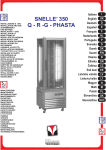


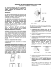

![[UK] Saver NG Data Sheets A1-2013](http://vs1.manualzilla.com/store/data/005759312_1-088a9b2c9a495b4ddfffe35115070dd1-150x150.png)